EP3199656A1 - Matériau d'outil froid et procédé de fabrication d'outil froid - Google Patents
Matériau d'outil froid et procédé de fabrication d'outil froid Download PDFInfo
- Publication number
- EP3199656A1 EP3199656A1 EP15832776.7A EP15832776A EP3199656A1 EP 3199656 A1 EP3199656 A1 EP 3199656A1 EP 15832776 A EP15832776 A EP 15832776A EP 3199656 A1 EP3199656 A1 EP 3199656A1
- Authority
- EP
- European Patent Office
- Prior art keywords
- carbides
- cold work
- work tool
- equivalent diameter
- hardness
- Prior art date
- Legal status (The legal status is an assumption and is not a legal conclusion. Google has not performed a legal analysis and makes no representation as to the accuracy of the status listed.)
- Granted
Links
- 239000000463 material Substances 0.000 title claims abstract description 102
- 238000004519 manufacturing process Methods 0.000 title claims abstract description 8
- 238000000034 method Methods 0.000 title description 16
- 150000001247 metal acetylides Chemical class 0.000 claims abstract description 122
- 238000005496 tempering Methods 0.000 claims abstract description 47
- 238000010791 quenching Methods 0.000 claims abstract description 30
- 230000000171 quenching effect Effects 0.000 claims abstract description 30
- 229910052799 carbon Inorganic materials 0.000 claims abstract description 26
- 239000000203 mixture Substances 0.000 claims abstract description 18
- 229910000734 martensite Inorganic materials 0.000 claims abstract description 14
- 229910052750 molybdenum Inorganic materials 0.000 claims abstract description 11
- 229910052721 tungsten Inorganic materials 0.000 claims abstract description 10
- 229910052804 chromium Inorganic materials 0.000 claims abstract description 9
- 229910052720 vanadium Inorganic materials 0.000 claims abstract description 7
- 229910000831 Steel Inorganic materials 0.000 description 29
- 239000010959 steel Substances 0.000 description 29
- 230000000694 effects Effects 0.000 description 24
- OKTJSMMVPCPJKN-UHFFFAOYSA-N Carbon Chemical compound [C] OKTJSMMVPCPJKN-UHFFFAOYSA-N 0.000 description 20
- 239000011159 matrix material Substances 0.000 description 17
- 239000011651 chromium Substances 0.000 description 14
- PXHVJJICTQNCMI-UHFFFAOYSA-N nickel Substances [Ni] PXHVJJICTQNCMI-UHFFFAOYSA-N 0.000 description 13
- 239000010955 niobium Substances 0.000 description 12
- 230000008569 process Effects 0.000 description 10
- 239000002994 raw material Substances 0.000 description 10
- 239000011572 manganese Substances 0.000 description 9
- 239000006104 solid solution Substances 0.000 description 9
- 238000010438 heat treatment Methods 0.000 description 8
- 238000003754 machining Methods 0.000 description 8
- 238000013507 mapping Methods 0.000 description 8
- 229910000822 Cold-work tool steel Inorganic materials 0.000 description 7
- 230000006866 deterioration Effects 0.000 description 7
- 238000009826 distribution Methods 0.000 description 7
- 230000000052 comparative effect Effects 0.000 description 6
- NINIDFKCEFEMDL-UHFFFAOYSA-N Sulfur Chemical compound [S] NINIDFKCEFEMDL-UHFFFAOYSA-N 0.000 description 5
- 229910045601 alloy Inorganic materials 0.000 description 5
- 239000000956 alloy Substances 0.000 description 5
- 238000000137 annealing Methods 0.000 description 5
- 238000005266 casting Methods 0.000 description 5
- 239000012535 impurity Substances 0.000 description 5
- 230000001965 increasing effect Effects 0.000 description 5
- 239000007858 starting material Substances 0.000 description 5
- 229910052717 sulfur Inorganic materials 0.000 description 5
- 239000011593 sulfur Substances 0.000 description 5
- XEEYBQQBJWHFJM-UHFFFAOYSA-N Iron Chemical compound [Fe] XEEYBQQBJWHFJM-UHFFFAOYSA-N 0.000 description 4
- 229910001566 austenite Inorganic materials 0.000 description 4
- BHEPBYXIRTUNPN-UHFFFAOYSA-N hydridophosphorus(.) (triplet) Chemical compound [PH] BHEPBYXIRTUNPN-UHFFFAOYSA-N 0.000 description 4
- 230000003287 optical effect Effects 0.000 description 4
- 239000000523 sample Substances 0.000 description 4
- 238000001816 cooling Methods 0.000 description 3
- 239000007787 solid Substances 0.000 description 3
- 238000007711 solidification Methods 0.000 description 3
- 230000008023 solidification Effects 0.000 description 3
- 229910000859 α-Fe Inorganic materials 0.000 description 3
- IJGRMHOSHXDMSA-UHFFFAOYSA-N Atomic nitrogen Chemical compound N#N IJGRMHOSHXDMSA-UHFFFAOYSA-N 0.000 description 2
- 238000012935 Averaging Methods 0.000 description 2
- VYZAMTAEIAYCRO-UHFFFAOYSA-N Chromium Chemical compound [Cr] VYZAMTAEIAYCRO-UHFFFAOYSA-N 0.000 description 2
- ZOKXTWBITQBERF-UHFFFAOYSA-N Molybdenum Chemical compound [Mo] ZOKXTWBITQBERF-UHFFFAOYSA-N 0.000 description 2
- VYPSYNLAJGMNEJ-UHFFFAOYSA-N Silicium dioxide Chemical compound O=[Si]=O VYPSYNLAJGMNEJ-UHFFFAOYSA-N 0.000 description 2
- 229910001315 Tool steel Inorganic materials 0.000 description 2
- 238000004458 analytical method Methods 0.000 description 2
- 230000015572 biosynthetic process Effects 0.000 description 2
- 229910001567 cementite Inorganic materials 0.000 description 2
- 230000008859 change Effects 0.000 description 2
- 239000008119 colloidal silica Substances 0.000 description 2
- 238000005520 cutting process Methods 0.000 description 2
- 230000007423 decrease Effects 0.000 description 2
- 230000003247 decreasing effect Effects 0.000 description 2
- 210000001787 dendrite Anatomy 0.000 description 2
- 229910003460 diamond Inorganic materials 0.000 description 2
- 239000010432 diamond Substances 0.000 description 2
- 229910052742 iron Inorganic materials 0.000 description 2
- 239000007788 liquid Substances 0.000 description 2
- 238000002844 melting Methods 0.000 description 2
- 230000008018 melting Effects 0.000 description 2
- 239000011733 molybdenum Substances 0.000 description 2
- 229910052760 oxygen Inorganic materials 0.000 description 2
- 230000000717 retained effect Effects 0.000 description 2
- 239000002002 slurry Substances 0.000 description 2
- 238000005728 strengthening Methods 0.000 description 2
- PWHULOQIROXLJO-UHFFFAOYSA-N Manganese Chemical compound [Mn] PWHULOQIROXLJO-UHFFFAOYSA-N 0.000 description 1
- 238000007550 Rockwell hardness test Methods 0.000 description 1
- 230000002730 additional effect Effects 0.000 description 1
- 229910052782 aluminium Inorganic materials 0.000 description 1
- QVGXLLKOCUKJST-UHFFFAOYSA-N atomic oxygen Chemical compound [O] QVGXLLKOCUKJST-UHFFFAOYSA-N 0.000 description 1
- 229910052791 calcium Inorganic materials 0.000 description 1
- 239000000470 constituent Substances 0.000 description 1
- 229910052802 copper Inorganic materials 0.000 description 1
- 239000006185 dispersion Substances 0.000 description 1
- 230000002708 enhancing effect Effects 0.000 description 1
- 238000005242 forging Methods 0.000 description 1
- 230000036541 health Effects 0.000 description 1
- KSOKAHYVTMZFBJ-UHFFFAOYSA-N iron;methane Chemical compound C.[Fe].[Fe].[Fe] KSOKAHYVTMZFBJ-UHFFFAOYSA-N 0.000 description 1
- 229910052749 magnesium Inorganic materials 0.000 description 1
- 229910052748 manganese Inorganic materials 0.000 description 1
- 238000005259 measurement Methods 0.000 description 1
- 238000010309 melting process Methods 0.000 description 1
- 229910052751 metal Inorganic materials 0.000 description 1
- 239000002184 metal Substances 0.000 description 1
- ZLANVVMKMCTKMT-UHFFFAOYSA-N methanidylidynevanadium(1+) Chemical class [V+]#[C-] ZLANVVMKMCTKMT-UHFFFAOYSA-N 0.000 description 1
- 229910052759 nickel Inorganic materials 0.000 description 1
- 229910052758 niobium Inorganic materials 0.000 description 1
- GUCVJGMIXFAOAE-UHFFFAOYSA-N niobium atom Chemical compound [Nb] GUCVJGMIXFAOAE-UHFFFAOYSA-N 0.000 description 1
- 229910052757 nitrogen Inorganic materials 0.000 description 1
- 239000001301 oxygen Substances 0.000 description 1
- 239000002245 particle Substances 0.000 description 1
- 229910001562 pearlite Inorganic materials 0.000 description 1
- 238000012545 processing Methods 0.000 description 1
- 230000004044 response Effects 0.000 description 1
- 238000005096 rolling process Methods 0.000 description 1
- 238000005204 segregation Methods 0.000 description 1
- 238000007493 shaping process Methods 0.000 description 1
- 229910052710 silicon Inorganic materials 0.000 description 1
- 239000010703 silicon Substances 0.000 description 1
- 239000000243 solution Substances 0.000 description 1
- WFKWXMTUELFFGS-UHFFFAOYSA-N tungsten Chemical compound [W] WFKWXMTUELFFGS-UHFFFAOYSA-N 0.000 description 1
- 239000010937 tungsten Substances 0.000 description 1
- -1 vanadium) forms carbides Chemical class 0.000 description 1
Images


Classifications
-
- C—CHEMISTRY; METALLURGY
- C21—METALLURGY OF IRON
- C21D—MODIFYING THE PHYSICAL STRUCTURE OF FERROUS METALS; GENERAL DEVICES FOR HEAT TREATMENT OF FERROUS OR NON-FERROUS METALS OR ALLOYS; MAKING METAL MALLEABLE, e.g. BY DECARBURISATION OR TEMPERING
- C21D1/00—General methods or devices for heat treatment, e.g. annealing, hardening, quenching or tempering
- C21D1/18—Hardening; Quenching with or without subsequent tempering
-
- C—CHEMISTRY; METALLURGY
- C21—METALLURGY OF IRON
- C21D—MODIFYING THE PHYSICAL STRUCTURE OF FERROUS METALS; GENERAL DEVICES FOR HEAT TREATMENT OF FERROUS OR NON-FERROUS METALS OR ALLOYS; MAKING METAL MALLEABLE, e.g. BY DECARBURISATION OR TEMPERING
- C21D8/00—Modifying the physical properties by deformation combined with, or followed by, heat treatment
- C21D8/02—Modifying the physical properties by deformation combined with, or followed by, heat treatment during manufacturing of plates or strips
- C21D8/0221—Modifying the physical properties by deformation combined with, or followed by, heat treatment during manufacturing of plates or strips characterised by the working steps
-
- C—CHEMISTRY; METALLURGY
- C21—METALLURGY OF IRON
- C21D—MODIFYING THE PHYSICAL STRUCTURE OF FERROUS METALS; GENERAL DEVICES FOR HEAT TREATMENT OF FERROUS OR NON-FERROUS METALS OR ALLOYS; MAKING METAL MALLEABLE, e.g. BY DECARBURISATION OR TEMPERING
- C21D9/00—Heat treatment, e.g. annealing, hardening, quenching or tempering, adapted for particular articles; Furnaces therefor
- C21D9/0068—Heat treatment, e.g. annealing, hardening, quenching or tempering, adapted for particular articles; Furnaces therefor for particular articles not mentioned below
-
- C—CHEMISTRY; METALLURGY
- C22—METALLURGY; FERROUS OR NON-FERROUS ALLOYS; TREATMENT OF ALLOYS OR NON-FERROUS METALS
- C22C—ALLOYS
- C22C37/00—Cast-iron alloys
- C22C37/06—Cast-iron alloys containing chromium
-
- C—CHEMISTRY; METALLURGY
- C22—METALLURGY; FERROUS OR NON-FERROUS ALLOYS; TREATMENT OF ALLOYS OR NON-FERROUS METALS
- C22C—ALLOYS
- C22C38/00—Ferrous alloys, e.g. steel alloys
- C22C38/001—Ferrous alloys, e.g. steel alloys containing N
-
- C—CHEMISTRY; METALLURGY
- C22—METALLURGY; FERROUS OR NON-FERROUS ALLOYS; TREATMENT OF ALLOYS OR NON-FERROUS METALS
- C22C—ALLOYS
- C22C38/00—Ferrous alloys, e.g. steel alloys
- C22C38/002—Ferrous alloys, e.g. steel alloys containing In, Mg, or other elements not provided for in one single group C22C38/001 - C22C38/60
-
- C—CHEMISTRY; METALLURGY
- C22—METALLURGY; FERROUS OR NON-FERROUS ALLOYS; TREATMENT OF ALLOYS OR NON-FERROUS METALS
- C22C—ALLOYS
- C22C38/00—Ferrous alloys, e.g. steel alloys
- C22C38/02—Ferrous alloys, e.g. steel alloys containing silicon
-
- C—CHEMISTRY; METALLURGY
- C22—METALLURGY; FERROUS OR NON-FERROUS ALLOYS; TREATMENT OF ALLOYS OR NON-FERROUS METALS
- C22C—ALLOYS
- C22C38/00—Ferrous alloys, e.g. steel alloys
- C22C38/04—Ferrous alloys, e.g. steel alloys containing manganese
-
- C—CHEMISTRY; METALLURGY
- C22—METALLURGY; FERROUS OR NON-FERROUS ALLOYS; TREATMENT OF ALLOYS OR NON-FERROUS METALS
- C22C—ALLOYS
- C22C38/00—Ferrous alloys, e.g. steel alloys
- C22C38/18—Ferrous alloys, e.g. steel alloys containing chromium
- C22C38/22—Ferrous alloys, e.g. steel alloys containing chromium with molybdenum or tungsten
-
- C—CHEMISTRY; METALLURGY
- C22—METALLURGY; FERROUS OR NON-FERROUS ALLOYS; TREATMENT OF ALLOYS OR NON-FERROUS METALS
- C22C—ALLOYS
- C22C38/00—Ferrous alloys, e.g. steel alloys
- C22C38/18—Ferrous alloys, e.g. steel alloys containing chromium
- C22C38/24—Ferrous alloys, e.g. steel alloys containing chromium with vanadium
-
- C—CHEMISTRY; METALLURGY
- C22—METALLURGY; FERROUS OR NON-FERROUS ALLOYS; TREATMENT OF ALLOYS OR NON-FERROUS METALS
- C22C—ALLOYS
- C22C38/00—Ferrous alloys, e.g. steel alloys
- C22C38/18—Ferrous alloys, e.g. steel alloys containing chromium
- C22C38/26—Ferrous alloys, e.g. steel alloys containing chromium with niobium or tantalum
-
- C—CHEMISTRY; METALLURGY
- C22—METALLURGY; FERROUS OR NON-FERROUS ALLOYS; TREATMENT OF ALLOYS OR NON-FERROUS METALS
- C22C—ALLOYS
- C22C38/00—Ferrous alloys, e.g. steel alloys
- C22C38/18—Ferrous alloys, e.g. steel alloys containing chromium
- C22C38/34—Ferrous alloys, e.g. steel alloys containing chromium with more than 1.5% by weight of silicon
-
- C—CHEMISTRY; METALLURGY
- C22—METALLURGY; FERROUS OR NON-FERROUS ALLOYS; TREATMENT OF ALLOYS OR NON-FERROUS METALS
- C22C—ALLOYS
- C22C38/00—Ferrous alloys, e.g. steel alloys
- C22C38/18—Ferrous alloys, e.g. steel alloys containing chromium
- C22C38/36—Ferrous alloys, e.g. steel alloys containing chromium with more than 1.7% by weight of carbon
-
- C—CHEMISTRY; METALLURGY
- C22—METALLURGY; FERROUS OR NON-FERROUS ALLOYS; TREATMENT OF ALLOYS OR NON-FERROUS METALS
- C22C—ALLOYS
- C22C38/00—Ferrous alloys, e.g. steel alloys
- C22C38/18—Ferrous alloys, e.g. steel alloys containing chromium
- C22C38/40—Ferrous alloys, e.g. steel alloys containing chromium with nickel
- C22C38/44—Ferrous alloys, e.g. steel alloys containing chromium with nickel with molybdenum or tungsten
-
- C—CHEMISTRY; METALLURGY
- C22—METALLURGY; FERROUS OR NON-FERROUS ALLOYS; TREATMENT OF ALLOYS OR NON-FERROUS METALS
- C22C—ALLOYS
- C22C38/00—Ferrous alloys, e.g. steel alloys
- C22C38/60—Ferrous alloys, e.g. steel alloys containing lead, selenium, tellurium, or antimony, or more than 0.04% by weight of sulfur
-
- C—CHEMISTRY; METALLURGY
- C21—METALLURGY OF IRON
- C21D—MODIFYING THE PHYSICAL STRUCTURE OF FERROUS METALS; GENERAL DEVICES FOR HEAT TREATMENT OF FERROUS OR NON-FERROUS METALS OR ALLOYS; MAKING METAL MALLEABLE, e.g. BY DECARBURISATION OR TEMPERING
- C21D2211/00—Microstructure comprising significant phases
- C21D2211/004—Dispersions; Precipitations
-
- C—CHEMISTRY; METALLURGY
- C21—METALLURGY OF IRON
- C21D—MODIFYING THE PHYSICAL STRUCTURE OF FERROUS METALS; GENERAL DEVICES FOR HEAT TREATMENT OF FERROUS OR NON-FERROUS METALS OR ALLOYS; MAKING METAL MALLEABLE, e.g. BY DECARBURISATION OR TEMPERING
- C21D2211/00—Microstructure comprising significant phases
- C21D2211/008—Martensite
Definitions
- the present invention relates to a cold work tool material suitable for various kinds of cold work tools such as press dies, forging dies, rolling dies or metal cutting tools.
- the present invention also relates to a method of manufacturing the cold work tool with use of the cold work tool material.
- a cold work tool material is manufactured from a raw material, as a starting material, such as a steel ingot or a bloom which is produced from the ingot.
- the starting material is subjected to various hot working and heat treatment to form a predetermined steel material, and then the steel material is subjected to an annealing process to produce the cold work tool material.
- the cold work tool material in the annealed condition having a low hardness is typically supplied to a manufacturer of a cold work tool.
- the material is machined into a shape of the tool, and thereafter quenched and tempered to adjust its hardness for use. After the adjustment of the hardness, finishing machining is typically conducted.
- quenching and tempering are conducted first for the material in the annealed condition, and then the machining is conducted for the shaping of the tool together with the finishing machining.
- quenching refers to an operation where a cold work tool material (or a cold work tool material that has been subjected to machining) is heated to an austenitic phase temperature range and then rapidly cooled to transform it into a martensitic structure.
- the cold work tool material has such a composition that can have a martensitic structure by the quenching.
- Non Patent Literature 1 " JIS-G-4404 (2006) Alloy Tool Steel Material", JIS Handbook (1) Iron and Steel I, Japanese Standards Association, January 23, 2013, pages 1652-1663
- the cold work tool materials of Patent Literatures 2 to 4 can have improved hardness after quenched and tempered.
- change of a tempering temperature brought about a low hardness in some cases.
- a high hardness was not obtained over a wide range of the tempering temperature.
- the tempering temperature is determined not only by the hardness of the cold work tool, but also from a viewpoint of a dimensional change during a heat treatment or adjustment of an amount of retained austenite.
- An objective of the present invention is to provide a cold work tool material for which a high hardness is obtained over a wide range of tempering temperature, and a method of manufacturing a cold work tool with use of the cold work tool material.
- the present invention provides a cold work tool material used after quenched and tempered.
- the material has an annealed structure including carbides and has a composition including, in mass%, C: 0.80% to 2.40%, Cr: 5.0% to 15.0%, Mo and W, alone or in combination in an amount of (Mo + 1/2W): 0.50% to 3.00%, and V: 0.10 to 1.50%, and the composition is adjusted such that the material has a martensitic structure by the quenching.
- a proportion of a number of carbides B having a circle equivalent diameter of more than 0.1 ⁇ m and not more than 0.4 ⁇ m to a number of carbides A having a circle equivalent diameter of more than 0.1 ⁇ m and not more than 2.0 ⁇ m is greater than 80.0%.
- a number density of the carbides A is not less than 9.0 ⁇ 10 5 per mm 2
- a number density of the carbides B is not less than 7.5 ⁇ 10 5 per mm 2 in the region of a length of 90 ⁇ m and a width of 90 ⁇ m,.
- the present invention also provides a method of manufacturing a cold work tool, including a step of quenching and tempering the cold work tool material of the present invention.
- a high hardness is obtained over a wide range of tempering temperature for the cold work tool material.
- the inventors investigated factors in an annealed structure of a cold work tool material, that influence on a hardness of a quenched and tempered material. As a result, they discovered that, among carbides existing in the annealed structure, a distribution of "solid solution carbides" that are to be solid-solved in a matrix at the time of the subsequent quenching process significantly influences the hardness after quenching and tempering. Then, the inventors found that a high hardness can be obtained over a wide range of a tempering temperature, not at a limited tempering temperature, by means of adjusting the distribution of the solid solution carbides, thereby achieved the present invention. Each component of the present invention is described below.
- hardness stability effect a high hardness can be obtained over a wide range of tempering temperature
- the raw material generates the martensitic structure from the annealed structure through quenching and tempering, and also when the annealed structure satisfies the requirement (3) described later, and preferably the requirement (4).
- it is effective to determine amounts of carbon and carbide-forming elements Cr, Mo, W or V among the elements for generating the martensitic structure, since the elements contribute to improving an "absolute value" of the hardness of the cold work tool.
- the composition includes, in mass%, C: 0.80% to 2.40%, Cr: 5.0% to 15.0%, Mo and W alone or in combination in an amount of (Mo + 1/2W): 0.50% to 3.00%, and V: 0.10 to 1.50%.
- the "hardness stability effect” acts synergistically therewith, thereby the cold work tool can obtain excellent mechanical properties of both "high hardness” and “stable degree of hardness”. Elements constituting the composition of the cold work tool material of the present invention are described below.
- C is a basic element of a cold work tool material. Carbon partially solid-solves in a matrix to provide a hardness thereto, and partially forms carbides to improve a wear resistance and a galling resistance. Also, solid solved carbon as an interstitial atom is expected to exhibit an I (interstitial atom) - S (substitutional atom) effect (carbon acts as drag resistance for solute atoms, and acts to enhance a strength of the cold work tool), if is added together with a substitutional atom having a high affinity with carbon, such as Cr. However, an excessive addition will cause deterioration of toughness due to an excessive increase in non-solid-solved carbides. Therefore, the carbon content is 0.80 to 2.40%. Preferably, the content is not less than 1.00%, more preferably not less than 1.30%. Furthermore, the content is preferably not more than 2.10%, more preferably not more than 1.80%, further more preferably not more than 1.60%.
- Cr chromium
- Cr is an element that increases hardenability. Further, Cr forms carbides to improve wear resistance. Cr also contributes to improve resistance to temper softening, and is a basic element of a cold work tool material. However, an excessive addition will cause formation of coarse non-solid-solved carbides and lead to a deterioration in toughness. Therefore, the Cr content is 5.0 to 15.0%.
- the content is preferably not more than 14.0%, more preferably not more than 13.0%.
- the content is preferably not less than 7.0%, more preferably not less than 9.0%, further more preferably not less than 10.0%.
- Mo and W cause fine carbides to precipitate or aggregate through tempering, thereby providing strength to a cold work tool.
- Mo and W can be added alone or in combination.
- An amount of addition can be specified by a Mo equivalent that is defined by a formula (Mo + 1/2W), since an atomic weight of W is approximately twice that of Mo. Of course, only either one of them may be added or both may be added. To achieve the above effects, the amount of addition is not less than 0.50% in terms of the value of (Mo + 1/2W). Preferably, the amount is not less than 0.60%. Since an excessive addition will cause deterioration of machinability and toughness, the amount is not more than 3.00% in terms of the value of (Mo + 1/2W). The amount is preferably not more than 2.00%, more preferably not more than 1.50%, further more preferably not more than 1.00%.
- V vanadium forms carbides and thus has effects of strengthening a matrix and improving wear resistance and resistance to temper softening. Furthermore, vanadium carbides distributed in an annealed structure function as "pinning particles" that suppress coarsening of austenite grains during heating for quenching, and thereby also contribute to improve toughness. To achieve the effects, an amount of addition of V is not less than 0.10%, preferably not less than 0.20%, more preferably not less than 0.40%. Furthermore, in order to act as solid solution carbides (described later) according to the present invention, not less than 0.60% of V may be added.
- the V content is not more than 1.50%, preferably not more than 1.00%, more preferably not more than 0.90%.
- the cold work tool material of the present invention may have the composition including the above elements.
- a composition may include the above elements and the balance of iron and inevitable impurities.
- the material may include following elements.
- Si is a deoxidizer in a melting process. An excessive addition of Si decreases hardenability. Furthermore, toughness of a cold work tool after quenched and tempered also decreases. Thus, the Si content is preferably not more than 2.00%, more preferably not more than 1.50%, further more preferably not more than 0.80%. On the other hand, Si solid-solves in a structure of the cold work tool, and has an effect of enhancing hardness of the tool. To obtain the effect, an amount of Si is preferable not less than 0.10%, more preferably not less than 0.30%.
- an amount of Mn is preferably not more than 1.50%, more preferably not more than 1.00%, further more preferably not more than 0.70%.
- Mn is an austenite-forming element, it has an effect of increasing hardenability.
- Mn has a large effect on improving machinability since it forms a non-metallic inclusion MnS.
- addition of Mn is preferably not less than 0.10%, more preferably not less than 0.20%.
- P phosphorous
- Phosphorous segregates in prior austenite grain boundaries during a heat treatment such as tempering, thereby making the grain boundaries brittle. Therefore, an amount of phosphorous is limited to not more than 0.050% to improve toughness of the cold work tool, including a case where phosphorous P is added. More preferably, the amount is not more than 0.030%.
- S sulfur
- Sulfur is normally included inevitably in various kinds of cold work tool materials, even though it is not added. Sulfur deteriorates hot workability of the material before hot working, and produces cracks during the hot working. Therefore, it is preferable to limit an amount of sulfur to not more than 0.050% to improve the hot workability of the material.
- the sulfur content is more preferably not more than 0.030%, further more preferably less than 0.0100%.
- sulfur has an effect of improving machinability by bonding with Mn to form a non-metallic inclusion MnS. An amount of more than 0.0300% may be added to achieve the effect.
- Ni nickel increases ductility of a matrix, thereby decreasing machinability.
- the Ni content is preferably not more than 1.00%, more preferably less than 0.50%, further more preferably less than 0.30%.
- the Ni content of less than 0.30% also corresponds to an upper limit of Ni in a case where Ni is included as an impurity.
- Ni suppresses generation of ferrite in the tool structure. Moreover, Ni is effective in providing excellent hardenability to the cold work tool material, and enables formation of a structure mainly composed of martensite, even when a cooling rate in quenching is mild, to prevent deterioration of toughness. Furthermore, since Ni also improves intrinsic toughness of the matrix, Ni may be added as needed according to the present invention. In the case of adding Ni, a preferable amount is not less than 0.10% while the upper limit is 1.00%. More preferably, the amount is not less than 0.30%, further more preferably not more than 0.80%.
- Nb (niobium) causes deterioration of machinability
- an amount of Nb is preferably not more than 1.50%, more preferably not more than 0.90%, further more preferably less than 0.30%.
- the amount of less than 0.30% of Nb corresponds to an upper limit of Nb in a case where Nb is included as an impurity.
- Nb forms carbides and has effects of strengthening a matrix and improving wear resistance. Moreover, Nb increases resistance to temper softening. Nb also has an effect of suppressing coarsening of grains, similarly to V, thereby contributing to improve toughness. Hence, Nb may be added as needed.
- an amount is preferably not less than 0.10% while the upper limit is 1.50%. The amount is more preferably not less than 0.30%, further more preferably not more than 1.00%.
- Cu, Al, Ca, Mg, O (oxygen) and N (nitrogen) are elements which may possibly remain in a steel as an inevitable impurity. It is preferable to limit an amount of the elements as low as possible in the cold work tool material of the present invention. On the other hand, small amounts of the elements may be added to effectively obtain additional effects such as morphology control of inclusions, or improvements of other mechanical properties and productivity. In the case, following ranges are permissible: Cu ⁇ 0.25%; Al ⁇ 0.25%; Ca ⁇ 0.0100%; Mg ⁇ 0.0100%; O ⁇ 0.0100%; and N ⁇ 0.0300%. These are preferable upper limits of the elements according to the present invention.
- the cold work tool material includes a cross sectional region of an annealed structure, the region having a length of 90 ⁇ m and a width of 90 ⁇ m and including no carbides having a circle equivalent diameter exceeding 5.0 ⁇ m, wherein, in the cross sectional region, a proportion of a number of carbides B having a circle equivalent diameter of more than 0.1 ⁇ m and not more than 0.4 ⁇ m to a number of carbides A having a circle equivalent diameter of more than 0.1 ⁇ m and not more than 2.0 ⁇ m is greater than 80.0%.
- the cold work tool material is typically produced from a raw material of a steel ingot or a bloom (bloomed from the ingot) as a starting material, through various hot working and heat treatment to form a predetermined steel material, and then through annealing process on the steel material, thereby finishing into a block shape.
- the ingot is typically produced by casting a molten steel that is adjusted to have a predetermined composition.
- the ingot has a structure including portions where large carbides aggregate and portions where smaller carbides aggregate (so-called "negative segregation" part), due to difference of starting timing of solidification (or due to difference of dendrite growth).
- the aggregates of carbides are extended along an extending direction of the hot working (that is, a longitudinal direction of the material), and are compressed in a vertical direction thereof (that is, a thickness direction of the material).
- the hot worked steel is annealed, and the annealed structure of the cold work tool material has a carbides distribution, that is a substantially laminate composed of layers of aggregates of large carbides and layers of aggregates of small carbides (see Fig. 1 ).
- carbides are seen as "light-colored dispersions" in a dark-colored matrix.
- the large carbides in the annealed structure function mainly as "non-solid solution carbides” that are not solid-solved in a matrix during heating for quenching, and remain in the structure after quenching and tempering and thereby contribute to improving the wear resistance of the cold work tool.
- the small carbides function as "solid solved carbides", that are liable to be solid-solved in the matrix during the heating for quenching.
- the carbides solid-solved in the matrix increase an amount of solid solved carbon in the matrix after quenching and tempering, and thereby increase hardness of the cold work tool.
- carbides having a circle equivalent diameter exceeding 5.0 ⁇ m in a cross-section of the annealed structure are deemed as non-solid solution carbides, and a region of "a length of 90 ⁇ m and a width of 90 ⁇ m" including only "solid solution carbides” having a circle equivalent diameter of not more than 5.0 ⁇ m is noted (for example, see a portion surrounded by a solid line in Fig. 1 ). That is, the region of "a length of 90 ⁇ m and a width of 90 ⁇ m" corresponds to a region of a "layer of aggregates of small carbides". It was discovered that the carbide distribution in this region can be utilized for the "hardness stability effect" of the present invention.
- the "hardness stability effect" can be achieved by a structure in which, a proportion of a number of carbides B having a circle equivalent diameter of more than 0.1 ⁇ m and not more than 0.4 ⁇ m to a number of carbides A having a circle equivalent diameter of more than 0.1 ⁇ m and not more than 2.0 ⁇ m, is more than 80.0% in the region of a length of 90 ⁇ m and a width of 90 ⁇ m.
- the lower limit of the circle equivalent diameter of both carbides A and B is defined to be 0.1 ⁇ m since the carbides having a circle equivalent diameter of not more than 0.1 ⁇ m can not be measured with accuracy.
- the proportion of the number of carbides B to the number of carbides A is preferably not less than 81.0%, and more preferably not less than 82.0%. Further preferably, the proportion is not less than 83.0%. While an upper limit of the proportion is not required particularly, the proportion will be realistically not more than 95.0%.
- a number density of the carbides A is not less than 9.0 ⁇ 10 5 per mm 2
- a number density of the carbides B is not less than 7.5 ⁇ 10 5 per mm 2 in the above region of a length of 90 ⁇ m and a width of 90 ⁇ m.
- the number density of the carbides A is more preferably not less than 9.5 ⁇ 10 5 per mm 2 , further more preferably not less than 10.0 ⁇ 10 5 per mm 2 . Particularly preferably, the number density is not less than 11.0 ⁇ 10 5 per mm 2 .
- the number density of the carbides B is more preferably not less than 8.0 ⁇ 10 5 per mm 2 , further more preferably not less than 8.5 ⁇ 10 5 per mm 2 . Particularly preferably, the number density is not less than 9.0 ⁇ 10 5 per mm 2 . Please note that the number density of the carbides B does not exceed the number density of the carbides A. Although upper limits of the number densities of the carbides A and carbides B are not particularly required, a relation such that the proportion is not more than 95.0% is realistic.
- a cross-sectional structure of the cold work tool material is observed with an optical microscope with a magnification of 200 times, for example.
- the observed cross section may be taken from a center portion of a cold work tool material for the cold work tool.
- the cross-section to be observed is parallel to an extending direction of the hot working (that is, a longitudinal direction of the material), specifically, a cross-section (so-called "TD cross-section") that is perpendicular to a TD direction (transverse direction) among the above parallel cross-section.
- This cross-section having an area of 15 mm ⁇ 15 mm for example can be polished to a mirror surface by means of a diamond slurry and colloidal silica.
- a region of a length of 90 ⁇ m and a width of 90 ⁇ m that does not include carbides having a circle equivalent diameter exceeding 5.0 ⁇ m is selected from the cross-sectional structure.
- large carbides having a circle equivalent diameter exceeding 5.0 can be easily observed from the field of view of the optical microscope (see Fig. 1 ).
- the circle equivalent diameter of the observed carbides can be determined by means of known image analysis software or the like.
- the selected region having a length of 90 ⁇ m and a width of 90 ⁇ m is observed with a scanning electron microscope (magnification of 3000 times), and the observed field is analyzed with an EPMA to obtain an elemental mapping image of C (carbon).
- a binarizing process is conducted with a threshold of not less than 25 counts (cps) of a detected intensity of carbon on an analysis result of the elemental mapping image of carbon, based on an amount of carbon forming carbides.
- cps counts
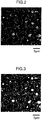
- Fig. 2 shows an elemental mapping image of carbon (field-of-view area: 30 ⁇ m ⁇ 30 ⁇ m) obtained by the above procedures for the region surrounded by a solid line in Fig. 1 .
- Fig. 3 is a view illustrating a carbide distribution in the region, which is obtained by the binarizing process for Fig. 2 .
- carbon and carbides are shown with a light-colored distribution.
- small carbides having a circle equivalent diameter of not more than 2.0 ⁇ m are distributed with a substantially uniform number density (see Fig. 3 ) in a region of the length of 90 ⁇ m and width of 90 ⁇ m in "a layer of aggregates of small carbides".
- a single elemental mapping image with an area of 30 ⁇ m ⁇ 30 ⁇ m (number of pixels: 530 ⁇ 530) is sufficient for confirming the "hardness stability effect" of the present invention, when the image is selected from the above described region having a length of 90 ⁇ m and a width of 90 ⁇ m.
- a position of the elemental mapping image may be arbitrarily selected from the above region.
- the series of measurement is conducted for at least two other regions having "a length of 90 ⁇ m and a width of 90 ⁇ m" separate from the above region having "a length of 90 ⁇ m and a width of 90 ⁇ m" (that is, a total of three regions) and averaging the numerical results, the "hardness stability effect" of the present invention can be sufficiently confirmed.
- the annealed structure of the cold work tool material of the present invention can be obtained by appropriately controlling a solidification process in a step of producing a steel ingot as the starting material. For example, it is important to adjust a "temperature of a molten steel" immediately prior to pouring it in a casting mold.
- a temperature of the molten steel is controlled at a lower temperature, for example, in a temperature range up to a temperature of a melting point of the cold work tool material + around 100°C.
- the molten steel cast in the mold is cooled so that it quickly passes a solid-liquid coexisting temperature zone, for example, by cooling within 60 minutes. Thereby, coarsening of crystallized carbides can be suppressed.
- a method of manufacturing a cold work tool comprising a step of quenching and tempering the above cold work tool material
- the above cold work tool material of the present invention is adjusted to have a martensitic structure having a predetermined hardness by quenching and tempering, and made into a cold work tool product.
- the cold work tool material is made into a shape of the cold work tool by various machining such as cutting, boring or the like. This machining is preferably conducted when the hardness of the material is low (that is, in an annealed state) before quenched and tempered. In this case, finishing machining may be further conducted after quenched and tempered.
- a material in a state of prehardened steel which has been subjected to performing quenching and tempering may be machined into a shape of a cold work tool together with the finishing machining.
- Temperatures of the quenching and the tempering differs depending on compositions of the material or target hardness or the like.
- the quenching temperature is approximately 950 to 1100°C
- the tempering temperature is approximately 150 to 600°C.
- the quenching temperature is approximately 1000 to 1050°C and the tempering temperature is approximately 180 to 540°C.
- a hardness of the quenched and tempered material is preferably not less than 58 HRC, and more preferably not less than 60 HRC. While an upper limit of the quenching and tempering hardness is not particularly defined, a hardness of not more than 66 HRC is realistic.
- a temperature of each molten steel for the raw materials 1 to 4 was adjusted to 1500°C before pouring in a casting mold. Dimensions of the casting molds for respective raw materials 1 to 4 were changed therebetween.
- cooling time period passing a solid-liquid coexisting temperature zone after the pouring was adjusted as follows, Material 1: 28 minutes, Material 2:45 minutes, Material 3: 106 minutes, and Material 4:168 minutes.
- the materials 1 to 4 correspond to a cold work tool steel SKD10 that is a standard steel grade of JIS-G-4404. [Table 1] mass% C Si Mn P S Cr Mo V Fe 1.48 0.53 0.42 0.022 0.0002 11.9 0.76 0.74 Bal. including impurities
- these raw materials were heated to 1160°C and hot worked. After the hot working, the raw materials were stood to cool. Thus, steel materials having a thickness of 25 mm, a width of 500 mm and a length of 100 mm were obtained. The materials were subjected to annealing at 860°C to obtain cold work tool materials 1 to 4 having a hardness of 190 HBW.
- a sample having a cross sectional area of 15 mm ⁇ 15 mm was cut out from a TD face at a center portion of each cold work tool material 1 to 4, which cross section was parallel to a extending direction of the hot working (that is, a longitudinal; direction of the material). Then, the section was polished to a mirror surface with use of a diamond slurry and colloidal silica. Next, three regions having a length of 90 ⁇ m and a width of 90 ⁇ m and including no carbides having a circle equivalent diameter exceeding 5.0 ⁇ m were selected from an annealed structure of each polished section.
- Fig. 1 shows an example of the region in the cold work tool material 1(see a portion surrounded by a solid line).
- a number of carbides A having a circle equivalent diameter more than 0.1 ⁇ m and not more than 2.0 ⁇ m, a number of carbides B having a circle equivalent diameter more than 0.1 ⁇ m and not more than 0.4 ⁇ m, and a proportion of the number of carbides B to the number of carbides A were determined in accordance with the above described means.
- An open source image processing software program "ImageJ" (http://imageJ.nih.gov/ij/) supplied from the National Institutes of Health (NIH) was used for image processing and analysis for determining the circle equivalent diameter and the number of the carbides.
- Fig. 2 illustrates an elemental mapping image of carbon in the region of the cold work tool material 1. A field-of-view area in Fig.
- Fig. 3 shows a binary image for the elemental mapping image in Fig. 2 with a threshold of a detected intensity of carbon of 25counts (cps).
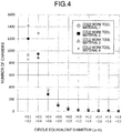
- Fig. 4 is a view plotting the numbers of carbides in the cold work tool materials 1 to 4 (in axis of ordinate) that were determined by the averaging of three regions in relation to ranges of the circle equivalent diameter of the carbides (in abscissa axis). "Carbides having a circle equivalent diameter exceeding 5.0 ⁇ m" were not included in the regions of the cold work tool materials 1 to 4.
- the cold work tool materials 1 to 4 were subjected to quenching from 1030°C, followed by tempering at a temperature of 100 to 540°C to obtain cold work tools 1 to 4 having a martensitic structure.
- a total of 10 conditions were adopted for the tempering temperatures, namely, low-temperature tempering conditions of 100°C, 150°C, 200°C and 300°C, and high-temperature tempering conditions of 450°C, 480°C, 490°C, 500°C, 520°C and 540°C.
- Rockwell hardness tests (C scale) were conducted at positions including the observed cross-sectional structures for each tempering temperature sample of each cold work tool 1 to 4.
- the hardness was measured at five points for each sample, and an average thereof was determined. The hardness as well as dependence of the hardness on the tempering temperature (stability of the hardness) was evaluated. The results are shown in Fig. 5 for low-temperature tempering conditions and Fig. 6 for high-temperature tempering conditions.
- the hardness of the cold work tools 1 and 2 according to the present invention was higher, over a wide temperature range, than the cold work tools 3 and 4 of the comparative examples in both cases of low-temperature tempering (100 to 300°C) and high-temperature tempering (450 to 540°C).
- the cold work tools 1 and 2 according to the invention could achieve high hardness of not less than 60 HRC that is required for a cold work tool in a wide range of tempering temperature of 450 to 510°C, while the cold work tools 3 and 4 of the comparative examples could obtain it only at tempering temperatures around 490°C.
- the cold work tools 1 and 2 could achieve the high hardness of not less than 60 HRC at two conditions of the tempering temperature 200°C and 500°C that are standard tempering temperatures for the cold work tool steel SKD10.
Landscapes
- Chemical & Material Sciences (AREA)
- Engineering & Computer Science (AREA)
- Materials Engineering (AREA)
- Mechanical Engineering (AREA)
- Metallurgy (AREA)
- Organic Chemistry (AREA)
- Physics & Mathematics (AREA)
- Thermal Sciences (AREA)
- Crystallography & Structural Chemistry (AREA)
- Heat Treatment Of Articles (AREA)
- Heat Treatment Of Steel (AREA)
Applications Claiming Priority (2)
| Application Number | Priority Date | Filing Date | Title |
|---|---|---|---|
| JP2014196035 | 2014-09-26 | ||
| PCT/JP2015/074902 WO2016047396A1 (fr) | 2014-09-26 | 2015-09-02 | Matériau d'outil froid et procédé de fabrication d'outil froid |
Publications (3)
| Publication Number | Publication Date |
|---|---|
| EP3199656A1 true EP3199656A1 (fr) | 2017-08-02 |
| EP3199656A4 EP3199656A4 (fr) | 2017-09-20 |
| EP3199656B1 EP3199656B1 (fr) | 2019-04-10 |
Family
ID=55580924
Family Applications (1)
| Application Number | Title | Priority Date | Filing Date |
|---|---|---|---|
| EP15832776.7A Active EP3199656B1 (fr) | 2014-09-26 | 2015-09-02 | Matériau pour outil à froid et procédé de fabrication d'outil froid |
Country Status (8)
| Country | Link |
|---|---|
| US (1) | US9890435B2 (fr) |
| EP (1) | EP3199656B1 (fr) |
| JP (2) | JP6057141B2 (fr) |
| KR (1) | KR101828228B1 (fr) |
| CN (1) | CN105637108B (fr) |
| TR (1) | TR201909240T4 (fr) |
| TW (1) | TWI592502B (fr) |
| WO (1) | WO2016047396A1 (fr) |
Cited By (1)
| Publication number | Priority date | Publication date | Assignee | Title |
|---|---|---|---|---|
| EP3241629A4 (fr) * | 2015-03-26 | 2017-11-15 | Hitachi Metals, Ltd. | Outil d'écrouissage, et procédé de fabrication de cet outil |
Families Citing this family (3)
| Publication number | Priority date | Publication date | Assignee | Title |
|---|---|---|---|---|
| WO2017158988A1 (fr) * | 2016-03-18 | 2017-09-21 | 日立金属株式会社 | Matériau d'outil de formage à froid et procédé de fabrication d'outil de formage à froid |
| KR20210062726A (ko) | 2017-03-01 | 2021-05-31 | 에이케이 스틸 프로퍼티즈 인코포레이티드 | 극도로 높은 강도를 갖는 프레스 경화 강 |
| CN113604744B (zh) * | 2021-08-10 | 2022-12-27 | 攀钢集团攀枝花钢铁研究院有限公司 | 一种高强韧冷作模具钢及其制备方法 |
Family Cites Families (17)
| Publication number | Priority date | Publication date | Assignee | Title |
|---|---|---|---|---|
| JPS6349352A (ja) | 1986-08-13 | 1988-03-02 | Hitachi Metals Ltd | 工具鋼連鋳鋳片の内質改善方法 |
| JP2684736B2 (ja) * | 1988-12-27 | 1997-12-03 | 大同特殊鋼株式会社 | 粉末冷間工具鋼 |
| JPH05156407A (ja) | 1991-12-06 | 1993-06-22 | Hitachi Metals Ltd | 高性能転造ダイス用鋼およびその製造方法 |
| JP3497387B2 (ja) | 1998-08-31 | 2004-02-16 | 山陽特殊製鋼株式会社 | 高硬度冷間工具鋼よりなる金型及び工具 |
| JP2001123247A (ja) | 1999-10-21 | 2001-05-08 | Daido Steel Co Ltd | 被削性に優れた冷間工具鋼 |
| JP4179024B2 (ja) * | 2003-04-09 | 2008-11-12 | 日立金属株式会社 | 高速度工具鋼及びその製造方法 |
| JP4403875B2 (ja) | 2004-05-14 | 2010-01-27 | 大同特殊鋼株式会社 | 冷間工具鋼 |
| JP2006193790A (ja) * | 2005-01-14 | 2006-07-27 | Daido Steel Co Ltd | 冷間工具鋼 |
| JP2007046139A (ja) | 2005-08-12 | 2007-02-22 | Daido Steel Co Ltd | 鋼材の製造方法 |
| JP4322239B2 (ja) | 2005-09-13 | 2009-08-26 | 日本高周波鋼業株式会社 | 冷間工具鋼及びその製造方法 |
| KR101138043B1 (ko) * | 2007-10-31 | 2012-04-23 | 다이도 토쿠슈코 카부시키가이샤 | 공구용 강과 그 제조방법 |
| JP5359582B2 (ja) | 2009-06-12 | 2013-12-04 | 日立金属株式会社 | 焼入れ用工具鋼素材 |
| CN103119187B (zh) * | 2010-09-27 | 2015-09-16 | 日立金属株式会社 | 表面pvd处理用高硬度预硬冷作工具钢及其制造方法、以及其表面pvd处理方法 |
| EP2679697B1 (fr) * | 2011-02-21 | 2018-06-27 | Hitachi Metals, Ltd. | Procédé de fabrication de matrice pour formage à froid |
| US8920296B2 (en) | 2011-03-04 | 2014-12-30 | Åkers AB | Forged roll meeting the requirements of the cold rolling industry and a method for production of such a roll |
| JP5522854B2 (ja) | 2011-06-01 | 2014-06-18 | 株式会社日本製鋼所 | 冷間工具鋼およびその製造方法 |
| JP2014145100A (ja) | 2013-01-28 | 2014-08-14 | Sanyo Special Steel Co Ltd | 合金添加量を低減した冷間工具鋼 |
-
2015
- 2015-09-02 KR KR1020177007878A patent/KR101828228B1/ko active IP Right Grant
- 2015-09-02 US US14/914,380 patent/US9890435B2/en active Active
- 2015-09-02 WO PCT/JP2015/074902 patent/WO2016047396A1/fr active Application Filing
- 2015-09-02 TR TR2019/09240T patent/TR201909240T4/tr unknown
- 2015-09-02 EP EP15832776.7A patent/EP3199656B1/fr active Active
- 2015-09-02 CN CN201580001701.XA patent/CN105637108B/zh active Active
- 2015-09-02 JP JP2016500419A patent/JP6057141B2/ja active Active
- 2015-09-22 TW TW104131199A patent/TWI592502B/zh active
-
2016
- 2016-09-21 JP JP2016184417A patent/JP2017025413A/ja active Pending
Cited By (2)
| Publication number | Priority date | Publication date | Assignee | Title |
|---|---|---|---|---|
| EP3241629A4 (fr) * | 2015-03-26 | 2017-11-15 | Hitachi Metals, Ltd. | Outil d'écrouissage, et procédé de fabrication de cet outil |
| US10844456B2 (en) | 2015-03-26 | 2020-11-24 | Hitachi Metals, Ltd. | Cold work tool and method for manufacturing same |
Also Published As
| Publication number | Publication date |
|---|---|
| US20170204486A1 (en) | 2017-07-20 |
| KR101828228B1 (ko) | 2018-02-09 |
| EP3199656B1 (fr) | 2019-04-10 |
| KR20170036125A (ko) | 2017-03-31 |
| JPWO2016047396A1 (ja) | 2017-04-27 |
| US9890435B2 (en) | 2018-02-13 |
| EP3199656A4 (fr) | 2017-09-20 |
| TR201909240T4 (tr) | 2019-07-22 |
| TW201615862A (zh) | 2016-05-01 |
| CN105637108B (zh) | 2017-08-11 |
| JP2017025413A (ja) | 2017-02-02 |
| CN105637108A (zh) | 2016-06-01 |
| JP6057141B2 (ja) | 2017-01-11 |
| TWI592502B (zh) | 2017-07-21 |
| WO2016047396A1 (fr) | 2016-03-31 |
Similar Documents
| Publication | Publication Date | Title |
|---|---|---|
| US20120018063A1 (en) | Case-hardened steel superiorin cold workability, machinability, and fatigue characteristics after carburized quenching and method of production of same | |
| EP3150735B1 (fr) | Matériau d'outil de formage à chaud et procédé pour la fabrication d'un outil de formage à chaud | |
| KR20130125816A (ko) | 기소강 및 그의 제조 방법, 및 기소강을 이용한 기계 구조 부품 | |
| EP3199656B1 (fr) | Matériau pour outil à froid et procédé de fabrication d'outil froid | |
| KR20190028782A (ko) | 고주파 담금질용 강 | |
| EP3305934B1 (fr) | Matériau d'outil de formage à froid et procédé de fabrication d'outil de formage à froid | |
| EP2682491A1 (fr) | Acier pour outil de travail à chaud doté d'une excellente ténacité et son procédé de production | |
| JP2012214833A (ja) | 冷間工具鋼 | |
| EP3263730B1 (fr) | Outil de travail à chaud et son procédé de fabrication | |
| EP3173500B2 (fr) | Matériau d'outil de travail à chaud, procédé de fabrication d'outil de travail à chaud et outil de travail à chaud | |
| JP6650104B2 (ja) | 冷間工具材料および冷間工具の製造方法 | |
| EP3255165B1 (fr) | Matériau pour outil de travail à froid, outil de travail à froid et procédé pour le fabriquer | |
| JP7061263B2 (ja) | 冷間工具材料および冷間工具の製造方法 | |
| US10844456B2 (en) | Cold work tool and method for manufacturing same | |
| KR101605964B1 (ko) | 금형강 및 이의 제조방법 | |
| JP2013185205A (ja) | 肌焼用鋼部品 |
Legal Events
| Date | Code | Title | Description |
|---|---|---|---|
| STAA | Information on the status of an ep patent application or granted ep patent |
Free format text: STATUS: THE INTERNATIONAL PUBLICATION HAS BEEN MADE |
|
| PUAI | Public reference made under article 153(3) epc to a published international application that has entered the european phase |
Free format text: ORIGINAL CODE: 0009012 |
|
| STAA | Information on the status of an ep patent application or granted ep patent |
Free format text: STATUS: REQUEST FOR EXAMINATION WAS MADE |
|
| 17P | Request for examination filed |
Effective date: 20160223 |
|
| AK | Designated contracting states |
Kind code of ref document: A1 Designated state(s): AL AT BE BG CH CY CZ DE DK EE ES FI FR GB GR HR HU IE IS IT LI LT LU LV MC MK MT NL NO PL PT RO RS SE SI SK SM TR |
|
| AX | Request for extension of the european patent |
Extension state: BA ME |
|
| A4 | Supplementary search report drawn up and despatched |
Effective date: 20170821 |
|
| RIC1 | Information provided on ipc code assigned before grant |
Ipc: C22C 38/02 20060101ALI20170814BHEP Ipc: C22C 38/04 20060101ALI20170814BHEP Ipc: C22C 38/60 20060101ALI20170814BHEP Ipc: C22C 38/34 20060101ALI20170814BHEP Ipc: C21D 9/00 20060101ALI20170814BHEP Ipc: C22C 38/24 20060101ALI20170814BHEP Ipc: C21D 8/02 20060101ALI20170814BHEP Ipc: C22C 37/06 20060101ALI20170814BHEP Ipc: C22C 38/44 20060101ALI20170814BHEP Ipc: C22C 38/26 20060101ALI20170814BHEP Ipc: C22C 38/36 20060101ALI20170814BHEP Ipc: C21D 1/18 20060101ALI20170814BHEP Ipc: C22C 38/22 20060101ALI20170814BHEP Ipc: C22C 38/00 20060101AFI20170814BHEP |
|
| DAV | Request for validation of the european patent (deleted) | ||
| DAX | Request for extension of the european patent (deleted) | ||
| GRAP | Despatch of communication of intention to grant a patent |
Free format text: ORIGINAL CODE: EPIDOSNIGR1 |
|
| STAA | Information on the status of an ep patent application or granted ep patent |
Free format text: STATUS: GRANT OF PATENT IS INTENDED |
|
| INTG | Intention to grant announced |
Effective date: 20181015 |
|
| GRAS | Grant fee paid |
Free format text: ORIGINAL CODE: EPIDOSNIGR3 |
|
| GRAA | (expected) grant |
Free format text: ORIGINAL CODE: 0009210 |
|
| STAA | Information on the status of an ep patent application or granted ep patent |
Free format text: STATUS: THE PATENT HAS BEEN GRANTED |
|
| AK | Designated contracting states |
Kind code of ref document: B1 Designated state(s): AL AT BE BG CH CY CZ DE DK EE ES FI FR GB GR HR HU IE IS IT LI LT LU LV MC MK MT NL NO PL PT RO RS SE SI SK SM TR |
|
| REG | Reference to a national code |
Ref country code: GB Ref legal event code: FG4D |
|
| REG | Reference to a national code |
Ref country code: CH Ref legal event code: EP Ref country code: AT Ref legal event code: REF Ref document number: 1118729 Country of ref document: AT Kind code of ref document: T Effective date: 20190415 |
|
| REG | Reference to a national code |
Ref country code: IE Ref legal event code: FG4D |
|
| REG | Reference to a national code |
Ref country code: DE Ref legal event code: R096 Ref document number: 602015028239 Country of ref document: DE |
|
| REG | Reference to a national code |
Ref country code: NL Ref legal event code: MP Effective date: 20190410 |
|
| REG | Reference to a national code |
Ref country code: LT Ref legal event code: MG4D |
|
| REG | Reference to a national code |
Ref country code: AT Ref legal event code: MK05 Ref document number: 1118729 Country of ref document: AT Kind code of ref document: T Effective date: 20190410 |
|
| PG25 | Lapsed in a contracting state [announced via postgrant information from national office to epo] |
Ref country code: NL Free format text: LAPSE BECAUSE OF FAILURE TO SUBMIT A TRANSLATION OF THE DESCRIPTION OR TO PAY THE FEE WITHIN THE PRESCRIBED TIME-LIMIT Effective date: 20190410 |
|
| PG25 | Lapsed in a contracting state [announced via postgrant information from national office to epo] |
Ref country code: PT Free format text: LAPSE BECAUSE OF FAILURE TO SUBMIT A TRANSLATION OF THE DESCRIPTION OR TO PAY THE FEE WITHIN THE PRESCRIBED TIME-LIMIT Effective date: 20190910 Ref country code: HR Free format text: LAPSE BECAUSE OF FAILURE TO SUBMIT A TRANSLATION OF THE DESCRIPTION OR TO PAY THE FEE WITHIN THE PRESCRIBED TIME-LIMIT Effective date: 20190410 Ref country code: ES Free format text: LAPSE BECAUSE OF FAILURE TO SUBMIT A TRANSLATION OF THE DESCRIPTION OR TO PAY THE FEE WITHIN THE PRESCRIBED TIME-LIMIT Effective date: 20190410 Ref country code: LT Free format text: LAPSE BECAUSE OF FAILURE TO SUBMIT A TRANSLATION OF THE DESCRIPTION OR TO PAY THE FEE WITHIN THE PRESCRIBED TIME-LIMIT Effective date: 20190410 Ref country code: FI Free format text: LAPSE BECAUSE OF FAILURE TO SUBMIT A TRANSLATION OF THE DESCRIPTION OR TO PAY THE FEE WITHIN THE PRESCRIBED TIME-LIMIT Effective date: 20190410 Ref country code: AL Free format text: LAPSE BECAUSE OF FAILURE TO SUBMIT A TRANSLATION OF THE DESCRIPTION OR TO PAY THE FEE WITHIN THE PRESCRIBED TIME-LIMIT Effective date: 20190410 Ref country code: NO Free format text: LAPSE BECAUSE OF FAILURE TO SUBMIT A TRANSLATION OF THE DESCRIPTION OR TO PAY THE FEE WITHIN THE PRESCRIBED TIME-LIMIT Effective date: 20190710 Ref country code: SE Free format text: LAPSE BECAUSE OF FAILURE TO SUBMIT A TRANSLATION OF THE DESCRIPTION OR TO PAY THE FEE WITHIN THE PRESCRIBED TIME-LIMIT Effective date: 20190410 |
|
| PG25 | Lapsed in a contracting state [announced via postgrant information from national office to epo] |
Ref country code: BG Free format text: LAPSE BECAUSE OF FAILURE TO SUBMIT A TRANSLATION OF THE DESCRIPTION OR TO PAY THE FEE WITHIN THE PRESCRIBED TIME-LIMIT Effective date: 20190710 Ref country code: PL Free format text: LAPSE BECAUSE OF FAILURE TO SUBMIT A TRANSLATION OF THE DESCRIPTION OR TO PAY THE FEE WITHIN THE PRESCRIBED TIME-LIMIT Effective date: 20190410 Ref country code: GR Free format text: LAPSE BECAUSE OF FAILURE TO SUBMIT A TRANSLATION OF THE DESCRIPTION OR TO PAY THE FEE WITHIN THE PRESCRIBED TIME-LIMIT Effective date: 20190711 Ref country code: LV Free format text: LAPSE BECAUSE OF FAILURE TO SUBMIT A TRANSLATION OF THE DESCRIPTION OR TO PAY THE FEE WITHIN THE PRESCRIBED TIME-LIMIT Effective date: 20190410 Ref country code: RS Free format text: LAPSE BECAUSE OF FAILURE TO SUBMIT A TRANSLATION OF THE DESCRIPTION OR TO PAY THE FEE WITHIN THE PRESCRIBED TIME-LIMIT Effective date: 20190410 |
|
| PG25 | Lapsed in a contracting state [announced via postgrant information from national office to epo] |
Ref country code: AT Free format text: LAPSE BECAUSE OF FAILURE TO SUBMIT A TRANSLATION OF THE DESCRIPTION OR TO PAY THE FEE WITHIN THE PRESCRIBED TIME-LIMIT Effective date: 20190410 Ref country code: IS Free format text: LAPSE BECAUSE OF FAILURE TO SUBMIT A TRANSLATION OF THE DESCRIPTION OR TO PAY THE FEE WITHIN THE PRESCRIBED TIME-LIMIT Effective date: 20190810 |
|
| REG | Reference to a national code |
Ref country code: DE Ref legal event code: R097 Ref document number: 602015028239 Country of ref document: DE |
|
| PG25 | Lapsed in a contracting state [announced via postgrant information from national office to epo] |
Ref country code: EE Free format text: LAPSE BECAUSE OF FAILURE TO SUBMIT A TRANSLATION OF THE DESCRIPTION OR TO PAY THE FEE WITHIN THE PRESCRIBED TIME-LIMIT Effective date: 20190410 Ref country code: SK Free format text: LAPSE BECAUSE OF FAILURE TO SUBMIT A TRANSLATION OF THE DESCRIPTION OR TO PAY THE FEE WITHIN THE PRESCRIBED TIME-LIMIT Effective date: 20190410 Ref country code: CZ Free format text: LAPSE BECAUSE OF FAILURE TO SUBMIT A TRANSLATION OF THE DESCRIPTION OR TO PAY THE FEE WITHIN THE PRESCRIBED TIME-LIMIT Effective date: 20190410 Ref country code: RO Free format text: LAPSE BECAUSE OF FAILURE TO SUBMIT A TRANSLATION OF THE DESCRIPTION OR TO PAY THE FEE WITHIN THE PRESCRIBED TIME-LIMIT Effective date: 20190410 Ref country code: DK Free format text: LAPSE BECAUSE OF FAILURE TO SUBMIT A TRANSLATION OF THE DESCRIPTION OR TO PAY THE FEE WITHIN THE PRESCRIBED TIME-LIMIT Effective date: 20190410 |
|
| PLBE | No opposition filed within time limit |
Free format text: ORIGINAL CODE: 0009261 |
|
| STAA | Information on the status of an ep patent application or granted ep patent |
Free format text: STATUS: NO OPPOSITION FILED WITHIN TIME LIMIT |
|
| PG25 | Lapsed in a contracting state [announced via postgrant information from national office to epo] |
Ref country code: SM Free format text: LAPSE BECAUSE OF FAILURE TO SUBMIT A TRANSLATION OF THE DESCRIPTION OR TO PAY THE FEE WITHIN THE PRESCRIBED TIME-LIMIT Effective date: 20190410 |
|
| 26N | No opposition filed |
Effective date: 20200113 |
|
| PG25 | Lapsed in a contracting state [announced via postgrant information from national office to epo] |
Ref country code: MC Free format text: LAPSE BECAUSE OF FAILURE TO SUBMIT A TRANSLATION OF THE DESCRIPTION OR TO PAY THE FEE WITHIN THE PRESCRIBED TIME-LIMIT Effective date: 20190410 Ref country code: SI Free format text: LAPSE BECAUSE OF FAILURE TO SUBMIT A TRANSLATION OF THE DESCRIPTION OR TO PAY THE FEE WITHIN THE PRESCRIBED TIME-LIMIT Effective date: 20190410 |
|
| REG | Reference to a national code |
Ref country code: CH Ref legal event code: PL |
|
| PG25 | Lapsed in a contracting state [announced via postgrant information from national office to epo] |
Ref country code: LI Free format text: LAPSE BECAUSE OF NON-PAYMENT OF DUE FEES Effective date: 20190930 Ref country code: CH Free format text: LAPSE BECAUSE OF NON-PAYMENT OF DUE FEES Effective date: 20190930 Ref country code: IE Free format text: LAPSE BECAUSE OF NON-PAYMENT OF DUE FEES Effective date: 20190902 Ref country code: LU Free format text: LAPSE BECAUSE OF NON-PAYMENT OF DUE FEES Effective date: 20190902 |
|
| REG | Reference to a national code |
Ref country code: BE Ref legal event code: MM Effective date: 20190930 |
|
| PG25 | Lapsed in a contracting state [announced via postgrant information from national office to epo] |
Ref country code: BE Free format text: LAPSE BECAUSE OF NON-PAYMENT OF DUE FEES Effective date: 20190930 |
|
| PG25 | Lapsed in a contracting state [announced via postgrant information from national office to epo] |
Ref country code: FR Free format text: LAPSE BECAUSE OF NON-PAYMENT OF DUE FEES Effective date: 20190930 |
|
| PG25 | Lapsed in a contracting state [announced via postgrant information from national office to epo] |
Ref country code: CY Free format text: LAPSE BECAUSE OF FAILURE TO SUBMIT A TRANSLATION OF THE DESCRIPTION OR TO PAY THE FEE WITHIN THE PRESCRIBED TIME-LIMIT Effective date: 20190410 |
|
| PG25 | Lapsed in a contracting state [announced via postgrant information from national office to epo] |
Ref country code: HU Free format text: LAPSE BECAUSE OF FAILURE TO SUBMIT A TRANSLATION OF THE DESCRIPTION OR TO PAY THE FEE WITHIN THE PRESCRIBED TIME-LIMIT; INVALID AB INITIO Effective date: 20150902 Ref country code: MT Free format text: LAPSE BECAUSE OF FAILURE TO SUBMIT A TRANSLATION OF THE DESCRIPTION OR TO PAY THE FEE WITHIN THE PRESCRIBED TIME-LIMIT Effective date: 20190410 |
|
| PG25 | Lapsed in a contracting state [announced via postgrant information from national office to epo] |
Ref country code: MK Free format text: LAPSE BECAUSE OF FAILURE TO SUBMIT A TRANSLATION OF THE DESCRIPTION OR TO PAY THE FEE WITHIN THE PRESCRIBED TIME-LIMIT Effective date: 20190410 |
|
| P01 | Opt-out of the competence of the unified patent court (upc) registered |
Effective date: 20230525 |
|
| PGFP | Annual fee paid to national office [announced via postgrant information from national office to epo] |
Ref country code: TR Payment date: 20230901 Year of fee payment: 9 Ref country code: IT Payment date: 20230810 Year of fee payment: 9 Ref country code: GB Payment date: 20230727 Year of fee payment: 9 |
|
| PGFP | Annual fee paid to national office [announced via postgrant information from national office to epo] |
Ref country code: DE Payment date: 20230802 Year of fee payment: 9 |