EP3199452A2 - Propellerblätter mit eisabstossender beschichtung - Google Patents
Propellerblätter mit eisabstossender beschichtung Download PDFInfo
- Publication number
- EP3199452A2 EP3199452A2 EP17153387.0A EP17153387A EP3199452A2 EP 3199452 A2 EP3199452 A2 EP 3199452A2 EP 17153387 A EP17153387 A EP 17153387A EP 3199452 A2 EP3199452 A2 EP 3199452A2
- Authority
- EP
- European Patent Office
- Prior art keywords
- propeller blade
- coating
- blade
- color
- inner region
- Prior art date
- Legal status (The legal status is an assumption and is not a legal conclusion. Google has not performed a legal analysis and makes no representation as to the accuracy of the status listed.)
- Withdrawn
Links
- 239000011248 coating agent Substances 0.000 title claims abstract description 136
- 238000000576 coating method Methods 0.000 title claims abstract description 136
- 239000000463 material Substances 0.000 claims abstract description 59
- 239000000758 substrate Substances 0.000 claims description 84
- 238000011179 visual inspection Methods 0.000 claims description 28
- 238000000034 method Methods 0.000 claims description 26
- 239000003086 colorant Substances 0.000 claims description 23
- 238000007689 inspection Methods 0.000 claims description 14
- 238000012423 maintenance Methods 0.000 claims description 13
- 230000000007 visual effect Effects 0.000 claims description 12
- 230000000977 initiatory effect Effects 0.000 claims description 6
- 230000004044 response Effects 0.000 claims description 3
- 239000010410 layer Substances 0.000 description 31
- 238000009825 accumulation Methods 0.000 description 8
- 230000008901 benefit Effects 0.000 description 4
- 229920000642 polymer Polymers 0.000 description 4
- 229920001084 poly(chloroprene) Polymers 0.000 description 3
- 230000009471 action Effects 0.000 description 2
- 239000012790 adhesive layer Substances 0.000 description 2
- 230000001133 acceleration Effects 0.000 description 1
- 239000000853 adhesive Substances 0.000 description 1
- 230000001070 adhesive effect Effects 0.000 description 1
- 230000015572 biosynthetic process Effects 0.000 description 1
- 125000004122 cyclic group Chemical group 0.000 description 1
- 238000010586 diagram Methods 0.000 description 1
- 229920001971 elastomer Polymers 0.000 description 1
- 230000006870 function Effects 0.000 description 1
- 230000005484 gravity Effects 0.000 description 1
- 238000010438 heat treatment Methods 0.000 description 1
- 238000002955 isolation Methods 0.000 description 1
- 230000003287 optical effect Effects 0.000 description 1
- 230000009467 reduction Effects 0.000 description 1
Images


Classifications
-
- B—PERFORMING OPERATIONS; TRANSPORTING
- B64—AIRCRAFT; AVIATION; COSMONAUTICS
- B64C—AEROPLANES; HELICOPTERS
- B64C11/00—Propellers, e.g. of ducted type; Features common to propellers and rotors for rotorcraft
- B64C11/16—Blades
- B64C11/20—Constructional features
- B64C11/205—Constructional features for protecting blades, e.g. coating
-
- B—PERFORMING OPERATIONS; TRANSPORTING
- B64—AIRCRAFT; AVIATION; COSMONAUTICS
- B64C—AEROPLANES; HELICOPTERS
- B64C11/00—Propellers, e.g. of ducted type; Features common to propellers and rotors for rotorcraft
- B64C11/16—Blades
- B64C11/20—Constructional features
-
- B—PERFORMING OPERATIONS; TRANSPORTING
- B64—AIRCRAFT; AVIATION; COSMONAUTICS
- B64D—EQUIPMENT FOR FITTING IN OR TO AIRCRAFT; FLIGHT SUITS; PARACHUTES; ARRANGEMENT OR MOUNTING OF POWER PLANTS OR PROPULSION TRANSMISSIONS IN AIRCRAFT
- B64D15/00—De-icing or preventing icing on exterior surfaces of aircraft
-
- B—PERFORMING OPERATIONS; TRANSPORTING
- B64—AIRCRAFT; AVIATION; COSMONAUTICS
- B64F—GROUND OR AIRCRAFT-CARRIER-DECK INSTALLATIONS SPECIALLY ADAPTED FOR USE IN CONNECTION WITH AIRCRAFT; DESIGNING, MANUFACTURING, ASSEMBLING, CLEANING, MAINTAINING OR REPAIRING AIRCRAFT, NOT OTHERWISE PROVIDED FOR; HANDLING, TRANSPORTING, TESTING OR INSPECTING AIRCRAFT COMPONENTS, NOT OTHERWISE PROVIDED FOR
- B64F5/00—Designing, manufacturing, assembling, cleaning, maintaining or repairing aircraft, not otherwise provided for; Handling, transporting, testing or inspecting aircraft components, not otherwise provided for
- B64F5/40—Maintaining or repairing aircraft
-
- B—PERFORMING OPERATIONS; TRANSPORTING
- B64—AIRCRAFT; AVIATION; COSMONAUTICS
- B64F—GROUND OR AIRCRAFT-CARRIER-DECK INSTALLATIONS SPECIALLY ADAPTED FOR USE IN CONNECTION WITH AIRCRAFT; DESIGNING, MANUFACTURING, ASSEMBLING, CLEANING, MAINTAINING OR REPAIRING AIRCRAFT, NOT OTHERWISE PROVIDED FOR; HANDLING, TRANSPORTING, TESTING OR INSPECTING AIRCRAFT COMPONENTS, NOT OTHERWISE PROVIDED FOR
- B64F5/00—Designing, manufacturing, assembling, cleaning, maintaining or repairing aircraft, not otherwise provided for; Handling, transporting, testing or inspecting aircraft components, not otherwise provided for
- B64F5/60—Testing or inspecting aircraft components or systems
Definitions
- Contemporary turbo-prop engine aircraft can include one or more propellers attached to wings of the aircraft.
- Propellers fitted to aircraft that are approved for flight into known icing conditions must include provisions to prevent unacceptable levels of ice accumulation on the propeller blades. Ice build-up on the propeller blade affects the aerodynamic efficiency of the blade. Thus, limiting the amount of ice build-up or accumulation increases aerodynamic efficiency.
- Conventional aircraft can include an electrical heater system to provide cyclic heating of the blades to control the build-up, accumulation, or shedding of ice.
- a propeller blade in one aspect, includes a radially inner region located between a propeller blade root and a portion of a length of the propeller blade, a radially outer region located between the radially inner region and a propeller blade tip, and a coating disposed at least along a leading edge of the propeller blade over the radially inner region and at least a portion of the radially outer region, wherein the coating includes an icephobic material.
- a first substrate portion defining a first color is located within the radially inner region and a second substrate portion defining a second color is located within the radially outer region.
- a method of inspecting a propeller blade includes inspecting a radially inner region of the propeller blade, located between a blade root and fifty percent of a total length of the propeller blade, wherein the radially inner region of the propeller blade includes an icephobic coating overlying a first substrate having a first color, inspecting a radially outer region, located between the radially inner region and the blade tip of the propeller blade, wherein at least the portion of the radially outer region includes the icephobic coating overlying a second substrate having a second color, identifying a portion of the propeller blade wherein at least one of the first color or the second color has been revealed, comparing the identified portion of the propeller blade to an inspection criteria, and when the comparison of the identified portion of the propeller blade satisfies the inspection criteria, initiating at least one of a maintenance operation or replacement of the propeller blade.
- a propeller blade in yet another aspect, includes a radially inner region located between a blade root and fifty percent of the total length of the propeller blade, a radially outer region located between the radially inner region and a blade tip of the propeller blade, where the radially outer region is located on the propeller blade where rotational forces on the propeller blade are sufficient, in use, to remove ice from an uncoated blade, and a coating including an icephobic material disposed at least along a leading edge of the propeller blade over at least a portion of the radially inner region and at least a portion of the radially outer region.
- a first substrate portion defining a first color is located within the radially inner region, a second substrate portion defining a second color is located within the radially outer region, and the coating defines a third color, different from the first color and the second color, and wherein the coating is selected to reveal at least one of the first or second colors in response to wear.
- Embodiments of the disclosure can be implemented in any environment, apparatus, or method for preventing or reducing ice on a set of propeller blades, regardless of the function performed by the propeller blades.
- propeller blades can be utilized on aircraft.
- the remainder of this applications focuses on such an environment.
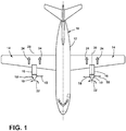
- FIG. 1 depicts an aircraft 10 having a fuselage 12 and wings 14 extending outward from the fuselage 12.
- the aircraft 10 can include at least one turbo-prop engine 16 coupled to the aircraft 10, shown as a set of engines 16 coupled with the opposing wings 14.
- the turbo-prop engine 16 can include a set of propeller blades 18 coupled with the engine 16 at a rotatable hub assembly 19, such that the engine 16 drives the rotation 22 of the propellers about an axis of rotation 20.
- the propeller blades 18 can further be configured or angled relative to the axis of rotation 20 such that the rotation 22 of the propeller blades 18 generates thrust (illustrated as arrow 24) for the aircraft 10.
- embodiments of the disclosure can include any number of engines 16 or propeller blades 18, or any placement of the engine 16 or blades 18 relative to the aircraft. Additionally, the rotation 22 of the propeller blades 18 is provided for understanding of the embodiments of the disclosure. Embodiments of the disclosure can include alternative directions of rotation 22 of the propeller blades 18, or embodiments wherein a set of turbo-prop engines 16 rotate propeller blades 18 in the same or opposing directions.
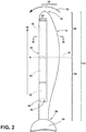
- FIG. 2 illustrates an example embodiment of the propeller blade 18 and hub 19, in accordance with various aspects described herein.
- the propeller blade 18 includes a total radial length 25 and defines a radial direction 26 extending radially outward from a blade root 28, wherein the blade 18 couples with the rotatable hub assembly 19, to a blade tip 30.
- the radial direction 26 extends normally to the rotatable hub assembly 19.
- the propeller blade 18 can also include a radially inner region 32 located between the blade root 28 and approximately fifty percent of the total radial length 25. The fifty percent of the total radial length 25 is illustrated as dotted line 34.
- a radially outer region 36 located between the radially inner region 32 and the blade tip 30.
- the radially inner region 32 is described as located between the blade root 28 and approximately fifty percent of the total radial length 25 of the blade 18, alternative configurations of the blade 18 can include that the inner region 32 is defined to include more or less of the total radial length of the blade 18.
- the radially outer region 36 can include approximately fifty to seventy percent of the total radial length 25 of the blade 18 in the radial direction 26.
- the example described includes a radially inner region 32 located between the blade root 28 and approximately fifty percent of the total radial length 25, non-limiting embodiments of the disclosure can be included wherein the radially inner region 32 is located between the blade root 28 and approximately thirty percent of the total radial length 25.
- non-limiting embodiments can include configurations wherein the radially outer region 36 can include approximately thirty to seventy percent of the total radial length 25 of the blade 18.
- At least a portion of a leading edge 38 of the propeller blade 18, can include a coating 40, for example, extending from the leading edge 38 along at least a portion 37 of a total chord length 39 of the blade 18.
- leading edge of the propeller blade 18 includes the edge of the blade 18 extending parallel with the radial direction 26 of the blade 18, and leading the blade 18 in the direction of rotation 22.
- chord length is the length of the blade 18 normal to the radial direction 26 of the blade 18.
- the coating 40 can be disposed on the propeller blade 18 and extend from the leading edge 38 along at least a portion 37 of the total chord length 39.
- the coating 40 has not been shown as being included on an entirety of the total chord length 39, it will be understood that it can be. Further, the coating 40 can extend over at least a portion of the total radial length 25 including at least a portion of the inner region 32 and the outer region 36. While the coating 40 has not been shown as being included along an entirety of the total radial length 25, it will be understood that it can be.
- the propeller blade 18 can further include at least one blade substrate.
- a first blade substrate 42 and a second blade substrate 44 have been illustrated as being located along the leading edge 38 of at least a portion of the inner region 32.
- the first blade substrate 42 has been illustrated as being positioned radially inward from the second blade substrate 44, with respect to the radial direction 26.
- the propeller blade 18 can additionally include a third blade substrate 46 located along the leading edge 38 of at least a portion of the outer region 36.
- the first, second, and third substrates 42, 44, 46 can define a respective first, second, and third color, wherein the first, second, and third colors can be similar to, different from, visually distinguishable from, or selected based on the other substrate 42, 44, 46 colors.
- the first substrate 42 color can be blue
- the second substrate 44 color can be red
- the third substrate 46 color can be green.
- the first, second, or third substrates 42, 44, 46 can be included in the propeller blade 18 itself or can alternatively be included as a portion of the coating 40.
- the substrate 42, 44, 46 could be manufactured from colored neoprene rubber.
- first and the second substrates 42, 44 are illustrated within the inner region 32 and a third substrate 46 is illustrated within the outer region 36 of the propeller blade 18, it will be understood that this need not be the case.
- Embodiments of the disclosure can be included wherein a first set of substrates can be included in the inner region 32, and a second set of substrates can be included in the outer region 36. This can include that the inner region 32 and the outer region 36 each include a single separate substrate.
- the coating 40 can be manufactured, configured, or selected to include icephobic material 48 or an icephobic surface, that is, a material or surface having the ability to at least partially repel ice or prevent ice formation.
- the icephobic material 48 can include icephobic characteristics due to a certain topographical structure of the surface of the material 48; however, additional compositional, configurational, or physical qualities can be included, incorporated into, or otherwise accounted for in the icephobic characteristics of the material 48.
- the coating 40 can also be disposed upon the propeller blade 18 such that the coating 40 at least partially overlies the substrates 42, 44, 46 along the leading edge 38 of the blade 18.
- the coating 40 having the icephobic material 48 can define a fourth color, which can, for example, be different from at least a subset of the first, second, and third substrate 42, 44, 46 colors.
- the coating 40 can be selected to be visually distinguishable from all of the other substrate 42, 44, 46 colors, or can be clear or semi-transparent, or a combination thereof.
- the transparency of the coating 40 can be manufactured, selected, or configured such that the disposition of the coating 40 over the respective substrates 42, 44, 46 at least partially obscures the colors of the corresponding substrates 42, 44, 46.
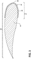
- FIG. 3 illustrates a cross section view of the propeller blade 18 taken along line III-III of FIG. 2 .
- the coating 40 extends along the leading edge 38 of the propeller blade 18.
- the coating 40 can be disposed upon the leading edge 38 and can extend from the leading edge 38 to a portion 37 of the total chord length 39 of the propeller blade 18.
- the portion 37 can be approximately twenty-five percent along the total chord length 39 of the blade 18.
- Alternative lengths of the coating 40 are also contemplated.
- the cross section view of FIG. 3 has been illustrated to represent one example configuration of the coating 40 relative to the radially outer region 36 of the propeller blade 18. While not shown for brevity, the cross-section view of FIG.
- the coating 40 can be applicable with respect to the coating 40 applied to the radially inner region 32.
- embodiments of the disclosure can be included wherein, for example, the amount of coating 40, or the amount of icephobic material 48 varies along the radial length of the propeller blade 18.
- the thickness of the coating 40 or icephobic material 48 can decrease with the increasing radius of the blade 18 from the blade root 28.
- the efficiency of the coating 40 or icephobic material 48 (that is, the ability to reduce, prevent, or shed ice build-up or growth) can increase with the increasing radius of the blade 18 from the blade root 28.
- the coating 40 can be applied to the propeller blade 18 such that the radially inner region 32 of the propeller blade 18 can reduce, prevent, or shed ice build-up or growth better than the radially outer region 36.
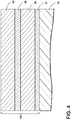
- FIG. 4 illustrates an alternative example coating 140, wherein the alternative example coating 140 includes a set or arrangement of layers applied to or disposed upon the propeller blade 18.
- the coating 140 can include a first layer 52 of adhesive provided directly adjacent the surface of the propeller blade 18.
- a second layer 54 can comprise a polymer, and can be applied to or disposed upon the adhesive layer 52.
- the second polymer layer 54 can further comprise a set of rubber materials such as neoprene.
- the second polymer layer 54 can have a thickness in the range 0.5 millimeter (mm) to 1.0 mm.
- a third layer 56 can comprise a tie coat, and can be applied to or disposed upon the second layer 54 to provide a suitable surface for bonding the icephobic material 48 to the coating 140.
- the third layer 56 can have a thickness on the order of 1 micrometer. In one exemplary configuration, the thickness of the icephobic material 48 layer can be approximately 3 mm.
- the coating 140 can be applied or otherwise mounted to the propeller blade 18 in any suitable manner.
- the individual layers 52, 54, 56, 48 of the coating can be independently secured to the propeller blade 18 or the other layers in a sequential manner. Alternatively, a subset of the individual layers 52, 54, 56, 48 can be secured to adjacent layers and then secured to the blade 18.
- the second layer 54 can be colored or configured to include the respective first, second, or third colors.
- the second layer 54 can include the respective first, second, or third substrates 42, 44, 46, depending on the position of the coating 40, 140 with respect to the radial length of the propeller blade 18, as explained herein.
- the wear or wearing away of the icephobic material 48 layer and the third tie coat layer 56 can expose the second layer 54 to provide an indication of wear of the icephobic material 48 layer.
- the wear or wearing away of the icephobic material 48 layer, and any other intervening layers can expose the respective first, second, or third substrates 42, 44, 46 to provide an indication of wear of the icephobic material 48 layer.
- embodiments of the disclosure can include a set of identifiable or distinguishable characteristics of the first, second, or third substrates 42, 44, 46, wherein the identifiable or distinguishing characteristics of the substrates 42, 44, 46 are different from the coating 40, 140.
- non-limiting exemplary characteristic such as electrical conduction, electrical isolation, capacitance, magnetic strength, or texture can distinguish the substrates 42, 44, 46 from the coating 40, 140 such that wear or wearing away of the icephobic material 48 layer exposes the distinguishing characteristic, compared with the coating 40, 140.
- non-visual indicators or characteristics can be incorporated into the contrasting qualities of the substrates 42, 44, 46 and coating 40, 140.
- the radial extent of the coating 40, 140 or icephobic material 48 can be chosen or selected to provide a low cohesion for ice where it is needed, such as relative to the radially inner region 32 of the blade.
- the radially outer region 36 of the propeller blade 18, when rotated, can be subjected to high enough rotational forces to cause ice to self-shed from coated or uncoated portions of the blade surface.
- the radially outer region 36 can include a portion of the propeller blade 18 wherein the rotational forces on the blade, in use, remove ice from a coated or an uncoated portion of the blade 18.
- the coating 40, 140 can have a cohesive coefficient which varies along the length of the blade, reflecting the fact that the rotational forces increase linearly with radius.
- the cohesive coefficient can increase with increasing radius, whereby the radially inner region 32 has the highest propensity for shedding ice. This can be achieved by the use of different icephobic materials 48 along the radial length of the coating 40, 140. In this way, it is possible to reduce the cost of the coating by only using the more costly icephobic materials 48 in the radially inner region 32.
- the thickness of the coating 40, 140 can vary along the total radial length 25 of the propeller blade 18, or the efficiency of the coating 40, 140 or icephobic material 48 can vary with the increasing radius of the blade 18.
- ice can accumulate on the propeller blades 18 until such time as the ice mass is sufficient to cause self-shedding under the action of the centrifugal forces on the ice which result from the rotation 22 of the propeller blades 18.
- the force exerted by the ice mass can be equivalent to the weight of the ice, multiplied by the radial location of the ice on the propeller blade 18, multiplied by the square of the rotational speed of the propeller blade 18.
- the amount of ice that has to build up at any specific radius of the propeller blade 18 to overcome the cohesive bond between the ice and the blade also varies. Nearer to the blade tip 30, the centrifugal forces can be high enough to prevent significant build-up of ice without any icephobic material 48 or coating 40, 140.
- the rotational speed of the propeller blade 18 can be of the order of 850 rotations per minute, whereby the centrifugal field outside a radius of 1.39 meters (55 inches) can shed ice from the blade surface without icephobic material 48 or coating 40, 140. Where the acceleration of the ice due to the rotation of the propeller blade 18 exceeds 1100 times the force of gravity, the ice tends to self-shed from the blade surface without any icephobic material 48 or coating 40, 140.
- the coating 40, 140 being a passive system, if the coating 40, 140 is damaged, worn away, or worn thin, the coating 40, 140 can lose effectiveness in reducing build-up, reducing accumulation, or enabling the shedding of ice.
- impact(s) from foreign object(s) can wear away, chip, or remove at least a portion of the coating 40, 140, the icephobic material 48, or various layers thereof.
- Embodiments of the disclosure provide for a propeller blade 18 wherein damage to or wearing away of the icephobic material 48 or the coating 40, 140 can be readily identified by way of a visual inspection due to the contrast of the fourth color (e.g.
- the coating 40, 140 or icephobic material 48 color relative to the underlying first, second, or third color (e.g. the colors of the respectively positioned first substrate 42, second substrate 44, or third substrate 46).
- first, second, or third color e.g. the colors of the respectively positioned first substrate 42, second substrate 44, or third substrate 46.
- embodiments of the propeller blade 18 are included wherein the color of the icephobic material 48 or coating 40, 140 is selected to visually indicate wear in the icephobic material 48 or coating 40, 140 by revealing the contrasting color of the substrate 42, 44, 46 underneath.
- the substrates 42, 44, 46 can be included in the propeller blade 18 or the coating 40, 140 itself, for example, as the second layer 54.
- the amount of damage to the icephobic material 48 or coating 40, 140 can be visually indicated or visually identified by revealing at least a portion of the underlying colors, for example, including a color gradient toward the underlying color to indicate the level or amount of wearing or damage.
- Embodiments of the disclosure described herein can further include configurations wherein the amount or level of wearing or damage to the icephobic material 48 or coating 40, 140 is visually identifiable or distinguishable between the different substrates 42, 44, 46 when the substrate 42, 44, 46 colors are different. For example, visually identifying the known first color, or a gradient of the known first color, on a portion of the propeller blade 18 indicates the wearing relative to the first substrate 42, compared with visually identifying the known second color, or gradient thereof, indicating the wearing relatives to the second substrate 44.
- a visualizer such as a maintenance member can rapidly determine the amount or level of damage or wear to the icephobic material 48 or coating 40, 140 by way of identifying the underlying colors and the location of the damage or wear relative to the length of the propeller blade 18.
- the visualizer can, for example, compare the amount or level of damage or wear to a visual inspection criteria corresponding with, for example, a predetermined set of icephobic material 48 or coating 40, 140 wear thresholds.
- the visual inspection criteria can include a color chart or card that the visualizer can hold proximate to the damage or wear to visually compare the amount of wear with the criteria or set of wear thresholds.
- a maintenance operation action can be initiated to, for example, reapply icephobic material 48 or coating 40, 140 to the worn portion, or removal or replacement of the propeller blade 18 or coating 40, 140.
- Embodiments of the disclosure can yet further include multiple visual inspection criteria or sets of wear thresholds corresponding with or relative to the individual substrates 42, 44, 46.
- the first or second substrates 42, 44, or the corresponding visual inspection criteria can be configured to tolerate or accept a respective first amount of wear and a second amount of wear.
- the first amount of wear can be different from the second amount of wear.
- the visual inspection criteria can be different for a subset of the substrates 42, 44, 46 to correspond with a varying level of acceptable wear or damage for the corresponding substrate 42, 44, 46.
- FIG. 5 illustrates a flow chart demonstrating a method 100 of inspecting a propeller blade 18.
- the method 100 begins by inspecting, such as visually inspecting, the radially inner region of the propeller blade at 110 and inspecting, such as visually inspecting, the radially outer region of the blade at 120.
- the method 100 then proceeds to identify a portion of the propeller blade at 130 wherein a contrasting color corresponding with a known color of an underlying substrate 42, 44, 46 has been revealed.
- the method 100 can then include comparing the portion of the propeller blade 18 identified at 130 to visual inspection criteria at 150.
- each substrate 42, 44, 46 has corresponding individual visual inspection criteria, or wherein a set of worn propeller blade portions are identified
- each substrate 42, 44, 46 or worn portion identified can be compared with its respective visual inspection criteria 150.
- the method 100 proceeds to initiating at least one of maintenance or replacement of the propeller blade at 160.
- the term "satisfy" the visual inspection criteria is used herein to mean that the portion of the propeller blade identified satisfies the visual inspection criteria, such as being visually equal to, visually indistinguishable from, or having a color gradient indicating more of the underlying substrate color, compared with a color gradient threshold criteria or a subset of criteria. It will be understood that such a determination may easily be altered to be satisfied by a positive/negative comparison, greater than/less than comparison or a true/false comparison. As described above, maintenance can include reapplying the icephobic material 48 or coating 40 to the identified portions of the propeller blade 18 satisfying the visual inspection criteria.
- the sequence depicted is for illustrative purposes only and is not meant to limit the method 100 in any way as it is understood that the portions of the method can proceed in a different logical order, additional or intervening portions can be included, or described portions of the method can be divided into multiple portions, or described portions of the method can be omitted without detracting from the described method.
- the radially outer region 36 can be inspected prior to the radially inner region 32.
- FIG. 6 illustrates an example propeller blade 18 wherein portions of the coating 40, 140 has been damaged or worn away.
- damage or wear to a first portion of the coating 40, 140 within the radially inner region 32 reveals or exposes the second substrate 44 having a first identifiable color.
- damage or wear to a second portion 166 of the coating 40, 150 within the radially outer region 36 reveals or exposes the third substrate 46 having a second identifiable color 168.
- the first identifiable color 164, the second identifiable color 168, and the color of the coating 40, 140 can be visually distinguishable from one another.
- the illustrated example of FIG. 6 is provided for ease of understanding the visual distinctions between the respective first and second identifiable colors 164, 168 and the color of the coating 40, 140. Actual damage or wear to the coating 40, 140 can be different than illustrated.
- embodiments of the disclosure having non-visual indicators or characteristics can include inspecting the regions of the propeller blade to identify portions of the blade having the non-visual indicator, and wherein the inspection criteria can include measureable qualities or quantities of the non-visual indicators compared with the coating.
- the inspecting or identifying can be accomplished using non-visual cues such as the conductivity, or other examples explained herein.
- the inspecting or identifying can include utilizing a sensor configured to optically compare a portion of the propeller blade with the inspection criteria and make an automated determination based on the comparison of the sensed or measured reading with the inspection criteria.
- the sensor can include an optical sensor configured to sense or measure the color of the portion of the propeller to visually inspect the propeller blade and compare the inspected portion with a visual inspection criteria.
- the embodiments disclosed herein provide a propeller blade 18 and method of inspecting a propeller blade 18 wherein wear or damage to the icephobic material or coating can be visually identified based on contrasting colors between the icephobic material or coating color and the underlying substrate color.
- One advantage that can be realized is that elements of the present disclosure can reduce accumulation or shed accumulation of ice from the propeller blade, by way of the icephobic material, without the need for, or reducing the need or robustness of alternative deicing methods or elements for the propeller blades, such as electrical heaters.
- electrical heaters By reducing or eliminating the need for electrical heaters, embodiments of the disclosure can reduce the demand on the aircraft electrical system for providing electrical power for propeller deicing.
- the reduction in the number of required elements in the system gives both technical and commercial benefits, improving reliability and maintainability, and also saving both initial acquisition and ongoing maintenance costs.
- the elements of the present disclosure further reduce the cohesive bond strength between the ice and the propeller blade by way of the icephobic material, such that the ice does not accumulate on the propeller blades.
- the aerodynamic efficiencies of the propellers increase, and the operable range of the aircraft can be improved or increased.
- Yet another advantage of the elements of the present disclosure is that wear or damage to the icephobic material or coating can be readily identified by visually inspecting the blade to contrasting or known substrate colors revealed through the coating. The visual inspection can be rapidly completed due to the contrasting colors, and where needed, applicable visual inspection criteria can be referenced and compared with any worn areas of the blade.
- a gradient of substrate color on a portion of the propeller blade can indicate upcoming maintenance, or provide an estimate of when the icephobic material or coating will need to be replaced in the future.
- the rapid visual inspection can quickly determine which area or portion of the propeller blade includes damage or wear to the icephobic material or coating, and which visual inspection criteria should be applied for comparison. Stated another way, the acceptable levels of wear or damage can vary across the length of the propeller blade and the different colored substrates allow for visually differentiating what inspection criteria is appropriate for the different portions of the blade. Since maintenance members are able to specify and apply different criteria to different portions of the propeller blade, it will be possible to extend propeller blade uptime. Extending propeller blade uptime results in reduced blade maintenance costs and increased productivity for the aircraft.
Landscapes
- Engineering & Computer Science (AREA)
- Aviation & Aerospace Engineering (AREA)
- Manufacturing & Machinery (AREA)
- Transportation (AREA)
- Structures Of Non-Positive Displacement Pumps (AREA)
- Coating Apparatus (AREA)
- Paper (AREA)
- Wind Motors (AREA)
- Turbine Rotor Nozzle Sealing (AREA)
Applications Claiming Priority (1)
| Application Number | Priority Date | Filing Date | Title |
|---|---|---|---|
| GB1601676.8A GB2546976B (en) | 2016-01-29 | 2016-01-29 | Propeller blades having icephobic coating with separate substrate portions defining different colours |
Publications (2)
| Publication Number | Publication Date |
|---|---|
| EP3199452A2 true EP3199452A2 (de) | 2017-08-02 |
| EP3199452A3 EP3199452A3 (de) | 2017-09-13 |
Family
ID=55590417
Family Applications (1)
| Application Number | Title | Priority Date | Filing Date |
|---|---|---|---|
| EP17153387.0A Withdrawn EP3199452A3 (de) | 2016-01-29 | 2017-01-26 | Propellerblätter mit eisabstossender beschichtung |
Country Status (7)
| Country | Link |
|---|---|
| US (1) | US10486795B2 (de) |
| EP (1) | EP3199452A3 (de) |
| JP (1) | JP2017132456A (de) |
| CN (1) | CN107054627A (de) |
| BR (1) | BR102017001720A2 (de) |
| CA (1) | CA2955440A1 (de) |
| GB (1) | GB2546976B (de) |
Cited By (2)
| Publication number | Priority date | Publication date | Assignee | Title |
|---|---|---|---|---|
| CN111792039A (zh) * | 2020-06-29 | 2020-10-20 | 山东大学 | 一种用于飞机机翼的除冰装置、系统及方法 |
| EP4147795A1 (de) * | 2021-09-13 | 2023-03-15 | Goodrich Corporation | Überwachung von beschichtungen mit geringer eisadhäsion |
Families Citing this family (5)
| Publication number | Priority date | Publication date | Assignee | Title |
|---|---|---|---|---|
| CN108248077A (zh) * | 2017-12-04 | 2018-07-06 | 惠阳航空螺旋桨有限责任公司 | 一种桨叶除冰加热片成型方法 |
| CN111017206A (zh) * | 2019-12-23 | 2020-04-17 | 上海自图新材料科技有限公司 | 一种直升机桨叶的防护方法 |
| US12037096B1 (en) | 2022-01-31 | 2024-07-16 | Brunswick Corporation | Marine propeller |
| US11827323B1 (en) | 2022-01-31 | 2023-11-28 | Brunswick Corporation | Marine propeller |
| US11912389B1 (en) | 2022-01-31 | 2024-02-27 | Brunswick Corporation | Marine propeller |
Family Cites Families (16)
| Publication number | Priority date | Publication date | Assignee | Title |
|---|---|---|---|---|
| US2434208A (en) * | 1945-08-17 | 1948-01-06 | Gen Motors Corp | Aeroplane propeller having an ice preventing coating |
| AU8072998A (en) * | 1997-06-16 | 1999-01-04 | Trustees Of Dartmouth College | Systems and methods for modifying ice adhesion strength |
| WO2000066889A1 (en) * | 1999-04-30 | 2000-11-09 | Office Of Technology Liaison | Minimization of motion smear: an approach to reducing avian collisions with wind turbines |
| ES2655908T3 (es) * | 2005-12-14 | 2018-02-22 | Hontek Corporation | Método para proteger y reparar una superficie de perfil de ala |
| US20080159870A1 (en) * | 2006-12-14 | 2008-07-03 | Hontek Corporation | Method and coating for protecting and repairing an airfoil surface using molded boots, sheet or tape |
| US20120156049A1 (en) * | 2005-12-14 | 2012-06-21 | Hong Shek C | Method and coating for protecting and repairing an airfoil surface |
| US8052387B2 (en) * | 2007-12-12 | 2011-11-08 | Hong Fu Jin Precision Industry (Shenzhen) Co., Ltd. | Cooling fan |
| US7875354B2 (en) * | 2008-03-18 | 2011-01-25 | General Electric Company | Erosions systems and components comprising the same |
| GB2483672B (en) * | 2010-09-15 | 2017-01-18 | Ge Aviat Systems Ltd | Propeller blades having icephobic coating |
| US9587645B2 (en) * | 2010-09-30 | 2017-03-07 | Pratt & Whitney Canada Corp. | Airfoil blade |
| US20120163981A1 (en) * | 2010-12-22 | 2012-06-28 | Hong Shek C | Method and coating for protecting and repairing an airfoil surface |
| US8834126B2 (en) * | 2011-06-30 | 2014-09-16 | United Technologies Corporation | Fan blade protection system |
| US8851858B2 (en) * | 2011-08-26 | 2014-10-07 | Ge Aviation Systems Limited | Propeller blades having icephobic coating |
| GB201122082D0 (en) * | 2011-12-22 | 2012-02-01 | Rolls Royce Deutschland | Method and apparatus for inspection of components |
| US10099772B2 (en) * | 2014-10-31 | 2018-10-16 | Hamilton Sundstrand Corporation | Ice-shedding spinner for ram air turbine |
| WO2016206702A1 (en) * | 2015-06-25 | 2016-12-29 | Patentco Aps | Coating system for coating a surface of a substrate |
-
2016
- 2016-01-29 GB GB1601676.8A patent/GB2546976B/en not_active Expired - Fee Related
-
2017
- 2017-01-09 US US15/401,140 patent/US10486795B2/en active Active
- 2017-01-17 JP JP2017005535A patent/JP2017132456A/ja active Pending
- 2017-01-19 CA CA2955440A patent/CA2955440A1/en not_active Abandoned
- 2017-01-25 CN CN201710055890.XA patent/CN107054627A/zh active Pending
- 2017-01-26 EP EP17153387.0A patent/EP3199452A3/de not_active Withdrawn
- 2017-01-27 BR BR102017001720-6A patent/BR102017001720A2/pt not_active Application Discontinuation
Non-Patent Citations (1)
| Title |
|---|
| None |
Cited By (2)
| Publication number | Priority date | Publication date | Assignee | Title |
|---|---|---|---|---|
| CN111792039A (zh) * | 2020-06-29 | 2020-10-20 | 山东大学 | 一种用于飞机机翼的除冰装置、系统及方法 |
| EP4147795A1 (de) * | 2021-09-13 | 2023-03-15 | Goodrich Corporation | Überwachung von beschichtungen mit geringer eisadhäsion |
Also Published As
| Publication number | Publication date |
|---|---|
| GB2546976B (en) | 2020-01-08 |
| EP3199452A3 (de) | 2017-09-13 |
| GB2546976A (en) | 2017-08-09 |
| CA2955440A1 (en) | 2017-07-29 |
| BR102017001720A2 (pt) | 2017-08-08 |
| US10486795B2 (en) | 2019-11-26 |
| GB201601676D0 (en) | 2016-03-16 |
| US20170217565A1 (en) | 2017-08-03 |
| CN107054627A (zh) | 2017-08-18 |
| JP2017132456A (ja) | 2017-08-03 |
Similar Documents
| Publication | Publication Date | Title |
|---|---|---|
| US10486795B2 (en) | Propeller blades having icephobic coating | |
| CA1215858A (en) | Method and apparatus for prognosticating potential ice accumulation on a surface exposed to impact icing | |
| US11618575B2 (en) | Ice detector apparatus, system, and method | |
| CN102398674B (zh) | 具有防冰覆层的螺旋桨叶片 | |
| NL2010504C2 (en) | Use of ice-phobic coatings. | |
| US9352841B2 (en) | Virtual ice accretion meter display | |
| EP2910916A1 (de) | Gesamtlufttemperatursonde mit niedriger stirnseitiger Projektionsfläche | |
| CN110987284A (zh) | 一种用于飞翼式飞机的高可靠性全嵌入式大气数据系统 | |
| US20200189553A1 (en) | Method and system for monitoring the state of a brake of an aircraft | |
| US20100028151A1 (en) | Field Installable and Removable Helicopter Rotor Blade Vibration and Blade Tracking Device | |
| CN107264811A (zh) | 具有用于过冷大液滴结冰检测的传感器的气动除冰器 | |
| US8851858B2 (en) | Propeller blades having icephobic coating | |
| US8602361B2 (en) | Laminar flow monitor | |
| ES2829148T3 (es) | Una disposición de cojinetes y una turbina eólica | |
| EP4147795A1 (de) | Überwachung von beschichtungen mit geringer eisadhäsion | |
| US20140050581A1 (en) | Erosion protection system and method | |
| Neel Jr et al. | The effect of ice formations on propeller performance | |
| US20260062129A1 (en) | Method and System for Ice Detection | |
| EP2572982A1 (de) | Profil mit einem Kreislaufsteuersystem | |
| Jacobs et al. | Investigation of Extreme Leading-Edge Roughness on Thick Low-Drag Airfoils to Indicate Those Critical to Separation | |
| Gębura | Application of electric capacity measurements to detecting delamination in blades of helicopter’s lifting and auxiliary rotors | |
| Fisher Jr et al. | An experimental investigation of the helicopter rotor blade element airloads on a model rotor in the blade stall regime |
Legal Events
| Date | Code | Title | Description |
|---|---|---|---|
| PUAI | Public reference made under article 153(3) epc to a published international application that has entered the european phase |
Free format text: ORIGINAL CODE: 0009012 |
|
| AK | Designated contracting states |
Kind code of ref document: A2 Designated state(s): AL AT BE BG CH CY CZ DE DK EE ES FI FR GB GR HR HU IE IS IT LI LT LU LV MC MK MT NL NO PL PT RO RS SE SI SK SM TR |
|
| AX | Request for extension of the european patent |
Extension state: BA ME |
|
| PUAL | Search report despatched |
Free format text: ORIGINAL CODE: 0009013 |
|
| AK | Designated contracting states |
Kind code of ref document: A3 Designated state(s): AL AT BE BG CH CY CZ DE DK EE ES FI FR GB GR HR HU IE IS IT LI LT LU LV MC MK MT NL NO PL PT RO RS SE SI SK SM TR |
|
| AX | Request for extension of the european patent |
Extension state: BA ME |
|
| RIC1 | Information provided on ipc code assigned before grant |
Ipc: B64D 15/00 20060101ALI20170809BHEP Ipc: B64C 11/20 20060101AFI20170809BHEP |
|
| 17P | Request for examination filed |
Effective date: 20180313 |
|
| RBV | Designated contracting states (corrected) |
Designated state(s): AL AT BE BG CH CY CZ DE DK EE ES FI FR GB GR HR HU IE IS IT LI LT LU LV MC MK MT NL NO PL PT RO RS SE SI SK SM TR |
|
| 17Q | First examination report despatched |
Effective date: 20181119 |
|
| GRAP | Despatch of communication of intention to grant a patent |
Free format text: ORIGINAL CODE: EPIDOSNIGR1 |
|
| INTG | Intention to grant announced |
Effective date: 20190809 |
|
| STAA | Information on the status of an ep patent application or granted ep patent |
Free format text: STATUS: THE APPLICATION IS DEEMED TO BE WITHDRAWN |
|
| 18D | Application deemed to be withdrawn |
Effective date: 20191220 |