EP3199355A1 - Ink circulation device and printer - Google Patents
Ink circulation device and printer Download PDFInfo
- Publication number
- EP3199355A1 EP3199355A1 EP16189293.0A EP16189293A EP3199355A1 EP 3199355 A1 EP3199355 A1 EP 3199355A1 EP 16189293 A EP16189293 A EP 16189293A EP 3199355 A1 EP3199355 A1 EP 3199355A1
- Authority
- EP
- European Patent Office
- Prior art keywords
- ink
- heater
- vibration plate
- piezoelectric vibration
- temperature
- Prior art date
- Legal status (The legal status is an assumption and is not a legal conclusion. Google has not performed a legal analysis and makes no representation as to the accuracy of the status listed.)
- Withdrawn
Links
Images



Classifications
-
- B—PERFORMING OPERATIONS; TRANSPORTING
- B41—PRINTING; LINING MACHINES; TYPEWRITERS; STAMPS
- B41J—TYPEWRITERS; SELECTIVE PRINTING MECHANISMS, i.e. MECHANISMS PRINTING OTHERWISE THAN FROM A FORME; CORRECTION OF TYPOGRAPHICAL ERRORS
- B41J2/00—Typewriters or selective printing mechanisms characterised by the printing or marking process for which they are designed
- B41J2/005—Typewriters or selective printing mechanisms characterised by the printing or marking process for which they are designed characterised by bringing liquid or particles selectively into contact with a printing material
- B41J2/01—Ink jet
- B41J2/015—Ink jet characterised by the jet generation process
- B41J2/04—Ink jet characterised by the jet generation process generating single droplets or particles on demand
- B41J2/045—Ink jet characterised by the jet generation process generating single droplets or particles on demand by pressure, e.g. electromechanical transducers
- B41J2/04501—Control methods or devices therefor, e.g. driver circuits, control circuits
- B41J2/04563—Control methods or devices therefor, e.g. driver circuits, control circuits detecting head temperature; Ink temperature
-
- B—PERFORMING OPERATIONS; TRANSPORTING
- B41—PRINTING; LINING MACHINES; TYPEWRITERS; STAMPS
- B41J—TYPEWRITERS; SELECTIVE PRINTING MECHANISMS, i.e. MECHANISMS PRINTING OTHERWISE THAN FROM A FORME; CORRECTION OF TYPOGRAPHICAL ERRORS
- B41J2/00—Typewriters or selective printing mechanisms characterised by the printing or marking process for which they are designed
- B41J2/005—Typewriters or selective printing mechanisms characterised by the printing or marking process for which they are designed characterised by bringing liquid or particles selectively into contact with a printing material
- B41J2/01—Ink jet
- B41J2/015—Ink jet characterised by the jet generation process
- B41J2/04—Ink jet characterised by the jet generation process generating single droplets or particles on demand
- B41J2/045—Ink jet characterised by the jet generation process generating single droplets or particles on demand by pressure, e.g. electromechanical transducers
- B41J2/04501—Control methods or devices therefor, e.g. driver circuits, control circuits
- B41J2/04581—Control methods or devices therefor, e.g. driver circuits, control circuits controlling heads based on piezoelectric elements
-
- B—PERFORMING OPERATIONS; TRANSPORTING
- B41—PRINTING; LINING MACHINES; TYPEWRITERS; STAMPS
- B41J—TYPEWRITERS; SELECTIVE PRINTING MECHANISMS, i.e. MECHANISMS PRINTING OTHERWISE THAN FROM A FORME; CORRECTION OF TYPOGRAPHICAL ERRORS
- B41J2/00—Typewriters or selective printing mechanisms characterised by the printing or marking process for which they are designed
- B41J2/005—Typewriters or selective printing mechanisms characterised by the printing or marking process for which they are designed characterised by bringing liquid or particles selectively into contact with a printing material
- B41J2/01—Ink jet
- B41J2/135—Nozzles
- B41J2/14—Structure thereof only for on-demand ink jet heads
- B41J2/14201—Structure of print heads with piezoelectric elements
- B41J2/14233—Structure of print heads with piezoelectric elements of film type, deformed by bending and disposed on a diaphragm
-
- B—PERFORMING OPERATIONS; TRANSPORTING
- B41—PRINTING; LINING MACHINES; TYPEWRITERS; STAMPS
- B41J—TYPEWRITERS; SELECTIVE PRINTING MECHANISMS, i.e. MECHANISMS PRINTING OTHERWISE THAN FROM A FORME; CORRECTION OF TYPOGRAPHICAL ERRORS
- B41J2/00—Typewriters or selective printing mechanisms characterised by the printing or marking process for which they are designed
- B41J2/005—Typewriters or selective printing mechanisms characterised by the printing or marking process for which they are designed characterised by bringing liquid or particles selectively into contact with a printing material
- B41J2/01—Ink jet
- B41J2/17—Ink jet characterised by ink handling
- B41J2/175—Ink supply systems ; Circuit parts therefor
-
- B—PERFORMING OPERATIONS; TRANSPORTING
- B41—PRINTING; LINING MACHINES; TYPEWRITERS; STAMPS
- B41J—TYPEWRITERS; SELECTIVE PRINTING MECHANISMS, i.e. MECHANISMS PRINTING OTHERWISE THAN FROM A FORME; CORRECTION OF TYPOGRAPHICAL ERRORS
- B41J2/00—Typewriters or selective printing mechanisms characterised by the printing or marking process for which they are designed
- B41J2/005—Typewriters or selective printing mechanisms characterised by the printing or marking process for which they are designed characterised by bringing liquid or particles selectively into contact with a printing material
- B41J2/01—Ink jet
- B41J2/17—Ink jet characterised by ink handling
- B41J2/175—Ink supply systems ; Circuit parts therefor
- B41J2/17596—Ink pumps, ink valves
-
- B—PERFORMING OPERATIONS; TRANSPORTING
- B41—PRINTING; LINING MACHINES; TYPEWRITERS; STAMPS
- B41J—TYPEWRITERS; SELECTIVE PRINTING MECHANISMS, i.e. MECHANISMS PRINTING OTHERWISE THAN FROM A FORME; CORRECTION OF TYPOGRAPHICAL ERRORS
- B41J2/00—Typewriters or selective printing mechanisms characterised by the printing or marking process for which they are designed
- B41J2/005—Typewriters or selective printing mechanisms characterised by the printing or marking process for which they are designed characterised by bringing liquid or particles selectively into contact with a printing material
- B41J2/01—Ink jet
- B41J2/17—Ink jet characterised by ink handling
- B41J2/18—Ink recirculation systems
-
- B—PERFORMING OPERATIONS; TRANSPORTING
- B41—PRINTING; LINING MACHINES; TYPEWRITERS; STAMPS
- B41J—TYPEWRITERS; SELECTIVE PRINTING MECHANISMS, i.e. MECHANISMS PRINTING OTHERWISE THAN FROM A FORME; CORRECTION OF TYPOGRAPHICAL ERRORS
- B41J2/00—Typewriters or selective printing mechanisms characterised by the printing or marking process for which they are designed
- B41J2/005—Typewriters or selective printing mechanisms characterised by the printing or marking process for which they are designed characterised by bringing liquid or particles selectively into contact with a printing material
- B41J2/01—Ink jet
- B41J2/17—Ink jet characterised by ink handling
- B41J2/195—Ink jet characterised by ink handling for monitoring ink quality
-
- B—PERFORMING OPERATIONS; TRANSPORTING
- B41—PRINTING; LINING MACHINES; TYPEWRITERS; STAMPS
- B41J—TYPEWRITERS; SELECTIVE PRINTING MECHANISMS, i.e. MECHANISMS PRINTING OTHERWISE THAN FROM A FORME; CORRECTION OF TYPOGRAPHICAL ERRORS
- B41J2202/00—Embodiments of or processes related to ink-jet or thermal heads
- B41J2202/01—Embodiments of or processes related to ink-jet heads
- B41J2202/12—Embodiments of or processes related to ink-jet heads with ink circulating through the whole print head
Definitions
- Embodiments described herein relate generally to an ink circulation device and a printer.
- an ink circulation device for a circulation-type inkjet head corresponding to various kinds of ink, such as solvent ink, oil-based ink or water-based ink.
- ink such as solvent ink, oil-based ink or water-based ink.
- the ink is heated to adjust the viscosity thereof.
- the shape forming the appearance of the ink circulation device is constituted by a casing. If the ink inside the ink circulation device is heated with a heater mounted on the outer surface of the casing, as the casing is relatively thick, it is difficult to transmit heat generated by the heater to the ink, and there is a problem that the ink cannot be heated to a desired temperature.
- an ink circulation device comprising:
- a voltage is applied to the heater.
- the ink circulation device further comprises:
- the ink circulation device further comprises a pump for ink circulation.
- the invention also relates to a printer, comprising:
- the invention further relates to an ink circulation method within a printer, comprising:
- the method further comprises applying voltage to a heater while driving the piezoelectric vibration plate.
- the method further comprises:
- the method further comprises:
- the method further comprises using a pump for ink circulation.
- the Curie temperature of the piezoelectric vibration plate is 200 to 300 degrees centigrade.
- the temperature of the heater is one half the Curie temperature or less.
- the Curie temperature of the piezoelectric vibration plate is 200 to 300 degrees centigrade.
- the temperature of the heater is one half the Curie temperature or less.
- the Curie temperature of the piezoelectric vibration plate is 200 to 300 degrees centigrade and the temperature of the heater is one half the Curie temperature or less.
- an ink circulation device comprises a pressure chamber, a piezoelectric vibration plate, a valve, a heater and a connection section.
- the pressure chamber includes at least two flow holes through which ink flows.
- the piezoelectric vibration plate constitutes a part of a wall of the pressure chamber and is driven to increase or decrease an inner volume of the pressure chamber.
- the valve opens and closes at least one of the two flow holes.
- the heater is laminated on the piezoelectric vibration plate.
- the connection section connects the pressure chamber to an inkjet head.
- an ink circulation method within a printer involves driving a piezoelectric vibration plate constituting a part of a wall of a pressure chamber to increase or decrease an inner volume of the pressure chamber and thereby circulating ink therein; opening and closing at least one of two flow holes in the pressure chamber; and heating the piezoelectric vibration plate.
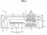
- a printer 1 As shown in Fig. 1 , a printer 1 according to the present embodiment is equipped with a feeding table 3, a carriage 4, and a maintenance unit 5 inside a housing 2.
- the feeding table 3 is slidably held by a guide rail for feeding 6 arranged inside the housing 2.
- the guide rail for feeding 6 linearly extends in a substantially horizontal direction.
- the feeding table 3 is moved in a direction along the guide rail for feeding 6 by a motor (not shown).
- a negative pressure generation device 7 for absorbing a sheet-like image receiving medium S such as a sheet to fix the image receiving medium S on the feeding table 3 is arranged in the feeding table 3.
- the feeding table 3, the guide rail for feeding 6, the motor and the negative pressure generation device 7 constitute a conveyance section 8 for conveying the image receiving medium S to an inkjet head 16 described later.
- the image receiving medium S is not limited to a paper, and it may be a film made of resin or metal or a plate made of wood.
- the carriage 4 is sidably held by a guide rail for scanning (not shown) arranged inside the housing 2.
- the guide rail for scanning linearly extends in a substantially horizontal direction orthogonal to the guide rail for feeding 6.
- the carriage 4 is moved in a direction along the guide rail for scanning through a conveyance belt 9 driven by a motor (not shown).
- a plurality of inkjet units 15 arranged along a scanning direction of the carriage 4 is loaded in the carriage 4.
- the inkjet unit 15 is equipped with an inkjet head 16 for injecting the ink I onto the image receiving medium S, an ink circulation device 17 of the present embodiment connected with the inkjet head 16 at the upper side of the inkjet head 16 and a unit control section (control section) 18 for controlling the inkjet head 16 and the ink circulation device 17.
- the inkjet unit 15 the number of which corresponds to the category of the ink I injected onto the image receiving medium S is loaded in the carriage 4.
- the ink I injected from each inkjet unit 15 may include transparent glossiness ink or special ink which develops color when irradiated with an infrared ray or an ultraviolet ray in addition to the ink having various colors such as cyan, magenta, yellow, black, white and the like.
- An ink cartridge (not shown) is connected with the ink circulation device 17 of each inkjet unit 15. These ink cartridges are arranged inside the housing 2.
- the ink circulation device 17 of each inkjet unit 15 and the ink cartridge are connected with each other through a flexible connection tube (not shown).
- a plurality of the inkjet units 15 is aggregately arranged above the carriage 4 and moves along the guide rail for scanning together with the carriage 4.
- the maintenance unit 5 covers the injection section of the inkjet head 16 for injecting the ink I to prevent evaporation of the ink I at the time a plurality of the inkjet units 15 and the carriage 4 return to a standby position at which the ink I is not injected from the inkjet head 16.
- the maintenance unit 5 appropriately cleans the contact portion of the inkjet head 16 with the image receiving medium S at the time a plurality of the inkjet units 15 returns to the standby position.
- a main control section 10 is connected with the motor, the negative pressure generation device 7, the maintenance unit 5 and each inkjet unit 15 to control them.
- the inkjet head 16 of each inkjet unit 15 is equipped with a plurality of nozzle sections (not shown) for injecting the ink I onto the image receiving medium S and actuators (not shown) arranged to face each nozzle section.
- the actuator is composed of, for example, a piezoelectric vibration plate using piezoelectric ceramic. If a signal is input to the actuator, the actuator increases the pressure of the ink I so that the ink I is injected from each nozzle section. With the injected ink I, the image receiving medium S is printed.
- the ink circulation device 17 of each inkjet unit 15 is equipped with a casing 21, an actuator unit for circulation 36A and an actuator unit for supply 36B which are mounted in the casing 21, valve bodies 38A, 38B, 39A and 39B and a connection section 40.
- the casing 21 is formed by, for example, carrying out die casting on aluminum.
- an ink supply chamber 22, an ink collection chamber 23, a supply pump housing chamber 24, a circulation pump housing chamber 25, an ink chamber 26, a communicating path 27, a replenishing path 28, and an inflow port 29 serving as internal spaces are formed.
- a well-known liquid surface sensor 31B for detecting a liquid surface of the ink I in the ink supply chamber 22 is mounted in the ink supply chamber 22.
- a well-known liquid surface sensor 31A for detecting a liquid surface of the ink I in the ink collection chamber 23 is mounted in the ink collection chamber 23.
- the liquid surface sensors 31A and 31B are connected with the unit control section 18 to send detection results of the liquid surface of the ink I to the unit control section 18.
- the upper part of the liquid surface of the ink I in the ink supply chamber 22 and the upper part of the liquid surface of the ink I in the ink collection chamber 23 respectively form air chambers.
- the pressure sensor 32 communicates with each forgoing air chamber to detect the pressure of the two ink chambers 22 and 23.
- the pressure adjustment section 33 adjusts the pressure of the inside of the casing 21 so as to properly keep surface pressure of each nozzle section of the inkjet head 16 based on the detection result of the pressure sensor 32.
- the ink supply chamber 22 communicates with the communicating path 27.
- An end of the replenishing path 28 forms a pipe line of a replenishing port 28a arranged at the outer surface of the casing 21 and opens to the outside of the casing 21.
- the replenishing port 28a is connected with the foregoing ink cartridge via a connection tube.
- the replenishing path 28 communicates with the supply pump housing chamber 24 via a flow hole 24a penetrating a wall which partitions the replenishing path 28 and the supply pump housing chamber 24.
- the valve body 38A serving as a well-known check valve is mounted.
- the valve body 38A opens and closes the flow hole 24a to allow the flow of the ink I from the replenishing path 28 to the supply pump housing chamber 24 through the flow hole 24a and regulate the flow of the ink I from the supply pump housing chamber 24 to the replenishing path 28.
- the supply pump housing chamber 24 communicates with the ink chamber 26 via a flow hole 24b penetrating a wall which partitions the ink chamber 26 and the supply pump housing chamber 24.
- the valve body 38B is mounted in the wall.
- the valve body 38B opens and closes the flow hole 24b to allow the flow of the ink I from the supply pump housing chamber 24 to the ink chamber 26 through the flow hole 24b and regulate the flow of the ink I from the ink chamber 26 to the supply pump housing chamber 24.
- the ink chamber 26 communicates with the communicating path 27 via a filter 30.
- the ink collection chamber 23 communicates with the inflow port 29.
- the inflow port 29 communicates with the circulation pump housing chamber 25 via a flow hole 25a penetrating a wall which partitions the inflow port 29 and the circulation pump housing chamber 25.
- the valve body 39A is mounted in the wall. The valve body 39A opens and closes the flow hole 25a to allow the flow of the ink I from the inflow port 29 to the circulation pump housing chamber 25 through the flow hole 25a and regulate the flow of the ink I from the circulation pump housing chamber 25 to the inflow port 29.
- the circulation pump housing chamber 25 communicates with the ink chamber 26 via a flow hole 25b penetrating a wall which partitions the ink chamber 26 and the circulation pump housing chamber 25.
- the valve body 39B is mounted in the wall. The valve body 39B opens and closes the flow hole 25b to allow the flow of the ink I from the circulation pump housing chamber 25 to the ink chamber 26 through the flow hole 25b and regulate the flow of the ink I from the ink chamber 26 to the circulation pump housing chamber 25.
- the components of the actuator unit for circulation 36A are the same as those of the actuator unit for supply 36B except that the actuator unit for supply 36B is not equipped with a heater 44A and a heater temperature sensor 46A described later.
- the component of the actuator unit for circulation 36A is indicated by adding a capital letter "A" to the number
- the component of the actuator unit for supply 36B corresponding to that of the actuator unit for circulation 36A is indicated by adding a capital letter "B" to the same number as the actuator unit for circulation 36A.
- a piezoelectric vibration plate 42A and a piezoelectric vibration plate 42B shown in Fig. 3 are the same components.
- the actuator unit for circulation 36A is formed into a laminated structure by laminating a liquid contact sheet 41A, the piezoelectric vibration plate 42A, an insulating sheet 43A, the heater 44A, an insulating sheet 45A and a heater temperature sensor (temperature sensor) 46A in order in a mutually attached manner.
- the liquid contact sheet 41A is made of resin which contacts with the ink I in a pressure chamber for circulation 25c described later.
- PI polyimide
- the liquid contact sheet 41A, the piezoelectric vibration plate 42A and the insulating sheets 43A and 45A are formed in a circular plate shape.
- the piezoelectric vibration plate 42A is a unimorph type piezoelectric vibration plate composed of a metal plate 42aA and a piezoelectric ceramic 42bA.
- the material forming the metal plate 42aA is, for example, brass.
- the material forming the piezoelectric ceramic 42bA is, for example, PZT (lead zirconate titanate).
- the piezoelectric ceramic 42bA is subjected to Ni/Au-plated electrode on upper and lower surfaces thereof and has a piezoelectric property by a polarization processing.
- An end of a lead wire for vibration plate 42cA is respectively connected with the metal plate 42aA and the piezoelectric ceramic 42bA through a solder portion 42dA.
- the lead wire for vibration plate 42cA is a cable for applying AC voltage generated by a pump driving circuit 57A described later of the unit control section 18 to the piezoelectric vibration plate 42A.
- the heater 44A is configured by respectively connecting a lead wire for heater 44bA with both ends of a heater main body 44aA which is formed into a bellows shape.
- the heater main body 44aA is a resistor, formed by a heating wire such as stainless steel, nichrome wire and the like, of which the value of the electrical resistance is several ⁇ (ohms) to several thousand ⁇ .
- the heater main body 44aA is formed into a bellows shape; however, the shape of the heater main body 44aA is not particularly limited as long as it is a shape which can increase the length of the heater main body 44aA arranged in a certain area.
- the heater main body 44aA can be formed into a spiral shape or the like other than the bellows shape.
- the heater main body 44aA generates heat if a voltage from the unit control section 18 is applied.
- the generated heat is used to heat the ink I in the pressure chamber for circulation 25c described later via the insulating sheet 43A, the piezoelectric vibration plate 42A and the liquid contact sheet 41A.
- the lead wire for heater 44bA of the heater 44A and the lead wire for vibration plate 42cA of the piezoelectric vibration plate 42A are arranged in different directions of the circumferential direction the piezoelectric vibration plate 42A. With such a configuration, it can be suppressed that the heater 44A contacts with the solder portion 42dA.
- the heater 44A is arranged between the insulating sheet 43A and the insulating sheet 45A.
- the insulating sheets 43A and 45A are covers for covering the heater 44A by sandwiching the heater 44A therebetween.
- the insulating sheets 43A and 45A are formed by PI sheets.
- Notches 43aA and 45aA for avoiding the solder portion 42dA are arranged in the insulating sheets 43A and 45A. Through arranging the solder portion 42dA in the notches 43aA and 45aA, the thickness of the whole of the actuator unit for circulation 36A can be suppressed.
- a thermistor can be suitably used in the heater temperature sensor 46A.
- the heater temperature sensor 46A is affixed or laminated on the piezoelectric vibration plate 42A across the insulating sheets 43A and 45A and the heater 44A.
- the heater temperature sensor 46A is connected to the unit control section 18 to transmit the detected temperature of the heater 44A to the unit control section 18.
- an epoxy-based or silicone-based adhesive can be used or an adhesive tape can be used.
- the actuator unit for circulation 36A with such a configuration is formed into a thin plate shape of which the thickness of the whole is 500 ⁇ 1000 ⁇ m (micrometers). Thus, the heat generated by the heater 44A can be transmitted to the ink I with a little loss.
- the thickness of the actuator unit for circulation 36A is sufficiently thinner than that of the wall of the casing 21.
- the actuator unit for circulation 36A is mounted in such a manner that the actuator unit for circulation 36A can be moved at both sides of the thickness direction of the actuator unit for circulation 36A in the circulation pump housing chamber 25.
- the space of the circulation pump housing chamber 25 at the flow holes 25a and 25b side with respect to the actuator unit for circulation 36A, the wall of the casing 21 surrounding the space and the actuator unit for circulation 36A constitute a pressure chamber for circulation (pressure chamber) 25c.
- the piezoelectric vibration plate 42A of the actuator unit for circulation 36A constitutes a part of the wall of the pressure chamber for circulation 25c.
- a pump for ink circulation 48 for circulating the ink I in the ink circulation device 17 and the inkjet head 16 and including the pressure chamber for circulation 25c and the valve bodies 39A and 39B is constituted.
- the piezoelectric vibration plate 42A is driven to move the actuator unit for circulation 36A in the thickness direction thereof to increase or decrease the volume of the inside of the pressure chamber for circulation 25c.
- the actuator unit for supply 36B is mounted in such a manner that the actuator unit for supply 36B can be moved at both sides of the thickness direction of the actuator unit for supply 36B in the supply pump housing chamber 24.
- the space of the supply pump housing chamber 24 at the flow holes 24a and 24b side with respect to the actuator unit for supply 36B, the wall of the casing 21 surrounding the space and the actuator unit for supply 36B constitute a pressure chamber for supply 24c.
- the piezoelectric vibration plate 42B of the actuator unit for supply 36B constitutes a part of the wall of the pressure chamber for supply 24c.
- a pump for ink supply 49 for supplying the ink I to the ink circulation device 17 from the outside is constituted by the pressure chamber for supply 24c and the valve bodies 38A and 38B.
- the piezoelectric vibration plate 42B is driven to move the actuator unit for supply 36B in the thickness direction thereof to increase or decrease the volume of the inside of the pressure chamber for supply 24c.
- two flow holes 25a and 25b are formed in the pressure chamber for circulation 25c; however, the number of the flow holes formed in the pressure chamber for circulation 25c is not particularly limited, and may be three or more, which is the same as the pressure chamber for supply 24c.
- the inkjet unit 15 may be not equipped with the valve bodies 38B and 39B. Even in such a configuration, the ink I can flow only in one direction.
- connection section 40 includes an ink supply pipe 52 and an ink return pipe 53.
- One end of the ink supply pipe 52 communicates with the ink supply chamber 22 of the casing 21, and the other end of the ink supply pipe 52 communicates with each nozzle section of the inkjet head 16.
- one end of the ink return pipe 53 communicates with each nozzle section of the inkjet head 16, and the other end of the ink return pipe 53 communicates with the ink collection chamber 23 of the casing 21.
- the ink return pipe 53 connects the pressure chamber for circulation 25c to the inkjet head 16 via the inflow port 29 and the ink collection chamber 23.
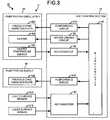
- the unit control section 18 is equipped with a microcomputer 56, the pump driving circuits 57A and 57B, a heater driving circuit 58 and AD converters 59 and 60.
- the unit control section 18 is mounted, for example, on the outer surface of the ink circulation device 17 through a screw.
- a section for controlling the pressure sensor 32 and a section for controlling the actuator of the inkjet head 16 in the unit control section 18 are not recorded in Fig. 3 , and the description thereof is omitted.
- the unit control section 18 is dedicated to the ink circulation device 17, and the control section for controlling the inkjet head 16 may be arranged separated from the unit control section 18.
- the microcomputer 56 includes an arithmetic circuit and a memory (not shown).
- the memory stores a control program of the microcomputer 56 and Curie temperature of the piezoelectric vibration plate 42A.
- the Curie temperature of the piezoelectric vibration plate 42A is, for example, 200 degrees centigrade ⁇ 300 degrees centigrade.
- the pump driving circuits 57A and 57B generate a predetermined alternating voltage.
- the pump driving circuit 57A is connected with the piezoelectric vibration plate 42A to control the piezoelectric vibration plate 42A.
- the pump driving circuit 57B is connected with the piezoelectric vibration plate 42B to control the piezoelectric vibration plate 42B.
- the heater driving circuit 58 generates, for example, various voltage waveforms the sizes of which are different and applies the voltage to the heater 44A.
- the heater driving circuit 58 controls the heater 44A.
- the AD converter 59 converts a voltage signal to a digital waveform through an analog waveform sent from the heater temperature sensor 46A to send the digital waveform to the microcomputer 56.
- the AD converter 60 converts a voltage signal to a digital waveform through an analog waveform sent from the liquid surface sensors 31A and 31B to send the digital waveform to the microcomputer 56.
- the microcomputer 56 controls the heater driving circuit 58 based on the detection result of the temperature of the heater 44A sent from the AD converter 59 in such a manner that the temperature detected by the heater temperature sensor 46A is equal to or lower than the half of the Curie temperature of the piezoelectric vibration plate 42A. Through such a control operation, piezoelectric property of the piezoelectric vibration plate 42A cannot be lost.
- the temperature detected by the heater temperature sensor 46A is controlled to be equal to or lower than the half of the Curie temperature of the piezoelectric vibration plate 42A; however, the temperature detected by the heater temperature sensor 46A may be controlled to be lower than the Curie temperature of the piezoelectric vibration plate 42A.
- the microcomputer 56 steadily drives the piezoelectric vibration plate 42A of the pump for ink circulation 48 with the pump driving circuit 57A, and regularly reads the detection result of the temperature which is converted by the AD converter 59 and detected by the heater temperature sensor 46A. Then, the microcomputer 56 controls the heater driving circuit 58 to apply the voltage to the heater 44A in such a manner that the temperature of the heater 44A detected by the heater temperature sensor 46A is equal to or lower than the half of the Curie temperature of the piezoelectric vibration plate 42A.
- the temperature of the heater 44A detected by the heater temperature sensor 46A is controlled to be equal to or lower than the half of the Curie temperature, in other words, equal to or lower than 100 degrees centigrade ⁇ 150 degrees centigrade.
- the temperature detected by the heater temperature sensor 46A is controlled to be 45 degrees centigrade.
- the heater 44A As the heater 44A is laminated on the piezoelectric vibration plate 42A, the heat generated by the heater 44A is easily transmitted to the ink I in the pressure chamber for circulation 25c. Further, the temperature of the heater 44A is equal to or lower than the half of the Curie temperature of the piezoelectric vibration plate 42A so that the collapse of the piezoelectric property of the piezoelectric vibration plate 42A is suppressed. As shown in Fig. 4 , the ink I in the pressure chamber for circulation 25c is absorbed from the flow hole 25a and ejected from the flow hole 25b in a direction indicated by an arrow A1.
- the ink I ejected from the flow hole 25b flows into the ink supply chamber 22 through the communicating path 27 after passing the filter 30 through the ink chamber 26.
- the rubbish or bubble contained in the ink I is trapped by the filter 30.
- the ink I flows into the inkjet head 16 through the ink supply pipe 52.
- the microcomputer 56 properly controls the actuator of the inkjet head 16 to inject the ink I from each nozzle section to carry out printing on the image receiving medium S.
- the ink I in the ink collection chamber 23 is absorbed from the flow hole 25a into the pressure chamber for circulation 25c through the inflow port 29.
- the ink I in the ink circulation device 17 and the inkjet head 16 flows to be circulated.
- the microcomputer 56 drives the piezoelectric vibration plate 42A to apply the voltage to the heater 44A at the time the ink I circulates in the ink circulation device 17 and the inkjet head 16.
- the ink I is wholly heated without being locally heated and the ink I is difficult to be destroyed.
- the destruction of the ink refers to alteration, degradation, separation or aggregation of the ink.
- the reduction of the ink I is detected by, for example, the liquid surface sensors 31A and 31B, and the detection result is sent to the unit control section 18.
- the microcomputer 56 drives the piezoelectric vibration plate 42B of the pump for ink supply 49 with the pump driving circuit 57B.
- the ink I in the pressure chamber for supply 24c is absorbed from the flow hole 24a and ejected from the flow hole 24b in a direction indicated by an arrow A2.
- the ink I is absorbed from the flow hole 24a to be supplied to the inside of the pressure chamber for supply 24c from the ink cartridge via the connection tube and the replenishing path 28.
- the ink I ejected from the flow hole 24b flows into the ink supply chamber 22 through the communicating path 27 after passing the filter 30 through the ink chamber 26. Then, the ink I merges with the ink I indicated by the arrow A1.
- the ink I is supplied from the external ink cartridge to the inside of the ink circulation device 17.
- the amount of the ink I in the inkjet unit 15 is equal to or greater than a certain amount, that the amount of the ink I is equal to or greater than a certain amount is detected by the liquid surface sensors 31A and 31B and then is sent to the unit control section 18.
- the microcomputer 56 stops driving the piezoelectric vibration plate 42B of the pump for ink supply 49 with the pump driving circuit 57B.
- Fig. 6 illustrates changes of the temperatures indicated by the vertical axis detected by the temperature sensor in the inkjet head with respect to time indicated by the horizontal axis in the inkjet units of the embodiment and the comparative embodiment.
- the inkjet unit of the comparative embodiment is not equipped with the heater temperature sensor 46A, and arranges the heater 44A on the outer surface of the lower side of the casing 21 not in the pump for ink circulation 48.
- a thin pipe through which the ink I flows is arranged inside the inkjet head 16.
- a temperature sensor is arranged on the outer surface of the pipe. The heaters of the inkjet units of the embodiment and the comparative embodiment are applied with the same heat generation amount per unit time to compare the temperatures detected by the temperature sensors of the inkjet heads 16.
- the experimental result of the embodiment is indicated by a curve L1 which is a solid line.
- the experimental result of the comparative embodiment is indicated by a curve L2 which is a dotted line.
- the actuator unit for circulation 36A on which the heater is mounted is relatively thin, the actuator unit for circulation 36A is heated at a position very close to the ink I, and the loss due to heat dissipation is small, it can be found that the temperature detected by the temperature sensor easily rises as the time elapses.
- the ink circulation device 17 and the printer 1 of the present embodiment as the heater 44A is laminated on the piezoelectric vibration plate 42A, the heat generated by the heater 44A is easily transmitted to the ink I in the pressure chamber for circulation 25c.
- the piezoelectric vibration plate 42A When the piezoelectric vibration plate 42A is driven and the ink I flows, as the voltage is applied to the heater 44A, the ink I can be difficultly destroyed without being locally heated.
- the voltage is applied to the heater 44A in such a manner that the temperature detected by the heater temperature sensor 46A is equal to or lower than the half of the Curie temperature of the piezoelectric vibration plate 42A so that the collapse of the piezoelectric property of the piezoelectric vibration plate 42A can be suppressed.
- the ink I can be efficiently heated by the heater 44A without destroying the ink I in the inkjet unit 15.
- the heater 44A may be arranged between the liquid contact sheet 41A and the piezoelectric vibration plate 42A. In other words, the heater 44A may be arranged at a position closer to the ink I which is desired to be heated by the heater 44A. Through such a configuration, the heat generated by the heater 44A is easier to be transmitted to the ink I.
- the pump for ink circulation 48 is equipped with the heater 44A; however, it is not limited to that.
- the pump for ink supply 49 may also be equipped with a heater in addition to the pump for ink circulation 48.
- the actuator unit for circulation 36A may not include the insulating sheets 43A and 45A.
- the heat generated by the heater 44A can be easily transmitted to the ink I.
- a figure or a parameter from one range may be combined with another figure or a parameter from a different range for the same characteristic to generate a numerical range.
Landscapes
- Engineering & Computer Science (AREA)
- Quality & Reliability (AREA)
- Ink Jet (AREA)
- Particle Formation And Scattering Control In Inkjet Printers (AREA)
Abstract
Description
- Embodiments described herein relate generally to an ink circulation device and a printer.
- There is known an ink circulation device for a circulation-type inkjet head corresponding to various kinds of ink, such as solvent ink, oil-based ink or water-based ink. In order to eject a proper liquid drop amount of the ink from the inkjet head, in some cases, the ink is heated to adjust the viscosity thereof.
- The shape forming the appearance of the ink circulation device is constituted by a casing. If the ink inside the ink circulation device is heated with a heater mounted on the outer surface of the casing, as the casing is relatively thick, it is difficult to transmit heat generated by the heater to the ink, and there is a problem that the ink cannot be heated to a desired temperature.
- To solve such problems, there is provided an ink circulation device, comprising:
- a pressure chamber comprising at least two flow holes through which ink flows;
- a piezoelectric vibration plate constituting a part of a wall of the pressure chamber and configured to be driven to increase or decrease an inner volume of the pressure chamber;
- a valve for opening and closing at least one of the two flow holes;
- a heater affixed on the piezoelectric vibration plate; and
- a connection section connecting the pressure chamber to an inkjet head.
- Preferably, when the piezoelectric vibration plate is driven and the ink flows, a voltage is applied to the heater.
- Preferably still, the ink circulation device further comprises:
- a temperature sensor configured to detect a temperature of the heater, wherein
- a voltage is applied to the heater so that the temperature detected by the temperature sensor is smaller than a Curie temperature of the piezoelectric vibration plate.
- Preferably yet, the ink circulation device further comprises a pump for ink circulation.
- The invention also relates to a printer, comprising:
- a conveyance section configured to convey an image receiving medium printed with ink to an inkjet head; and
- the ink circulation device as defined above.
- The invention further relates to an ink circulation method within a printer, comprising:
- driving a piezoelectric vibration plate constituting a part of a wall of a pressure chamber to increase or decrease an inner volume of the pressure chamber and thereby circulating ink therein;
- opening and closing at least one of two flow holes in the pressure chamber; and
- heating the piezoelectric vibration plate.
- Preferably, the method further comprises applying voltage to a heater while driving the piezoelectric vibration plate.
- Preferably still, the method further comprises:
- applying voltage to a heater;
- detecting a temperature of a heater; and
- controlling the applied voltage so that the temperature detected is smaller than a Curie temperature of the piezoelectric vibration plate.
- Preferably yet, the method further comprises:
- detecting a temperature of a heater; and
- controlling the applied voltage so that the temperature detected is smaller than a Curie temperature of the piezoelectric vibration plate.
- Suitably, the method further comprises using a pump for ink circulation.
- Suitably still, the Curie temperature of the piezoelectric vibration plate is 200 to 300 degrees centigrade.
- Suitably yet, the temperature of the heater is one half the Curie temperature or less.
- Typically, the Curie temperature of the piezoelectric vibration plate is 200 to 300 degrees centigrade.
- Typically still, the temperature of the heater is one half the Curie temperature or less.
- Typically yet, the Curie temperature of the piezoelectric vibration plate is 200 to 300 degrees centigrade and the temperature of the heater is one half the Curie temperature or less.
- The above and other objects, features and advantages of the present invention will be made apparent from the following description of the preferred embodiments, given as non-limiting examples, with reference to the accompanying drawings, in which:
-
Fig. 1 is a front view schematically illustrating a printer according to an embodiment; -
Fig. 2 is a perspective view of an inkjet unit of the printer according to the embodiment; -
Fig. 3 is a block diagram of the inkjet unit according to the embodiment; -
Fig. 4 is a cross-sectional view of an ink circulation device according to the embodiment; -
Fig. 5 is a perspective view illustrating a disassembled actuator unit for circulation of the ink circulation device according to the embodiment; and -
Fig. 6 is a diagram illustrating change of a temperature detected by a temperature sensor inside an inkjet head with respect to time in the ink circulation device according to an embodiment and a comparative embodiment. - In accordance with an embodiment, an ink circulation device comprises a pressure chamber, a piezoelectric vibration plate, a valve, a heater and a connection section. The pressure chamber includes at least two flow holes through which ink flows. The piezoelectric vibration plate constitutes a part of a wall of the pressure chamber and is driven to increase or decrease an inner volume of the pressure chamber. The valve opens and closes at least one of the two flow holes. The heater is laminated on the piezoelectric vibration plate. The connection section connects the pressure chamber to an inkjet head.
- In accordance with another embodiment, an ink circulation method within a printer involves driving a piezoelectric vibration plate constituting a part of a wall of a pressure chamber to increase or decrease an inner volume of the pressure chamber and thereby circulating ink therein; opening and closing at least one of two flow holes in the pressure chamber; and heating the piezoelectric vibration plate.
- Hereinafter, an embodiment relating to the ink circulation device and a printer is described with reference to the accompany drawings.
- As shown in
Fig. 1 , aprinter 1 according to the present embodiment is equipped with a feeding table 3, acarriage 4, and amaintenance unit 5 inside a housing 2. - The feeding table 3 is slidably held by a guide rail for feeding 6 arranged inside the housing 2. The guide rail for
feeding 6 linearly extends in a substantially horizontal direction. The feeding table 3 is moved in a direction along the guide rail for feeding 6 by a motor (not shown). A negativepressure generation device 7 for absorbing a sheet-like image receiving medium S such as a sheet to fix the image receiving medium S on the feeding table 3 is arranged in the feeding table 3. The feeding table 3, the guide rail forfeeding 6, the motor and the negativepressure generation device 7 constitute aconveyance section 8 for conveying the image receiving medium S to aninkjet head 16 described later. - Further, the image receiving medium S is not limited to a paper, and it may be a film made of resin or metal or a plate made of wood.
- The
carriage 4 is sidably held by a guide rail for scanning (not shown) arranged inside the housing 2. The guide rail for scanning linearly extends in a substantially horizontal direction orthogonal to the guide rail forfeeding 6. Thecarriage 4 is moved in a direction along the guide rail for scanning through aconveyance belt 9 driven by a motor (not shown). A plurality ofinkjet units 15 arranged along a scanning direction of thecarriage 4 is loaded in thecarriage 4. - As shown in
Fig. 1 to Fig. 3 , theinkjet unit 15 is equipped with aninkjet head 16 for injecting the ink I onto the image receiving medium S, anink circulation device 17 of the present embodiment connected with theinkjet head 16 at the upper side of theinkjet head 16 and a unit control section (control section) 18 for controlling theinkjet head 16 and theink circulation device 17. - The
inkjet unit 15 the number of which corresponds to the category of the ink I injected onto the image receiving medium S is loaded in thecarriage 4. The ink I injected from eachinkjet unit 15 may include transparent glossiness ink or special ink which develops color when irradiated with an infrared ray or an ultraviolet ray in addition to the ink having various colors such as cyan, magenta, yellow, black, white and the like. - An ink cartridge (not shown) is connected with the
ink circulation device 17 of eachinkjet unit 15. These ink cartridges are arranged inside the housing 2. Theink circulation device 17 of eachinkjet unit 15 and the ink cartridge are connected with each other through a flexible connection tube (not shown). A plurality of theinkjet units 15 is aggregately arranged above thecarriage 4 and moves along the guide rail for scanning together with thecarriage 4. - The
maintenance unit 5 covers the injection section of theinkjet head 16 for injecting the ink I to prevent evaporation of the ink I at the time a plurality of theinkjet units 15 and thecarriage 4 return to a standby position at which the ink I is not injected from theinkjet head 16. Themaintenance unit 5 appropriately cleans the contact portion of theinkjet head 16 with the image receiving medium S at the time a plurality of theinkjet units 15 returns to the standby position. - A
main control section 10 is connected with the motor, the negativepressure generation device 7, themaintenance unit 5 and eachinkjet unit 15 to control them. - The
inkjet head 16 of eachinkjet unit 15 is equipped with a plurality of nozzle sections (not shown) for injecting the ink I onto the image receiving medium S and actuators (not shown) arranged to face each nozzle section. The actuator is composed of, for example, a piezoelectric vibration plate using piezoelectric ceramic. If a signal is input to the actuator, the actuator increases the pressure of the ink I so that the ink I is injected from each nozzle section. With the injected ink I, the image receiving medium S is printed. - As shown in
Fig. 2 andFig. 4 , theink circulation device 17 of eachinkjet unit 15 is equipped with acasing 21, an actuator unit forcirculation 36A and an actuator unit forsupply 36B which are mounted in thecasing 21,valve bodies connection section 40. Thecasing 21 is formed by, for example, carrying out die casting on aluminum. In thecasing 21, anink supply chamber 22, anink collection chamber 23, a supplypump housing chamber 24, a circulationpump housing chamber 25, anink chamber 26, a communicatingpath 27, a replenishingpath 28, and aninflow port 29 serving as internal spaces are formed. - As shown in
Fig. 3 andFig. 4 , a well-knownliquid surface sensor 31B for detecting a liquid surface of the ink I in theink supply chamber 22 is mounted in theink supply chamber 22. A well-knownliquid surface sensor 31A for detecting a liquid surface of the ink I in theink collection chamber 23 is mounted in theink collection chamber 23. Theliquid surface sensors unit control section 18 to send detection results of the liquid surface of the ink I to theunit control section 18. Though not shown, the upper part of the liquid surface of the ink I in theink supply chamber 22 and the upper part of the liquid surface of the ink I in theink collection chamber 23 respectively form air chambers. Apressure sensor 32 and apressure adjustment section 33 shown inFig. 2 are mounted in thecasing 21. Thepressure sensor 32 communicates with each forgoing air chamber to detect the pressure of the twoink chambers pressure adjustment section 33 adjusts the pressure of the inside of thecasing 21 so as to properly keep surface pressure of each nozzle section of theinkjet head 16 based on the detection result of thepressure sensor 32. - As shown in
Fig. 4 , theink supply chamber 22 communicates with the communicatingpath 27. An end of the replenishingpath 28 forms a pipe line of a replenishingport 28a arranged at the outer surface of thecasing 21 and opens to the outside of thecasing 21. The replenishingport 28a is connected with the foregoing ink cartridge via a connection tube. The replenishingpath 28 communicates with the supplypump housing chamber 24 via aflow hole 24a penetrating a wall which partitions the replenishingpath 28 and the supplypump housing chamber 24. In the wall, thevalve body 38A serving as a well-known check valve is mounted. Thevalve body 38A opens and closes theflow hole 24a to allow the flow of the ink I from the replenishingpath 28 to the supplypump housing chamber 24 through theflow hole 24a and regulate the flow of the ink I from the supplypump housing chamber 24 to the replenishingpath 28. The supplypump housing chamber 24 communicates with theink chamber 26 via aflow hole 24b penetrating a wall which partitions theink chamber 26 and the supplypump housing chamber 24. In the wall, thevalve body 38B is mounted. Thevalve body 38B opens and closes theflow hole 24b to allow the flow of the ink I from the supplypump housing chamber 24 to theink chamber 26 through theflow hole 24b and regulate the flow of the ink I from theink chamber 26 to the supplypump housing chamber 24. - The
ink chamber 26 communicates with the communicatingpath 27 via afilter 30. Theink collection chamber 23 communicates with theinflow port 29. Theinflow port 29 communicates with the circulationpump housing chamber 25 via aflow hole 25a penetrating a wall which partitions theinflow port 29 and the circulationpump housing chamber 25. In the wall, thevalve body 39A is mounted. Thevalve body 39A opens and closes theflow hole 25a to allow the flow of the ink I from theinflow port 29 to the circulationpump housing chamber 25 through theflow hole 25a and regulate the flow of the ink I from the circulationpump housing chamber 25 to theinflow port 29. The circulationpump housing chamber 25 communicates with theink chamber 26 via aflow hole 25b penetrating a wall which partitions theink chamber 26 and the circulationpump housing chamber 25. In the wall, thevalve body 39B is mounted. Thevalve body 39B opens and closes theflow hole 25b to allow the flow of the ink I from the circulationpump housing chamber 25 to theink chamber 26 through theflow hole 25b and regulate the flow of the ink I from theink chamber 26 to the circulationpump housing chamber 25. - In the present embodiment, the components of the actuator unit for
circulation 36A are the same as those of the actuator unit forsupply 36B except that the actuator unit forsupply 36B is not equipped with aheater 44A and aheater temperature sensor 46A described later. Thus, the component of the actuator unit forcirculation 36A is indicated by adding a capital letter "A" to the number, and the component of the actuator unit forsupply 36B corresponding to that of the actuator unit forcirculation 36A is indicated by adding a capital letter "B" to the same number as the actuator unit forcirculation 36A. In this way, the repeated description thereof is omitted. For example, apiezoelectric vibration plate 42A and apiezoelectric vibration plate 42B shown inFig. 3 are the same components. - As shown in
Fig. 5 , the actuator unit forcirculation 36A is formed into a laminated structure by laminating aliquid contact sheet 41A, thepiezoelectric vibration plate 42A, an insulatingsheet 43A, theheater 44A, an insulatingsheet 45A and a heater temperature sensor (temperature sensor) 46A in order in a mutually attached manner. - The
liquid contact sheet 41A is made of resin which contacts with the ink I in a pressure chamber forcirculation 25c described later. PI (polyimide) which is difficult to generate chemical change due to the solvent of the ink is used as the material forming theliquid contact sheet 41A. In the embodiment, theliquid contact sheet 41A, thepiezoelectric vibration plate 42A and the insulatingsheets - The
piezoelectric vibration plate 42A is a unimorph type piezoelectric vibration plate composed of a metal plate 42aA and a piezoelectric ceramic 42bA. The material forming the metal plate 42aA is, for example, brass. The material forming the piezoelectric ceramic 42bA is, for example, PZT (lead zirconate titanate). The piezoelectric ceramic 42bA is subjected to Ni/Au-plated electrode on upper and lower surfaces thereof and has a piezoelectric property by a polarization processing. An end of a lead wire for vibration plate 42cA is respectively connected with the metal plate 42aA and the piezoelectric ceramic 42bA through a solder portion 42dA. The lead wire for vibration plate 42cA is a cable for applying AC voltage generated by apump driving circuit 57A described later of theunit control section 18 to thepiezoelectric vibration plate 42A. - The
heater 44A is configured by respectively connecting a lead wire for heater 44bA with both ends of a heater main body 44aA which is formed into a bellows shape. The heater main body 44aA is a resistor, formed by a heating wire such as stainless steel, nichrome wire and the like, of which the value of the electrical resistance is several Ω (ohms) to several thousand Ω. In the embodiment, the heater main body 44aA is formed into a bellows shape; however, the shape of the heater main body 44aA is not particularly limited as long as it is a shape which can increase the length of the heater main body 44aA arranged in a certain area. The heater main body 44aA can be formed into a spiral shape or the like other than the bellows shape. The heater main body 44aA generates heat if a voltage from theunit control section 18 is applied. The generated heat is used to heat the ink I in the pressure chamber forcirculation 25c described later via the insulatingsheet 43A, thepiezoelectric vibration plate 42A and theliquid contact sheet 41A. - It is preferable that the lead wire for heater 44bA of the
heater 44A and the lead wire for vibration plate 42cA of thepiezoelectric vibration plate 42A are arranged in different directions of the circumferential direction thepiezoelectric vibration plate 42A. With such a configuration, it can be suppressed that theheater 44A contacts with the solder portion 42dA. In the present embodiment, theheater 44A is arranged between the insulatingsheet 43A and the insulatingsheet 45A. - The insulating
sheets heater 44A by sandwiching theheater 44A therebetween. The insulatingsheets sheets circulation 36A can be suppressed. - A thermistor can be suitably used in the
heater temperature sensor 46A. Theheater temperature sensor 46A is affixed or laminated on thepiezoelectric vibration plate 42A across the insulatingsheets heater 44A. Theheater temperature sensor 46A is connected to theunit control section 18 to transmit the detected temperature of theheater 44A to theunit control section 18. In order to mutually bond theliquid contact sheet 41A with thepiezoelectric vibration plate 42A, an epoxy-based or silicone-based adhesive can be used or an adhesive tape can be used. - The actuator unit for
circulation 36A with such a configuration is formed into a thin plate shape of which the thickness of the whole is 500~1000 µm (micrometers). Thus, the heat generated by theheater 44A can be transmitted to the ink I with a little loss. The thickness of the actuator unit forcirculation 36A is sufficiently thinner than that of the wall of thecasing 21. - As shown in
Fig. 4 , the actuator unit forcirculation 36A is mounted in such a manner that the actuator unit forcirculation 36A can be moved at both sides of the thickness direction of the actuator unit forcirculation 36A in the circulationpump housing chamber 25. The space of the circulationpump housing chamber 25 at the flow holes 25a and 25b side with respect to the actuator unit forcirculation 36A, the wall of thecasing 21 surrounding the space and the actuator unit forcirculation 36A constitute a pressure chamber for circulation (pressure chamber) 25c. - In other words, two
flow holes circulation 25c. Thepiezoelectric vibration plate 42A of the actuator unit forcirculation 36A constitutes a part of the wall of the pressure chamber forcirculation 25c. A pump forink circulation 48 for circulating the ink I in theink circulation device 17 and theinkjet head 16 and including the pressure chamber forcirculation 25c and thevalve bodies piezoelectric vibration plate 42A is driven to move the actuator unit forcirculation 36A in the thickness direction thereof to increase or decrease the volume of the inside of the pressure chamber forcirculation 25c. - Similarly, the actuator unit for
supply 36B is mounted in such a manner that the actuator unit forsupply 36B can be moved at both sides of the thickness direction of the actuator unit forsupply 36B in the supplypump housing chamber 24. The space of the supplypump housing chamber 24 at the flow holes 24a and 24b side with respect to the actuator unit forsupply 36B, the wall of thecasing 21 surrounding the space and the actuator unit forsupply 36B constitute a pressure chamber forsupply 24c. - In other words, two
flow holes supply 24c. Thepiezoelectric vibration plate 42B of the actuator unit forsupply 36B constitutes a part of the wall of the pressure chamber forsupply 24c. A pump forink supply 49 for supplying the ink I to theink circulation device 17 from the outside is constituted by the pressure chamber forsupply 24c and thevalve bodies piezoelectric vibration plate 42B is driven to move the actuator unit forsupply 36B in the thickness direction thereof to increase or decrease the volume of the inside of the pressure chamber forsupply 24c. - Further, two
flow holes circulation 25c; however, the number of the flow holes formed in the pressure chamber forcirculation 25c is not particularly limited, and may be three or more, which is the same as the pressure chamber forsupply 24c. - The
inkjet unit 15 may be not equipped with thevalve bodies - As shown in
Fig. 2 , theconnection section 40 includes anink supply pipe 52 and anink return pipe 53. One end of theink supply pipe 52 communicates with theink supply chamber 22 of thecasing 21, and the other end of theink supply pipe 52 communicates with each nozzle section of theinkjet head 16. - On the other hand, one end of the
ink return pipe 53 communicates with each nozzle section of theinkjet head 16, and the other end of theink return pipe 53 communicates with theink collection chamber 23 of thecasing 21. Theink return pipe 53 connects the pressure chamber forcirculation 25c to theinkjet head 16 via theinflow port 29 and theink collection chamber 23. - As shown in
Fig. 3 , theunit control section 18 is equipped with amicrocomputer 56, thepump driving circuits heater driving circuit 58 andAD converters unit control section 18 is mounted, for example, on the outer surface of theink circulation device 17 through a screw. - A section for controlling the
pressure sensor 32 and a section for controlling the actuator of theinkjet head 16 in theunit control section 18 are not recorded inFig. 3 , and the description thereof is omitted. Theunit control section 18 is dedicated to theink circulation device 17, and the control section for controlling theinkjet head 16 may be arranged separated from theunit control section 18. - The
microcomputer 56 includes an arithmetic circuit and a memory (not shown). The memory stores a control program of themicrocomputer 56 and Curie temperature of thepiezoelectric vibration plate 42A. The Curie temperature of thepiezoelectric vibration plate 42A is, for example, 200 degrees centigrade~300 degrees centigrade. Thepump driving circuits pump driving circuit 57A is connected with thepiezoelectric vibration plate 42A to control thepiezoelectric vibration plate 42A. Thepump driving circuit 57B is connected with thepiezoelectric vibration plate 42B to control thepiezoelectric vibration plate 42B. - The
heater driving circuit 58 generates, for example, various voltage waveforms the sizes of which are different and applies the voltage to theheater 44A. Theheater driving circuit 58 controls theheater 44A. TheAD converter 59 converts a voltage signal to a digital waveform through an analog waveform sent from theheater temperature sensor 46A to send the digital waveform to themicrocomputer 56. TheAD converter 60 converts a voltage signal to a digital waveform through an analog waveform sent from theliquid surface sensors microcomputer 56. Themicrocomputer 56 controls theheater driving circuit 58 based on the detection result of the temperature of theheater 44A sent from theAD converter 59 in such a manner that the temperature detected by theheater temperature sensor 46A is equal to or lower than the half of the Curie temperature of thepiezoelectric vibration plate 42A. Through such a control operation, piezoelectric property of thepiezoelectric vibration plate 42A cannot be lost. - In the present embodiment, the temperature detected by the
heater temperature sensor 46A is controlled to be equal to or lower than the half of the Curie temperature of thepiezoelectric vibration plate 42A; however, the temperature detected by theheater temperature sensor 46A may be controlled to be lower than the Curie temperature of thepiezoelectric vibration plate 42A. - Next, the function of the
inkjet unit 15 of theprinter 1 with the foregoing configuration is described. - The
microcomputer 56 steadily drives thepiezoelectric vibration plate 42A of the pump forink circulation 48 with thepump driving circuit 57A, and regularly reads the detection result of the temperature which is converted by theAD converter 59 and detected by theheater temperature sensor 46A. Then, themicrocomputer 56 controls theheater driving circuit 58 to apply the voltage to theheater 44A in such a manner that the temperature of theheater 44A detected by theheater temperature sensor 46A is equal to or lower than the half of the Curie temperature of thepiezoelectric vibration plate 42A. - In a case in which the Curie temperature of the
piezoelectric vibration plate 42A is 200 degrees centigrade~300 degrees centigrade, the temperature of theheater 44A detected by theheater temperature sensor 46A is controlled to be equal to or lower than the half of the Curie temperature, in other words, equal to or lower than 100 degrees centigrade~150 degrees centigrade. For example, the temperature detected by theheater temperature sensor 46A is controlled to be 45 degrees centigrade. - As the
heater 44A is laminated on thepiezoelectric vibration plate 42A, the heat generated by theheater 44A is easily transmitted to the ink I in the pressure chamber forcirculation 25c. Further, the temperature of theheater 44A is equal to or lower than the half of the Curie temperature of thepiezoelectric vibration plate 42A so that the collapse of the piezoelectric property of thepiezoelectric vibration plate 42A is suppressed. As shown inFig. 4 , the ink I in the pressure chamber forcirculation 25c is absorbed from theflow hole 25a and ejected from theflow hole 25b in a direction indicated by an arrow A1. - The ink I ejected from the
flow hole 25b flows into theink supply chamber 22 through the communicatingpath 27 after passing thefilter 30 through theink chamber 26. The rubbish or bubble contained in the ink I is trapped by thefilter 30. - If the pressure of the ink I in the
ink supply chamber 22 is increased, the ink I flows into theinkjet head 16 through theink supply pipe 52. Themicrocomputer 56 properly controls the actuator of theinkjet head 16 to inject the ink I from each nozzle section to carry out printing on the image receiving medium S. - The ink I that returns from the
inkjet head 16 through theink return pipe 53 without being injected from each nozzle section flows into theink collection chamber 23. The ink I in theink collection chamber 23 is absorbed from theflow hole 25a into the pressure chamber forcirculation 25c through theinflow port 29. - In this way, through the pump for
ink circulation 48, the ink I in theink circulation device 17 and theinkjet head 16 flows to be circulated. Themicrocomputer 56 drives thepiezoelectric vibration plate 42A to apply the voltage to theheater 44A at the time the ink I circulates in theink circulation device 17 and theinkjet head 16. Thus, the ink I is wholly heated without being locally heated and the ink I is difficult to be destroyed. The destruction of the ink refers to alteration, degradation, separation or aggregation of the ink. - On the other hand, if the ink I in the
inkjet unit 15 is reduced, the reduction of the ink I is detected by, for example, theliquid surface sensors unit control section 18. - The
microcomputer 56 drives thepiezoelectric vibration plate 42B of the pump forink supply 49 with thepump driving circuit 57B. The ink I in the pressure chamber forsupply 24c is absorbed from theflow hole 24a and ejected from theflow hole 24b in a direction indicated by an arrow A2. - The ink I is absorbed from the
flow hole 24a to be supplied to the inside of the pressure chamber forsupply 24c from the ink cartridge via the connection tube and the replenishingpath 28. - On the other hand, the ink I ejected from the
flow hole 24b flows into theink supply chamber 22 through the communicatingpath 27 after passing thefilter 30 through theink chamber 26. Then, the ink I merges with the ink I indicated by the arrow A1. - In this way, through the pump for
ink supply 49, the ink I is supplied from the external ink cartridge to the inside of theink circulation device 17. - If the amount of the ink I in the
inkjet unit 15 is equal to or greater than a certain amount, that the amount of the ink I is equal to or greater than a certain amount is detected by theliquid surface sensors unit control section 18. - The
microcomputer 56 stops driving thepiezoelectric vibration plate 42B of the pump forink supply 49 with thepump driving circuit 57B. -
Fig. 6 illustrates changes of the temperatures indicated by the vertical axis detected by the temperature sensor in the inkjet head with respect to time indicated by the horizontal axis in the inkjet units of the embodiment and the comparative embodiment. Compared with the inkjet unit of the embodiment, the inkjet unit of the comparative embodiment is not equipped with theheater temperature sensor 46A, and arranges theheater 44A on the outer surface of the lower side of thecasing 21 not in the pump forink circulation 48. - Though not shown, a thin pipe through which the ink I flows is arranged inside the
inkjet head 16. A temperature sensor is arranged on the outer surface of the pipe. The heaters of the inkjet units of the embodiment and the comparative embodiment are applied with the same heat generation amount per unit time to compare the temperatures detected by the temperature sensors of the inkjet heads 16. - The experimental result of the embodiment is indicated by a curve L1 which is a solid line. The experimental result of the comparative embodiment is indicated by a curve L2 which is a dotted line. In the inkjet unit of the comparative embodiment, if the thickness of the wall of the
casing 21 on which the heater is mounted is relatively large and the heat is difficult to be transmitted, as the loss due to heat dissipation is large, it can be found that the temperature detected by the temperature sensor difficultly rises as the time elapses. - On the contrary, in the inkjet unit of the embodiment, as the thickness of the actuator unit for
circulation 36A on which the heater is mounted is relatively thin, the actuator unit forcirculation 36A is heated at a position very close to the ink I, and the loss due to heat dissipation is small, it can be found that the temperature detected by the temperature sensor easily rises as the time elapses. - As stated above, according to the
ink circulation device 17 and theprinter 1 of the present embodiment, as theheater 44A is laminated on thepiezoelectric vibration plate 42A, the heat generated by theheater 44A is easily transmitted to the ink I in the pressure chamber forcirculation 25c. - When the
piezoelectric vibration plate 42A is driven and the ink I flows, as the voltage is applied to theheater 44A, the ink I can be difficultly destroyed without being locally heated. - The voltage is applied to the
heater 44A in such a manner that the temperature detected by theheater temperature sensor 46A is equal to or lower than the half of the Curie temperature of thepiezoelectric vibration plate 42A so that the collapse of the piezoelectric property of thepiezoelectric vibration plate 42A can be suppressed. - As the pump for
ink circulation 48 including theheater 44A steadily feeds the ink I, the ink I can be efficiently heated by theheater 44A without destroying the ink I in theinkjet unit 15. - Further, in the present embedment, the
heater 44A may be arranged between theliquid contact sheet 41A and thepiezoelectric vibration plate 42A. In other words, theheater 44A may be arranged at a position closer to the ink I which is desired to be heated by theheater 44A. Through such a configuration, the heat generated by theheater 44A is easier to be transmitted to the ink I. - The pump for
ink circulation 48 is equipped with theheater 44A; however, it is not limited to that. The pump forink supply 49 may also be equipped with a heater in addition to the pump forink circulation 48. - In a case in which the
heater 44A is coated by an insulating material, the actuator unit forcirculation 36A may not include the insulatingsheets - According to at least one embodiment described above, with the
heater 44A laminated on thepiezoelectric vibration plate 42A, the heat generated by theheater 44A can be easily transmitted to the ink I. - With respect to any figure or numerical range for a given characteristic, a figure or a parameter from one range may be combined with another figure or a parameter from a different range for the same characteristic to generate a numerical range.
- Other than in the operating examples, or where otherwise indicated, all numbers, values and/or expressions referring to conditions, etc., used in the specification and claims are to be understood as modified in all instances by the term "about."
- While certain embodiments have been described, these embodiments have been presented by way of example only, and are not intended to limit the scope of the invention. Indeed, the novel embodiments described herein may be embodied in a variety of other forms; furthermore, various omissions, substitutions and changes in the form of the embodiments described herein may be made without departing from the framework of the invention. The accompanying claims and their equivalents are intended to cover such forms or modifications as would fall within the scope and framework of the invention.
Claims (15)
- An ink circulation device, comprising:a pressure chamber comprising at least two flow holes through which ink flows;a piezoelectric vibration plate constituting a part of a wall of the pressure chamber and configured to be driven to increase or decrease an inner volume of the pressure chamber;a valve for opening and closing at least one of the two flow holes;a heater affixed on the piezoelectric vibration plate; anda connection section connecting the pressure chamber to an inkjet head.
- The ink circulation device according to claim 1, wherein
when the piezoelectric vibration plate is driven and the ink flows, a voltage is applied to the heater. - The ink circulation device according to claim 1 or 2, further comprising a temperature sensor configured to detect a temperature of the heater,
wherein
a voltage is applied to the heater so that the temperature detected by the temperature sensor is smaller than a Curie temperature of the piezoelectric vibration plate. - The ink circulation device according to according to claims 1 to 3, further comprising
a pump for ink circulation. - A printer, comprising:a conveyance section configured to convey an image receiving medium printed with ink to an inkjet head; andan ink circulation device according to any one of claims 1 to 4.
- An ink circulation method within a printer, comprising:driving a piezoelectric vibration plate constituting a part of a wall of a pressure chamber to increase or decrease an inner volume of the pressure chamber and thereby circulating ink therein;opening and closing at least one of two flow holes in the pressure chamber; andheating the piezoelectric vibration plate.
- The method according to claim 6, further comprising
applying voltage to a heater while driving the piezoelectric vibration plate. - The method according to claim 6, further comprising
applying voltage to a heater;
detecting a temperature of a heater; and
controlling the applied voltage so that the temperature detected is smaller than a Curie temperature of the piezoelectric vibration plate. - The method according to claim 7, further comprising
detecting a temperature of a heater; and
controlling the applied voltage so that the temperature detected is smaller than a Curie temperature of the piezoelectric vibration plate. - The method according to any one of claims 6 to 9, further comprising using a pump for ink circulation.
- The method according to claim 8, wherein the Curie temperature of the piezoelectric vibration plate is 200 to 300 degrees centigrade.
- The method according to claim 11, wherein the temperature of the heater is one half the Curie temperature or less.
- The method according to claim 9, wherein the Curie temperature of the piezoelectric vibration plate is 200 to 300 degrees centigrade.
- The method according to claim 13, wherein the temperature of the heater is one half the Curie temperature or less.
- The method according to claim 8, wherein the Curie temperature of the piezoelectric vibration plate is 200 to 300 degrees centigrade and the temperature of the heater is one half the Curie temperature or less.
Applications Claiming Priority (1)
| Application Number | Priority Date | Filing Date | Title |
|---|---|---|---|
| JP2016014819A JP6695154B2 (en) | 2016-01-28 | 2016-01-28 | Ink circulation device and printer |
Publications (1)
| Publication Number | Publication Date |
|---|---|
| EP3199355A1 true EP3199355A1 (en) | 2017-08-02 |
Family
ID=56939965
Family Applications (1)
| Application Number | Title | Priority Date | Filing Date |
|---|---|---|---|
| EP16189293.0A Withdrawn EP3199355A1 (en) | 2016-01-28 | 2016-09-16 | Ink circulation device and printer |
Country Status (4)
| Country | Link |
|---|---|
| US (1) | US9878535B2 (en) |
| EP (1) | EP3199355A1 (en) |
| JP (1) | JP6695154B2 (en) |
| CN (1) | CN107009753B (en) |
Families Citing this family (8)
| Publication number | Priority date | Publication date | Assignee | Title |
|---|---|---|---|---|
| JP6766634B2 (en) * | 2016-12-21 | 2020-10-14 | セイコーエプソン株式会社 | Liquid discharge device |
| JP7055656B2 (en) * | 2018-02-13 | 2022-04-18 | 東芝テック株式会社 | Liquid discharge head and liquid discharge device |
| JP7118850B2 (en) * | 2018-10-12 | 2022-08-16 | 東芝テック株式会社 | Liquid circulation device and liquid ejection device |
| WO2021008698A1 (en) * | 2019-07-17 | 2021-01-21 | Scrona Ag | Ventilated print head |
| CN114270287B (en) * | 2019-08-30 | 2023-04-11 | 京瓷株式会社 | Circulation device |
| WO2021242255A1 (en) | 2020-05-29 | 2021-12-02 | Hewlett-Packard Development Company, L.P. | Printing fluid circulation |
| JP2023065778A (en) * | 2021-10-28 | 2023-05-15 | 京セラドキュメントソリューションズ株式会社 | Inkjet recording device, and method for controlling inkjet recording device |
| JP7830113B2 (en) * | 2021-12-17 | 2026-03-16 | キヤノン株式会社 | Liquid dispensing head and liquid dispensing device |
Citations (3)
| Publication number | Priority date | Publication date | Assignee | Title |
|---|---|---|---|---|
| US20080030554A1 (en) * | 2006-08-02 | 2008-02-07 | Brother Kogyo Kabushiki Kaisha | Liquid transporting apparatus and ink-jet printer |
| US20150174910A1 (en) * | 2013-12-19 | 2015-06-25 | Toshiba Tec Kabushiki Kaisha | Piezoelectric pump and ink jet apparatus having the same |
| EP2995458A1 (en) * | 2014-09-01 | 2016-03-16 | Toshiba TEC Kabushiki Kaisha | Liquid pump having a piezoelectric member and inkjet apparatus having the same |
Family Cites Families (7)
| Publication number | Priority date | Publication date | Assignee | Title |
|---|---|---|---|---|
| US4607261A (en) * | 1985-04-12 | 1986-08-19 | Eastman Kodak Company | Ink supply cartridge and cooperative ink circulation system of continuous ink jet printer |
| JP2001193656A (en) * | 2000-01-17 | 2001-07-17 | Ckd Corp | Piezo element pump |
| TW561223B (en) * | 2001-04-24 | 2003-11-11 | Matsushita Electric Works Ltd | Pump and its producing method |
| JP4433760B2 (en) * | 2003-10-24 | 2010-03-17 | ソニー株式会社 | Liquid ejection device |
| JP2005178202A (en) * | 2003-12-19 | 2005-07-07 | Fuji Photo Film Co Ltd | Method and device for temperature control of line type inkjet head |
| JP3949135B2 (en) * | 2004-11-17 | 2007-07-25 | シャープ株式会社 | Piezoelectric pump and Stirling refrigerator |
| KR20160122223A (en) * | 2014-02-25 | 2016-10-21 | 캐논 가부시끼가이샤 | Piezoelectric material, piezoelectric element, and electronic apparatus |
-
2016
- 2016-01-28 JP JP2016014819A patent/JP6695154B2/en not_active Expired - Fee Related
- 2016-08-23 US US15/244,239 patent/US9878535B2/en not_active Expired - Fee Related
- 2016-09-16 EP EP16189293.0A patent/EP3199355A1/en not_active Withdrawn
- 2016-12-09 CN CN201611128906.7A patent/CN107009753B/en not_active Expired - Fee Related
Patent Citations (3)
| Publication number | Priority date | Publication date | Assignee | Title |
|---|---|---|---|---|
| US20080030554A1 (en) * | 2006-08-02 | 2008-02-07 | Brother Kogyo Kabushiki Kaisha | Liquid transporting apparatus and ink-jet printer |
| US20150174910A1 (en) * | 2013-12-19 | 2015-06-25 | Toshiba Tec Kabushiki Kaisha | Piezoelectric pump and ink jet apparatus having the same |
| EP2995458A1 (en) * | 2014-09-01 | 2016-03-16 | Toshiba TEC Kabushiki Kaisha | Liquid pump having a piezoelectric member and inkjet apparatus having the same |
Also Published As
| Publication number | Publication date |
|---|---|
| CN107009753A (en) | 2017-08-04 |
| US9878535B2 (en) | 2018-01-30 |
| JP2017132159A (en) | 2017-08-03 |
| JP6695154B2 (en) | 2020-05-20 |
| CN107009753B (en) | 2018-07-20 |
| US20170217164A1 (en) | 2017-08-03 |
Similar Documents
| Publication | Publication Date | Title |
|---|---|---|
| US9878535B2 (en) | Ink circulation device and printer | |
| JP7059640B2 (en) | Liquid discharge head, liquid discharge unit, liquid discharge device | |
| EP2995458B1 (en) | Liquid pump having a piezoelectric member and inkjet apparatus having the same | |
| US9205665B2 (en) | Inkjet apparatus using piezoelectric pump | |
| US8870325B2 (en) | Compensating for capacitance changes in piezoelectric printhead elements | |
| US20120314009A1 (en) | Liquid ejection apparatus | |
| JP6385209B2 (en) | Liquid circulation device, liquid ejection device, and liquid ejection method | |
| JP7259507B2 (en) | liquid ejection head, liquid ejection unit, device for ejecting liquid | |
| US20160059564A1 (en) | Inkjet apparatus that controls a flow rate of liquid circulated therein | |
| US10155381B2 (en) | Liquid discharge head and recording device | |
| US10189255B2 (en) | Liquid discharge head and recording device | |
| US20190193396A1 (en) | Diaphragm pump, liquid circulation module and liquid discharge apparatus | |
| US10987923B2 (en) | Liquid circulation device and liquid discharge device | |
| JP2018154082A (en) | Liquid circulation device, device for discharging liquid | |
| JP2018051768A (en) | Liquid ejecting head, liquid ejecting apparatus | |
| JP2017065248A (en) | Liquid discharge head, liquid discharge unit, and apparatus for discharging liquid | |
| JP6734104B2 (en) | Inkjet printer | |
| WO2017183389A1 (en) | Inkjet head, head module, and inkjet recording device | |
| JP6220798B2 (en) | Inkjet head recording device | |
| CN101152785A (en) | Inkjet recording equipment | |
| JP7517005B2 (en) | LIQUID DISCHARGE HEAD AND DEVICE FOR DISCHARGING LIQUID | |
| JP6377474B2 (en) | Inkjet head and printer | |
| JP7545634B2 (en) | Liquid ejection head, liquid ejection unit, and liquid ejection device | |
| JP7732318B2 (en) | Liquid ejection head and liquid ejection device | |
| JP7494624B2 (en) | LIQUID DISCHARGE HEAD, LIQUID DISCHARGE UNIT, AND DEVICE FOR DISCHARGING LIQUID |
Legal Events
| Date | Code | Title | Description |
|---|---|---|---|
| PUAI | Public reference made under article 153(3) epc to a published international application that has entered the european phase |
Free format text: ORIGINAL CODE: 0009012 |
|
| STAA | Information on the status of an ep patent application or granted ep patent |
Free format text: STATUS: THE APPLICATION HAS BEEN PUBLISHED |
|
| AK | Designated contracting states |
Kind code of ref document: A1 Designated state(s): AL AT BE BG CH CY CZ DE DK EE ES FI FR GB GR HR HU IE IS IT LI LT LU LV MC MK MT NL NO PL PT RO RS SE SI SK SM TR |
|
| AX | Request for extension of the european patent |
Extension state: BA ME |
|
| STAA | Information on the status of an ep patent application or granted ep patent |
Free format text: STATUS: REQUEST FOR EXAMINATION WAS MADE |
|
| 17P | Request for examination filed |
Effective date: 20180202 |
|
| RBV | Designated contracting states (corrected) |
Designated state(s): AL AT BE BG CH CY CZ DE DK EE ES FI FR GB GR HR HU IE IS IT LI LT LU LV MC MK MT NL NO PL PT RO RS SE SI SK SM TR |
|
| STAA | Information on the status of an ep patent application or granted ep patent |
Free format text: STATUS: EXAMINATION IS IN PROGRESS |
|
| 17Q | First examination report despatched |
Effective date: 20190117 |
|
| STAA | Information on the status of an ep patent application or granted ep patent |
Free format text: STATUS: THE APPLICATION IS DEEMED TO BE WITHDRAWN |
|
| 18D | Application deemed to be withdrawn |
Effective date: 20200108 |