EP3199294B1 - System und verfahren zur befestigung/ablösung von werkstücken auf einer werkzeugmaschine mithilfe eines reversiblen haftklebers, und verwendung dieses reversiblen haftklebers - Google Patents
System und verfahren zur befestigung/ablösung von werkstücken auf einer werkzeugmaschine mithilfe eines reversiblen haftklebers, und verwendung dieses reversiblen haftklebers Download PDFInfo
- Publication number
- EP3199294B1 EP3199294B1 EP17382033.3A EP17382033A EP3199294B1 EP 3199294 B1 EP3199294 B1 EP 3199294B1 EP 17382033 A EP17382033 A EP 17382033A EP 3199294 B1 EP3199294 B1 EP 3199294B1
- Authority
- EP
- European Patent Office
- Prior art keywords
- reversible adhesive
- adhesive
- fastening device
- workpiece
- fastening
- Prior art date
- Legal status (The legal status is an assumption and is not a legal conclusion. Google has not performed a legal analysis and makes no representation as to the accuracy of the status listed.)
- Active
Links
Images




Classifications
-
- B—PERFORMING OPERATIONS; TRANSPORTING
- B23—MACHINE TOOLS; METAL-WORKING NOT OTHERWISE PROVIDED FOR
- B23Q—DETAILS, COMPONENTS, OR ACCESSORIES FOR MACHINE TOOLS, e.g. ARRANGEMENTS FOR COPYING OR CONTROLLING; MACHINE TOOLS IN GENERAL CHARACTERISED BY THE CONSTRUCTION OF PARTICULAR DETAILS OR COMPONENTS; COMBINATIONS OR ASSOCIATIONS OF METAL-WORKING MACHINES, NOT DIRECTED TO A PARTICULAR RESULT
- B23Q3/00—Devices holding, supporting, or positioning work or tools, of a kind normally removable from the machine
- B23Q3/02—Devices holding, supporting, or positioning work or tools, of a kind normally removable from the machine for mounting on a work-table, tool-slide, or analogous part
- B23Q3/06—Work-clamping means
- B23Q3/08—Work-clamping means other than mechanically-actuated
- B23Q3/084—Work-clamping means other than mechanically-actuated using adhesive means
-
- C—CHEMISTRY; METALLURGY
- C08—ORGANIC MACROMOLECULAR COMPOUNDS; THEIR PREPARATION OR CHEMICAL WORKING-UP; COMPOSITIONS BASED THEREON
- C08F—MACROMOLECULAR COMPOUNDS OBTAINED BY REACTIONS ONLY INVOLVING CARBON-TO-CARBON UNSATURATED BONDS
- C08F2/00—Processes of polymerisation
-
- C—CHEMISTRY; METALLURGY
- C08—ORGANIC MACROMOLECULAR COMPOUNDS; THEIR PREPARATION OR CHEMICAL WORKING-UP; COMPOSITIONS BASED THEREON
- C08G—MACROMOLECULAR COMPOUNDS OBTAINED OTHERWISE THAN BY REACTIONS ONLY INVOLVING UNSATURATED CARBON-TO-CARBON BONDS
- C08G59/00—Polycondensates containing more than one epoxy group per molecule; Macromolecules obtained by polymerising compounds containing more than one epoxy group per molecule using curing agents or catalysts which react with the epoxy groups
- C08G59/02—Polycondensates containing more than one epoxy group per molecule
- C08G59/04—Polycondensates containing more than one epoxy group per molecule of polyhydroxy compounds with epihalohydrins or precursors thereof
-
- C—CHEMISTRY; METALLURGY
- C08—ORGANIC MACROMOLECULAR COMPOUNDS; THEIR PREPARATION OR CHEMICAL WORKING-UP; COMPOSITIONS BASED THEREON
- C08L—COMPOSITIONS OF MACROMOLECULAR COMPOUNDS
- C08L63/00—Compositions of epoxy resins; Compositions of derivatives of epoxy resins
-
- C—CHEMISTRY; METALLURGY
- C08—ORGANIC MACROMOLECULAR COMPOUNDS; THEIR PREPARATION OR CHEMICAL WORKING-UP; COMPOSITIONS BASED THEREON
- C08L—COMPOSITIONS OF MACROMOLECULAR COMPOUNDS
- C08L67/00—Compositions of polyesters obtained by reactions forming a carboxylic ester link in the main chain; Compositions of derivatives of such polymers
- C08L67/04—Polyesters derived from hydroxycarboxylic acids, e.g. lactones
-
- C—CHEMISTRY; METALLURGY
- C09—DYES; PAINTS; POLISHES; NATURAL RESINS; ADHESIVES; COMPOSITIONS NOT OTHERWISE PROVIDED FOR; APPLICATIONS OF MATERIALS NOT OTHERWISE PROVIDED FOR
- C09J—ADHESIVES; NON-MECHANICAL ASPECTS OF ADHESIVE PROCESSES IN GENERAL; ADHESIVE PROCESSES NOT PROVIDED FOR ELSEWHERE; USE OF MATERIALS AS ADHESIVES
- C09J1/00—Adhesives based on inorganic constituents
-
- C—CHEMISTRY; METALLURGY
- C09—DYES; PAINTS; POLISHES; NATURAL RESINS; ADHESIVES; COMPOSITIONS NOT OTHERWISE PROVIDED FOR; APPLICATIONS OF MATERIALS NOT OTHERWISE PROVIDED FOR
- C09J—ADHESIVES; NON-MECHANICAL ASPECTS OF ADHESIVE PROCESSES IN GENERAL; ADHESIVE PROCESSES NOT PROVIDED FOR ELSEWHERE; USE OF MATERIALS AS ADHESIVES
- C09J163/00—Adhesives based on epoxy resins; Adhesives based on derivatives of epoxy resins
-
- C—CHEMISTRY; METALLURGY
- C09—DYES; PAINTS; POLISHES; NATURAL RESINS; ADHESIVES; COMPOSITIONS NOT OTHERWISE PROVIDED FOR; APPLICATIONS OF MATERIALS NOT OTHERWISE PROVIDED FOR
- C09J—ADHESIVES; NON-MECHANICAL ASPECTS OF ADHESIVE PROCESSES IN GENERAL; ADHESIVE PROCESSES NOT PROVIDED FOR ELSEWHERE; USE OF MATERIALS AS ADHESIVES
- C09J167/00—Adhesives based on polyesters obtained by reactions forming a carboxylic ester link in the main chain; Adhesives based on derivatives of such polymers
-
- C—CHEMISTRY; METALLURGY
- C09—DYES; PAINTS; POLISHES; NATURAL RESINS; ADHESIVES; COMPOSITIONS NOT OTHERWISE PROVIDED FOR; APPLICATIONS OF MATERIALS NOT OTHERWISE PROVIDED FOR
- C09J—ADHESIVES; NON-MECHANICAL ASPECTS OF ADHESIVE PROCESSES IN GENERAL; ADHESIVE PROCESSES NOT PROVIDED FOR ELSEWHERE; USE OF MATERIALS AS ADHESIVES
- C09J167/00—Adhesives based on polyesters obtained by reactions forming a carboxylic ester link in the main chain; Adhesives based on derivatives of such polymers
- C09J167/04—Polyesters derived from hydroxycarboxylic acids, e.g. lactones
-
- C—CHEMISTRY; METALLURGY
- C09—DYES; PAINTS; POLISHES; NATURAL RESINS; ADHESIVES; COMPOSITIONS NOT OTHERWISE PROVIDED FOR; APPLICATIONS OF MATERIALS NOT OTHERWISE PROVIDED FOR
- C09J—ADHESIVES; NON-MECHANICAL ASPECTS OF ADHESIVE PROCESSES IN GENERAL; ADHESIVE PROCESSES NOT PROVIDED FOR ELSEWHERE; USE OF MATERIALS AS ADHESIVES
- C09J5/00—Adhesive processes in general; Adhesive processes not provided for elsewhere, e.g. relating to primers
- C09J5/06—Adhesive processes in general; Adhesive processes not provided for elsewhere, e.g. relating to primers involving heating of the applied adhesive
-
- C—CHEMISTRY; METALLURGY
- C09—DYES; PAINTS; POLISHES; NATURAL RESINS; ADHESIVES; COMPOSITIONS NOT OTHERWISE PROVIDED FOR; APPLICATIONS OF MATERIALS NOT OTHERWISE PROVIDED FOR
- C09J—ADHESIVES; NON-MECHANICAL ASPECTS OF ADHESIVE PROCESSES IN GENERAL; ADHESIVE PROCESSES NOT PROVIDED FOR ELSEWHERE; USE OF MATERIALS AS ADHESIVES
- C09J2301/00—Additional features of adhesives in the form of films or foils
- C09J2301/50—Additional features of adhesives in the form of films or foils characterized by process specific features
- C09J2301/502—Additional features of adhesives in the form of films or foils characterized by process specific features process for debonding adherents
Definitions
- the object of this invention is a system and a method for attaching/detaching workpieces centered particularly on the world of the machine tool.
- the known fastening systems for these parts are complex tools which comprise an accessory on which the part rests and a combination of fastening elements which create the connection forces necessary for the fastening.
- the machining of thin-walled parts with difficult geometries involves several interconnected operations.
- JP2002052430 This workpiece clamping device, on which the preamble of claim 1 is based, is provided with a face plate having a working surface for bonding and securing a workpiece using a hot melt adhesive , heating and cooling means for selectively heating and cooling the front plate, as well as one or more grooves provided on the work surface to receive the excess adhesive. When the work is pressed onto the molten adhesive, the excess adhesive enters the near groove before being extruded to the end of the work.
- the object of the invention is a system as defined by claim 1 and a method according to claim 11.
- the object of the invention is an innovative fastening system different from anything we know, based on the principle of adhesion, which replaces or complements known technologies.
- the reversible adhesive object of the invention is a rigid material, which leaves no residue, reusable, activated and deactivated by reaching a temperature of 120° C. ⁇ 10° C. and which maintains the bonding strength at room temperature.
- This adhesive is applicable on both ferromagnetic and non-ferromagnetic materials.
- This feature is what makes this reversible adhesive with high fixing power, can be used in a multitude of sectors, including the sector of fixing metal parts for their mechanization.
- the transition temperature that we have to use for this process does not influence the structure of the materials to be fixed.
- the material exhibits a high response to the reversibility of its adhesive behavior, which affects the large number of cycles that can be performed and therefore the lower price of the technology.
- the reversible adhesive behaves well against a variety of substrates, in addition to leaving the surface of the latter free of any residue.
- the system for fastening parts to a machine tool which is the subject of this invention, uses a reversible adhesive as fastening element.
- the reversible adhesive used is an intelligent polymer based on the use of phase transitions present in polymeric systems such as melting and heat-based crystallization.
- This adhesive is used to bond all types of materials, with the particularity of being able to be deactivated and to reactivate its adhesive power. This feature is what makes this adhesive reversible.
- This smart polymer is formed from a unique self-adhesive material which, unlike conventional adhesives, maintains a high degree of rigidity on the adhesive state even though it possesses the ability to peel off after being heated.
- the reversible adhesive used is a mixture of a semi-crystalline thermoplastic material based on aliphatic polyesters with an epoxy resin: physical mixture of polycaprolactone with epoxy resin on a base of diglycidyl ether of bisphenol A and 4,4' -sulfonyldianiline.
- the reversible adhesive used is an initially miscible mixture of polycaprolactone (PCL) and an epoxy polymer on a basis of diglycidyl ether of bisphenol A (DGEBA/DDS), transformed into a unique morphology thanks to an induced phase separation by polymerization (PIPS), whose chemical structures are as follows:
- PIPS polymerization-induced phase separation
- the internal structure of the material is not greatly modified before and after an adhesion release cycle. This means that the material can be reused a certain number of consecutive cycles, which allows the use for mass production, without changing the adhesive element.
- the activation temperature of the reversible adhesive is 120°C ⁇ 10°C.
- the deactivation temperature of the reversible adhesive is 50°C ⁇ 10°C.
- the basic body comes in a large number of designs, from listed standard solutions to solutions with specific measurements.
- This fixing device (1) makes it possible to apply the fixing force in small spaces by means of reversible adhesive connecting elements (21) and a positioning, orientation and alignment system of the part (2) to be fixed.
- the fixing devices (1) consist of base bodies with different geometries inside which there is a high-power heating element (11), a cooling system and a location for the adhesive. reversible (21).
- the fixing device (1) comprises under the reversible adhesive (21) a plate (22) which acts as a support against the adhesive, adopting for this purpose the same shape as the reversible adhesive (21).
- This presentation is the antechamber of a marketable element based on an assembly of this capsule and a resistance, enveloping or not, which activates the adhesive.
- the described reversible adhesive (21) requires heat to activate.
- the heating of the adhesive is obtained by means of heating elements (11).
- These heating elements (1 1) can be: hot air guns, electrical resistances, ovens, radiators or similar items.
- the heating element (11) preferably used is the electrical resistance; and in particular the cartridge-type electrical resistance in the case of multiple fixing devices. It is in this way that it is possible to get as close as possible to the adhesive pads.
- the electrical resistances of this type have different powers: On the fixing devices, we will have to opt for the one with the highest power to reduce the heating time.
- Custom cartridge heaters can also be used.
- the most suitable electrical resistors are those with a square or cylindrical section in the form of a spiral. With this type of resistors we can make a circular pattern that envelops the fixing device.
- thermocouples (13) which inform at all times of the temperature of the reversible adhesive (21) and which allow us to work safely, without the risk of burns.
- thermal probes or thermocouples (13) may or may not be included in the resistor.
- the thermocouples or thermal probes (13) are separated.
- Thermocouples consist of two metal wires of different materials, connected at one end. This connection constitutes the measurement point. The other end is called cold junction.
- the heating of the measurement junction causes an electric voltage, approximately proportional to the temperature. This voltage is due to two factors: the different electrode density of the two materials and the temperature difference between the hot spot and the cold spot.
- the commercial presentation corresponds to a metal tip with two cables which give the temperature measurement to a transducer reader.
- the thermal probe or the thermocouple (13) must be located as close as possible to the piece of reversible adhesive (21) whose temperature we wish to know.
- the assembly can be heated with "hot air guns". These electric guns blow high temperature air and are not described in more detail as they are commercial items.
- the heated air from the gun should be applied to the area occupied by the adhesive.
- Plates with built-in electrical resistances are third-party systems that can be used as a heating element. We can generate on a plate a system of electrical resistances capable of heating the adhesive, thus the plates to be bonded.
- the most common heating systems are electric resistors because they are mass elements geometrically designed for their standard use, but this does not prevent the use of other types of heating elements.
- the reversible adhesive (21) requires cooling to be deactivated.
- the cooling system resulting from the sealing of the parts is obtained by different commercial technologies, such as the use of air cooled and transported through circuits, the use of deposits of solid ice where the part is immersed, the use of C02 streams or even the use of liquid nitrogen. It all depends on the cooling rate needed.
- These guns are capable of reducing the temperature of the air they receive at the inlet by 30°C at the outlet. This allows rapid cooling of the tool.
- the latter comprise a series of orifices through which the cooling air can pass.
- the compression system between the fixing device (1) and the part (2) to be fixed during the gluing action includes two subsystems, a pusher and a retainer.
- the bonding process requires the existence of a determined pressure between the fixing device (1), the reversible adhesive (21) and the part to be fixed (2), which compresses the assembly and is maintained during the time of adhesive heating.
- These pushers are threaded on the base plate of the device and screwed from the lower area with a defined torque, thus causing a known force.
- Compression springs or spring washers are also used for these multiple fasteners, as well as single fasteners where bottom access is not possible. As the lower part of the device is inaccessible, the thrust system must be autonomous.
- the systems used for this are the descending fixing flanges: they are threaded to the base plate and are fixed by means of a dynamometric wrench obtaining the torque necessary for gluing.
- the distribution on the plate of the necessary flanges depends on the geometry of the part.
- the FIG 1A shows a cross section of a parallelepiped-shaped multiple fixation device according to the invention for an exemplary embodiment.
- the surface (3) is that which delimits the contact zone between the fixing device (1) and the part to be fixed (2).
- the surface (3) is flat, even if all other geometries such as concave, convex or curved surfaces are generally included in the subject of the invention.
- the fixing device (1) comprises holes transversely for the installation of the heating elements (1 1). These heating elements (1 1) are placed as close as possible to the cavities (5) where the reversible adhesive (21) is located to avoid heat loss which prolongs its activation time.
- the fixing device (1) comprises a location in which is placed a temperature control probe (13) 30 which indicates when the transition temperature of the reversible adhesive (21) is reached to proceed to disconnection of the heating elements (11).
- the fixing device (1) comprises orifices (12) through which the cooling element moves. These holes (12) should in turn be as close as possible to the adhesive pads (21), to reduce the cooling time.
- the fixing device (1) comprises vertical orifices (6) which allow the expulsion of the elements which occupy the cavities (5) for their renewal.
- FIG 1B shows in detail the system for temporarily fixing the part (2) to the fixing device (1) which, for the embodiment shown, are screws (32) threaded in the holes (31) even if they can be flanges or similar solutions without altering the essence of the invention.
- the cited temporary fixing system has the function of maintaining the contact force required by the reversible adhesive (21) during the method of fixing the part (2) to the fixing device (1). Once this operation is complete, the screws (32) are removed so as not to interfere with the machining.
- the elements which will be housed in the cavities (5) of the FIG 1A are detailed.
- the fundamental connecting elements for fixing the piece (2) are shown, such as the thrust elements (23), the washers (22) and the reversible adhesive pad (21), which occupies the upper part (4) of the cavity (5) where the fixing device (1) will be in contact with the part (2).
- FIG 2 shows all the elements of the fixing device of the FIG 1A for a circular shaped multiple clamping device which can be used on rotating machines. Their shape is specially designed for working on lathes.
- the upper part of the fixing device (1), the reversible adhesive (21) and the part (2) are in contact on the surface (3).
- the vertical cavities (5) comprise thrust elements (23), support plates (22) and reversible adhesive pads (21). In the transverse direction, the holes remain for the heating elements (11), the holes (12) of the cooling circuit and the temperature control probe (13).
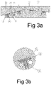
- the FIG 3A shows a cross section in which the fixing device (1) is multiple and has a double angle shape.
- the geometry of the fixing device (1) shown in the FIG 3A is an embodiment where the part (2) to be fixed has two slopes which may or may not have the same inclination, but where two different types of adhesion elements are applied.
- the surface (3) is that which delimits the contact zone between the fixing device (1) and the part to be fixed (2). In this exemplary embodiment, the surface (3) is flat, even if all other geometries such as concave, convex or curved surfaces are generally included in the subject of the invention.
- FIG 3A Two thrust systems are detailed in the device represented on the FIG 3A .
- the manual system (according to the enlarged "H” detail which constitutes the FIG 3B ) is shown on the left side and the Autonomous System on the right side (from the expanded "I” detail that is the FIG 3C ).
- the fixing device (1) comprises transversely holes for the installation of the heating elements (1 1). These heating elements (11) are placed as close as possible to the cavities (5) where the reversible adhesive (21) is located to avoid heat loss which prolongs its activation time.
- the fixing device (1) comprises orifices (12) through which the cooling element moves. These orifices (12) must in turn be as close as possible to the reversible adhesive pads (21), to reduce the cooling time.
- this Figure 3A also details the temporary fixing system by means of the screws (32) which are used before fixing the parts (2) using the bonding provided by the reversible adhesive (21).
- the cavities (5) in the radial direction recover the essential connecting elements for fixing the part (2).
- these cavities (5) are placed the reversible adhesive pads (21), the support plates (22) and in this specific case, a manual pushing system (43) which puts pressure on the reversible adhesive (21 ) against part (2).
- These manual push elements (43) are controlled with a torque wrench to ensure the necessary push of the reversible adhesive (21) against the part (2) to be fixed. See FIG 3A and FIG 3B
- the FIG 3C details an autonomous system for pushing the reversible adhesive (21) against the part (2) to be fixed which includes, in addition to the reversible adhesive (21), a support plate (22) and the spring washer (23 ).
- the depth of the cavity (5) and the heights of the reversible adhesive (21), the support plate (22) and the spring washer (23) indicate how much the spring washer (23) will be compressed, and by therefore the force it will exert on the reversible adhesive (21) in the vertical direction.
- the FIG 4A shows an independent or individual fixing device (1) with flat support for the part (2) to be fixed (not shown).
- the contact surface (3) has a larger diameter than the vertical cavity (5) where the adhesive (not shown) is housed. This difference in diameter allows the part (2) to be fixed to be well supported on the area outside the reversible adhesive (21).
- this fixing device (1) has a normally cylindrical shape (41) which gives it both finesse and rigidity. They are totally movable.
- the base is sealed by the cover (42).
- the detail of the FIG 4B shows that on the vertical cavity (5) cited, are the thrust element (23), the support plate (22) and the reversible adhesive (21).
- FIG 4C offers a view similar to FIG 4A and FIG 4B with part (2) since it is a built-in fastener.
- the holes (31) pass through in such a way that, by means of screws (32), they can be fixed to a fixed part (base or connecting element such as can be the machine table).
- FIG 5A shows an independent or individual fixing device (1) with oscillating support for the part to be fixed (not shown).
- This oscillation capacity makes it possible to fix parts (2) with inclined faces.
- the contact surface (3) has a larger diameter than the vertical cavity (5) where the reversible adhesive (21) is housed. This difference in diameter allows the part (2) to be fixed to be well supported on the area outside the reversible adhesive (21).
- this fixing device (1) has a normally cylindrical shape (52) which gives it both finesse and rigidity.
- This device comprises on the lower part a system for connecting to another support or extensions which allow it to be fixed to a fixed part (base or connecting element such as the table of the machine).
- FIG 5A further shows the heating elements (1 1), the orifices (12) of the refrigeration circuit and the temperature control probe (13).
- the thrust element (23), the support plate (22) and the reversible adhesive (21) which are detailed on the FIG 5B .
Landscapes
- Chemical & Material Sciences (AREA)
- Organic Chemistry (AREA)
- Chemical Kinetics & Catalysis (AREA)
- Health & Medical Sciences (AREA)
- Medicinal Chemistry (AREA)
- Polymers & Plastics (AREA)
- Engineering & Computer Science (AREA)
- Mechanical Engineering (AREA)
- Inorganic Chemistry (AREA)
- Adhesives Or Adhesive Processes (AREA)
- Lining Or Joining Of Plastics Or The Like (AREA)
- Jigs For Machine Tools (AREA)
Claims (11)
- System zum Befestigen/Ablösung von Werkstücken an/von einer Werkzeugmaschine mittels reversiblem Klebstoff; dadurch gekennzeichnet, dass es umfasst:a1) eine Befestigungsvorrichtung (1), die mit einer Außenfläche (3) in Kontakt mit dem zu bearbeitenden Werkstück (2) versehen ist; auf dieser Außenfläche (3) Hohlräume (5) aufweist, in denen ein reversibler Klebstoff (21) untergebracht ist, der eine physikalische Mischung aus Polycaprolacton mit Epoxidharz auf der Basis von Diglycidylether von Bisphenol A und von 4,4'-Sulfonyldianilin ist;a2) Heizelemente (11) des reversiblen Klebers (21);a3) einen Kühlkreislauf (12) für den reversiblen Klebstoff (21).a4) Kompressions- und Schiebemittel des reversiblen Klebers (21) zwischen der Befestigungsvorrichtung (1) und dem zu befestigenden Werkstück (2),und andererseits darin, dass b)die Befestigungsvorrichtung (1) unter dem reversiblen Kleber (21) eine Stützplatte aufweist, die die gleiche Form wie der reversible Kleber (21) hat und durch Zusammendrücken und Schieben mittels des reversiblen Klebers (21) betätigbar ist.
- System nach Anspruch 1, dadurch gekennzeichnet, dass das zu bearbeitende Werkstück (2) immer befestigt wird, indem es auf dem Befestigungsteil der Befestigungsvorrichtung (1) gestützt wird; wobei diese Befestigungsvorrichtung (1) ferner die zum Positionieren und Ausrichten des zu bearbeitenden Werkstücks (2) erforderlichen Elemente aufweist.
- System nach Anspruch 1, dadurch gekennzeichnet, dass die Befestigungsvorrichtung (1) einen einzigen unabhängigen Befestigungspunkt aufweist, wobei der Klebstoff ein Pad ist, was dazu führt, dass nur ein Klebepad (21) in dem Hohlraum (5) vorhanden ist.
- System nach Anspruch 1, dadurch gekennzeichnet, dass die Befestigungsvorrichtung (1) mehrere Befestigungspunkte aufweist, was zu mehreren reversiblen Klebepads (21) mit einem Pad pro Hohlraum (5) führt.
- System nach Anspruch 3, dadurch gekennzeichnet, dass die Verbindungsfläche der Befestigungsvorrichtung (1) ein zylindrischer Körper mit einem Außendurchmesser ist, der größer als die Fläche ist, die von dem reversiblen Klebstoff (21) eingenommen wird.
- System, nach Anspruch 5, dadurch gekennzeichnet, dass die Auflagefläche des Werkstücks (2) an der Befestigungsvorrichtung (1) befestigt ist.
- System nach Anspruch 5, dadurch gekennzeichnet, dass die Auflagefläche des Werkstücks (2) auf der Befestigungsvorrichtung (1) eine Schwingfähigkeit aufweist, die es erlaubt, die Werkstücke (2) mit schrägen Flächen zu befestigen.
- System nach Anspruch 4, dadurch gekennzeichnet, dass die Befestigungsvorrichtung (1) ein Körper beliebiger Geometrie ist, auf dem verschiedene Hohlräume (5) verteilt sind, um den reversiblen Klebstoff (21) aufzunehmen; dieser Körper ist dünn.
- System nach Anspruch 1, dadurch gekennzeichnet, dass die Heizelemente (11) innerhalb der Befestigungsvorrichtung (1) angeordnet sind; diese Heizelemente (11) sind elektrische Widerstände oder Heißluftpistolen.
- System nach Anspruch 1, dadurch gekennzeichnet, dass die Heizelemente (11) Temperatursensoren (13) umfassen.
- Verfahren zur Befestigung und Ablösung unter Verwendung des Systems nach Anspruch 1, dadurch gekennzeichnet, dass nach diesem dasselbe Verfahren erfolgta) die Befestigung erfolgt, indem folgende Handlungen durchgeführt werden:a1) Auflegen des zu bearbeitenden Teils (2) auf die Außenfläche (3) der Befestigungsvorrichtung (1)a2) Zusammenspannen der Befestigungsvorrichtung (1) und des zu bearbeitenden Werkstücks (2).a3) Verbinden der Heizelemente (11) und Erhitzen des reversiblen Klebers (21), bis etwa die Temperatur von 120°C ± 10°C erreicht ista4) Ablösen der Heizelemente (11) und Abkühlen der Anordnungb) Werkstück (2) bearbeiten; undc) Durchführen des Ablösens, Verbinden der Heizelemente (11), bis der reversible Klebstoff (21) eine Temperatur von ungefähr 50°C ± 10°C erreicht, wobei das Werkstück gelöst wird (2).
Applications Claiming Priority (1)
| Application Number | Priority Date | Filing Date | Title |
|---|---|---|---|
| ES201630091A ES2627331B1 (es) | 2016-01-26 | 2016-01-26 | Sistema y procedimiento de sujeción/desafijación de piezas a una máquina-herramienta por medio de un adhesivo reversible, y uso de dicho adhesivo reversible. |
Publications (2)
| Publication Number | Publication Date |
|---|---|
| EP3199294A1 EP3199294A1 (de) | 2017-08-02 |
| EP3199294B1 true EP3199294B1 (de) | 2022-09-07 |
Family
ID=58108566
Family Applications (1)
| Application Number | Title | Priority Date | Filing Date |
|---|---|---|---|
| EP17382033.3A Active EP3199294B1 (de) | 2016-01-26 | 2017-01-26 | System und verfahren zur befestigung/ablösung von werkstücken auf einer werkzeugmaschine mithilfe eines reversiblen haftklebers, und verwendung dieses reversiblen haftklebers |
Country Status (2)
| Country | Link |
|---|---|
| EP (1) | EP3199294B1 (de) |
| ES (1) | ES2627331B1 (de) |
Families Citing this family (2)
| Publication number | Priority date | Publication date | Assignee | Title |
|---|---|---|---|---|
| IT201900000217A1 (it) * | 2019-01-08 | 2020-07-08 | Luca Mariotti | Procedimento per produrre un frontale di una montatura per occhiali |
| ES2852674B2 (es) * | 2020-03-10 | 2022-06-27 | Fresmak Sa | Composición adhesiva de uso térmicamente reversible |
Family Cites Families (3)
| Publication number | Priority date | Publication date | Assignee | Title |
|---|---|---|---|---|
| FR2624872B1 (fr) * | 1987-12-22 | 1991-10-18 | Elf Aquitaine | Formulation adhesive acrylique anaerobie stable chimiquement et susceptible de fournir un joint adhesif durci presentant des resistances ameliorees au choc et au cisaillement ou/et une bonne tenue thermique |
| JP2002052430A (ja) * | 2000-08-07 | 2002-02-19 | Kanetec Co Ltd | 工作物固定装置 |
| BR112015008189A2 (pt) * | 2012-10-19 | 2017-07-04 | Dow Global Technologies Llc | composição, processo para sua preparação e compósito |
-
2016
- 2016-01-26 ES ES201630091A patent/ES2627331B1/es active Active
-
2017
- 2017-01-26 EP EP17382033.3A patent/EP3199294B1/de active Active
Also Published As
| Publication number | Publication date |
|---|---|
| EP3199294A1 (de) | 2017-08-02 |
| ES2627331R1 (es) | 2017-11-13 |
| ES2627331A2 (es) | 2017-07-27 |
| ES2627331B1 (es) | 2018-09-12 |
Similar Documents
| Publication | Publication Date | Title |
|---|---|---|
| FR2853378A1 (fr) | Plaquettes de frein a disque ventilees | |
| BE1018825A3 (fr) | Dissipateur thermique pour un composant electronique ou electrique. | |
| FR2607045A1 (fr) | Procede de jonction d'objets en superalliage a base de nickel et ensemble de feuillards mis en oeuvre dans ce procede | |
| KR20080032018A (ko) | 열 전달 합성물, 열 전달 합성물 제조 방법 및 열 전달 디바이스 | |
| FR2960464A1 (fr) | Procede et outillage de manutention d'un insert pour son implantation dans un panneau alveolaire et son retrait hors de ce panneau | |
| EP3199294A1 (de) | System und verfahren zur befestigung/ablösung von werkstücken auf einer werkzeugmaschine mithilfe eines reversiblen haftklebers, und verwendung dieses reversiblen haftklebers | |
| EP0578608B1 (de) | Verfahren und Vorrichtung zum Werkstückhalten durch Einfrieren | |
| WO2012076809A1 (fr) | Thermo-generateur et procede de realisation de thermo-generateur | |
| FR2718317A1 (fr) | Combinaison d'éléments de construction. | |
| CH691797A5 (fr) | Appareil d'usinage par électroérosion. | |
| EP3979776A1 (de) | Thermischer schalter mit passivem betätiger zur thermischen verbindung zwischen zwei zylindrischen elementen und bordystem mit einem solchen schalter | |
| FR2534108A1 (fr) | Procede et appareil perfectionnes de scellement hermetique | |
| FR3033716A1 (fr) | Marteau a percussion pour pulveriser un materiau, en particulier des rochers | |
| FR2860179A1 (fr) | Procede de thermoscellage et dispositif pour la mise en oeuvre de ce procede | |
| FR2458599A1 (fr) | Cible a bombardement ionique montee sur un support | |
| EP1283760B1 (de) | Struktur einer spannvorrichtung zum positionieren und spannen eines stückes zur bearbeitung | |
| FR3060942A1 (fr) | Procede de fabrication d'un ensemble comprenant une structure mecanique et un composant de puissance electrique pour un aeronef | |
| EP0490756A1 (de) | Verfahren zur Herstellung eines aus einem bei Umgebungstemperatur nicht-schmiedbaren Material bestehenden Teiles, und entsprechendes Werkzeug | |
| FR2937391A1 (fr) | Dispositif de freinage a commande hydraulique comportant une capsule amovible de refroidissement par changement d'etat. | |
| BE1006695A5 (fr) | Appareil de maintien de gemme. | |
| Torres et al. | A finite element modeling of thermal residual stresses during brazing of diamond to tungsten carbide | |
| GB2453135A (en) | Bonding Method and Component for use therein | |
| CN107866740B (zh) | 硅聚晶烧结物及其制造方法 | |
| CN102130077A (zh) | 具有单层钻石颗粒的均热板及其相关方法 | |
| US20100163075A1 (en) | Method for thermal deburring |
Legal Events
| Date | Code | Title | Description |
|---|---|---|---|
| PUAI | Public reference made under article 153(3) epc to a published international application that has entered the european phase |
Free format text: ORIGINAL CODE: 0009012 |
|
| STAA | Information on the status of an ep patent application or granted ep patent |
Free format text: STATUS: THE APPLICATION HAS BEEN PUBLISHED |
|
| AK | Designated contracting states |
Kind code of ref document: A1 Designated state(s): AL AT BE BG CH CY CZ DE DK EE ES FI FR GB GR HR HU IE IS IT LI LT LU LV MC MK MT NL NO PL PT RO RS SE SI SK SM TR |
|
| AX | Request for extension of the european patent |
Extension state: BA ME |
|
| STAA | Information on the status of an ep patent application or granted ep patent |
Free format text: STATUS: REQUEST FOR EXAMINATION WAS MADE |
|
| 17P | Request for examination filed |
Effective date: 20180202 |
|
| RBV | Designated contracting states (corrected) |
Designated state(s): AL AT BE BG CH CY CZ DE DK EE ES FI FR GB GR HR HU IE IS IT LI LT LU LV MC MK MT NL NO PL PT RO RS SE SI SK SM TR |
|
| STAA | Information on the status of an ep patent application or granted ep patent |
Free format text: STATUS: EXAMINATION IS IN PROGRESS |
|
| 17Q | First examination report despatched |
Effective date: 20190409 |
|
| GRAP | Despatch of communication of intention to grant a patent |
Free format text: ORIGINAL CODE: EPIDOSNIGR1 |
|
| STAA | Information on the status of an ep patent application or granted ep patent |
Free format text: STATUS: GRANT OF PATENT IS INTENDED |
|
| INTG | Intention to grant announced |
Effective date: 20220517 |
|
| GRAS | Grant fee paid |
Free format text: ORIGINAL CODE: EPIDOSNIGR3 |
|
| GRAA | (expected) grant |
Free format text: ORIGINAL CODE: 0009210 |
|
| STAA | Information on the status of an ep patent application or granted ep patent |
Free format text: STATUS: THE PATENT HAS BEEN GRANTED |
|
| AK | Designated contracting states |
Kind code of ref document: B1 Designated state(s): AL AT BE BG CH CY CZ DE DK EE ES FI FR GB GR HR HU IE IS IT LI LT LU LV MC MK MT NL NO PL PT RO RS SE SI SK SM TR |
|
| REG | Reference to a national code |
Ref country code: GB Ref legal event code: FG4D Free format text: NOT ENGLISH |
|
| REG | Reference to a national code |
Ref country code: CH Ref legal event code: EP Ref country code: AT Ref legal event code: REF Ref document number: 1516636 Country of ref document: AT Kind code of ref document: T Effective date: 20220915 |
|
| REG | Reference to a national code |
Ref country code: IE Ref legal event code: FG4D Free format text: LANGUAGE OF EP DOCUMENT: FRENCH |
|
| REG | Reference to a national code |
Ref country code: DE Ref legal event code: R096 Ref document number: 602017061459 Country of ref document: DE |
|
| REG | Reference to a national code |
Ref country code: NL Ref legal event code: FP |
|
| REG | Reference to a national code |
Ref country code: LT Ref legal event code: MG9D |
|
| PG25 | Lapsed in a contracting state [announced via postgrant information from national office to epo] |
Ref country code: SE Free format text: LAPSE BECAUSE OF FAILURE TO SUBMIT A TRANSLATION OF THE DESCRIPTION OR TO PAY THE FEE WITHIN THE PRESCRIBED TIME-LIMIT Effective date: 20220907 Ref country code: RS Free format text: LAPSE BECAUSE OF FAILURE TO SUBMIT A TRANSLATION OF THE DESCRIPTION OR TO PAY THE FEE WITHIN THE PRESCRIBED TIME-LIMIT Effective date: 20220907 Ref country code: NO Free format text: LAPSE BECAUSE OF FAILURE TO SUBMIT A TRANSLATION OF THE DESCRIPTION OR TO PAY THE FEE WITHIN THE PRESCRIBED TIME-LIMIT Effective date: 20221207 Ref country code: LV Free format text: LAPSE BECAUSE OF FAILURE TO SUBMIT A TRANSLATION OF THE DESCRIPTION OR TO PAY THE FEE WITHIN THE PRESCRIBED TIME-LIMIT Effective date: 20220907 Ref country code: LT Free format text: LAPSE BECAUSE OF FAILURE TO SUBMIT A TRANSLATION OF THE DESCRIPTION OR TO PAY THE FEE WITHIN THE PRESCRIBED TIME-LIMIT Effective date: 20220907 Ref country code: FI Free format text: LAPSE BECAUSE OF FAILURE TO SUBMIT A TRANSLATION OF THE DESCRIPTION OR TO PAY THE FEE WITHIN THE PRESCRIBED TIME-LIMIT Effective date: 20220907 |
|
| REG | Reference to a national code |
Ref country code: AT Ref legal event code: MK05 Ref document number: 1516636 Country of ref document: AT Kind code of ref document: T Effective date: 20220907 |
|
| PG25 | Lapsed in a contracting state [announced via postgrant information from national office to epo] |
Ref country code: HR Free format text: LAPSE BECAUSE OF FAILURE TO SUBMIT A TRANSLATION OF THE DESCRIPTION OR TO PAY THE FEE WITHIN THE PRESCRIBED TIME-LIMIT Effective date: 20220907 Ref country code: GR Free format text: LAPSE BECAUSE OF FAILURE TO SUBMIT A TRANSLATION OF THE DESCRIPTION OR TO PAY THE FEE WITHIN THE PRESCRIBED TIME-LIMIT Effective date: 20221208 |
|
| PG25 | Lapsed in a contracting state [announced via postgrant information from national office to epo] |
Ref country code: SM Free format text: LAPSE BECAUSE OF FAILURE TO SUBMIT A TRANSLATION OF THE DESCRIPTION OR TO PAY THE FEE WITHIN THE PRESCRIBED TIME-LIMIT Effective date: 20220907 Ref country code: RO Free format text: LAPSE BECAUSE OF FAILURE TO SUBMIT A TRANSLATION OF THE DESCRIPTION OR TO PAY THE FEE WITHIN THE PRESCRIBED TIME-LIMIT Effective date: 20220907 Ref country code: PT Free format text: LAPSE BECAUSE OF FAILURE TO SUBMIT A TRANSLATION OF THE DESCRIPTION OR TO PAY THE FEE WITHIN THE PRESCRIBED TIME-LIMIT Effective date: 20230109 Ref country code: CZ Free format text: LAPSE BECAUSE OF FAILURE TO SUBMIT A TRANSLATION OF THE DESCRIPTION OR TO PAY THE FEE WITHIN THE PRESCRIBED TIME-LIMIT Effective date: 20220907 Ref country code: AT Free format text: LAPSE BECAUSE OF FAILURE TO SUBMIT A TRANSLATION OF THE DESCRIPTION OR TO PAY THE FEE WITHIN THE PRESCRIBED TIME-LIMIT Effective date: 20220907 |
|
| PG25 | Lapsed in a contracting state [announced via postgrant information from national office to epo] |
Ref country code: SK Free format text: LAPSE BECAUSE OF FAILURE TO SUBMIT A TRANSLATION OF THE DESCRIPTION OR TO PAY THE FEE WITHIN THE PRESCRIBED TIME-LIMIT Effective date: 20220907 Ref country code: PL Free format text: LAPSE BECAUSE OF FAILURE TO SUBMIT A TRANSLATION OF THE DESCRIPTION OR TO PAY THE FEE WITHIN THE PRESCRIBED TIME-LIMIT Effective date: 20220907 Ref country code: IS Free format text: LAPSE BECAUSE OF FAILURE TO SUBMIT A TRANSLATION OF THE DESCRIPTION OR TO PAY THE FEE WITHIN THE PRESCRIBED TIME-LIMIT Effective date: 20230107 Ref country code: EE Free format text: LAPSE BECAUSE OF FAILURE TO SUBMIT A TRANSLATION OF THE DESCRIPTION OR TO PAY THE FEE WITHIN THE PRESCRIBED TIME-LIMIT Effective date: 20220907 |
|
| REG | Reference to a national code |
Ref country code: DE Ref legal event code: R097 Ref document number: 602017061459 Country of ref document: DE |
|
| PG25 | Lapsed in a contracting state [announced via postgrant information from national office to epo] |
Ref country code: AL Free format text: LAPSE BECAUSE OF FAILURE TO SUBMIT A TRANSLATION OF THE DESCRIPTION OR TO PAY THE FEE WITHIN THE PRESCRIBED TIME-LIMIT Effective date: 20220907 |
|
| PLBE | No opposition filed within time limit |
Free format text: ORIGINAL CODE: 0009261 |
|
| STAA | Information on the status of an ep patent application or granted ep patent |
Free format text: STATUS: NO OPPOSITION FILED WITHIN TIME LIMIT |
|
| PG25 | Lapsed in a contracting state [announced via postgrant information from national office to epo] |
Ref country code: DK Free format text: LAPSE BECAUSE OF FAILURE TO SUBMIT A TRANSLATION OF THE DESCRIPTION OR TO PAY THE FEE WITHIN THE PRESCRIBED TIME-LIMIT Effective date: 20220907 |
|
| 26N | No opposition filed |
Effective date: 20230608 |
|
| PG25 | Lapsed in a contracting state [announced via postgrant information from national office to epo] |
Ref country code: SI Free format text: LAPSE BECAUSE OF FAILURE TO SUBMIT A TRANSLATION OF THE DESCRIPTION OR TO PAY THE FEE WITHIN THE PRESCRIBED TIME-LIMIT Effective date: 20220907 |
|
| PG25 | Lapsed in a contracting state [announced via postgrant information from national office to epo] |
Ref country code: LU Free format text: LAPSE BECAUSE OF NON-PAYMENT OF DUE FEES Effective date: 20230126 |
|
| REG | Reference to a national code |
Ref country code: BE Ref legal event code: MM Effective date: 20230131 |
|
| P01 | Opt-out of the competence of the unified patent court (upc) registered |
Effective date: 20231011 |
|
| PG25 | Lapsed in a contracting state [announced via postgrant information from national office to epo] |
Ref country code: BE Free format text: LAPSE BECAUSE OF NON-PAYMENT OF DUE FEES Effective date: 20230131 |
|
| PG25 | Lapsed in a contracting state [announced via postgrant information from national office to epo] |
Ref country code: IE Free format text: LAPSE BECAUSE OF NON-PAYMENT OF DUE FEES Effective date: 20230126 |
|
| PG25 | Lapsed in a contracting state [announced via postgrant information from national office to epo] |
Ref country code: IT Free format text: LAPSE BECAUSE OF FAILURE TO SUBMIT A TRANSLATION OF THE DESCRIPTION OR TO PAY THE FEE WITHIN THE PRESCRIBED TIME-LIMIT Effective date: 20220907 |
|
| PG25 | Lapsed in a contracting state [announced via postgrant information from national office to epo] |
Ref country code: MC Free format text: LAPSE BECAUSE OF FAILURE TO SUBMIT A TRANSLATION OF THE DESCRIPTION OR TO PAY THE FEE WITHIN THE PRESCRIBED TIME-LIMIT Effective date: 20220907 |
|
| PG25 | Lapsed in a contracting state [announced via postgrant information from national office to epo] |
Ref country code: MC Free format text: LAPSE BECAUSE OF FAILURE TO SUBMIT A TRANSLATION OF THE DESCRIPTION OR TO PAY THE FEE WITHIN THE PRESCRIBED TIME-LIMIT Effective date: 20220907 |
|
| PG25 | Lapsed in a contracting state [announced via postgrant information from national office to epo] |
Ref country code: ES Free format text: LAPSE BECAUSE OF FAILURE TO SUBMIT A TRANSLATION OF THE DESCRIPTION OR TO PAY THE FEE WITHIN THE PRESCRIBED TIME-LIMIT Effective date: 20220907 |
|
| PG25 | Lapsed in a contracting state [announced via postgrant information from national office to epo] |
Ref country code: ES Free format text: LAPSE BECAUSE OF FAILURE TO SUBMIT A TRANSLATION OF THE DESCRIPTION OR TO PAY THE FEE WITHIN THE PRESCRIBED TIME-LIMIT Effective date: 20220907 |
|
| PG25 | Lapsed in a contracting state [announced via postgrant information from national office to epo] |
Ref country code: BG Free format text: LAPSE BECAUSE OF FAILURE TO SUBMIT A TRANSLATION OF THE DESCRIPTION OR TO PAY THE FEE WITHIN THE PRESCRIBED TIME-LIMIT Effective date: 20220907 |
|
| PG25 | Lapsed in a contracting state [announced via postgrant information from national office to epo] |
Ref country code: BG Free format text: LAPSE BECAUSE OF FAILURE TO SUBMIT A TRANSLATION OF THE DESCRIPTION OR TO PAY THE FEE WITHIN THE PRESCRIBED TIME-LIMIT Effective date: 20220907 |
|
| PG25 | Lapsed in a contracting state [announced via postgrant information from national office to epo] |
Ref country code: CY Free format text: LAPSE BECAUSE OF FAILURE TO SUBMIT A TRANSLATION OF THE DESCRIPTION OR TO PAY THE FEE WITHIN THE PRESCRIBED TIME-LIMIT; INVALID AB INITIO Effective date: 20170126 |
|
| PG25 | Lapsed in a contracting state [announced via postgrant information from national office to epo] |
Ref country code: HU Free format text: LAPSE BECAUSE OF FAILURE TO SUBMIT A TRANSLATION OF THE DESCRIPTION OR TO PAY THE FEE WITHIN THE PRESCRIBED TIME-LIMIT; INVALID AB INITIO Effective date: 20170126 |
|
| PG25 | Lapsed in a contracting state [announced via postgrant information from national office to epo] |
Ref country code: TR Free format text: LAPSE BECAUSE OF FAILURE TO SUBMIT A TRANSLATION OF THE DESCRIPTION OR TO PAY THE FEE WITHIN THE PRESCRIBED TIME-LIMIT Effective date: 20220907 |
|
| REG | Reference to a national code |
Ref country code: CH Ref legal event code: U11 Free format text: ST27 STATUS EVENT CODE: U-0-0-U10-U11 (AS PROVIDED BY THE NATIONAL OFFICE) Effective date: 20260201 |
|
| PGFP | Annual fee paid to national office [announced via postgrant information from national office to epo] |
Ref country code: NL Payment date: 20260126 Year of fee payment: 10 |
|
| PGFP | Annual fee paid to national office [announced via postgrant information from national office to epo] |
Ref country code: GB Payment date: 20260126 Year of fee payment: 10 |
|
| PGFP | Annual fee paid to national office [announced via postgrant information from national office to epo] |
Ref country code: DE Payment date: 20260123 Year of fee payment: 10 |
|
| PGFP | Annual fee paid to national office [announced via postgrant information from national office to epo] |
Ref country code: FR Payment date: 20260126 Year of fee payment: 10 |
|
| PGFP | Annual fee paid to national office [announced via postgrant information from national office to epo] |
Ref country code: CH Payment date: 20260201 Year of fee payment: 10 |