EP3198952B1 - Leistungsadaption und -randomisierung interferenzunterdrückung und -minderung - Google Patents
Leistungsadaption und -randomisierung interferenzunterdrückung und -minderung Download PDFInfo
- Publication number
- EP3198952B1 EP3198952B1 EP15750862.3A EP15750862A EP3198952B1 EP 3198952 B1 EP3198952 B1 EP 3198952B1 EP 15750862 A EP15750862 A EP 15750862A EP 3198952 B1 EP3198952 B1 EP 3198952B1
- Authority
- EP
- European Patent Office
- Prior art keywords
- transmission power
- resource element
- indication
- transmission
- downlink transmission
- Prior art date
- Legal status (The legal status is an assumption and is not a legal conclusion. Google has not performed a legal analysis and makes no representation as to the accuracy of the status listed.)
- Active
Links
- 230000005540 biological transmission Effects 0.000 claims description 172
- 238000000034 method Methods 0.000 claims description 42
- 238000012545 processing Methods 0.000 claims description 21
- 238000001514 detection method Methods 0.000 claims description 8
- 230000004044 response Effects 0.000 claims description 4
- 230000008054 signal transmission Effects 0.000 claims description 2
- 238000004891 communication Methods 0.000 description 32
- 238000010586 diagram Methods 0.000 description 18
- 230000015654 memory Effects 0.000 description 14
- 230000006978 adaptation Effects 0.000 description 13
- 238000013459 approach Methods 0.000 description 9
- 230000002452 interceptive effect Effects 0.000 description 4
- 230000008569 process Effects 0.000 description 4
- 230000009471 action Effects 0.000 description 2
- 230000008901 benefit Effects 0.000 description 2
- 238000004590 computer program Methods 0.000 description 2
- 230000001419 dependent effect Effects 0.000 description 2
- 230000000116 mitigating effect Effects 0.000 description 2
- 238000013468 resource allocation Methods 0.000 description 2
- 239000007787 solid Substances 0.000 description 2
- 230000003595 spectral effect Effects 0.000 description 2
- 230000010267 cellular communication Effects 0.000 description 1
- 230000000694 effects Effects 0.000 description 1
- 230000005670 electromagnetic radiation Effects 0.000 description 1
- 238000001914 filtration Methods 0.000 description 1
- 230000006870 function Effects 0.000 description 1
- 230000007774 longterm Effects 0.000 description 1
- 238000004519 manufacturing process Methods 0.000 description 1
- 230000007246 mechanism Effects 0.000 description 1
- 238000010295 mobile communication Methods 0.000 description 1
- 238000012986 modification Methods 0.000 description 1
- 230000004048 modification Effects 0.000 description 1
- 230000003287 optical effect Effects 0.000 description 1
- 230000002085 persistent effect Effects 0.000 description 1
- 230000010363 phase shift Effects 0.000 description 1
- 230000000135 prohibitive effect Effects 0.000 description 1
- 238000000926 separation method Methods 0.000 description 1
- 230000011664 signaling Effects 0.000 description 1
- 239000000126 substance Substances 0.000 description 1
- 230000002123 temporal effect Effects 0.000 description 1
- 238000012546 transfer Methods 0.000 description 1
- 230000001131 transforming effect Effects 0.000 description 1
- 239000002699 waste material Substances 0.000 description 1
Images






Classifications
-
- H—ELECTRICITY
- H04—ELECTRIC COMMUNICATION TECHNIQUE
- H04W—WIRELESS COMMUNICATION NETWORKS
- H04W52/00—Power management, e.g. Transmission Power Control [TPC] or power classes
- H04W52/04—Transmission power control [TPC]
- H04W52/18—TPC being performed according to specific parameters
- H04W52/24—TPC being performed according to specific parameters using SIR [Signal to Interference Ratio] or other wireless path parameters
- H04W52/243—TPC being performed according to specific parameters using SIR [Signal to Interference Ratio] or other wireless path parameters taking into account interferences
-
- H—ELECTRICITY
- H04—ELECTRIC COMMUNICATION TECHNIQUE
- H04B—TRANSMISSION
- H04B7/00—Radio transmission systems, i.e. using radiation field
- H04B7/02—Diversity systems; Multi-antenna system, i.e. transmission or reception using multiple antennas
- H04B7/04—Diversity systems; Multi-antenna system, i.e. transmission or reception using multiple antennas using two or more spaced independent antennas
- H04B7/0413—MIMO systems
-
- H—ELECTRICITY
- H04—ELECTRIC COMMUNICATION TECHNIQUE
- H04W—WIRELESS COMMUNICATION NETWORKS
- H04W72/00—Local resource management
- H04W72/50—Allocation or scheduling criteria for wireless resources
- H04W72/54—Allocation or scheduling criteria for wireless resources based on quality criteria
- H04W72/541—Allocation or scheduling criteria for wireless resources based on quality criteria using the level of interference
-
- H—ELECTRICITY
- H04—ELECTRIC COMMUNICATION TECHNIQUE
- H04W—WIRELESS COMMUNICATION NETWORKS
- H04W24/00—Supervisory, monitoring or testing arrangements
- H04W24/02—Arrangements for optimising operational condition
-
- H—ELECTRICITY
- H04—ELECTRIC COMMUNICATION TECHNIQUE
- H04W—WIRELESS COMMUNICATION NETWORKS
- H04W24/00—Supervisory, monitoring or testing arrangements
- H04W24/08—Testing, supervising or monitoring using real traffic
-
- H—ELECTRICITY
- H04—ELECTRIC COMMUNICATION TECHNIQUE
- H04W—WIRELESS COMMUNICATION NETWORKS
- H04W52/00—Power management, e.g. Transmission Power Control [TPC] or power classes
- H04W52/04—Transmission power control [TPC]
- H04W52/06—TPC algorithms
- H04W52/10—Open loop power control
-
- H—ELECTRICITY
- H04—ELECTRIC COMMUNICATION TECHNIQUE
- H04W—WIRELESS COMMUNICATION NETWORKS
- H04W52/00—Power management, e.g. Transmission Power Control [TPC] or power classes
- H04W52/04—Transmission power control [TPC]
- H04W52/06—TPC algorithms
- H04W52/14—Separate analysis of uplink or downlink
- H04W52/143—Downlink power control
Definitions
- Embodiments of the present invention relate generally to the technical field of data processing, and more particularly, to computer devices operable to communicate data over a network.
- Interference associated with co-scheduled user equipment such as in multiuser multiple input/multiple output environments, or from neighboring cell UEs may impede cellular communication.
- One approach to mitigating interference is to schedule UEs on orthogonal frequency-time resources. This scheduling approach, however, may waste some resources, particularly where UEs already have appreciable spatial separation.
- coordinating resources across cells may be challenging for cell-edge UEs. While semi-static resource allocation, such as enhanced inter-cell interference coordination (“elCIC”) or fractional frequency reuse (“FFR”) may be employed, resource allocation and the adaption thereof may be complex.
- elCIC enhanced inter-cell interference coordination
- FFR fractional frequency reuse
- MIMO multiple-input and multiple-output
- MU-MIMO multiple user MIMO
- MIMO coordination across cells may be employed.
- accurate channel state information may be necessary.
- accurate channel state information may be difficult to obtain.
- WO 2011/098655 A1 discloses an apparatus for providing interference cancellation, including a processor and memory including computer program code. which is configured to cause the apparatus to identify an interval of received signal power levels for interference cancellation of an interfering signal to a primary signal, and generate a message that provides the interval of received signal power levels for the interference cancellation of the interfering signal to the primary signal.
- HUAWEI ET AL "TP on Network Assisted IC”
- 3GPP DRAFT discloses a method of adopting an interference cancellation receiver, including receiving signaling of a transmission power associated with a first resource element, receiving a high signal shared control channel (HS-SCCH) by a network assisted interference cancellation user equipment and performing interference cancellation based on the indication of the transmission power.
- HS-SCCH high signal shared control channel
- phrases “A or B” and “A and/or B” means (A), (B), or (A and B).
- phrase “A, B, and/or C” means (A), (B), (C), (A and B), (A and C), (B and C), or (A, B, and C).
- module and/or “logic” may refer to, be part of, or include an Application Specific Integrated Circuit (“ASIC”), an electronic circuit, a processor (shared, dedicated, or group), and/or memory (shared, dedicated, or group) that execute one or more software or firmware programs, a combinational logic circuit, and/or other suitable hardware components that provide the described functionality.
- ASIC Application Specific Integrated Circuit
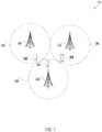
- a block diagram shows an environment 100 in which downlink transmission power levels may be adjusted to facilitate interference cancellation ("IC") at a UE, in accordance with various embodiments.
- the UEs 150-160 may be any type of computing device equipped with broadband circuitry and adapted to operate on a cell (e.g., the cells 120-130) according to, for example, one or more 3rd Generation Partnership Project ("3GPP") technical specifications.
- 3GPP 3rd Generation Partnership Project
- one of the UEs 150-160 may be a netbook, a tablet computer, a handheld computing device, a web-enabled appliance, a gaming device, a mobile phone, a smartphone, an eBook reader, a personal data assistant, or the like.
- one of the UEs 150-160 may be a computing device that is not primarily adapted for user communications (e.g., voice calling, text/instant messaging, web browsing), such as a smart metering device, payment device (e.g., a "pay-as-you-drive” device), a vending machine, a telematics system (e.g., a system adapted for tracking and tracing of vehicles), a security system (e.g., a surveillance device), and the like.
- a computing device that is not primarily adapted for user communications (e.g., voice calling, text/instant messaging, web browsing), such as a smart metering device, payment device (e.g., a "pay-as-you-drive” device), a vending machine, a telematics system (e.g., a system adapted for tracking and tracing of vehicles), a security system (e.g., a surveillance device), and the like.
- a smart metering device e
- the UEs 150-160 may be configured for intersystem communication by operating on one or more wireless cells 120-130.
- Each wireless cell 120-130 may be provided by a respective evolved Node B (“eNB").
- eNB evolved Node B
- the eNBs 105-115 may act as a mobility anchors towards a core network (not shown).
- the eNBs 105-115 may connect the UEs 150-160 to a core network, for example, as part of a third Generation (“3G"), fourth Generation (“4G”), fifth Generation (“5G”), or beyond system that adheres to one or more standards, such as Long Term Evolution (“LTE”), LTE-Advanced (“LTE-A”), or other similar standard.
- 3G Third Generation
- 4G fourth Generation
- 5G fifth Generation
- LTE Long Term Evolution
- LTE-A LTE-Advanced
- a first UE 150 may receive downlink transmissions from a first eNB 105.
- the downlink transmissions are to include a signal intended for the first UE 150.
- the downlink transmissions that include the signal may also include interference.
- another transmission from a second eNB 110 may include data at the same resources (e.g., time and/or frequency resources) as the intended signal. Therefore, the other transmission may reach the first UE 150 and interfere with the intended signal from the first eNB 105.
- the first UE 150 may be adapted to perform one or more interference cancellation ("IC") techniques.
- the first UE 150 may benefit from a discernable difference between the transmission power associated with the intended signal from the first eNB 105 and the transmission power associated with the interference signal from the second eNB 110.
- the first UE 150 may perform IC where the signal power level and the interference power level are different by several decibels ("dB").
- the first UE 150 may be adapted to perform IC regardless of whether the signal power level is greater than the interference power level or vice versa.
- the first UE 105 may be adapted for symbol-level IC.
- the UE 150 may be adapted to estimate what the intended signal is and begin decoding symbols from estimated intended signal. Symbols which cannot be sufficiently decoded may be treated with another non-IC decoding technique. Each symbols, and respective confidence levels, may then be processed by a channel decoder for codeword decoding.
- adjusting one or more transmission powers at one of the eNBs 105-115 may improve IC at the first UE 150. Such adjustments may be differently accomplished in embodiments.
- a first UE 150 that may receive interference with a signal may proactively request an adjustment to a transmission power.
- the first UE 150 may determine that a greater difference between the signal power level and the interference power level would facilitate IC at the first UE 150. Therefore, the first UE 150 may be adapted to generate a request for at least one of the eNBs 105-115 for an adjustment to a respective downlink transmission power.
- the request may simply be a request for an adjustment to a transmission power.
- the request may include an indication of whether an increase or a decrease in transmission power.
- the request may include an indication of a value for an increase or decrease in transmission power.
- the request may include an indication of one or more increments or decrements for an adjustment to a transmission power (e.g., an indication of value of a number of standard dB steps the transmitting node is to take up or down).
- the request may include a specific dB value.
- the first UE 150 may transmit the generated request to the first eNB 105, which serves the first UE 150. In another embodiment, the first UE 150 may transmit the generated request to another eNB 110, 115 that does not serve the first UE 150, i.e., an eNB that transmit the interference. In such embodiment, the first UE 150 may transmit the generated request using a common uplink channel that is allocated for UEs to request power adaptations to non-serving cells 125, 130.
- the receiving eNB 105-115 may adjust its downlink transmission power.
- the receiving eNB 105-115 may not adjust its downlink transmission power by the exact amount indicated by the request, but may take the request (e.g., a value included therein) into account when computing a downlink transmission power level that is satisfactory.
- the receiving eNB 105-115 may need to indicate to other UEs that the receiving eNB 105-115 has adjusted its transmission power level.
- the transmission power level between reference signal ("RS") signals and data signals may be different.
- a second eNB 110 that adjusts its transmission power based on a request from a first UE 150 that is not served by the second eNB 110 may need to notify a second UE 155 that is served by the second eNB 110.
- the transmission power level is the same for both the RS signals and the data signals (e.g., channel state information ("CSI") RS signals)
- CSI channel state information
- the receiving eNB 105-115 may need to adjust a power ratio between paired UEs.
- a first eNB 105 may randomize transmission powers associated with resource elements to facilitate IC at a first UE 150.
- This randomization may in fact be pseudorandom and may cause a difference of one or more dB between a signal power level intended for the first UE 150 and an interference power level from another eNB 110-115 received at the first UE 150.
- This randomization approach may reduce or eliminate the need for complex cross-cell coordination to mitigate interference and/or improve IC at a UE. Further, this randomization approach may address a number of interfering signals.
- the first eNB 105 may adjust one or more transmission powers associated with a resource on which the first UE 150 is served.
- the resource may be divided into chunks, or pluralities of resource elements.
- transmission powers for pluralities of resource elements may be different across the resource on which the first UE 150 is served.
- respective transmission powers for respective pluralities of resource elements may be based on a pseudorandom sequence.
- the pseudorandom sequence may be based on a seed, which the first eNB 105 may transmit to the first UE 150 so that the first UE 150 may have an indication of the respective transmission powers for respective pluralities of resource elements. Accordingly, the first UE 150 may be able to compute or estimate the signal power level to perform IC.
- the first UE 150 may account for a fluctuation in the signal from the first eNB 105 (e.g., an intended signal may fluctuate in a range of +3 or -3 dB).
- a fluctuation range may be transmitted to the first UE 150 by the first eNB 105.
- the fluctuation range may be implicitly embedded in the sequence so that where the first UE 150 generates the sequence from the seed, the first UE 150 also generates the fluctuation range.
- the first eNB 105 may transmit the fluctuation range to the first UE 150, for example, in a same or different message.
- a region on a resource map may be associated with power adaptation - e.g., a region may be dedicated to one or more UEs that proactively request transmission power adjustments and/or for which transmission power is randomized.
- a plurality of eNBs 105-115 may coordinate the region associated with power adaptation. This coordination may be slow coordination, for example, over an X2 interface. Each eNB 105-115 would then schedule respective UEs 150-160 in such a region to apply the power adjustment approaches disclosed herein.
- the plurality of eNBs 105-115 may be adapted to coordinate according to other embodiments.
- the plurality of eNBs 105-115 may coordinate a region on a resource map that only serves Quadrature Phase Shift Keying ("QPSK").
- QPSK Quadrature Phase Shift Keying
- a block diagram illustrates randomization of transmission power levels 210 for a plurality of resource elements 205, in accordance with various embodiments.
- an eNB may randomize downlink transmission powers associated with resource elements. This randomization may be based on a pseudorandom sequence, wherein the sequence may be generated from a seed.
- a downlink transmission for a UE may be comprised of a plurality of resource elements 205.
- the transmission power level 210 may be randomized for a plurality of resource elements.
- one or more resource elements 215 may be transmitted according to a first transmission power.
- the first transmission power may be based on a sequence, such as a dB value that is an element of a pseudorandom sequence.
- One or more other resource elements 220 may be transmitted according to a second transmission power, which may be lower than the first transmission power.
- the second transmission power may be also based on the sequence, such as another dB value that is an element of the pseudorandom sequence.
- One or more additional resource elements 225 may be transmitted according to a third transmission power, which may be different from the first and/or second transmission powers.
- the third transmission power may be also based on the sequence, such as an additional dB value that is an element of the pseudorandom sequence.
- a line graph illustrates a potential performance gain associated with randomization of transmission power, in accordance with various embodiments.
- the x-axis shows the signal-to-interference-plus-noise ratio ("SINR") when removing the two dominant interferers (in dB).
- the y-axis shows the rate achieved (e.g., spectral efficiency) in bits/second/hertz ("bit/s/Hz").
- a first curve 305 illustrates performance when symbol-level IC is applied with an IC threshold of five (5) dB.
- a second curve 310 illustrates performance when IC is not applied.
- a third curve 315 illustrates performance when there is no power fluctuation - e.g., where transmission power is substantially the same and may not be randomized.
- the power fluctuation range (linear) may be between .2 and 1.8 dB. Due to power fluctuations - e.g., randomization of transmission power - performance may improve by approximately ten (10) to thirty (30) percent, which may equate to improved signal detection over interference and/or noise.
- a line graph illustrates another potential performance gain associated with randomization of transmission power, in accordance with various embodiments.
- the x-axis shows the SINR when removing the two dominant interferers (in dB).
- the y-axis shows the rate achieved (e.g., spectral efficiency) in bit/s/Hz.
- a first curve 405 illustrates performance when symbol-level IC is applied with an IC threshold of five (5) dB.
- a second curve 410 illustrates performance when IC is not applied.
- a third curve 415 illustrates performance when there is no power fluctuation - e.g., where transmission power is substantially the same and may not be randomized.
- the power fluctuation range may be between .1 and 1.9 dB. Due to power fluctuations - e.g., randomization of transmission power - performance may improve by approximately ten (10) to thirty (30) percent, which may equate to improved signal detection over interference and/or noise.
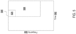
- a block diagram illustrates a resource region 505 comprised of a plurality of time 502 and frequency 504 resources, in accordance with various embodiments.
- the region 505 may be scheduled to be by transmitted to an eNB by a UE, such as an eNB 105-115 and/or a UE 150-160 of FIG. 1 .
- a sub-region 520 of the region 505 may be associated with power adaptation and/or randomization.
- An eNB may be adapted to schedule one or more UEs associated with power adaptation and/or randomization (e.g., cell-edge UEs, interference-limited UEs, etc.) on this sub-region 520.
- this sub-region 520 may include a control region 525, which may include control information, such as control information for one or more UEs associated with power adaptation and/or randomization (e.g., cell-edge UEs, interference-limited UEs, etc.).
- a plurality of eNBs may coordinate so that respective UEs served by each of the plurality of eNBs may be scheduled on a same sub-region 520.
- eNBs may schedule UEs associated with power adaptation and/or randomization (e.g., cell-edge UEs, interference-limited UEs, etc.) in a same sub-region 525.
- the plurality of eNBs may coordinate this sub-region 520 through slow coordination (e.g., through an X2 interface).
- the control region 525 may include information associated with coordination (e.g., cell coordination and/or UE coordination).
- the plurality of eNBs may coordinate so that all UEs in the sub-region 520 may be served only on QPSK.
- a flow diagram illustrates a method 600 for proactively requesting a power adaptation by a UE for IC, in accordance with various embodiments.
- the method 600 may be performed by a UE, such as the UE 150 of FIG. 1 . While FIG. 6 illustrates a plurality of sequential operations, one of ordinary skill would understand that one or more operations of the method 600 may be transposed and/or performed contemporaneously.
- the method 600 may include an operation 605 for receiving, by a UE, a downlink transmission.
- the downlink transmission may include a signal from an eNB.
- the downlink transmission may include noise that interferes with the intended signal.
- An operation 610 may include detecting for interference associated with reception of the downlink transmission.
- the operation 610 may include operations associated with measuring a signal power level and an interference power level. A difference between the measured signal power level and the measured interference power level may be compared to a predetermined threshold associated with IC at the UE. If the difference is greater than (or equal to, depending on the embodiment) the predetermined threshold then it may be inferred that the signal power level and the interference power level are sufficiently disparate for IC techniques to be applied.
- An operation 615 may comprise generating a request for an adjustment associated with transmission power by a transmitting node to facilitate interference cancellation by the UE.
- the request may be for an either an increase or a decrease in transmission power.
- the request may be generated to include an indication of a value for the increase or decrease. This value may be a specific value.
- the operation 615 may comprise an operation associated with computing a value (e.g., a dB value) that the difference between the signal power level and the interference power level must be increased in order for IC to be performed. This computed value may be included in the request.
- the request may include an indication of one or more increments or decrements that the transmitting node is to adjust its transmission power (e.g., an indication of value of a number of standard dB steps the transmitting node is to take up or down).
- the method 600 may include transmitting the generated request for the adjustment to an eNB.
- the request may be transmitted to an eNB that is transmitting the intended signal.
- the request may be transmitted to another eNB (e.g., an eNB that is not serving the UE), such as a neighboring eNB that is transmitting noise interfering with the signal.
- the request may be transmitted through a common uplink channel that is associated with requests for transmission power adjustments.
- IC may be performed because the difference between the signal power level and the interference power level may be greater than before.
- an indication of an adjusted transmission power by the transmitting node may be received. This indication may be used to perform IC at the UE.
- FIG. 7 a flow diagram illustrates a method 700 for transmission power randomization to facilitate IC at a UE, in accordance with various embodiments.
- the method 700 may be performed by a UE, such as the UE 150 of FIG. 1 . While FIG. 7 illustrates a plurality of sequential operations, one of ordinary skill would understand that one or more operations of the method 700 may be transposed and/or performed contemporaneously.
- the method 700 may include an operation 705 for receiving, by a UE from an eNB, an indication of a transmission power associated with a first resource element.
- the indication of the transmission power may be a seed.
- the operation 705 may include operations associated with generating a sequence associated with transmission power of one or more downlink transmissions based on the seed. While the generated sequence may be random or pseudorandom, it may be generated based on the seed such that the random or pseudorandom sequence is known or available to both the UE and the eNB that is to transmit a signal.
- the operation 705 may further include receiving a fluctuation range.
- the fluctuation range may be received separately from the indication of the transmission power or may be included therein.
- the fluctuation range may be implicitly embedded in the sequence generated from the seed.
- the fluctuation range may indicate a range that the power level of the intended signal may fluctuate (e.g., [-3 dB, +3 dB]) and may be influenced by channel and/or interference conditions.
- the method 700 may further include an operation 710 for receiving a downlink transmission comprised of the first resource element.
- the downlink transmission may include a signal from an eNB.
- the downlink transmission may include noise that interferes with the intended signal.
- an operation 715 may include performing IC on the downlink transmission based on the indication of the transmission power. Accordingly, the intended signal may be detected regardless of interference in the downlink transmission.
- a first transmission power level associated with the intended signal at the first resource element may be identified (e.g., based on a first element of the generated sequence). Therefore, interference having a power level disparate from the first transmission power level may be canceled.
- the downlink transmission may further include a second resource element associated with the intended signal.
- the second resource element may be associated with a second transmission power level that is different from the first transmission power level. Similar to the first transmission power level, the second transmission power level may be identified, for example, based on a second element of the generated sequence). Interference having a power level disparate from the second transmission power level may be canceled.
- the different transmission power levels associated with different resource elements may facilitate IC for detection of the intended signal, for example, by effecting an appreciable difference between the signal power level and the interference power level.
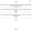
- FIG. 8 a flow diagram illustrates a method 800 for adjusting a transmission power level in response to a request from a UE, in accordance with various embodiments.
- the method 800 may be performed by an eNB, such as one of the eNBs 105-115 of FIG. 1 . While FIG. 8 illustrates a plurality of sequential operations, one of ordinary skill would understand that one or more operations of the method 800 may be transposed and/or performed contemporaneously.
- the method 800 may include an operation 805 for receiving, by an eNB, a request to adjust transmission power associated with downlink transmissions.
- this request may be received from a UE that may operate on a cell provided by the eNB.
- the request may be received from a UE that is not served by the eNB (e.g., an UE that may operate on a neighboring cell).
- the request may be received through a common uplink channel that is associated with requests for transmission power adjustments.
- An operation 810 may include adjusting the transmission power associated with downlink transmissions based on the request.
- the request may be for an either an increase or a decrease in transmission power.
- the request may include an indication of a value for the increase or decrease. This value may be a specific value.
- the operation 810 may comprise an operation associated with adjusting a downlink transmission power level by a value (e.g., a dB value) included in the request.
- the request may include an indication of one or more increments or decrements that the transmission power level is to be adjusted its (e.g., an indication of value of a number of standard dB steps the transmitting node is to take up or down).
- the operation 810 may include operations associated with computing an adjusted power level based on the request.
- the operation 810 may include computing an adjusted power level based on a predetermined algorithm that considers the request. Therefore, operation 810 may include adjusting the transmission power level, but not necessarily by an exact value indicated in the request.
- An operation 815 may include controlling transmitter circuitry to transmit a signal according to the adjusted transmission power.
- the transmitter circuitry may be remotely located from the eNB, such as at an RRH.
- FIG. 9 a flow diagram illustrates a method 900 for adjusting the transmission power of a plurality of resource elements associated with a downlink transmission, in accordance with various embodiments.
- the method 900 may be performed by an eNB, such as one of the eNBs 105-115 of FIG. 1 . While FIG. 9 illustrates a plurality of sequential operations, one of ordinary skill would understand that one or more operations of the method 900 may be transposed and/or performed contemporaneously.
- the method 900 may include an operation 905 for determining, by an eNB, a first transmission power associated with a first resource element.
- the operation 905 may include operations associated with generating a sequence associated with transmission power of one or more downlink transmissions based on a seed.
- the generated sequence may be random or pseudorandom.
- the sequence may be comprised of a plurality of values wherein a respective value is associated with the transmission power for a respective resource element.
- An operation 910 may include generating an indication of the first transmission power.
- the operation 910 may include operations associated with generating a message that includes the seed to be used for generation of the sequence.
- both the eNB and the UE may generate a same sequence associated with transmission powers of downlink transmissions.
- the operation 910 may further include determining a fluctuation range.
- the fluctuation range may be generated separately from the indication of the transmission power or may be included therein.
- the fluctuation range may be implicitly embedded in the sequence to be generated from the seed.
- the fluctuation range may indicate a range that the transmission power of a signal transmitted by the eNB may fluctuate (e.g., [-3 dB, +3 dB]) and may be influenced by channel and/or interference conditions.
- the method 900 may further include an operation 910 for transmitting an indication of the first transmission power to the UE to facilitate IC by the UE.
- the indication of the first transmission power may be the seed from which the UE is to generate the sequence.
- the operation 915 may further include transmitting an indication of the fluctuation range to the UE.
- An operation 920 may include controlling transmitter circuitry to transmit a signal having the first resource element according to the determined transmission power.
- the transmitter circuitry may be remotely located from the eNB, such as at an RRH.
- the operation 920 may include controlling transmitter circuitry to transmit a signal having a first transmission power level associated with the first resource element (e.g., based on a first element of the generated sequence).
- the downlink transmission may further include a second resource element associated with the transmitted signal.
- the second resource element may be associated with a second transmission power level that is different from the first transmission power level. Similar to the first transmission power level, the second transmission power level may be determined, for example, based on a second element of the generated sequence).
- the operation 920 may further include transmitting the signal having the second resource element according to the second transmission power level.
- the different transmission power levels associated with different resource elements may facilitate IC at the UE.
- FIG. 10 a block diagram illustrates an example computing device 1100, in accordance with various embodiments.
- One of the eNBs 105-115 and/or one of the UEs 150-160 of FIG. 1 and described herein may be implemented on a computing device such as computing device 1000. Further, the computing device 1100 may be adapted to perform one or more operations of the methods 600-900 described in FIGs. 6-9 , respectively.
- the computing device 1000 may include a number of components, one or more processors 1004, and one or more communication chips 1006. Depending upon the embodiment, one or more of the enumerated components may comprise "circuitry" of the computing device 1000, such as processing circuitry, communication circuitry, and the like.
- the one or more processor(s) 1004 each may be a processor core.
- the one or more communication chips 1006 may be physically and electrically coupled with the one or more processor(s) 1004.
- the communication chips 1006 may be part of the one or more processor(s) 1004.
- the computing device 1000 may include a printed circuit board ("PCB") 1002.
- PCB printed circuit board
- the one or more processor(s) 1004 and communication chip 1006 may be disposed thereon.
- the various components may be coupled without the employment of the PCB 1002.
- the computing device 1000 may include other components that may or may not be physically and electrically coupled with the PCB 1002.
- these other components include, but are not limited to, volatile memory (e.g., dynamic random access memory 1008, also referred to as "DRAM”), non-volatile memory (e.g., read only memory 1010, also referred to as "ROM”), flash memory 1012, an input/output controller 1014, a digital signal processor (not shown), a crypto processor (not shown), a graphics processor 1016, one or more antenna(s) 1018, a display (not shown), a touch screen display 1020, a touch screen controller 1022, a battery 1024, an audio codec (not shown), a video code (not shown), a global navigation satellite system 1028, a compass 1030, an accelerometer (not shown), a gyroscope (not shown), a speaker 1032, a camera 1034, one or more sensors 1036 (e.g., a barometer, Geiger counter,
- volatile memory e.g., DRAM 1008
- non-volatile memory e.g., ROM 1010
- flash memory 1012 e.g., NAND 1012
- mass storage device may include programming instructions configured to enable the computing device 1000, in response to the execution by one or more processor(s) 1004, to practice all or selected aspects of the data exchanges and methods described herein, depending on the embodiment of the computing device 1000 used to implement such data exchanges and methods.
- one or more of the memory components may include temporal and/or persistent copies of instructions that, when executed by one or more processor(s) 1004, enable the computing device 1000 to operate one or more modules 1038 configured to practice all or selected aspects of the data exchanges and method described herein, depending on the embodiment of the computing device 1000 used to implement such data exchanges and methods.
- the communication chips 1006 may enable wired and/or wireless communication for the transfer of data to and from the computing device 1000.
- wireless and its derivatives may be used to describe circuits, devices, systems, methods, techniques, communication channels, etc., that may communicate data through the use of modulated electromagnetic radiation through a non-solid medium. The term does not imply that the associated devices do not contain any wires, although in some embodiments they might not.
- the communication chips 1006 may implement any of a number of wireless standards or protocols, including but not limited to LTE, LTE-A, Institute of Electrical and Electronics Engineers (“IEEE”) 702.20, General Packet Radio Service (“GPRS”), Evolution Data Optimized (“Ev-DO”), Evolved High Speed Packet Access (“HSPA+”), Evolved High Speed Downlink Packet Access (“HSDPA+”), Evolved High Speed Uplink Packet Access (“HSUPA+”), Global System for Mobile Communications (“GSM”), Enhanced Data Rates for GSM Evolution (“EDGE”), Code Division Multiple Access (“CDMA”), Time Division Multiple Access (“TDMA”), Digital Enhanced Cordless Telecommunications (“DECT”), Bluetooth, derivatives thereof, as well as other wireless protocols that are designated as 3G, 4G, 5G, and beyond.
- LTE Long Term Evolution
- LTE-A Long Term Evolution
- IEEE Institute of Electrical and Electronics Engineers
- GPRS General Packet Radio Service
- Ev-DO Evolution
- the computing device 1000 may include a plurality of communication chips 1006 adapted to perform different communication functions.
- a first communication chip 1006 may be dedicated to shorter range wireless communications, such as Wi-Fi and Bluetooth
- a second communication chip 1006 may be dedicated to longer range wireless communications, such as GPS, EDGE, GPRS, CDMA, WiMAX, LTE, LTE-A, Ev-DO, and the like.
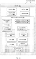
- FIG. 11 illustrates a device 1100 in accordance with some embodiments.
- the device 1100 may be similar to and/or included in one of the eNBs 105-115 and/or one of the UEs 150-160 of FIG. 1 .
- the device 1100 may include processing circuitry 1102, transmitter circuitry 1105, receiver circuitry 1110, communications circuitry 1115, and one or more antennas 1120 coupled with each other at least as shown.
- the communications circuitry 1115 may be coupled with the antennas 1120 to facilitate over-the-air communication of signals to/from the device 1100.
- Operations of the communications circuitry 1115 may include, but are not limited to, filtering, amplifying, storing, modulating, demodulating, transforming, etc.
- the transmitter circuitry 1105 may be coupled with the communications circuitry 1115 and may be configured to provide signals to the communications circuitry 1115 for transmission by the antennas 1120. In various embodiments, the transmitter circuitry 1105 may be configured to provide various signal processing operations on the signal to provide the signal to the communications circuitry 1115 with appropriate characteristics. In some embodiments, the transmitter circuitry 1105 may be adapted to generate signals. Further, the transmitter circuitry 1105 may be adapted to scramble, multiplex, and/or modulate various signals prior to transmission by the communications circuitry 1115.
- the receiver circuitry 1110 may be coupled with the communications circuitry 1115 and may be configured to receive signals from the communications circuitry 1115. In some embodiments, the receiver circuitry 1110 may be adapted to generate signals. Further, the receiver circuitry 1110 may be adapted to descramble, de-multiplex, and/or demodulate various signals following reception by the communications circuitry 1115.
- the processing circuitry 1102 may be coupled with the transmitter circuitry 1105, the receiver circuitry 1110, and/or the communications circuitry 1115.
- the processing circuitry may be adapted to perform operations described herein with respect to an eNB and/or a UE.
- the processing circuitry 1102 may be adapted to generate, process, and/or manipulate data that is to be transmitted over the air, e.g., to and/or from an eNB and/or a UE.
- the processing circuitry 1102 may be adapted to perform operations associated with adjusting transmission power levels.
- communications circuitry 1115, transmitter circuitry 1105, and/or receiver circuitry 1110 may be included in, for example, a communication chip and/or communicatively coupled with a printed circuit board as described with respect to FIG. 10 .
- Embodiments of the invention also relate to an apparatus for performing the operations herein.
- a computer program is stored in a non-transitory computer-readable medium.
- a machine-readable medium includes any mechanism for storing information in a form readable by a machine (e.g., a computer).
- a machine-readable (e.g., computer-readable) medium includes a machine- (e.g., a computer-) readable storage medium (e.g., read only memory (“ROM”), random access memory (“RAM”), magnetic disk storage media, optical storage media, flash memory devices).
- processing logic that comprises hardware (e.g., circuitry, dedicated logic, etc.), software (e.g., embodied on a non-transitory computer-readable medium), or a combination of both.
- processing logic comprises hardware (e.g., circuitry, dedicated logic, etc.), software (e.g., embodied on a non-transitory computer-readable medium), or a combination of both.
- Embodiments of the present invention are not described with reference to any particular programming language. It will be appreciated that a variety of programming languages can be used to implement the teachings of embodiments of the invention as described herein.
- embodiments of the invention have been described with reference to specific exemplary embodiments thereof. It will be evident that various modifications can be made thereto without departing from the broader scope of the invention as set forth in the following claims.
- the Specification and drawings are, accordingly, to be regarded in an illustrative sense rather than a restrictive sense.
Landscapes
- Engineering & Computer Science (AREA)
- Computer Networks & Wireless Communication (AREA)
- Signal Processing (AREA)
- Quality & Reliability (AREA)
- Mobile Radio Communication Systems (AREA)
Claims (9)
- Einrichtung (1100) zur Aufnahme in eine evolved Node B, "eNB", die Einrichtung (1100) umfassend: eine Verarbeitungsschaltung (1102), die dazu ausgelegt ist, eine erste Übertragungsleistung in Verbindung mit einem ersten Ressourcenelement zu bestimmen, die ferner dazu ausgelegt ist, eine Angabe der ersten Übertragungsleistung zu erzeugen, und die ferner dazu ausgelegt ist, die Übertragung eines Signals zu einer Benutzerausrüstung, "UE", zu steuern, die das erste Ressourcenelement in Verbindung mit der ersten Übertragungsleistung einschließt; und eine Senderschaltung (1105), die mit der Verarbeitungsschaltung (1102) gekoppelt und dazu ausgelegt ist, eine Angabe der ersten Übertragungsleistung zu der UE zur Interferenzunterdrückung durch die UE zu übertragen; dadurch gekennzeichnet, dass
die Verarbeitungsschaltung (1102) ferner dazu ausgelegt ist, einen Schwankungsbereich, in Dezibel, in Verbindung mit dem Signal zu bestimmen, und wobei ferner die Senderschaltung (1105) ferner dazu ausgelegt ist, eine Angabe des Schwankungsbereichs zu der UE zu übertragen. - Einrichtung nach Anspruch 1, wobei die Verarbeitungsschaltung ferner dazu ausgelegt ist, zu erfassen, dass sich die UE in der Nähe eines Zellrands befindet und dazu ausgelegt ist, die UE auf einem Bereich eines Ressourcenelements, einschließlich des ersten Ressourcenelements, in Verbindung mit Zellrand-UEs basierend auf der Erfassung zu planen, und wobei ferner die Verarbeitungsschaltung dazu ausgelegt ist, Übertragungsleistungen in Verbindung mit Ressourcenelementen des Bereichs basierend auf einer Pseudozufallssequenz zu steuern, und die Verarbeitungsschaltung wahlweise dazu ausgelegt ist, die erste Übertragungsleistung in Verbindung mit dem ersten Ressourcenelement mit einer anderen eNB zu koordinieren.
- Benutzerausrüstungsschaltung, "UE"-Schaltung, umfassend:eine Empfängerschaltung (1110), die dazu ausgelegt ist, von einer evolved Node B, "eNB", eine Angabe einer Übertragungsleistung in Verbindung mit einem ersten Ressourcenelement zu empfangen, und dazu ausgelegt ist, eine Downlink-Übertragung bestehend aus dem ersten Ressourcenelement zu empfangen;eine Verarbeitungsschaltung (1102), die dazu ausgelegt ist, eine Interferenzunterdrückung bei der Downlink-Übertragung basierend auf der Angabe der Übertragungsleistung zur Erfassung eines beabsichtigten Signals in Verbindung mit dem ersten Ressourcenelement durchzuführen; dadurch gekennzeichnet, dassdie Verarbeitungsschaltung (1102) ferner dazu ausgelegt ist, die Interferenzunterdrückung bei der Downlink-Übertragung ferner basierend auf einem Schwankungsbereich, in Dezibel, in Verbindung mit einer Übertragungsleistung der Downlink-Übertragung durchzuführen, wobei die Empfängerschaltung (1110) ferner dazu ausgelegt ist, eine Angabe des Schwankungsbereichs von der eNB zu empfangen.
- UE-Schaltung nach Anspruch 3, wobei die Angabe der Übertragungsleistung ein Startwert ist und die Verarbeitungsschaltung dazu ausgelegt ist, eine Sequenz in Verbindung mit der Übertragungsleistung der Downlink-Übertragung basierend auf dem Startwert zu erzeugen, und wobei ferner die Verarbeitungsschaltung dazu ausgelegt ist, die Interferenzunterdrückung bei der Downlink-Übertragung basierend auf der erzeugten Sequenz durchzuführen.
- UE-Schaltung nach Anspruch 4, wobei die Downlink-Übertragung aus dem ersten Ressourcenelement in Verbindung mit einer ersten Übertragungsleistung und einem zweiten Ressourcenelement in Verbindung mit einer zweiten Übertragungsleistung besteht, und wobei ferner die Verarbeitungsschaltung dazu ausgelegt ist, die Interferenzunterdrückung bei der Downlink-Übertragung basierend auf der erzeugten Sequenz zur Erfassung des beabsichtigten Signals in Verbindung mit dem ersten Ressourcenelement in Verbindung mit der ersten Übertragungsleistung und dem zweiten Ressourcenelement in Verbindung mit der zweiten Übertragungsleistung durchzuführen.
- Computerimplementiertes Verfahren (700), umfassend:Empfangen (705), von einer evolved Node B, "eNB", einer Angabe einer Übertragungsleistung in Verbindung mit einem ersten Ressourcenelement;Empfangen (710) einer Downlink-Übertragung bestehend aus dem ersten Ressourcenelement; undDurchführen (715) einer Interferenzunterdrückung bei der Downlink-Übertragung basierend auf der Angabe der Übertragungsleistung zur Erfassung eines beabsichtigten Signals in Verbindung mit dem ersten Ressourcenelement;dadurch gekennzeichnet, dass das Empfangen (705) der Angabe ein Empfangen eines Schwankungsbereichs, in Dezibel, von der eNB einschließt, und das Durchführen (715) der Interferenzunterdrückung bei der Downlink-Übertragung ferner auf dem Schwankungsbereich in Verbindung mit der Übertragungsleistung der Downlink-Übertragung basiert.
- Computerimplementiertes Verfahren (700) nach Anspruch 6, ferner umfassend ein Erzeugen einer Sequenz in Verbindung mit einer Übertragungsleistung der Downlink-Übertragung basierend auf dem Startwert, wobei die Sequenz zur Durchführung der Interferenzunterdrückung zu verwenden ist.
- Nicht-flüchtige rechenvorrichtungslesbare Medien, umfassend rechenvorrichtungsausführbare Befehle, wobei die Befehle, als Reaktion auf eine Ausführung durch eine Benutzerausrüstung, "UE", die UE veranlassen zum:Empfangen (705), von einer evolved Node B, "eNB", einer Angabe einer Übertragungsleistung in Verbindung mit einem ersten Ressourcenelement;Empfangen (710) einer Downlink-Übertragung bestehend aus dem ersten Ressourcenelement; undDurchführen (715) einer Interferenzunterdrückung bei der Downlink-Übertragung basierend auf der Angabe der Übertragungsleistung zur Erfassung eines beabsichtigten Signals in Verbindung mit dem ersten Ressourcenelement; dadurch gekennzeichnet, dass die Durchführung der Interferenzunterdrückung bei der Downlink-Übertragung ferner auf einem Schwankungsbereich, in Dezibel, in Verbindung mit einer Übertragungsleistung der Downlink-Übertragung basiert.
- Nicht-flüchtige rechenvorrichtungslesbare Medien nach Anspruch 8, wobei die Angabe der Übertragungsleistung ein Startwert ist und die Befehle die UE ferner veranlassen sollen zum:
Erzeugen einer Sequenz in Verbindung mit einer Übertragungsleistung der Downlink-Übertragung basierend auf dem Startwert, wobei die Sequenz zur Durchführung der Interferenzunterdrückung zu verwenden ist.
Applications Claiming Priority (2)
| Application Number | Priority Date | Filing Date | Title |
|---|---|---|---|
| US14/495,738 US20160088573A1 (en) | 2014-09-24 | 2014-09-24 | Power adaption and randomization for interference cancelation and mitigation |
| PCT/US2015/042058 WO2016048443A1 (en) | 2014-09-24 | 2015-07-24 | Power adaption and randomization for interference cancelation and mitigation |
Publications (2)
| Publication Number | Publication Date |
|---|---|
| EP3198952A1 EP3198952A1 (de) | 2017-08-02 |
| EP3198952B1 true EP3198952B1 (de) | 2019-11-13 |
Family
ID=53872149
Family Applications (1)
| Application Number | Title | Priority Date | Filing Date |
|---|---|---|---|
| EP15750862.3A Active EP3198952B1 (de) | 2014-09-24 | 2015-07-24 | Leistungsadaption und -randomisierung interferenzunterdrückung und -minderung |
Country Status (5)
| Country | Link |
|---|---|
| US (1) | US20160088573A1 (de) |
| EP (1) | EP3198952B1 (de) |
| KR (1) | KR20170038849A (de) |
| CN (1) | CN106664662B (de) |
| WO (1) | WO2016048443A1 (de) |
Families Citing this family (4)
| Publication number | Priority date | Publication date | Assignee | Title |
|---|---|---|---|---|
| US10432367B2 (en) * | 2015-02-23 | 2019-10-01 | Lg Electronics Inc. | Link adaptation method in wireless communication system employing inter-cell interference randomization technique |
| US11064442B1 (en) * | 2020-01-21 | 2021-07-13 | Sprint Communications Company L.P. | Uplink channel power management in dual connectivity devices |
| WO2023014123A1 (ko) * | 2021-08-06 | 2023-02-09 | 엘지전자 주식회사 | 무선 통신 시스템에서 하향링크 파워 조정 방법 및 장치 |
| US12289690B2 (en) * | 2022-06-09 | 2025-04-29 | Microsoft Technology Licensing, Llc | Interference reduction for wireless communications using interference cancellation and selective power control |
Family Cites Families (11)
| Publication number | Priority date | Publication date | Assignee | Title |
|---|---|---|---|---|
| CN1327723C (zh) * | 2000-05-01 | 2007-07-18 | 交互数字技术公司 | 时分双工通信系统中多下行链路时隙的下行链路功率控制 |
| ATE322769T1 (de) * | 2002-09-23 | 2006-04-15 | Verfahren und anordnung zur leistungsregelung in einem mobilen funksystem | |
| KR100696208B1 (ko) * | 2004-12-08 | 2007-03-20 | 한국전자통신연구원 | 다중 안테나 송수신 시스템의 제어 방법, 송신기 및 수신기 |
| CN100596130C (zh) * | 2006-09-06 | 2010-03-24 | 华为技术有限公司 | 一种载波干扰噪声比的测量方法及装置 |
| US8054776B2 (en) * | 2007-11-16 | 2011-11-08 | Mitsubishi Electric Research Laboratories, Inc. | Multiple power-multiple access in wireless networks for interference cancellation |
| US9801188B2 (en) * | 2008-02-01 | 2017-10-24 | Qualcomm Incorporated | Backhaul signaling for interference avoidance |
| CN101562466B (zh) * | 2008-04-15 | 2013-05-08 | 中兴通讯股份有限公司 | 一种提高反向数据速率的系统及方法 |
| CN102754479B (zh) * | 2010-02-11 | 2016-03-23 | 诺基亚技术有限公司 | 在通信系统中分配通信资源的装置和方法 |
| EP2666330A4 (de) * | 2011-01-21 | 2014-08-13 | Research In Motion Ltd | Bereitstellung von mobilgerätegeeführter downlink-interferenzverwaltung |
| ES2410680B1 (es) * | 2011-08-22 | 2014-07-30 | Telefónica, S.A. | Método para facilitar la minimización de interferencia intercelular aprovechando sus características conocidas |
| US8781427B1 (en) * | 2013-03-11 | 2014-07-15 | Rafael Microelectronics, Inc. | Signal receiving circuit and the related signal receiving method |
-
2014
- 2014-09-24 US US14/495,738 patent/US20160088573A1/en not_active Abandoned
-
2015
- 2015-07-24 WO PCT/US2015/042058 patent/WO2016048443A1/en not_active Ceased
- 2015-07-24 CN CN201580043864.4A patent/CN106664662B/zh not_active Expired - Fee Related
- 2015-07-24 KR KR1020177004836A patent/KR20170038849A/ko not_active Abandoned
- 2015-07-24 EP EP15750862.3A patent/EP3198952B1/de active Active
Non-Patent Citations (1)
| Title |
|---|
| None * |
Also Published As
| Publication number | Publication date |
|---|---|
| CN106664662A (zh) | 2017-05-10 |
| CN106664662B (zh) | 2020-12-25 |
| US20160088573A1 (en) | 2016-03-24 |
| WO2016048443A1 (en) | 2016-03-31 |
| KR20170038849A (ko) | 2017-04-07 |
| EP3198952A1 (de) | 2017-08-02 |
Similar Documents
| Publication | Publication Date | Title |
|---|---|---|
| US10103797B2 (en) | Quasi co-location and PDSCH resource element mapping signaling for network assisted interference mitigation | |
| US9819470B2 (en) | Method and arrangement for interference mitigation | |
| CA2861484C (en) | Uplink coordinated multi-point | |
| US20180242327A1 (en) | Systems And Methods Of Reducing Interference In A Wireless Communications System | |
| EP3100561B1 (de) | Verfahren zur interferentendetektierung für interferenzreduzierung | |
| EP3375106B1 (de) | Meldung von kanalstationsinformationen und übertragungsmodus für verbesserte maschinenkommunikation | |
| EP3185446A1 (de) | Interferenzmittelwertbildung und interferenzressourcengruppen in einem drahtloskommunikationssystem | |
| EP3086495B1 (de) | Übertragungsverfahren für overhead-informationen, basisstation und endgerät. | |
| EP3157306B1 (de) | Basisstationsvorrichtung, endgerätevorrichtung und kommunikationsverfahren | |
| US9578653B2 (en) | Network assisted parameter estimation in the presence of inter-cell interference | |
| CN109150337B (zh) | 一种干扰功率测量方法及设备 | |
| EP3179764A1 (de) | Basisstationsvorrichtung, endgerätevorrichtung und verfahren | |
| EP2958250A1 (de) | Kanalschätzung mit vorcodierender matrixglättung am sender | |
| US10447320B2 (en) | Terminal apparatus, base station apparatus, and communication method | |
| EP3198952B1 (de) | Leistungsadaption und -randomisierung interferenzunterdrückung und -minderung | |
| US10200959B2 (en) | Methods, systems, and computer program products for calibrating amplitude hardware-induced distortion in a long term evolution (LTE) communications system | |
| US9854490B2 (en) | Rank indicator inheritance for subframe restricted channel state information reporting | |
| HK1235960A1 (en) | Power adaption and randomization for interference cancelation and mitigation |
Legal Events
| Date | Code | Title | Description |
|---|---|---|---|
| STAA | Information on the status of an ep patent application or granted ep patent |
Free format text: STATUS: THE INTERNATIONAL PUBLICATION HAS BEEN MADE |
|
| PUAI | Public reference made under article 153(3) epc to a published international application that has entered the european phase |
Free format text: ORIGINAL CODE: 0009012 |
|
| STAA | Information on the status of an ep patent application or granted ep patent |
Free format text: STATUS: REQUEST FOR EXAMINATION WAS MADE |
|
| 17P | Request for examination filed |
Effective date: 20170213 |
|
| AK | Designated contracting states |
Kind code of ref document: A1 Designated state(s): AL AT BE BG CH CY CZ DE DK EE ES FI FR GB GR HR HU IE IS IT LI LT LU LV MC MK MT NL NO PL PT RO RS SE SI SK SM TR |
|
| AX | Request for extension of the european patent |
Extension state: BA ME |
|
| DAV | Request for validation of the european patent (deleted) | ||
| DAX | Request for extension of the european patent (deleted) | ||
| STAA | Information on the status of an ep patent application or granted ep patent |
Free format text: STATUS: EXAMINATION IS IN PROGRESS |
|
| 17Q | First examination report despatched |
Effective date: 20180129 |
|
| GRAP | Despatch of communication of intention to grant a patent |
Free format text: ORIGINAL CODE: EPIDOSNIGR1 |
|
| STAA | Information on the status of an ep patent application or granted ep patent |
Free format text: STATUS: GRANT OF PATENT IS INTENDED |
|
| INTG | Intention to grant announced |
Effective date: 20190621 |
|
| GRAS | Grant fee paid |
Free format text: ORIGINAL CODE: EPIDOSNIGR3 |
|
| GRAA | (expected) grant |
Free format text: ORIGINAL CODE: 0009210 |
|
| STAA | Information on the status of an ep patent application or granted ep patent |
Free format text: STATUS: THE PATENT HAS BEEN GRANTED |
|
| AK | Designated contracting states |
Kind code of ref document: B1 Designated state(s): AL AT BE BG CH CY CZ DE DK EE ES FI FR GB GR HR HU IE IS IT LI LT LU LV MC MK MT NL NO PL PT RO RS SE SI SK SM TR |
|
| REG | Reference to a national code |
Ref country code: CH Ref legal event code: EP Ref country code: AT Ref legal event code: REF Ref document number: 1203025 Country of ref document: AT Kind code of ref document: T Effective date: 20191115 |
|
| REG | Reference to a national code |
Ref country code: DE Ref legal event code: R096 Ref document number: 602015041667 Country of ref document: DE |
|
| REG | Reference to a national code |
Ref country code: IE Ref legal event code: FG4D |
|
| REG | Reference to a national code |
Ref country code: NL Ref legal event code: MP Effective date: 20191113 |
|
| REG | Reference to a national code |
Ref country code: LT Ref legal event code: MG4D |
|
| PG25 | Lapsed in a contracting state [announced via postgrant information from national office to epo] |
Ref country code: SE Free format text: LAPSE BECAUSE OF FAILURE TO SUBMIT A TRANSLATION OF THE DESCRIPTION OR TO PAY THE FEE WITHIN THE PRESCRIBED TIME-LIMIT Effective date: 20191113 Ref country code: LV Free format text: LAPSE BECAUSE OF FAILURE TO SUBMIT A TRANSLATION OF THE DESCRIPTION OR TO PAY THE FEE WITHIN THE PRESCRIBED TIME-LIMIT Effective date: 20191113 Ref country code: PL Free format text: LAPSE BECAUSE OF FAILURE TO SUBMIT A TRANSLATION OF THE DESCRIPTION OR TO PAY THE FEE WITHIN THE PRESCRIBED TIME-LIMIT Effective date: 20191113 Ref country code: PT Free format text: LAPSE BECAUSE OF FAILURE TO SUBMIT A TRANSLATION OF THE DESCRIPTION OR TO PAY THE FEE WITHIN THE PRESCRIBED TIME-LIMIT Effective date: 20200313 Ref country code: NO Free format text: LAPSE BECAUSE OF FAILURE TO SUBMIT A TRANSLATION OF THE DESCRIPTION OR TO PAY THE FEE WITHIN THE PRESCRIBED TIME-LIMIT Effective date: 20200213 Ref country code: GR Free format text: LAPSE BECAUSE OF FAILURE TO SUBMIT A TRANSLATION OF THE DESCRIPTION OR TO PAY THE FEE WITHIN THE PRESCRIBED TIME-LIMIT Effective date: 20200214 Ref country code: LT Free format text: LAPSE BECAUSE OF FAILURE TO SUBMIT A TRANSLATION OF THE DESCRIPTION OR TO PAY THE FEE WITHIN THE PRESCRIBED TIME-LIMIT Effective date: 20191113 Ref country code: FI Free format text: LAPSE BECAUSE OF FAILURE TO SUBMIT A TRANSLATION OF THE DESCRIPTION OR TO PAY THE FEE WITHIN THE PRESCRIBED TIME-LIMIT Effective date: 20191113 Ref country code: BG Free format text: LAPSE BECAUSE OF FAILURE TO SUBMIT A TRANSLATION OF THE DESCRIPTION OR TO PAY THE FEE WITHIN THE PRESCRIBED TIME-LIMIT Effective date: 20200213 Ref country code: NL Free format text: LAPSE BECAUSE OF FAILURE TO SUBMIT A TRANSLATION OF THE DESCRIPTION OR TO PAY THE FEE WITHIN THE PRESCRIBED TIME-LIMIT Effective date: 20191113 |
|
| PG25 | Lapsed in a contracting state [announced via postgrant information from national office to epo] |
Ref country code: RS Free format text: LAPSE BECAUSE OF FAILURE TO SUBMIT A TRANSLATION OF THE DESCRIPTION OR TO PAY THE FEE WITHIN THE PRESCRIBED TIME-LIMIT Effective date: 20191113 Ref country code: IS Free format text: LAPSE BECAUSE OF FAILURE TO SUBMIT A TRANSLATION OF THE DESCRIPTION OR TO PAY THE FEE WITHIN THE PRESCRIBED TIME-LIMIT Effective date: 20200313 Ref country code: HR Free format text: LAPSE BECAUSE OF FAILURE TO SUBMIT A TRANSLATION OF THE DESCRIPTION OR TO PAY THE FEE WITHIN THE PRESCRIBED TIME-LIMIT Effective date: 20191113 |
|
| REG | Reference to a national code |
Ref country code: DE Ref legal event code: R081 Ref document number: 602015041667 Country of ref document: DE Owner name: APPLE INC., CUPERTINO, US Free format text: FORMER OWNER: INTEL CORP., SANTA CLARA, CALIF., US |
|
| PG25 | Lapsed in a contracting state [announced via postgrant information from national office to epo] |
Ref country code: AL Free format text: LAPSE BECAUSE OF FAILURE TO SUBMIT A TRANSLATION OF THE DESCRIPTION OR TO PAY THE FEE WITHIN THE PRESCRIBED TIME-LIMIT Effective date: 20191113 |
|
| PG25 | Lapsed in a contracting state [announced via postgrant information from national office to epo] |
Ref country code: RO Free format text: LAPSE BECAUSE OF FAILURE TO SUBMIT A TRANSLATION OF THE DESCRIPTION OR TO PAY THE FEE WITHIN THE PRESCRIBED TIME-LIMIT Effective date: 20191113 Ref country code: EE Free format text: LAPSE BECAUSE OF FAILURE TO SUBMIT A TRANSLATION OF THE DESCRIPTION OR TO PAY THE FEE WITHIN THE PRESCRIBED TIME-LIMIT Effective date: 20191113 Ref country code: DK Free format text: LAPSE BECAUSE OF FAILURE TO SUBMIT A TRANSLATION OF THE DESCRIPTION OR TO PAY THE FEE WITHIN THE PRESCRIBED TIME-LIMIT Effective date: 20191113 Ref country code: ES Free format text: LAPSE BECAUSE OF FAILURE TO SUBMIT A TRANSLATION OF THE DESCRIPTION OR TO PAY THE FEE WITHIN THE PRESCRIBED TIME-LIMIT Effective date: 20191113 Ref country code: CZ Free format text: LAPSE BECAUSE OF FAILURE TO SUBMIT A TRANSLATION OF THE DESCRIPTION OR TO PAY THE FEE WITHIN THE PRESCRIBED TIME-LIMIT Effective date: 20191113 |
|
| REG | Reference to a national code |
Ref country code: DE Ref legal event code: R097 Ref document number: 602015041667 Country of ref document: DE |
|
| REG | Reference to a national code |
Ref country code: AT Ref legal event code: MK05 Ref document number: 1203025 Country of ref document: AT Kind code of ref document: T Effective date: 20191113 |
|
| PG25 | Lapsed in a contracting state [announced via postgrant information from national office to epo] |
Ref country code: SM Free format text: LAPSE BECAUSE OF FAILURE TO SUBMIT A TRANSLATION OF THE DESCRIPTION OR TO PAY THE FEE WITHIN THE PRESCRIBED TIME-LIMIT Effective date: 20191113 Ref country code: SK Free format text: LAPSE BECAUSE OF FAILURE TO SUBMIT A TRANSLATION OF THE DESCRIPTION OR TO PAY THE FEE WITHIN THE PRESCRIBED TIME-LIMIT Effective date: 20191113 |
|
| PLBE | No opposition filed within time limit |
Free format text: ORIGINAL CODE: 0009261 |
|
| STAA | Information on the status of an ep patent application or granted ep patent |
Free format text: STATUS: NO OPPOSITION FILED WITHIN TIME LIMIT |
|
| 26N | No opposition filed |
Effective date: 20200814 |
|
| PGFP | Annual fee paid to national office [announced via postgrant information from national office to epo] |
Ref country code: DE Payment date: 20200714 Year of fee payment: 6 |
|
| PG25 | Lapsed in a contracting state [announced via postgrant information from national office to epo] |
Ref country code: SI Free format text: LAPSE BECAUSE OF FAILURE TO SUBMIT A TRANSLATION OF THE DESCRIPTION OR TO PAY THE FEE WITHIN THE PRESCRIBED TIME-LIMIT Effective date: 20191113 Ref country code: AT Free format text: LAPSE BECAUSE OF FAILURE TO SUBMIT A TRANSLATION OF THE DESCRIPTION OR TO PAY THE FEE WITHIN THE PRESCRIBED TIME-LIMIT Effective date: 20191113 |
|
| PG25 | Lapsed in a contracting state [announced via postgrant information from national office to epo] |
Ref country code: IT Free format text: LAPSE BECAUSE OF FAILURE TO SUBMIT A TRANSLATION OF THE DESCRIPTION OR TO PAY THE FEE WITHIN THE PRESCRIBED TIME-LIMIT Effective date: 20191113 |
|
| PG25 | Lapsed in a contracting state [announced via postgrant information from national office to epo] |
Ref country code: MC Free format text: LAPSE BECAUSE OF FAILURE TO SUBMIT A TRANSLATION OF THE DESCRIPTION OR TO PAY THE FEE WITHIN THE PRESCRIBED TIME-LIMIT Effective date: 20191113 |
|
| REG | Reference to a national code |
Ref country code: CH Ref legal event code: PL |
|
| GBPC | Gb: european patent ceased through non-payment of renewal fee |
Effective date: 20200724 |
|
| REG | Reference to a national code |
Ref country code: BE Ref legal event code: MM Effective date: 20200731 |
|
| PG25 | Lapsed in a contracting state [announced via postgrant information from national office to epo] |
Ref country code: FR Free format text: LAPSE BECAUSE OF NON-PAYMENT OF DUE FEES Effective date: 20200731 Ref country code: LI Free format text: LAPSE BECAUSE OF NON-PAYMENT OF DUE FEES Effective date: 20200731 Ref country code: LU Free format text: LAPSE BECAUSE OF NON-PAYMENT OF DUE FEES Effective date: 20200724 Ref country code: CH Free format text: LAPSE BECAUSE OF NON-PAYMENT OF DUE FEES Effective date: 20200731 Ref country code: GB Free format text: LAPSE BECAUSE OF NON-PAYMENT OF DUE FEES Effective date: 20200724 |
|
| PG25 | Lapsed in a contracting state [announced via postgrant information from national office to epo] |
Ref country code: BE Free format text: LAPSE BECAUSE OF NON-PAYMENT OF DUE FEES Effective date: 20200731 |
|
| PG25 | Lapsed in a contracting state [announced via postgrant information from national office to epo] |
Ref country code: IE Free format text: LAPSE BECAUSE OF NON-PAYMENT OF DUE FEES Effective date: 20200724 |
|
| REG | Reference to a national code |
Ref country code: DE Ref legal event code: R119 Ref document number: 602015041667 Country of ref document: DE |
|
| PG25 | Lapsed in a contracting state [announced via postgrant information from national office to epo] |
Ref country code: DE Free format text: LAPSE BECAUSE OF NON-PAYMENT OF DUE FEES Effective date: 20220201 |
|
| PG25 | Lapsed in a contracting state [announced via postgrant information from national office to epo] |
Ref country code: TR Free format text: LAPSE BECAUSE OF FAILURE TO SUBMIT A TRANSLATION OF THE DESCRIPTION OR TO PAY THE FEE WITHIN THE PRESCRIBED TIME-LIMIT Effective date: 20191113 Ref country code: MT Free format text: LAPSE BECAUSE OF FAILURE TO SUBMIT A TRANSLATION OF THE DESCRIPTION OR TO PAY THE FEE WITHIN THE PRESCRIBED TIME-LIMIT Effective date: 20191113 Ref country code: CY Free format text: LAPSE BECAUSE OF FAILURE TO SUBMIT A TRANSLATION OF THE DESCRIPTION OR TO PAY THE FEE WITHIN THE PRESCRIBED TIME-LIMIT Effective date: 20191113 |
|
| PG25 | Lapsed in a contracting state [announced via postgrant information from national office to epo] |
Ref country code: MK Free format text: LAPSE BECAUSE OF FAILURE TO SUBMIT A TRANSLATION OF THE DESCRIPTION OR TO PAY THE FEE WITHIN THE PRESCRIBED TIME-LIMIT Effective date: 20191113 |