EP3198232B1 - Integrated shaft bearing for a sensor - Google Patents
Integrated shaft bearing for a sensor Download PDFInfo
- Publication number
- EP3198232B1 EP3198232B1 EP15770867.8A EP15770867A EP3198232B1 EP 3198232 B1 EP3198232 B1 EP 3198232B1 EP 15770867 A EP15770867 A EP 15770867A EP 3198232 B1 EP3198232 B1 EP 3198232B1
- Authority
- EP
- European Patent Office
- Prior art keywords
- housing part
- shaft
- sensor device
- sensor
- bearing portion
- Prior art date
- Legal status (The legal status is an assumption and is not a legal conclusion. Google has not performed a legal analysis and makes no representation as to the accuracy of the status listed.)
- Active
Links
- 239000000314 lubricant Substances 0.000 claims description 9
- 230000007704 transition Effects 0.000 description 5
- 239000000463 material Substances 0.000 description 3
- 240000006829 Ficus sundaica Species 0.000 description 2
- 239000006096 absorbing agent Substances 0.000 description 2
- 239000004020 conductor Substances 0.000 description 2
- 238000004519 manufacturing process Methods 0.000 description 2
- 239000002245 particle Substances 0.000 description 2
- 238000000926 separation method Methods 0.000 description 2
- 230000035939 shock Effects 0.000 description 2
- 239000000243 solution Substances 0.000 description 2
- XLYOFNOQVPJJNP-UHFFFAOYSA-N water Substances O XLYOFNOQVPJJNP-UHFFFAOYSA-N 0.000 description 2
- 238000006308 Hooker rearrangement reaction Methods 0.000 description 1
- 230000000295 complement effect Effects 0.000 description 1
- 230000001419 dependent effect Effects 0.000 description 1
- 230000000694 effects Effects 0.000 description 1
- 238000005538 encapsulation Methods 0.000 description 1
- 239000012530 fluid Substances 0.000 description 1
- 238000002347 injection Methods 0.000 description 1
- 239000007924 injection Substances 0.000 description 1
- 238000001746 injection moulding Methods 0.000 description 1
- 230000001050 lubricating effect Effects 0.000 description 1
- 230000035515 penetration Effects 0.000 description 1
- 230000002093 peripheral effect Effects 0.000 description 1
- 239000004810 polytetrafluoroethylene Substances 0.000 description 1
- 229920001343 polytetrafluoroethylene Polymers 0.000 description 1
- 239000000565 sealant Substances 0.000 description 1
- 239000007787 solid Substances 0.000 description 1
Images


Classifications
-
- G—PHYSICS
- G01—MEASURING; TESTING
- G01D—MEASURING NOT SPECIALLY ADAPTED FOR A SPECIFIC VARIABLE; ARRANGEMENTS FOR MEASURING TWO OR MORE VARIABLES NOT COVERED IN A SINGLE OTHER SUBCLASS; TARIFF METERING APPARATUS; MEASURING OR TESTING NOT OTHERWISE PROVIDED FOR
- G01D5/00—Mechanical means for transferring the output of a sensing member; Means for converting the output of a sensing member to another variable where the form or nature of the sensing member does not constrain the means for converting; Transducers not specially adapted for a specific variable
- G01D5/12—Mechanical means for transferring the output of a sensing member; Means for converting the output of a sensing member to another variable where the form or nature of the sensing member does not constrain the means for converting; Transducers not specially adapted for a specific variable using electric or magnetic means
-
- G—PHYSICS
- G01—MEASURING; TESTING
- G01C—MEASURING DISTANCES, LEVELS OR BEARINGS; SURVEYING; NAVIGATION; GYROSCOPIC INSTRUMENTS; PHOTOGRAMMETRY OR VIDEOGRAMMETRY
- G01C19/00—Gyroscopes; Turn-sensitive devices using vibrating masses; Turn-sensitive devices without moving masses; Measuring angular rate using gyroscopic effects
-
- G—PHYSICS
- G01—MEASURING; TESTING
- G01D—MEASURING NOT SPECIALLY ADAPTED FOR A SPECIFIC VARIABLE; ARRANGEMENTS FOR MEASURING TWO OR MORE VARIABLES NOT COVERED IN A SINGLE OTHER SUBCLASS; TARIFF METERING APPARATUS; MEASURING OR TESTING NOT OTHERWISE PROVIDED FOR
- G01D5/00—Mechanical means for transferring the output of a sensing member; Means for converting the output of a sensing member to another variable where the form or nature of the sensing member does not constrain the means for converting; Transducers not specially adapted for a specific variable
- G01D5/12—Mechanical means for transferring the output of a sensing member; Means for converting the output of a sensing member to another variable where the form or nature of the sensing member does not constrain the means for converting; Transducers not specially adapted for a specific variable using electric or magnetic means
- G01D5/14—Mechanical means for transferring the output of a sensing member; Means for converting the output of a sensing member to another variable where the form or nature of the sensing member does not constrain the means for converting; Transducers not specially adapted for a specific variable using electric or magnetic means influencing the magnitude of a current or voltage
- G01D5/142—Mechanical means for transferring the output of a sensing member; Means for converting the output of a sensing member to another variable where the form or nature of the sensing member does not constrain the means for converting; Transducers not specially adapted for a specific variable using electric or magnetic means influencing the magnitude of a current or voltage using Hall-effect devices
- G01D5/145—Mechanical means for transferring the output of a sensing member; Means for converting the output of a sensing member to another variable where the form or nature of the sensing member does not constrain the means for converting; Transducers not specially adapted for a specific variable using electric or magnetic means influencing the magnitude of a current or voltage using Hall-effect devices influenced by the relative movement between the Hall device and magnetic fields
-
- G—PHYSICS
- G01—MEASURING; TESTING
- G01D—MEASURING NOT SPECIALLY ADAPTED FOR A SPECIFIC VARIABLE; ARRANGEMENTS FOR MEASURING TWO OR MORE VARIABLES NOT COVERED IN A SINGLE OTHER SUBCLASS; TARIFF METERING APPARATUS; MEASURING OR TESTING NOT OTHERWISE PROVIDED FOR
- G01D11/00—Component parts of measuring arrangements not specially adapted for a specific variable
- G01D11/24—Housings ; Casings for instruments
- G01D11/245—Housings for sensors
Definitions
- the invention relates to a sensor device for detecting a rotation according to the preamble of the main claim.
- the height sensor shown in this document has a lever arm connected at a first end to a moving member. At the other end of the lever arm is connected to a shaft, wherein the shaft has a signal-generating element, so that via the movement of the shaft, the rotation of the lever arm can be determined.
- the shaft is mounted inside a housing.
- the shaft 14 has at its end facing away from the lever arm circumferentially on a rotationally symmetrical collar with a shoulder.
- the collar is located in a corresponding collar receiving area of the storage room whose diameter is larger than the diameter of the remaining storage space.
- the solution shown in this document has the disadvantage that the shaft can not be formed integrally with the lever member.
- the shaft for storing the same has a spherical cap portion.
- the spherical cap portion By means of the spherical cap portion, it is indeed possible to insert the shaft into the housing part and lock it in this.
- the tailor-made production of the spherical cap portion is relatively complex.
- the object of the invention is therefore to show a sensor device with a shaft element which can be produced easily, which can be installed with little effort in a housing of the sensor device.
- the invention is based on the basic idea of achieving a simple producibility of a radial and axial mounting of the shaft element of the position sensor by means of the section tapering towards the shaft end.
- the taper of the bearing portion can be realized by means of a continuously tapering or conically shaped portion. However, it is also conceivable to realize the taper gradually. The latter variant can be realized for example by means of a blind hole.
- the shaft element rests on the housing part in the region of the bearing section, so that the shaft element is supported on the one hand in the radial direction as well as in an axial direction.
- the arrangement of the tapered section on the second shaft end, where a magnetic element is arranged as a signal generator, has the advantage that this position-sensitive area is stored directly and thus remains positionally stable. As a result, sufficient positional fidelity of the shaft element can already be ensured with a bearing section.
- the shaft element can be further inserted from the outside or from above into the interior of the housing part, so that it is possible that Form shaft element integrally with the lever element and at the same time to install with a step within the housing part, with further adjustment steps thereof are not taken into account.
- This structure also simplifies the separation of the two sections of the housing part and thus also the separation of the sensor element from external influences that may be present within the first portion of the housing part.
- bearing portion is used in the context of the invention to describe a portion or region in which the shaft member or housing part are formed in accordance with the invention, in order to achieve a bearing of the shaft member on the housing part. Therefore, the bearing portions on the shaft member and the housing part are aligned with each other so that they are in contact with each other. Due to the direct contact between the housing part and the shaft element in the region of the bearing section, friction occurs between the two parts during a rotation of the shaft element. However, these frictions are acceptable to some extent for many applications. However, to avoid too high friction between the housing part and the shaft member is outside the bearing portion no contact between the two parts. Thus, there is an air gap between the shaft element and the housing part outside the bearing section. In this way, the bearing portions can also be aligned with each other in such a way to adjust the friction level or intensity by manufacturing measures or design measures in the desired.
- the housing part is designed as a separate part from the housing of the sensor device, which part can be connected to the housing by encapsulation or can be integrated into the housing.
- the housing part constitutes an area or section of an integrally formed housing.
- the first and second section of the housing Housing part according to the invention are so separated from each other, so that a flow of moisture through water, oil or similar media from one to the other section is not possible, for example.
- the sensor device according to the invention is characterized in an advantageous manner that the first bearing portion is formed stepwise tapered.
- the stepwise execution of the bearing section has the advantage of easy manufacturability.
- this embodiment has the advantage that the area towards the second shaft end can be sealed off by means of the contact surfaces between the shaft element and the housing part.
- the area between the magnetic element and the housing can be effectively protected in this way against dirt and moisture, which could possibly affect the effect of the sensor element.
- the stepwise design of the bearing portion allows the axial distance between the magnetic element and the sensor element set as accurately as possible.
- the sensor device according to the invention is characterized in an advantageous manner that the first bearing portion each having a substantially horizontal and a substantially vertically extending contact surface, which adjoin one another directly.
- the storage of the shaft member is particularly easy to reach.
- the sensor device according to the invention is further developed in an advantageous manner, that the housing part and the shaft member is made in the area of the first bearing portion accurately. Due to the accuracy of fit, a high positional fidelity and a good seal of the area of the second shaft end are achieved.
- the sensor device according to the invention is characterized in an advantageous manner that the position of the horizontal contact surfaces is made precisely. In this way, the axial distance between the magnetic element and the sensor element can be set particularly accurately. In this context, it should therefore be perfectly accurate that the tolerance range for producing or processing the affected area or section to other areas is significantly smaller in order to achieve greater accuracy of the dimensions and relative position.
- the sensor device according to the invention is characterized in an advantageous manner that the second shaft end is not in contact with the housing part. Although this increases the distance between the magnetic element and the sensor element. However, by a small clearance between the housing part and the second shaft end, the friction is avoided during rotation of the shaft member, which allows a total of a more fluid rotation of the shaft member.
- the sensor device is characterized in an advantageous manner that the housing part and the shaft member between the first shaft end and the first bearing portion each having a second bearing portion for the radial mounting of the shaft member.
- the shaft element is supported only by the two bearing sections and is also in contact with the housing part only in the region of the bearing sections.
- the further radial bearing on the second bearing portion effectively prevents the shaft element from tilting about the longitudinal axis. In this way, it is possible to keep the shaft element in a particularly positionally stable manner relative to the housing part and thus also to the sensor element.
- the shaft element and the housing part are advantageously designed to fit each other in the area of the second bearing section.
- Other radial bearing sections Although conceivable, but the combination of the first and second storage sections provides the ideal solution for cost-effective and safe storage of the shaft element.
- the sensor device according to the invention is further developed in an advantageous manner, that the shaft element in the second bearing portion is a projection formed with a substantially parallel to the longitudinal axis of the shaft member extending contact surface to the housing part. In this way, the storage on the second storage section is particularly easy to implement.
- the sensor device is characterized in an advantageous manner that the surface of the housing part or shaft member has a lubricant at least in the region of a bearing portion.
- the friction between the shaft member and the housing part can be effectively reduced.
- the sensor device is further developed in an advantageous manner that the housing part has in the region of at least one bearing portion segmentally shaped contact surfaces, wherein the contact surfaces are separated by grooves or recesses. Due to the segment-like or segment-shaped contact surfaces, the bearing of the shaft member is further ensured on the housing part. Overall, the size of the total contact surface is reduced by means of the free spaces between the contact surfaces. so that the friction between the shaft member and the housing part is reduced. Furthermore, the free spaces or grooves have the advantage that dirt particles or the like do not deposit in the area of the contact surfaces, but are conveyed into the grooves by rotation of the shaft element.
- the hookers disposed between the contact surfaces may also be used as reservoirs for lubricants.
- the sensor device according to the invention is characterized in an advantageous manner that the grooves or recesses are provided for receiving a lubricant.
- the bearing sections are provided with a lubricant before mounting the shaft member in the housing part. Through the grooves, a larger amount of lubricant can be introduced into the bearing sections.
- the sensor device according to the invention is further developed in an advantageous manner, that the fit in the region of the bearing portion is designed to seal the region of the second shaft end.
- the sensor device is characterized in an advantageous manner that the sensor element comprises a chip, wherein the housing part in the first portion has a recess for receiving the chip or an electronic component for detecting the magnetic field of the Magnetlements, wherein the position of the recess precisely to the position of the Shaft element is aligned. In this way, it is ensured that the sensor element also maintains the relative position to the magnetic element over the entire service life of the sensor device.
- the sensor device is characterized in an advantageous manner that the position sensor a Lever element which is arranged on the first shaft end and is integrally formed with the shaft member, wherein in the region between the shaft member and the lever element, a recess is formed, about which the position sensor can be latched into the housing part.
- the position sensor can be mounted particularly low effort.
- the engagement of the position sensor on the housing part in the connecting region between the lever element and the shaft element further has the advantage that the penetration of dirt and moisture into the housing part can be partially prevented. Depending on the application, this area can also be provided with an additional seal.
- the invention further includes the aspect of using the sensor device according to the invention as a height sensor.
- the aforementioned embodiments are particularly well suited for use in a level sensor, since the rotational speeds and rotational strokes are relatively low and thus a contact bearing between the shaft member and the housing part over a longer service life are preserved.
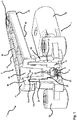
- FIG. 1 shows a sensor device 1 for detecting a rotation with a position sensor 2, a sensor element 5 and a housing 7 integrated in a housing part 70.
- the sensor device 1 is used as a height sensor, in particular for determining the height of a motor vehicle body.
- the sensor device 1 is connected to a height adjustment device of the motor vehicle, for example a shock absorber. If the height of the vehicle body is adjusted, the height of the adjustment by means of the sensor device 1 can be determined.
- the sensor device is exposed to dirt and water, as it is located in the area of the wheels. Therefore, it is necessary to protect the functionally essential parts of the sensor device 1 from external influences. This concerns in particular the electronics. In particular, with regard to the longevity, it is essential that the interior of the sensor device 1 remains substantially dry.
- the position sensor 2 has a shaft element 20 with a first and second shaft end 21, 22.
- the position sensor 2 further comprises a lever element 40, which is arranged on the first shaft end 21.
- the shaft member 20 and the lever member 40 are integrally formed.
- the lever member 40 and the shaft member 20 are preferably made as an injection molded part.
- the lever member 40 has a bore 41 (s. FIG. 2 ), over which the shaft member 40 with a moving element, for. B. shock absorber, is positively coupled.
- the shaft member 20 is disposed at the opposite end of the free end of the lever member 40. In this way, the movement of the moving element via the lever member 40 can be transmitted to the shaft member 20, whereupon it rotates.
- the lever member 40 is formed flat rod-like.
- the upper and lower sides 43, 44 of the shaft member 40 are formed substantially flat.
- the in the Figures 1-3 shown first embodiment has a plurality of recesses 45 on the upper and lower sides 43, 44 of the lever member 40 in order to achieve a uniform wall thickness of the lever member 40.
- the two ends of the lever element are rounded.
- a collar 46 is formed, via which the lever element and the shaft member 20 on the housing part 70 can be latched.
- the collar 46 in this case has an outer lip 46a and an inner lip 46b, which are connected to each other via the upper side or upper side 43 of the shaft element and thus form a U-shaped collar.
- the inner lip 46b has a small projection 47 (see, for example, FIG. FIG. 3 ) to lock the lever member 40 and the shaft member 20 on the housing part 70.
- the shaft member 20 and the collar 46 are formed such that the lever member 40 is not seated on the upper edge 72 of the housing part, but a small air gap arises between the collar in the transition region of the lips 46a, 46b and the top edge 72 of the housing part.
- the shaft member 20 is aligned perpendicular to the lever member 40. It extends away from the bottom 44 of the lever member, with the transition from the inner lip 46b to the shaft member 20 flowing.
- the connection between the two elements could be realized by means of a plug connection or the like.
- the shaft element 20 is cylindrical or slightly conical in shape and has a shape slightly tapering towards the shaft end 22. The radius of the shaft member 20 is selected so that no contact between the shaft member 20 and the inner side 74 of the housing part 70 is formed. Instead, the shaft element 20 has two bearing sections 24, 29, via which the shaft element 20 rests against the inner side 74 of the housing part 70 and thus supports the shaft element 20, but also the lever element 40 indirectly in the radial axial direction on the housing part 70 or housing 7.
- the first bearing portion 24 is disposed approximately midway between the second shaft end 22 and the projection 47 on the inner lip 46b.
- the first bearing portion 24 supports the shaft member 20 in the radial direction, which in FIG. 3 is shown by the arrows 25.
- the first bearing portion 24 has a projecting from the lateral surface of the shaft member 20 projection having a to the inside 74 of the housing part 71 parallel contact surface 26. Between the contact surface 26 and the lateral surface of the shaft member 20 continuously extending transition surfaces are provided to prevent tilting or the like.
- the second bearing portion 29 is arranged in the axial direction spaced from the first bearing portion 24 and is located in the region of the second shaft end 22 of the shaft member 20.
- the second bearing portion 29 has a shaft end toward the tapered shaped portion.
- the shaft member 20 lies the housing part.
- the second bearing portion is formed as a shaft shoulder, which cooperates with a corresponding blind hole on the housing part 71 to support the shaft member 20 in both the radial and in an axial direction, as in FIG. 3 represented by the arrows 30, 31.
- the tapered portion is formed so tapered stepwise in this embodiment.
- the shaft element 20 has a surface 29a extending transversely to the longitudinal axis of the shaft element 20 and a surface 29b extending parallel to the inner side 74 of the housing part 71, which adjoin one another directly. For clarity, the reference numerals are only in FIG. 3 located.
- the surface 29b extending parallel to the inner side 74 also runs essentially parallel to the longitudinal axis A of the shaft element 20.
- the surfaces or contact surfaces 29a, 29b are arranged essentially orthogonal to one another so that the shaft element 20 forms a vertical shoulder. It is conceivable to provide the transition between the contact surfaces 29a, 29b with a small rounding. It is not necessary for the shaft element 20 to rest on the housing part 70 in the region of the transition between the contact surfaces 29a, 29b. As in FIG.
- the housing part 70 in this area also has a rounded edge, which is advantageous for injection molding technical reasons.
- the second shaft end 22 in turn is formed so that it is not in contact with the housing part 71. As in FIG. 3 can be seen, there is an air gap between the second shaft end 22 and the housing part 70 in order to avoid friction between the second shaft end and the housing part 70.
- a recess 33 for receiving a magnetic element 51 is also provided.
- the recess 33 is formed as a multi-stage, which represents a negative of the shape of the magnetic element 51.
- the magnetic member 51 and the recess 33 are formed so that the magnetic member 51 is flush with the end face of the shaft member 20.
- the shaft member 20 in the area of the bearing portions 24, 29 made to fit.
- this relates to the tolerance with respect to the position relative to the longitudinal axis A of the shaft element.
- the accuracy of fit also relates to the radial dimensions of the contact surfaces 29b and 26 of the first and second bearing portions 24, 29 in order to achieve a solid support with low friction at the same time.
- the friction can be reduced for example by means of lubricant, a suitable material or material pair of the housing part 70 and shaft member 20.
- a high accuracy of fit but also has the advantage that the area of the second shaft end can be sealed without additional sealant.
- the housing part 70 is, as in FIG. 2 Well illustrated, adapted to receive the shaft member 20 and the sensor element 5.
- the housing part 70 can be divided into two sections 80, 90, wherein the first section is adapted to receive the shaft element 20 and the second section 90 in FIG is essentially adapted to receive the sensor element 5. There is no passage between the two sections 80, 90, so that permeation of moisture from the first section into the second section 80, 90 of the housing section 70 is impossible.
- a wall 85 by a wall 85, the cavity, which is provided for receiving the shaft member 20, separated from the second portion 90 of the housing part 70.
- the first portion 80 of the housing part 70 has a cylindrical basic shape (s. FIG. 4 ).
- the outer surface of the first portion is substantially planar, with a plurality of triangular ribs 81 disposed on the outer surface. These ribs 81 serve to anchor the housing part 70 within the housing 7, as in FIG. 1 to see.
- the first portion has a recess or a cavity into which the shaft element 20 is received. The shape of the cavity is configured to allow support of the shaft member 20 as described above.
- the second portion 90 of the housing part 70 is formed substantially plate-shaped and arranged on the end face of the first portion or on the wall 85 which is opposite to the opening.
- the top 91 of the second portion is formed substantially flat.
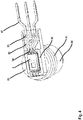
- the bottom 92 has a profiled structure to receive the sensor element 5. It is on the FIG. 4 directed.
- the underside 92 has a border 93, which forms a recess into which the sensor element 5 can be inserted.
- a plurality of rib-shaped and pin-shaped projections 94, 95 are provided, so that conductor tracks 59 of the sensor element 5 are exactly positioned and held in the intended position.
- the underside 92 of the second portion 90 is open to the outside, so that the sensor element 5 can be easily inserted into the recess.
- the housing part 70 is encapsulated together with the sensor element and the shaft element 20. A cover of the sensor element 5 is not necessary.
- the housing 7 of the sensor device 1 on the one hand has a plurality of fastening members 99, of which only one in FIG. 1 is exemplified, via which the housing 7 can be fastened by means of screws or the like to a motor vehicle. Furthermore, the housing 7 has an oval-shaped sleeve 73, which serves for receiving a plug connection. In the sleeve 73, for example, a plug for a printed circuit board can be accommodated, which are connected to the conductor tracks 59 of the sensor element 5. At this sleeve 73, a housing part 70 enclosing section 98 connects. This portion 98 encloses the housing part 70 almost completely except for a region which is covered by the collar 46.
- the first portion 80 of the housing part 70 is enclosed by the housing 7, in particular encapsulated.
- the wall of the first portion 80 of the housing part 70 is pressed against the bearing portions 24, 29 of the shaft member 20.
- the second bearing portion 24 rests directly on the inner side 74 of the housing part 70.
- FIGS. 5 and 6 a second embodiment is shown, which differs essentially by a different design of the inner side 74 of the housing part 70. It is therefore used in the following to the aforementioned reference numerals, as long as they are identical elements.
- the housing part 170 has on the inside 74 of the recess 176 a plurality of segment-shaped contact surfaces 175, 176, with the first and second bearing portion 24, 29 of the shaft member 20 cooperate.
- the inner surface 74 is divided into a plurality of contact surface segments 75, 76 by means of grooves 177, 178.
- the grooves 177, 178 are substantially parallel to the longitudinal axis A of the shaft member or in the vertical direction.
- the grooves extend corresponding to the shape of the blind bore or step-shaped, so that the contact surfaces 176 are also separated from one another here.
- the depth of the grooves 177, 178 may vary depending on the application. They serve as a lubricant reservoir. Furthermore, these grooves can also be used to receive dirt particles or the like. Overall, results in this way, a lower friction during rotation of the shaft member 20 within the housing part 71st
Description
Die Erfindung betrifft einen Sensorvorrichtung zum erfassen einer Rotation gemäß dem Oberbegriff des Hauptanspruchs.The invention relates to a sensor device for detecting a rotation according to the preamble of the main claim.
Aus der
Aus der
Aufgabe der Erfindung ist es daher einen Sensorvorrichtung mit einem einfach herstellbaren Wellenelement aufzuzeigen, das mit geringem Aufwand in ein Gehäuse der Sensorvorrichtung einbaubar ist.The object of the invention is therefore to show a sensor device with a shaft element which can be produced easily, which can be installed with little effort in a housing of the sensor device.
Die Aufgabe wird gelöst mittels einer Sensorvorrichtung der eingangs genannten Art, die durch die kennzeichnenden Merkmale des Anspruchs 1 weitergebildet wird. Weitere vorteilhafte Ausführungsformen sind Gegenstand der Unteransprüche und werden hiermit durch Bezugnahme ausdrücklich zum Gegenstand der Beschreibung gemacht.The object is achieved by means of a sensor device of the type mentioned, which is further developed by the characterizing features of claim 1. Further advantageous embodiments are subject of the dependent claims and are hereby expressly made the subject of the description by reference.
Die Erfindung basiert auf den Grundgedanken mittels des sich zum Wellenende hin verjüngenden Abschnitts eine einfache Herstellbarkeit einer radialen und axialen Lagerung des Wellenelements des Positionsgebers zu erreichen. Die Verjüngung des Lagerabschnitts kann mittels eines sich kontinuierlich verjüngenden oder kegelförmig geformten Abschnitts realisiert werden. Es ist jedoch auch denkbar, die Verjüngung stufenweise zu realisieren. Letztere Variante kann beispielsweise mittels einer Sacklochbohrung realisiert werden. In jedem Fall liegt das Wellenelement so an dem Gehäuseteil im Bereich des Lagerabschnitts an, so dass das Wellenelement zum einen in radialer Richtung als auch in eine axiale Richtung abgestützt wird. Im Falle der stufenweisen Ausgestaltung des Lagerabschnitts ergibt sich mindestens eine quer zur Längsachse der Welle ausgerichtete Kontaktfläche und eine daran anschließende radial um die Längsachse laufende Kontaktfläche zwischen dem Wellenelement und dem Gehäuseteil.The invention is based on the basic idea of achieving a simple producibility of a radial and axial mounting of the shaft element of the position sensor by means of the section tapering towards the shaft end. The taper of the bearing portion can be realized by means of a continuously tapering or conically shaped portion. However, it is also conceivable to realize the taper gradually. The latter variant can be realized for example by means of a blind hole. In any case, the shaft element rests on the housing part in the region of the bearing section, so that the shaft element is supported on the one hand in the radial direction as well as in an axial direction. In the case of the stepwise configuration of the bearing section, there is at least one contact surface oriented transversely to the longitudinal axis of the shaft and an adjoining contact surface between the shaft element and the housing part running radially around the longitudinal axis.
Die Anordnung des sich verjüngenden Abschnitts am zweiten Wellenende, wo auch ein Magnetelement als Signalgeber angeordnet ist, hat den Vorteil, dass dieser lagesensitive Bereich unmittelbar gelagert wird und dadurch positionstreu bleibt. Dadurch kann bereits mit einem Lagerabschnitt eine ausreichende Positionstreue des Wellenelements sichergestellt werden. Durch die sich zum Wellenende verjüngende Form kann das Wellenelement des Weiteren von außen bzw. von oben in das Innere des Gehäuseteils eingeschoben werden, so dass es möglich ist das Wellenelement einstückig mit dem Hebelelement auszubilden und zugleich mit einem Schritt innerhalb des Gehäuseteils zu montieren, wobei weitere Justierungsschritte hiervon nicht berücksichtigt sind. Dieser Aufbau vereinfacht zudem die Trennung der zwei Abschnitte des Gehäuseteils und damit auch die Trennung des Sensorelements vor äußeren Einflüssen, die innerhalb des ersten Abschnitts des Gehäuseteils vorliegen können. Der Begriff Lagerabschnitt wird im Sinne der Erfindung dafür verwendet, um einen Abschnitt oder Bereich zu beschreiben, in der das Wellenelement bzw. Gehäuseteils in erfindungsgemäßer Weise geformt sind, um eine Lagerung des Wellenelements am Gehäuseteil zu erreichen. Daher sind die Lagerabschnitte am Wellenelement und am Gehäuseteil so zueinander ausgerichtet, dass sie miteinander in Kontakt stehen. Durch den unmittelbaren Kontakt zwischen dem Gehäuseteil und dem Wellenelement im Bereich des Lagerabschnitts kommt es zwischen den beiden Teilen bei einer Rotation des Wellenelements zu Reibungen. Diese Reibungen sind jedoch für viele Anwendungsfälle in gewisser Höhe hinnehmbar. Um jedoch zu hohe Reibungen zwischen dem Gehäuseteil und dem Wellenelement zu vermeiden besteht außerhalb des Lagerabschnitts kein Kontakt zwischen den beiden teilen. Es besteht also zwischen dem Wellenelement und dem Gehäuseteil außerhalb des Lagerabschnitts ein Luftspalt. Auf dieser Weise können die Lagerabschnitte auch derart zueinander ausgerichtet werden, um die Reibungshöhe bzw. -intensität durch Herstellungsmaßnahmen oder Konstruktionsmaßnahmen in gewünschter einzustellen.The arrangement of the tapered section on the second shaft end, where a magnetic element is arranged as a signal generator, has the advantage that this position-sensitive area is stored directly and thus remains positionally stable. As a result, sufficient positional fidelity of the shaft element can already be ensured with a bearing section. By tapering to the shaft end shape, the shaft element can be further inserted from the outside or from above into the interior of the housing part, so that it is possible that Form shaft element integrally with the lever element and at the same time to install with a step within the housing part, with further adjustment steps thereof are not taken into account. This structure also simplifies the separation of the two sections of the housing part and thus also the separation of the sensor element from external influences that may be present within the first portion of the housing part. The term bearing portion is used in the context of the invention to describe a portion or region in which the shaft member or housing part are formed in accordance with the invention, in order to achieve a bearing of the shaft member on the housing part. Therefore, the bearing portions on the shaft member and the housing part are aligned with each other so that they are in contact with each other. Due to the direct contact between the housing part and the shaft element in the region of the bearing section, friction occurs between the two parts during a rotation of the shaft element. However, these frictions are acceptable to some extent for many applications. However, to avoid too high friction between the housing part and the shaft member is outside the bearing portion no contact between the two parts. Thus, there is an air gap between the shaft element and the housing part outside the bearing section. In this way, the bearing portions can also be aligned with each other in such a way to adjust the friction level or intensity by manufacturing measures or design measures in the desired.
Das Gehäuseteil ist erfindungsgemäß als ein vom Gehäuse der Sensorvorrichtung separates Teil ausgebildet, das durch Umspritzen mit dem Gehäuse verbunden werden kann bzw. in das Gehäuse integriert werden kann. Alternativ stellt das Gehäuseteil einen Bereich bzw. Abschnitt eines einstückig ausgebildeten Gehäuses dar. Der erste und zweite Abschnitt des Gehäuseteils sind erfindungsgemäß derart voneinander getrennt, so dass ein Durchfluss von Feuchtigkeit durch Wasser, Öl oder vergleichbaren Medien von einem zum anderen Abschnitt nicht möglich ist, bspw. um das Sensorelement davor zu schützen. Die erfindungsgemäße Sensorvorrichtung wird dadurch in vorteilhafter Weise weitergebildet, dass der erste Lagerabschnitt stufenweise verjüngend geformt ist. Die stufenweise Ausführung des Lagerabschnitts hat den Vorteil der leichten Herstellbarkeit. Ferner hat diese Ausführungsform den Vorteil, dass der Bereich zum zweiten Wellenende hin mittels der Kontaktflächen zwischen dem Wellenelement und dem Gehäuseteil abgedichtet werden kann. Der Bereich zwischen dem Magnetelement und dem Gehäuse kann auf diese Weise wirksam gegen Schmutz und Feuchtigkeit geschützt werden, die möglicherweise die Wirkung des Sensorelements beeinträchtigen könnten. Ferner ermöglicht die stufenweise Ausführung des Lagerabschnitts den axialen Abstand zwischen dem Magnetelement und dem Sensorelement möglichst genau einzustellen.According to the invention, the housing part is designed as a separate part from the housing of the sensor device, which part can be connected to the housing by encapsulation or can be integrated into the housing. Alternatively, the housing part constitutes an area or section of an integrally formed housing. The first and second section of the housing Housing part according to the invention are so separated from each other, so that a flow of moisture through water, oil or similar media from one to the other section is not possible, for example. To protect the sensor element from it. The sensor device according to the invention is characterized in an advantageous manner that the first bearing portion is formed stepwise tapered. The stepwise execution of the bearing section has the advantage of easy manufacturability. Furthermore, this embodiment has the advantage that the area towards the second shaft end can be sealed off by means of the contact surfaces between the shaft element and the housing part. The area between the magnetic element and the housing can be effectively protected in this way against dirt and moisture, which could possibly affect the effect of the sensor element. Furthermore, the stepwise design of the bearing portion allows the axial distance between the magnetic element and the sensor element set as accurately as possible.
Die erfindungsgemäße Sensorvorrichtung wird dadurch in vorteilhafter Weise weitergebildet, dass der erste Lagerabschnitt jeweils eine im Wesentlichen horizontal und eine im Wesentlichen vertikal verlaufende Kontaktfläche aufweist, die unmittelbar aneinander angrenzen. Mittels der im Wesentlichen orthogonal zueinander ausgerichteten Kontaktflächen ist die Lagerung des Wellenelements besonders einfach erreichbar.The sensor device according to the invention is characterized in an advantageous manner that the first bearing portion each having a substantially horizontal and a substantially vertically extending contact surface, which adjoin one another directly. By means of the substantially orthogonal aligned contact surfaces, the storage of the shaft member is particularly easy to reach.
Die erfindungsgemäße Sensorvorrichtung wird dadurch in vorteilhafter Weise weitergebildet, dass das Gehäuseteil und das Wellenelement im Bereich des ersten Lagerabschnitts passgenau hergestellt ist. Durch die Passgenauigkeit werden eine hohe Positionstreue und eine gute Abdichtung des Bereiches des zweiten Wellenendes erreicht.The sensor device according to the invention is further developed in an advantageous manner, that the housing part and the shaft member is made in the area of the first bearing portion accurately. Due to the accuracy of fit, a high positional fidelity and a good seal of the area of the second shaft end are achieved.
Die erfindungsgemäße Sensorvorrichtung wird dadurch in vorteilhafter Weise weitergebildet, dass die Position der horizontalen Kontaktflächen passgenau gefertigt ist. Auf diese Weise kann der axiale Abstand zwischen dem Magnetelement und dem Sensorelement besonders genau eingestellt werden. Passgenau soll in diesem Zusammenhang daher bedeuten, dass der Toleranzbereich zu Herstellung oder Bearbeitung des betroffenen Bereichs bzw. Abschnitts zu anderen Bereichen signifikant kleiner ist, um eine höhere Genauigkeit der Maße und relativen Position zu erreichen.The sensor device according to the invention is characterized in an advantageous manner that the position of the horizontal contact surfaces is made precisely. In this way, the axial distance between the magnetic element and the sensor element can be set particularly accurately. In this context, it should therefore be perfectly accurate that the tolerance range for producing or processing the affected area or section to other areas is significantly smaller in order to achieve greater accuracy of the dimensions and relative position.
Die erfindungsgemäße Sensorvorrichtung wird dadurch in vorteilhafter Weise weitergebildet, dass das zweite Wellenende nicht in Berührung mit dem Gehäuseteil steht. Zwar erhöht sich dadurch der Abstand zwischen dem Magnetelement und dem Sensorelement. Durch einen geringen Luftabstand zwischen dem Gehäuseteil und dem zweiten Wellenende wird jedoch die Reibung bei Rotation des Wellenelements vermieden, was insgesamt eine flüssigere Rotation des Wellenelements ermöglicht.The sensor device according to the invention is characterized in an advantageous manner that the second shaft end is not in contact with the housing part. Although this increases the distance between the magnetic element and the sensor element. However, by a small clearance between the housing part and the second shaft end, the friction is avoided during rotation of the shaft member, which allows a total of a more fluid rotation of the shaft member.
Die erfindungsgemäße Sensorvorrichtung wird dadurch in vorteilhafter Weise weitergebildet, dass das Gehäuseteil und das Wellenelement zwischen dem ersten Wellende und dem ersten Lagerabschnitt jeweils einen zweiten Lagerabschnitt zur radialen Lagerung des Wellenelements aufweist. Das Wellenelement wird gemäß dieser Ausführungsform lediglich durch die beiden Lagerabschnitte gelagert und steht auch nur im Bereich der Lagerabschnitte mit dem Gehäuseteil im Kontakt. Durch die weitere radiale Lagerung am zweiten Lagerabschnitt wird ein Kippen des Wellenelements um die Längsachse wirksam verhindert. Auf diese Weise ist es möglich das Wellenelement besonders positionstreu relativ zum Gehäuseteil und somit auch zum Sensorelement zu halten. Das Wellenelement und das Gehäuseteil sind vorteilhafterweise im Bereich des zweiten Lagerabschnitts passgenau zueinander ausgearbeitet. Weitere radiale Lagerungsabschnitte sind zwar auch denkbar, jedoch bietet die Kombination aus den ersten und zweiten Lagerungsabschnitten die ideale Lösung zur kostengünstigen und sicheren Lagerung des Wellenelements.The sensor device according to the invention is characterized in an advantageous manner that the housing part and the shaft member between the first shaft end and the first bearing portion each having a second bearing portion for the radial mounting of the shaft member. According to this embodiment, the shaft element is supported only by the two bearing sections and is also in contact with the housing part only in the region of the bearing sections. The further radial bearing on the second bearing portion effectively prevents the shaft element from tilting about the longitudinal axis. In this way, it is possible to keep the shaft element in a particularly positionally stable manner relative to the housing part and thus also to the sensor element. The shaft element and the housing part are advantageously designed to fit each other in the area of the second bearing section. Other radial bearing sections Although conceivable, but the combination of the first and second storage sections provides the ideal solution for cost-effective and safe storage of the shaft element.
Die erfindungsgemäße Sensorvorrichtung wird dadurch in vorteilhafter Weise weitergebildet, dass das Wellenelement im zweiten Lagerabschnitt ein Vorsprung mit einer im Wesentlichen parallel zur Längsachse des Wellenelements verlaufenden Kontaktfläche zum Gehäuseteil ausgebildet ist. Auf diese Weise ist die Lagerung am zweiten Lagerabschnitt besonders einfach realisierbar.The sensor device according to the invention is further developed in an advantageous manner, that the shaft element in the second bearing portion is a projection formed with a substantially parallel to the longitudinal axis of the shaft member extending contact surface to the housing part. In this way, the storage on the second storage section is particularly easy to implement.
Die erfindungsgemäße Sensorvorrichtung wird dadurch in vorteilhafter Weise weitergebildet, dass die Oberfläche des Gehäuseteils oder Wellenelements zumindest im Bereich eines Lagerabschnitts ein Gleitmittel aufweist. Auf diese Weise kann die Reibung zwischen dem Wellenelement und dem Gehäuseteil wirksam verringert werden. Beispielsweise könnte die Kontaktfläche am Wellenelement oder am Gehäuseteil mit einer auf die Oberfläche aufgebrachten Schmierschicht, z. B. PTFE, ausgestattet sein. Es ist jedoch auch denkbar das Wellenelement oder das Gehäuseteil selbst zumindest im Bereich eines Lagerabschnitts mittels eines möglichst reibungsarmen Materials auszubilden.The sensor device according to the invention is characterized in an advantageous manner that the surface of the housing part or shaft member has a lubricant at least in the region of a bearing portion. In this way, the friction between the shaft member and the housing part can be effectively reduced. For example, the contact surface on the shaft element or on the housing part with a surface applied to the lubricating layer, for. As PTFE, be equipped. However, it is also conceivable to form the shaft element or the housing part itself at least in the region of a bearing section by means of a material with as little friction as possible.
Die erfindungsgemäße Sensorvorrichtung wird dadurch in vorteilhafter Weise weitergebildet, dass das Gehäuseteil im Bereich mindestens eines Lagerabschnitts segmentförmig ausgebildete Kontaktflächen aufweist, wobei die Kontaktflächen mittels Nuten oder Ausnehmungen voneinander getrennt sind. Durch die segmentartigen bzw. segmentförmig ausgebildeten Kontaktflächen wird die Lagerung des Wellenelements am Gehäuseteil weiterhin sichergestellt. Mittels der Freiräume zwischen den Kontaktflächen verringert sich insgesamt die Größe der Gesamtkontaktfläche, so dass die Reibung zwischen dem Wellenelement und dem Gehäuseteil verringert wird. Des Weiteren haben die Freiräume bzw. Nuten den Vorteil, dass Schmutzpartikel oder dergleichen sich nicht im Bereich der Kontaktflächen ablagern, sondern durch Rotation des Wellenelements in die Nuten befördert werden. Die zwischen den Kontaktflächen angeordneten Nutten können auch als Speicher für Schmiermittel verwendet werden.The sensor device according to the invention is further developed in an advantageous manner that the housing part has in the region of at least one bearing portion segmentally shaped contact surfaces, wherein the contact surfaces are separated by grooves or recesses. Due to the segment-like or segment-shaped contact surfaces, the bearing of the shaft member is further ensured on the housing part. Overall, the size of the total contact surface is reduced by means of the free spaces between the contact surfaces. so that the friction between the shaft member and the housing part is reduced. Furthermore, the free spaces or grooves have the advantage that dirt particles or the like do not deposit in the area of the contact surfaces, but are conveyed into the grooves by rotation of the shaft element. The hookers disposed between the contact surfaces may also be used as reservoirs for lubricants.
Die erfindungsgemäße Sensorvorrichtung wird dadurch in vorteilhafter Weise weitergebildet, dass die Nuten oder Ausnehmungen zum Aufnehmen eines Schmiermittels vorgesehen sind. Die Lagerabschnitte werden vor Montage des Wellenelements in das Gehäuseteil mit einem Schmiermittel versehen. Durch die Nuten kann eine größere Menge von Schmiermittel in die Lageabschnitte eingebracht werden.The sensor device according to the invention is characterized in an advantageous manner that the grooves or recesses are provided for receiving a lubricant. The bearing sections are provided with a lubricant before mounting the shaft member in the housing part. Through the grooves, a larger amount of lubricant can be introduced into the bearing sections.
Die erfindungsgemäße Sensorvorrichtung wird dadurch in vorteilhafter Weise weitergebildet, dass die Passung im Bereich des Lagerabschnitts derart gestaltet ist, den Bereich des zweiten Wellenendes abzudichten.The sensor device according to the invention is further developed in an advantageous manner, that the fit in the region of the bearing portion is designed to seal the region of the second shaft end.
Die erfindungsgemäße Sensorvorrichtung wird dadurch in vorteilhafter Weise weitergebildet, dass das Sensorelement einen Chip aufweist, wobei das Gehäuseteil im ersten Abschnitt eine Ausnehmung zum Aufnehmen des Chips oder eines elektronischen Bauteils zum Erfassen des Magnetfeldes des Magnetlements aufweist, wobei die Position der Ausnehmung präzise zur Position des Wellenelements ausgerichtet ist. Auf diese Weise wird sichergestellt, dass auch das Sensorelement über die gesamte Lebensdauer der Sensorvorrichtung die relative Position zum Magnetelement beibehält.The sensor device according to the invention is characterized in an advantageous manner that the sensor element comprises a chip, wherein the housing part in the first portion has a recess for receiving the chip or an electronic component for detecting the magnetic field of the Magnetlements, wherein the position of the recess precisely to the position of the Shaft element is aligned. In this way, it is ensured that the sensor element also maintains the relative position to the magnetic element over the entire service life of the sensor device.
Die erfindungsgemäße Sensorvorrichtung wird dadurch in vorteilhafter Weise weitergebildet, dass der Positionsgeber ein Hebelelement aufweist, das am ersten Wellenende angeordnet ist und mit dem Wellenelement einstückig ausgebildet ist, wobei im Bereich zwischen dem Wellenelement und dem Hebelelement eine Ausnehmung ausgebildet ist, worüber der Positionsgeber in das Gehäuseteil einrastbar ist. Auf diese Weise kann der Positionsgeber besonders aufwandsarm montiert werden. Das Einrasten des Positionsgebers am Gehäuseteil im Verbindungsbereich zwischen dem Hebelelement und dem Wellenelement hat des Weiteren den Vorteil, dass das Eindringen von Schmutz und Feuchtigkeit in das Gehäuseteil teilweise verhindert werden kann. Je nach Anwendungsfall kann dieser Bereich auch mit einer zusätzlichen Dichtung versehen werden.The sensor device according to the invention is characterized in an advantageous manner that the position sensor a Lever element which is arranged on the first shaft end and is integrally formed with the shaft member, wherein in the region between the shaft member and the lever element, a recess is formed, about which the position sensor can be latched into the housing part. In this way, the position sensor can be mounted particularly low effort. The engagement of the position sensor on the housing part in the connecting region between the lever element and the shaft element further has the advantage that the penetration of dirt and moisture into the housing part can be partially prevented. Depending on the application, this area can also be provided with an additional seal.
Die Erfindung umfasst ferner den Aspekt die erfindungsgemäße Sensorvorrichtung als Höhenstandsensor zu verwenden. Die vorgenannten Ausführungsformen sind insbesondere für den Einsatz in einem Höhenstandsensor besonders gut geeignet, da hier die Rotationsgeschwindigkeiten und Rotationshübe relativ gering sind und somit eine Kontaktlagerung zwischen dem Wellenelement und dem Gehäuseteil auch über eine längere Lebensdauer haltbar sind.The invention further includes the aspect of using the sensor device according to the invention as a height sensor. The aforementioned embodiments are particularly well suited for use in a level sensor, since the rotational speeds and rotational strokes are relatively low and thus a contact bearing between the shaft member and the housing part over a longer service life are preserved.
Die Erfindung wird nachfolgend anhand von Figuren und eines Ausführungsbeispiels näher beschrieben. Es zeigen:
-
Figur 1 eine perspektivische Teilschnittansicht eines ersten Ausführungsbeispiels der erfindungsgemäßen Sensorvorrichtung, -
Figur 2 -
Figur 3Figur 2 -
Figur 4 eine perspektivische Ansicht auf die Unterseite des Gehäuseteils mit einem Sensorelement, -
Figur 5 -
Figur 6 eine Querschnittansicht des Gehäuseteils ausFigur 5 .
-
FIG. 1 2 shows a perspective partial sectional view of a first exemplary embodiment of the sensor device according to the invention, -
FIG. 2 a perspective partial sectional view of parts of the sensor device, -
FIG. 3 a sectional view of a portion of the inFIG. 2 parts shown, -
FIG. 4 a perspective view of the underside of the housing part with a sensor element, -
FIG. 5 a partial perspective sectional view of the housing part of the second embodiment, and -
FIG. 6 a cross-sectional view of the housing partFIG. 5 ,
Der Übersichtshalber wurden in einigen Figuren einige Bezugszeichen ausgelassen. Diese fehlenden Bezugszeichen sind aus den anderen Figuren ergänzend hinzuzudenken. Die Beschreibung ist daher auch auf die teilweise ohne Bezugszeichen versehenen Elemente ebenso anwendbar.For the sake of clarity, some reference numbers have been omitted in some figures. These missing reference numerals are to be considered complementary from the other figures. The description is therefore also applicable to the partially provided with no reference numerals elements as well.
Hierzu ist die Sensorvorrichtung 1 mit einer Höhenverstellungsvorrichtung des Kraftfahrzeugs verbunden, bspw. einem Federbein. Wenn die Höhe der Fahrzeugs-Karosserie verstellt wird, kann die Höhe der Verstellung mittels der Sensorvorrichtung 1 ermittelt werden. Bei diesem Anwendungsfall ist die Sensorvorrichtung Schmutz und Wasser ausgesetzt, da es im Bereich der Räder angeordnet ist. Daher ist es notwendig die funktionswesentlichen Teile der Sensorvorrichtung 1 vor den äußeren Einflüssen zu schützen. Dies betrifft insbesondere die Elektronik. Insbesondere im Hinblick auf die Langlebigkeit ist es wesentlich, dass das Innere der Sensorvorrichtung 1 im wesentlichen Trocken bleibt.For this purpose, the sensor device 1 is connected to a height adjustment device of the motor vehicle, for example a shock absorber. If the height of the vehicle body is adjusted, the height of the adjustment by means of the sensor device 1 can be determined. In this application, the sensor device is exposed to dirt and water, as it is located in the area of the wheels. Therefore, it is necessary to protect the functionally essential parts of the sensor device 1 from external influences. This concerns in particular the electronics. In particular, with regard to the longevity, it is essential that the interior of the sensor device 1 remains substantially dry.
Der Positionsgeber 2 weist ein Wellenelement 20 mit einem ersten und zweiten Wellende 21, 22 auf. Der Positionsgeber 2 weist ferner ein Hebelelement 40 auf, das am ersten Wellenende 21 angeordnet ist. Das Wellenelement 20 und das Hebelelement 40 sind einstückig ausgebildet. Das Hebelelement 40 und das Wellenelement 20 sind vorzugsweise als ein Spritzgussteil gefertigt. An dem freien Ende weist das Hebelelement 40 eine Bohrung 41 (s.
Das Hebelelement 40 ist flachstabartig ausgebildet. Die oberen und unteren Seiten 43, 44 des Wellenelements 40 sind im Wesentlichen ebenförmig ausgebildet. Die in den
Das Wellenelement 20 ist senkrecht zum Hebelelement 40 ausgerichtet. Es erstreckt sich von der Unterseite 44 des Hebelelements weg, wobei der Übergang von der inneren Lippe 46b zum Wellenelement 20 fließend ist. Bei einer nicht einstückigen Ausführung des Wellenelements 20 und des Hebelelements 40 könnte die Verbindung zwischen den beiden Elementen mittels einer Steckverbindung oder dergleichen realisiert werden. Das Wellenelement 20 ist zylinderförmig bzw. leicht kegelförmig ausgebildet und weist eine sich leicht zum Wellenende 22 hin verjüngende Form auf. Der Radius des Wellenelements 20 ist derart gewählt, so dass kein Kontakt zwischen dem Wellenelement 20 und der Innenseite 74 des Gehäuseteils 70 entsteht. Stattdessen weist das Wellenelement 20 zwei Lagerabschnitte 24, 29 auf, über die das Wellenelement 20 an der Innenseite 74 des Gehäuseteils 70 anliegt und somit das Wellenelement 20, aber auch das Hebelelement 40 indirekt in radialer axialer Richtung am Gehäuseteil 70 bzw. Gehäuse 7 lagert.The
Der erste Lagerabschnitt 24 ist in etwa der Mitte zwischen dem zweiten Wellenende 22 und dem Vorsprung 47 an der inneren Lippe 46b angeordnet. Der erste Lagerabschnitt 24 lagert das Wellenelement 20 in radialer Richtung, was in
Der zweite Lagerabschnitt 29 ist in axialer Richtung vom ersten Lagerabschnitt 24 beabstandet angeordnet und befindet sich im Bereich des zweiten Wellenendes 22 des Wellenelements 20. Der zweite Lagerabschnitt 29 weist einen sich zum Wellenende hin verjüngend geformten Abschnitt auf. Hier liegt das Wellenelement 20 am Gehäuseteil an. Im Ausführungsbeispiel ist der zweite Lagerabschnitt als ein Wellenabsatz ausgebildet, der mit einer dazu korrespondierenden Sacklochbohrung am Gehäuseteil 71 zusammenwirkt, um das Wellenelement 20 sowohl in radialer als auch in eine axialer Richtung zu lagern, wie in
Das zweite Wellenende 22 wiederum ist so ausgebildet, dass es nicht mit dem Gehäuseteil 71 in Kontakt steht. Wie in
Vorteilhafterweise ist das Wellenelement 20 im Bereich der der Lagerabschnitte 24, 29 passgenau hergestellt. Dies betrifft zum einen die Toleranz bzgl. der Position relativ zur Längsachse A des Wellenelements. Insbesondere ist es vorteilhaft die horizontale Kontaktfläche 29a in Bezug auf den Abstand zur Stirnfläche des zweiten Wellenendes 22 hin passgenau bzw. mit einer geringen Toleranz zu fertigen. Des Weiteren betrifft die Passgenauigkeit auch die radialen Abmessungen der Kontaktflächen 29b und 26 der ersten und zweiten Lagerabschnitte 24, 29, um eine feste Lagerung bei gleichzeitig geringer Reibung zu erreichen. Die Reibung kann beispielsweise auch mittels Schmiermittel, eines geeigneten Materials bzw. Materialpaares des Gehäuseteils 70 und Wellenelements 20 verringert werden. Eine hohe Passgenauigkeit hat aber darüber hinaus auch den Vorteil, dass der Bereich des zweiten Wellenendes ohne zusätzliche Dichtmittel abdichtbar ist.Advantageously, the
Das Gehäuseteil 70 ist, wie in
Der erste Abschnitt 80 des Gehäuseteils 70 weist eine zylinderförmige Grundform auf (s.
Der zweite Abschnitt 90 des Gehäuseteils 70 ist im Wesentlichen plattenförmig ausgebildet und an der Stirnseite des ersten Abschnitts bzw. an der Wand 85 angeordnet, die der Öffnung gegenüberliegt. Wie in den
Das Gehäuse 7 der Sensorvorrichtung 1 weist zum einen mehrere Befestigungsglieder 99 auf, wovon nur eines in
In den
Das Gehäuseteil 170 gemäß dem zweiten Ausführungsbeispiel weist an der Innenseite 74 der Ausnehmung 176 mehrere segmentförmig ausgebildete Kontaktflächen 175, 176 auf, die mit dem ersten und zweiten Lagerabschnitt 24, 29 des Wellenelements 20 zusammenwirken. Im Bereich der Lagerabschnitte 24, 29 ist die Innenfläche 74 mittels Nuten 177, 178 in mehrere Kontaktflächensegmente 75, 76 unterteilt. Die Nuten 177, 178 verlaufen im wesentlichen parallel zu der Längsachse A des Wellenelements bzw. in vertikaler Richtung. Im Bereich des ersten Lagerabschnitts 24 ergeben sich dadurch entlang der Umfangsfläche umlaufend mehrere rechteckförmig ausgebildete Kontaktflächen 175, die die mittels der Nuten 177 unterbrochen werden. Im Bereich des zweiten Lagerabschnitts 29 verlaufen die Nuten korrespondierend zur Form der Sacklochbohrung bzw. stufenförmig, so dass die Kontaktflächen 176 auch hier voneinander getrennt sind. Die Tiefe der Nuten 177, 178 kann je nach Anwendungsfall variieren. Sie dienen zum einen als Schmiermittelreservoir. Des weiteren können diese Nuten auch dazu genutzt werden, um Schmutzpartikel oder dergleichen aufzunehmen. Insgesamt ergibt sich auf diese Weise eine geringere Reibung bei Rotation des Wellenelements 20 innerhalb des Gehäuseteils 71.The
Claims (15)
- Sensor device (1) for sensing a rotation, having- a position encoder (2) having a shaft element (20) which has a first and a second shaft end (22), wherein the rotation to be sensed is introduced via the first shaft end, and wherein the shaft element contains a magnet element (51) at the second shaft end (22),- a sensor element (5) for sensing the rotation of the magnet element, and- a housing part (70), integrated into a housing (7), having at least two portions (80, 90) that are separated from one another, said housing part being configured to receive the shaft element (20) and the sensor element (5), wherein the shaft element (20) of the position encoder (2) is mounted on the first portion (80) and the sensor element (5) is arranged in the second portion (90),characterized in that the housing part (70) and the shaft element (20) each have, in the region of the second shaft end (22), a first bearing portion (29) which is shaped in a manner narrowing toward the shaft end and at which the shaft element (20) bears on the housing part (70) in order to mount the position encoder on the housing part (70), wherein the housing part (70) is configured as a part that is separate from the housing (7) and can be connected to the housing by overmoulding.
- Sensor device (1) according to Claim 1, characterized in that the first bearing portion (29) is shaped in a manner narrowing in a stepped manner.
- Sensor device (1) according to Claim 1 or 2, characterized in that the first bearing portion (29) has a substantially horizontally extending contact face (29a) and a substantially vertically extending contact face (29b), which immediately adjoin one another.
- Sensor device (1) according to one of the preceding claims, characterized in that the housing part (70) and the shaft element (20) are produced with a precise fit in the region of the first bearing portion.
- Sensor device (1) according to one of the preceding claims, characterized in that the position of the horizontal contact faces (29a) is produced with a precise fit.
- Sensor device (1) according to one of the preceding claims, characterized in that the second shaft end (22) is not in contact with the housing part (70).
- Sensor device (1) according to one of the preceding claims, characterized in that the housing part (20) and the shaft element each have, between the first shaft end and the first bearing portion (29), a second bearing portion (24) for radially mounting the shaft element (20) .
- Sensor device (1) according to the preceding claim, characterized in that the shaft element (20) is formed, in the second bearing portion (24), with a protrusion having a contact face (26), extending substantially parallel to the longitudinal axis of the shaft element, with respect to the housing part (70).
- Sensor device (1) according to one of the preceding claims, characterized in that the surface of the housing part or shaft element (20) has a lubricant at least in the region of one bearing portion (24, 29).
- Sensor device (1) according to one of the preceding claims, characterized in that the housing part (70) has contact faces (176) formed in a segmented manner in the region of at least one bearing portion (24, 29), wherein the contact faces (176) are separated from one another by means of grooves (178).
- Sensor device (1) according to the preceding claim, characterized in that the grooves (178) are provided to receive a lubricant.
- Sensor device (1) according to one of Claims 1-9, characterized in that the fit in the region of the first or second bearing portion (24, 29) is designed so as to seal off the region of the second shaft end (22).
- Sensor device (1) according to one of the preceding claims, characterized in that the sensor element (5) has a chip, wherein the housing part (70) has, in the second portion (90), a recess for receiving the chip, wherein the position of the recess is aligned precisely with the position of the shaft element.
- Sensor device (1) according to one of the preceding claims, characterized in that the position encoder (2) has a lever element (40) which is arranged at the first shaft end and is formed integrally with the shaft element (20), wherein, in the region between the shaft element and the lever element, a recess (46) is formed, via which the position encoder is able to be latched in place in the housing part (70).
- Use of the sensor device (1) according to one of the preceding claims as a ride-height sensor.
Applications Claiming Priority (2)
| Application Number | Priority Date | Filing Date | Title |
|---|---|---|---|
| DE102014219390 | 2014-09-25 | ||
| PCT/EP2015/072035 WO2016046341A1 (en) | 2014-09-25 | 2015-09-24 | Integrated shaft bearing for a sensor |
Publications (2)
| Publication Number | Publication Date |
|---|---|
| EP3198232A1 EP3198232A1 (en) | 2017-08-02 |
| EP3198232B1 true EP3198232B1 (en) | 2019-01-09 |
Family
ID=54199217
Family Applications (1)
| Application Number | Title | Priority Date | Filing Date |
|---|---|---|---|
| EP15770867.8A Active EP3198232B1 (en) | 2014-09-25 | 2015-09-24 | Integrated shaft bearing for a sensor |
Country Status (6)
| Country | Link |
|---|---|
| US (1) | US10295370B2 (en) |
| EP (1) | EP3198232B1 (en) |
| KR (1) | KR101901078B1 (en) |
| CN (1) | CN107076573A (en) |
| DE (1) | DE102015218425A1 (en) |
| WO (1) | WO2016046341A1 (en) |
Families Citing this family (11)
| Publication number | Priority date | Publication date | Assignee | Title |
|---|---|---|---|---|
| DE102015212633A1 (en) * | 2015-07-07 | 2017-01-12 | Continental Teves Ag & Co. Ohg | Sensor arrangement with modular construction |
| DE102016213775A1 (en) * | 2016-07-27 | 2018-02-01 | Continental Teves Ag & Co. Ohg | Angle sensor for detecting a rotation angle |
| DE102016217814B4 (en) | 2016-09-16 | 2018-07-26 | Continental Teves Ag & Co. Ohg | angle sensor |
| DE102017107430A1 (en) * | 2017-04-06 | 2018-10-11 | Schwing Gmbh | Rotation angle sensor holding system |
| DE102017222999B4 (en) | 2017-12-18 | 2021-10-21 | Robert Bosch Gmbh | Sensor device for a steering system of a vehicle |
| DE102018217281A1 (en) | 2018-10-10 | 2020-04-16 | Continental Teves Ag & Co. Ohg | Angle sensor for detecting an angle of rotation |
| DE102019210067A1 (en) * | 2019-07-09 | 2021-01-14 | Robert Bosch Gmbh | Measuring device for a sensor arrangement for contactless detection of a movement of a body |
| DE102020201134A1 (en) * | 2020-01-30 | 2021-08-05 | Robert Bosch Gesellschaft mit beschränkter Haftung | Sensor arrangement, actuating device for a brake system |
| DE102020216344B4 (en) | 2020-12-18 | 2022-09-08 | Continental Teves Ag & Co. Ohg | Ride level sensor made from two one-piece units |
| DE102020216342B4 (en) | 2020-12-18 | 2022-11-10 | Continental Automotive Technologies GmbH | Ride level sensor with a bearing having latching means |
| WO2023004384A1 (en) * | 2021-07-21 | 2023-01-26 | Cts Corporation | Motor vehicle chassis sensor with overmolded and encapsulated magnet |
Family Cites Families (13)
| Publication number | Priority date | Publication date | Assignee | Title |
|---|---|---|---|---|
| DE19733719C1 (en) | 1997-08-04 | 1999-04-15 | Hella Kg Hueck & Co | Motor vehicle lever sensor |
| EP1520346B1 (en) | 2001-02-24 | 2008-01-23 | Marquardt GmbH | Device for adjustment of rotation angles |
| JP2004191163A (en) * | 2002-12-11 | 2004-07-08 | Matsushita Electric Ind Co Ltd | Rotation angle detector |
| US20040174159A1 (en) * | 2003-03-05 | 2004-09-09 | Claudia Ramirez | Securement feature for rotary position sensor |
| US7230419B2 (en) | 2005-06-03 | 2007-06-12 | Delphi Technologies, Inc. | Rotary position sensor |
| US7208943B2 (en) * | 2005-06-03 | 2007-04-24 | Delphi Technologies, Inc. | Electrical device enclosure |
| DE102007032139A1 (en) * | 2007-06-30 | 2009-01-02 | Robert Bosch Gmbh | Control device with position sensor |
| DE102007034099B4 (en) | 2007-07-21 | 2020-10-15 | Hartmann-Exact Gmbh | Device for the contactless detection of the relative positions of two parts that can be moved to one another |
| DE102011079446A1 (en) | 2011-07-20 | 2013-02-07 | Robert Bosch Gmbh | Sensor device, in particular for use in a motor vehicle |
| DE102011118775B3 (en) | 2011-11-17 | 2013-04-04 | Hartmann-Exact Gmbh | Device for performing contactless acquisition of relative position of two chassis sensors of motor car, has receiving chamber and pivot shaft whose outer surfaces are configured such that shaft is latched with insert |
| DE102012106021A1 (en) | 2012-07-05 | 2014-05-08 | Hella Kgaa Hueck & Co. | level sensor |
| US9134200B2 (en) * | 2012-08-17 | 2015-09-15 | Cts Corporation | Motor vehicle chassis sensor |
| DE102014218684B4 (en) | 2014-09-17 | 2024-03-21 | Continental Automotive Technologies GmbH | Device with a hollow shaft and a holder and method for producing such a device |
-
2015
- 2015-09-24 KR KR1020177006730A patent/KR101901078B1/en active IP Right Grant
- 2015-09-24 DE DE102015218425.0A patent/DE102015218425A1/en not_active Withdrawn
- 2015-09-24 CN CN201580048615.4A patent/CN107076573A/en active Pending
- 2015-09-24 EP EP15770867.8A patent/EP3198232B1/en active Active
- 2015-09-24 US US15/504,185 patent/US10295370B2/en active Active
- 2015-09-24 WO PCT/EP2015/072035 patent/WO2016046341A1/en active Application Filing
Non-Patent Citations (1)
| Title |
|---|
| None * |
Also Published As
| Publication number | Publication date |
|---|---|
| WO2016046341A1 (en) | 2016-03-31 |
| KR101901078B1 (en) | 2018-09-20 |
| CN107076573A (en) | 2017-08-18 |
| DE102015218425A1 (en) | 2016-03-31 |
| US10295370B2 (en) | 2019-05-21 |
| KR20170044133A (en) | 2017-04-24 |
| EP3198232A1 (en) | 2017-08-02 |
| US20170276511A1 (en) | 2017-09-28 |
Similar Documents
| Publication | Publication Date | Title |
|---|---|---|
| EP3198232B1 (en) | Integrated shaft bearing for a sensor | |
| DE4242154C2 (en) | Sealing cover | |
| DE2943747C2 (en) | ||
| EP2473767B1 (en) | Water drain valve comprising a shielding diaphragm | |
| DE102007023070B4 (en) | Expansion tank for a hydraulic motor vehicle brake system | |
| WO2000050794A1 (en) | Solenoid valve | |
| DE102007032673A1 (en) | Fluid dynamic bearing system and spindle motor with such a storage system | |
| DE102007037225A1 (en) | Expansion tank for a hydraulic motor vehicle brake system | |
| DE102016003269A1 (en) | Fluid dynamic storage system | |
| DE102016202532A1 (en) | ball joint | |
| DE602005000602T2 (en) | Weatherproof spindle with low friction | |
| WO2002076802A1 (en) | Brake servo comprising a connecting element with a defined angular position | |
| DE102005032631B4 (en) | Fluid dynamic storage system | |
| DE3016231C2 (en) | Sealing arrangement | |
| DE102010029796B4 (en) | Water drain valve for electronics housing and electronics housing with such a water drain valve | |
| DE19648319B4 (en) | Radial piston pump | |
| DE102011118773B4 (en) | Device for non-contact detection of the relative position of two parts that can be moved relative to one another | |
| DE102012019642B3 (en) | Oil sediment bowl closure has translucent element with average diameter that is projected inwards along mounting direction of inner side with respect to direction transverse to direction of outer lateral surface of mounting structure | |
| DE102007025826A1 (en) | Expansion tank for a hydraulic motor vehicle brake system | |
| DE102015200187A1 (en) | Valve device in a motor vehicle and method of manufacture | |
| DE2702394C2 (en) | Contact insert for liquid containers | |
| DE4142727B4 (en) | Speed sensor | |
| DE102004054663B4 (en) | Fluid dynamic bearing arrangement | |
| DE102014007155A1 (en) | Fluid dynamic bearing system for a spindle motor | |
| EP3755909B1 (en) | Ball joint, in particular for a suspension of a vehicle |
Legal Events
| Date | Code | Title | Description |
|---|---|---|---|
| STAA | Information on the status of an ep patent application or granted ep patent |
Free format text: STATUS: THE INTERNATIONAL PUBLICATION HAS BEEN MADE |
|
| PUAI | Public reference made under article 153(3) epc to a published international application that has entered the european phase |
Free format text: ORIGINAL CODE: 0009012 |
|
| STAA | Information on the status of an ep patent application or granted ep patent |
Free format text: STATUS: REQUEST FOR EXAMINATION WAS MADE |
|
| 17P | Request for examination filed |
Effective date: 20170425 |
|
| AK | Designated contracting states |
Kind code of ref document: A1 Designated state(s): AL AT BE BG CH CY CZ DE DK EE ES FI FR GB GR HR HU IE IS IT LI LT LU LV MC MK MT NL NO PL PT RO RS SE SI SK SM TR |
|
| AX | Request for extension of the european patent |
Extension state: BA ME |
|
| DAV | Request for validation of the european patent (deleted) | ||
| DAX | Request for extension of the european patent (deleted) | ||
| STAA | Information on the status of an ep patent application or granted ep patent |
Free format text: STATUS: EXAMINATION IS IN PROGRESS |
|
| 17Q | First examination report despatched |
Effective date: 20180308 |
|
| RAP1 | Party data changed (applicant data changed or rights of an application transferred) |
Owner name: CONTINENTAL TEVES AG & CO. OHG |
|
| GRAP | Despatch of communication of intention to grant a patent |
Free format text: ORIGINAL CODE: EPIDOSNIGR1 |
|
| STAA | Information on the status of an ep patent application or granted ep patent |
Free format text: STATUS: GRANT OF PATENT IS INTENDED |
|
| INTG | Intention to grant announced |
Effective date: 20181016 |
|
| GRAS | Grant fee paid |
Free format text: ORIGINAL CODE: EPIDOSNIGR3 |
|
| GRAA | (expected) grant |
Free format text: ORIGINAL CODE: 0009210 |
|
| STAA | Information on the status of an ep patent application or granted ep patent |
Free format text: STATUS: THE PATENT HAS BEEN GRANTED |
|
| AK | Designated contracting states |
Kind code of ref document: B1 Designated state(s): AL AT BE BG CH CY CZ DE DK EE ES FI FR GB GR HR HU IE IS IT LI LT LU LV MC MK MT NL NO PL PT RO RS SE SI SK SM TR |
|
| REG | Reference to a national code |
Ref country code: GB Ref legal event code: FG4D Free format text: NOT ENGLISH |
|
| REG | Reference to a national code |
Ref country code: CH Ref legal event code: EP Ref country code: AT Ref legal event code: REF Ref document number: 1087880 Country of ref document: AT Kind code of ref document: T Effective date: 20190115 |
|
| REG | Reference to a national code |
Ref country code: DE Ref legal event code: R096 Ref document number: 502015007632 Country of ref document: DE |
|
| REG | Reference to a national code |
Ref country code: IE Ref legal event code: FG4D Free format text: LANGUAGE OF EP DOCUMENT: GERMAN |
|
| REG | Reference to a national code |
Ref country code: NL Ref legal event code: MP Effective date: 20190109 |
|
| REG | Reference to a national code |
Ref country code: LT Ref legal event code: MG4D |
|
| PG25 | Lapsed in a contracting state [announced via postgrant information from national office to epo] |
Ref country code: NL Free format text: LAPSE BECAUSE OF FAILURE TO SUBMIT A TRANSLATION OF THE DESCRIPTION OR TO PAY THE FEE WITHIN THE PRESCRIBED TIME-LIMIT Effective date: 20190109 |
|
| PG25 | Lapsed in a contracting state [announced via postgrant information from national office to epo] |
Ref country code: LT Free format text: LAPSE BECAUSE OF FAILURE TO SUBMIT A TRANSLATION OF THE DESCRIPTION OR TO PAY THE FEE WITHIN THE PRESCRIBED TIME-LIMIT Effective date: 20190109 Ref country code: NO Free format text: LAPSE BECAUSE OF FAILURE TO SUBMIT A TRANSLATION OF THE DESCRIPTION OR TO PAY THE FEE WITHIN THE PRESCRIBED TIME-LIMIT Effective date: 20190409 Ref country code: PL Free format text: LAPSE BECAUSE OF FAILURE TO SUBMIT A TRANSLATION OF THE DESCRIPTION OR TO PAY THE FEE WITHIN THE PRESCRIBED TIME-LIMIT Effective date: 20190109 Ref country code: SE Free format text: LAPSE BECAUSE OF FAILURE TO SUBMIT A TRANSLATION OF THE DESCRIPTION OR TO PAY THE FEE WITHIN THE PRESCRIBED TIME-LIMIT Effective date: 20190109 Ref country code: PT Free format text: LAPSE BECAUSE OF FAILURE TO SUBMIT A TRANSLATION OF THE DESCRIPTION OR TO PAY THE FEE WITHIN THE PRESCRIBED TIME-LIMIT Effective date: 20190509 Ref country code: FI Free format text: LAPSE BECAUSE OF FAILURE TO SUBMIT A TRANSLATION OF THE DESCRIPTION OR TO PAY THE FEE WITHIN THE PRESCRIBED TIME-LIMIT Effective date: 20190109 Ref country code: ES Free format text: LAPSE BECAUSE OF FAILURE TO SUBMIT A TRANSLATION OF THE DESCRIPTION OR TO PAY THE FEE WITHIN THE PRESCRIBED TIME-LIMIT Effective date: 20190109 |
|
| PG25 | Lapsed in a contracting state [announced via postgrant information from national office to epo] |
Ref country code: GR Free format text: LAPSE BECAUSE OF FAILURE TO SUBMIT A TRANSLATION OF THE DESCRIPTION OR TO PAY THE FEE WITHIN THE PRESCRIBED TIME-LIMIT Effective date: 20190410 Ref country code: HR Free format text: LAPSE BECAUSE OF FAILURE TO SUBMIT A TRANSLATION OF THE DESCRIPTION OR TO PAY THE FEE WITHIN THE PRESCRIBED TIME-LIMIT Effective date: 20190109 Ref country code: IS Free format text: LAPSE BECAUSE OF FAILURE TO SUBMIT A TRANSLATION OF THE DESCRIPTION OR TO PAY THE FEE WITHIN THE PRESCRIBED TIME-LIMIT Effective date: 20190509 Ref country code: LV Free format text: LAPSE BECAUSE OF FAILURE TO SUBMIT A TRANSLATION OF THE DESCRIPTION OR TO PAY THE FEE WITHIN THE PRESCRIBED TIME-LIMIT Effective date: 20190109 Ref country code: BG Free format text: LAPSE BECAUSE OF FAILURE TO SUBMIT A TRANSLATION OF THE DESCRIPTION OR TO PAY THE FEE WITHIN THE PRESCRIBED TIME-LIMIT Effective date: 20190409 Ref country code: RS Free format text: LAPSE BECAUSE OF FAILURE TO SUBMIT A TRANSLATION OF THE DESCRIPTION OR TO PAY THE FEE WITHIN THE PRESCRIBED TIME-LIMIT Effective date: 20190109 |
|
| REG | Reference to a national code |
Ref country code: DE Ref legal event code: R097 Ref document number: 502015007632 Country of ref document: DE |
|
| PG25 | Lapsed in a contracting state [announced via postgrant information from national office to epo] |
Ref country code: AL Free format text: LAPSE BECAUSE OF FAILURE TO SUBMIT A TRANSLATION OF THE DESCRIPTION OR TO PAY THE FEE WITHIN THE PRESCRIBED TIME-LIMIT Effective date: 20190109 Ref country code: DK Free format text: LAPSE BECAUSE OF FAILURE TO SUBMIT A TRANSLATION OF THE DESCRIPTION OR TO PAY THE FEE WITHIN THE PRESCRIBED TIME-LIMIT Effective date: 20190109 Ref country code: IT Free format text: LAPSE BECAUSE OF FAILURE TO SUBMIT A TRANSLATION OF THE DESCRIPTION OR TO PAY THE FEE WITHIN THE PRESCRIBED TIME-LIMIT Effective date: 20190109 Ref country code: EE Free format text: LAPSE BECAUSE OF FAILURE TO SUBMIT A TRANSLATION OF THE DESCRIPTION OR TO PAY THE FEE WITHIN THE PRESCRIBED TIME-LIMIT Effective date: 20190109 Ref country code: SK Free format text: LAPSE BECAUSE OF FAILURE TO SUBMIT A TRANSLATION OF THE DESCRIPTION OR TO PAY THE FEE WITHIN THE PRESCRIBED TIME-LIMIT Effective date: 20190109 Ref country code: RO Free format text: LAPSE BECAUSE OF FAILURE TO SUBMIT A TRANSLATION OF THE DESCRIPTION OR TO PAY THE FEE WITHIN THE PRESCRIBED TIME-LIMIT Effective date: 20190109 Ref country code: CZ Free format text: LAPSE BECAUSE OF FAILURE TO SUBMIT A TRANSLATION OF THE DESCRIPTION OR TO PAY THE FEE WITHIN THE PRESCRIBED TIME-LIMIT Effective date: 20190109 |
|
| PLBE | No opposition filed within time limit |
Free format text: ORIGINAL CODE: 0009261 |
|
| STAA | Information on the status of an ep patent application or granted ep patent |
Free format text: STATUS: NO OPPOSITION FILED WITHIN TIME LIMIT |
|
| PG25 | Lapsed in a contracting state [announced via postgrant information from national office to epo] |
Ref country code: SM Free format text: LAPSE BECAUSE OF FAILURE TO SUBMIT A TRANSLATION OF THE DESCRIPTION OR TO PAY THE FEE WITHIN THE PRESCRIBED TIME-LIMIT Effective date: 20190109 |
|
| 26N | No opposition filed |
Effective date: 20191010 |
|
| PG25 | Lapsed in a contracting state [announced via postgrant information from national office to epo] |
Ref country code: SI Free format text: LAPSE BECAUSE OF FAILURE TO SUBMIT A TRANSLATION OF THE DESCRIPTION OR TO PAY THE FEE WITHIN THE PRESCRIBED TIME-LIMIT Effective date: 20190109 |
|
| PG25 | Lapsed in a contracting state [announced via postgrant information from national office to epo] |
Ref country code: TR Free format text: LAPSE BECAUSE OF FAILURE TO SUBMIT A TRANSLATION OF THE DESCRIPTION OR TO PAY THE FEE WITHIN THE PRESCRIBED TIME-LIMIT Effective date: 20190109 |
|
| PG25 | Lapsed in a contracting state [announced via postgrant information from national office to epo] |
Ref country code: MC Free format text: LAPSE BECAUSE OF FAILURE TO SUBMIT A TRANSLATION OF THE DESCRIPTION OR TO PAY THE FEE WITHIN THE PRESCRIBED TIME-LIMIT Effective date: 20190109 |
|
| REG | Reference to a national code |
Ref country code: CH Ref legal event code: PL |
|
| PG25 | Lapsed in a contracting state [announced via postgrant information from national office to epo] |
Ref country code: CH Free format text: LAPSE BECAUSE OF NON-PAYMENT OF DUE FEES Effective date: 20190930 Ref country code: IE Free format text: LAPSE BECAUSE OF NON-PAYMENT OF DUE FEES Effective date: 20190924 Ref country code: LI Free format text: LAPSE BECAUSE OF NON-PAYMENT OF DUE FEES Effective date: 20190930 Ref country code: LU Free format text: LAPSE BECAUSE OF NON-PAYMENT OF DUE FEES Effective date: 20190924 |
|
| REG | Reference to a national code |
Ref country code: BE Ref legal event code: MM Effective date: 20190930 |
|
| PG25 | Lapsed in a contracting state [announced via postgrant information from national office to epo] |
Ref country code: BE Free format text: LAPSE BECAUSE OF NON-PAYMENT OF DUE FEES Effective date: 20190930 |
|
| GBPC | Gb: european patent ceased through non-payment of renewal fee |
Effective date: 20190924 |
|
| PG25 | Lapsed in a contracting state [announced via postgrant information from national office to epo] |
Ref country code: GB Free format text: LAPSE BECAUSE OF NON-PAYMENT OF DUE FEES Effective date: 20190924 |
|
| PG25 | Lapsed in a contracting state [announced via postgrant information from national office to epo] |
Ref country code: CY Free format text: LAPSE BECAUSE OF FAILURE TO SUBMIT A TRANSLATION OF THE DESCRIPTION OR TO PAY THE FEE WITHIN THE PRESCRIBED TIME-LIMIT Effective date: 20190109 |
|
| PG25 | Lapsed in a contracting state [announced via postgrant information from national office to epo] |
Ref country code: MT Free format text: LAPSE BECAUSE OF FAILURE TO SUBMIT A TRANSLATION OF THE DESCRIPTION OR TO PAY THE FEE WITHIN THE PRESCRIBED TIME-LIMIT Effective date: 20190109 Ref country code: HU Free format text: LAPSE BECAUSE OF FAILURE TO SUBMIT A TRANSLATION OF THE DESCRIPTION OR TO PAY THE FEE WITHIN THE PRESCRIBED TIME-LIMIT; INVALID AB INITIO Effective date: 20150924 |
|
| REG | Reference to a national code |
Ref country code: AT Ref legal event code: MM01 Ref document number: 1087880 Country of ref document: AT Kind code of ref document: T Effective date: 20200924 |
|
| PG25 | Lapsed in a contracting state [announced via postgrant information from national office to epo] |
Ref country code: AT Free format text: LAPSE BECAUSE OF NON-PAYMENT OF DUE FEES Effective date: 20200924 |
|
| PG25 | Lapsed in a contracting state [announced via postgrant information from national office to epo] |
Ref country code: MK Free format text: LAPSE BECAUSE OF FAILURE TO SUBMIT A TRANSLATION OF THE DESCRIPTION OR TO PAY THE FEE WITHIN THE PRESCRIBED TIME-LIMIT Effective date: 20190109 |
|
| REG | Reference to a national code |
Ref country code: DE Ref legal event code: R081 Ref document number: 502015007632 Country of ref document: DE Owner name: CONTINENTAL AUTOMOTIVE TECHNOLOGIES GMBH, DE Free format text: FORMER OWNER: CONTINENTAL TEVES AG & CO. OHG, 60488 FRANKFURT, DE |
|
| PGFP | Annual fee paid to national office [announced via postgrant information from national office to epo] |
Ref country code: FR Payment date: 20230928 Year of fee payment: 9 Ref country code: DE Payment date: 20230930 Year of fee payment: 9 |
|
| REG | Reference to a national code |
Ref country code: DE Ref legal event code: R081 Ref document number: 502015007632 Country of ref document: DE Owner name: CONTINENTAL AUTOMOTIVE TECHNOLOGIES GMBH, DE Free format text: FORMER OWNER: CONTINENTAL AUTOMOTIVE TECHNOLOGIES GMBH, 30165 HANNOVER, DE |