EP3198121B1 - Abgasnachbehandlungssystem für verbrennungsmotoren - Google Patents
Abgasnachbehandlungssystem für verbrennungsmotoren Download PDFInfo
- Publication number
- EP3198121B1 EP3198121B1 EP15756400.6A EP15756400A EP3198121B1 EP 3198121 B1 EP3198121 B1 EP 3198121B1 EP 15756400 A EP15756400 A EP 15756400A EP 3198121 B1 EP3198121 B1 EP 3198121B1
- Authority
- EP
- European Patent Office
- Prior art keywords
- line
- exhaust
- return
- lines
- tank
- Prior art date
- Legal status (The legal status is an assumption and is not a legal conclusion. Google has not performed a legal analysis and makes no representation as to the accuracy of the status listed.)
- Active
Links
Images

Classifications
-
- F—MECHANICAL ENGINEERING; LIGHTING; HEATING; WEAPONS; BLASTING
- F01—MACHINES OR ENGINES IN GENERAL; ENGINE PLANTS IN GENERAL; STEAM ENGINES
- F01N—GAS-FLOW SILENCERS OR EXHAUST APPARATUS FOR MACHINES OR ENGINES IN GENERAL; GAS-FLOW SILENCERS OR EXHAUST APPARATUS FOR INTERNAL-COMBUSTION ENGINES
- F01N3/00—Exhaust or silencing apparatus having means for purifying, rendering innocuous, or otherwise treating exhaust
- F01N3/08—Exhaust or silencing apparatus having means for purifying, rendering innocuous, or otherwise treating exhaust for rendering innocuous
- F01N3/10—Exhaust or silencing apparatus having means for purifying, rendering innocuous, or otherwise treating exhaust for rendering innocuous by thermal or catalytic conversion of noxious components of exhaust
- F01N3/18—Exhaust or silencing apparatus having means for purifying, rendering innocuous, or otherwise treating exhaust for rendering innocuous by thermal or catalytic conversion of noxious components of exhaust characterised by methods of operation; Control
- F01N3/20—Exhaust or silencing apparatus having means for purifying, rendering innocuous, or otherwise treating exhaust for rendering innocuous by thermal or catalytic conversion of noxious components of exhaust characterised by methods of operation; Control specially adapted for catalytic conversion
- F01N3/206—Adding periodically or continuously substances to exhaust gases for promoting purification, e.g. catalytic material in liquid form, NOx reducing agents
- F01N3/2066—Selective catalytic reduction [SCR]
-
- F—MECHANICAL ENGINEERING; LIGHTING; HEATING; WEAPONS; BLASTING
- F01—MACHINES OR ENGINES IN GENERAL; ENGINE PLANTS IN GENERAL; STEAM ENGINES
- F01N—GAS-FLOW SILENCERS OR EXHAUST APPARATUS FOR MACHINES OR ENGINES IN GENERAL; GAS-FLOW SILENCERS OR EXHAUST APPARATUS FOR INTERNAL-COMBUSTION ENGINES
- F01N13/00—Exhaust or silencing apparatus characterised by constructional features
- F01N13/011—Exhaust or silencing apparatus characterised by constructional features having two or more purifying devices arranged in parallel
-
- F—MECHANICAL ENGINEERING; LIGHTING; HEATING; WEAPONS; BLASTING
- F01—MACHINES OR ENGINES IN GENERAL; ENGINE PLANTS IN GENERAL; STEAM ENGINES
- F01N—GAS-FLOW SILENCERS OR EXHAUST APPARATUS FOR MACHINES OR ENGINES IN GENERAL; GAS-FLOW SILENCERS OR EXHAUST APPARATUS FOR INTERNAL-COMBUSTION ENGINES
- F01N13/00—Exhaust or silencing apparatus characterised by constructional features
- F01N13/08—Other arrangements or adaptations of exhaust conduits
- F01N13/10—Other arrangements or adaptations of exhaust conduits of exhaust manifolds
- F01N13/107—More than one exhaust manifold or exhaust collector
-
- F—MECHANICAL ENGINEERING; LIGHTING; HEATING; WEAPONS; BLASTING
- F01—MACHINES OR ENGINES IN GENERAL; ENGINE PLANTS IN GENERAL; STEAM ENGINES
- F01N—GAS-FLOW SILENCERS OR EXHAUST APPARATUS FOR MACHINES OR ENGINES IN GENERAL; GAS-FLOW SILENCERS OR EXHAUST APPARATUS FOR INTERNAL-COMBUSTION ENGINES
- F01N2240/00—Combination or association of two or more different exhaust treating devices, or of at least one such device with an auxiliary device, not covered by indexing codes F01N2230/00 or F01N2250/00, one of the devices being
- F01N2240/20—Combination or association of two or more different exhaust treating devices, or of at least one such device with an auxiliary device, not covered by indexing codes F01N2230/00 or F01N2250/00, one of the devices being a flow director or deflector
-
- F—MECHANICAL ENGINEERING; LIGHTING; HEATING; WEAPONS; BLASTING
- F01—MACHINES OR ENGINES IN GENERAL; ENGINE PLANTS IN GENERAL; STEAM ENGINES
- F01N—GAS-FLOW SILENCERS OR EXHAUST APPARATUS FOR MACHINES OR ENGINES IN GENERAL; GAS-FLOW SILENCERS OR EXHAUST APPARATUS FOR INTERNAL-COMBUSTION ENGINES
- F01N2240/00—Combination or association of two or more different exhaust treating devices, or of at least one such device with an auxiliary device, not covered by indexing codes F01N2230/00 or F01N2250/00, one of the devices being
- F01N2240/40—Combination or association of two or more different exhaust treating devices, or of at least one such device with an auxiliary device, not covered by indexing codes F01N2230/00 or F01N2250/00, one of the devices being a hydrolysis catalyst
-
- F—MECHANICAL ENGINEERING; LIGHTING; HEATING; WEAPONS; BLASTING
- F01—MACHINES OR ENGINES IN GENERAL; ENGINE PLANTS IN GENERAL; STEAM ENGINES
- F01N—GAS-FLOW SILENCERS OR EXHAUST APPARATUS FOR MACHINES OR ENGINES IN GENERAL; GAS-FLOW SILENCERS OR EXHAUST APPARATUS FOR INTERNAL-COMBUSTION ENGINES
- F01N2340/00—Dimensional characteristics of the exhaust system, e.g. length, diameter or volume of the exhaust apparatus; Spatial arrangements of exhaust apparatuses
-
- F—MECHANICAL ENGINEERING; LIGHTING; HEATING; WEAPONS; BLASTING
- F01—MACHINES OR ENGINES IN GENERAL; ENGINE PLANTS IN GENERAL; STEAM ENGINES
- F01N—GAS-FLOW SILENCERS OR EXHAUST APPARATUS FOR MACHINES OR ENGINES IN GENERAL; GAS-FLOW SILENCERS OR EXHAUST APPARATUS FOR INTERNAL-COMBUSTION ENGINES
- F01N2560/00—Exhaust systems with means for detecting or measuring exhaust gas components or characteristics
- F01N2560/02—Exhaust systems with means for detecting or measuring exhaust gas components or characteristics the means being an exhaust gas sensor
- F01N2560/026—Exhaust systems with means for detecting or measuring exhaust gas components or characteristics the means being an exhaust gas sensor for measuring or detecting NOx
-
- F—MECHANICAL ENGINEERING; LIGHTING; HEATING; WEAPONS; BLASTING
- F01—MACHINES OR ENGINES IN GENERAL; ENGINE PLANTS IN GENERAL; STEAM ENGINES
- F01N—GAS-FLOW SILENCERS OR EXHAUST APPARATUS FOR MACHINES OR ENGINES IN GENERAL; GAS-FLOW SILENCERS OR EXHAUST APPARATUS FOR INTERNAL-COMBUSTION ENGINES
- F01N2590/00—Exhaust or silencing apparatus adapted to particular use, e.g. for military applications, airplanes, submarines
- F01N2590/08—Exhaust or silencing apparatus adapted to particular use, e.g. for military applications, airplanes, submarines for heavy duty applications, e.g. trucks, buses, tractors, locomotives
-
- F—MECHANICAL ENGINEERING; LIGHTING; HEATING; WEAPONS; BLASTING
- F01—MACHINES OR ENGINES IN GENERAL; ENGINE PLANTS IN GENERAL; STEAM ENGINES
- F01N—GAS-FLOW SILENCERS OR EXHAUST APPARATUS FOR MACHINES OR ENGINES IN GENERAL; GAS-FLOW SILENCERS OR EXHAUST APPARATUS FOR INTERNAL-COMBUSTION ENGINES
- F01N2610/00—Adding substances to exhaust gases
- F01N2610/02—Adding substances to exhaust gases the substance being ammonia or urea
-
- F—MECHANICAL ENGINEERING; LIGHTING; HEATING; WEAPONS; BLASTING
- F01—MACHINES OR ENGINES IN GENERAL; ENGINE PLANTS IN GENERAL; STEAM ENGINES
- F01N—GAS-FLOW SILENCERS OR EXHAUST APPARATUS FOR MACHINES OR ENGINES IN GENERAL; GAS-FLOW SILENCERS OR EXHAUST APPARATUS FOR INTERNAL-COMBUSTION ENGINES
- F01N2610/00—Adding substances to exhaust gases
- F01N2610/08—Adding substances to exhaust gases with prior mixing of the substances with a gas, e.g. air
-
- F—MECHANICAL ENGINEERING; LIGHTING; HEATING; WEAPONS; BLASTING
- F01—MACHINES OR ENGINES IN GENERAL; ENGINE PLANTS IN GENERAL; STEAM ENGINES
- F01N—GAS-FLOW SILENCERS OR EXHAUST APPARATUS FOR MACHINES OR ENGINES IN GENERAL; GAS-FLOW SILENCERS OR EXHAUST APPARATUS FOR INTERNAL-COMBUSTION ENGINES
- F01N2610/00—Adding substances to exhaust gases
- F01N2610/10—Adding substances to exhaust gases the substance being heated, e.g. by heating tank or supply line of the added substance
-
- F—MECHANICAL ENGINEERING; LIGHTING; HEATING; WEAPONS; BLASTING
- F01—MACHINES OR ENGINES IN GENERAL; ENGINE PLANTS IN GENERAL; STEAM ENGINES
- F01N—GAS-FLOW SILENCERS OR EXHAUST APPARATUS FOR MACHINES OR ENGINES IN GENERAL; GAS-FLOW SILENCERS OR EXHAUST APPARATUS FOR INTERNAL-COMBUSTION ENGINES
- F01N2610/00—Adding substances to exhaust gases
- F01N2610/14—Arrangements for the supply of substances, e.g. conduits
- F01N2610/1406—Storage means for substances, e.g. tanks or reservoirs
-
- F—MECHANICAL ENGINEERING; LIGHTING; HEATING; WEAPONS; BLASTING
- F01—MACHINES OR ENGINES IN GENERAL; ENGINE PLANTS IN GENERAL; STEAM ENGINES
- F01N—GAS-FLOW SILENCERS OR EXHAUST APPARATUS FOR MACHINES OR ENGINES IN GENERAL; GAS-FLOW SILENCERS OR EXHAUST APPARATUS FOR INTERNAL-COMBUSTION ENGINES
- F01N2610/00—Adding substances to exhaust gases
- F01N2610/14—Arrangements for the supply of substances, e.g. conduits
- F01N2610/1406—Storage means for substances, e.g. tanks or reservoirs
- F01N2610/1413—Inlet and filling arrangements therefore
-
- F—MECHANICAL ENGINEERING; LIGHTING; HEATING; WEAPONS; BLASTING
- F01—MACHINES OR ENGINES IN GENERAL; ENGINE PLANTS IN GENERAL; STEAM ENGINES
- F01N—GAS-FLOW SILENCERS OR EXHAUST APPARATUS FOR MACHINES OR ENGINES IN GENERAL; GAS-FLOW SILENCERS OR EXHAUST APPARATUS FOR INTERNAL-COMBUSTION ENGINES
- F01N2610/00—Adding substances to exhaust gases
- F01N2610/14—Arrangements for the supply of substances, e.g. conduits
- F01N2610/1473—Overflow or return means for the substances, e.g. conduits or valves for the return path
-
- Y—GENERAL TAGGING OF NEW TECHNOLOGICAL DEVELOPMENTS; GENERAL TAGGING OF CROSS-SECTIONAL TECHNOLOGIES SPANNING OVER SEVERAL SECTIONS OF THE IPC; TECHNICAL SUBJECTS COVERED BY FORMER USPC CROSS-REFERENCE ART COLLECTIONS [XRACs] AND DIGESTS
- Y02—TECHNOLOGIES OR APPLICATIONS FOR MITIGATION OR ADAPTATION AGAINST CLIMATE CHANGE
- Y02A—TECHNOLOGIES FOR ADAPTATION TO CLIMATE CHANGE
- Y02A50/00—TECHNOLOGIES FOR ADAPTATION TO CLIMATE CHANGE in human health protection, e.g. against extreme weather
- Y02A50/20—Air quality improvement or preservation, e.g. vehicle emission control or emission reduction by using catalytic converters
-
- Y—GENERAL TAGGING OF NEW TECHNOLOGICAL DEVELOPMENTS; GENERAL TAGGING OF CROSS-SECTIONAL TECHNOLOGIES SPANNING OVER SEVERAL SECTIONS OF THE IPC; TECHNICAL SUBJECTS COVERED BY FORMER USPC CROSS-REFERENCE ART COLLECTIONS [XRACs] AND DIGESTS
- Y02—TECHNOLOGIES OR APPLICATIONS FOR MITIGATION OR ADAPTATION AGAINST CLIMATE CHANGE
- Y02T—CLIMATE CHANGE MITIGATION TECHNOLOGIES RELATED TO TRANSPORTATION
- Y02T10/00—Road transport of goods or passengers
- Y02T10/10—Internal combustion engine [ICE] based vehicles
- Y02T10/12—Improving ICE efficiencies
Definitions
- the invention relates to an exhaust aftertreatment system for nitrogen oxide reduction by means of SCR (selective catalytic reduction) for a vehicle with an internal combustion engine.
- the exhaust aftertreatment system includes at least two exhaust trains each containing an SCR catalyst and upstream of each of which an additive injection chamber and an additive tank supplying these injection chambers.
- the invention also relates to a vehicle with such an exhaust aftertreatment system.
- urea-water solution As an additive for the SCR process, urea-water solution has proven, as it is sold, for example, under the brand name AdBlue.
- AdBlue ammonia formed from the urea-water solution in the process leads, in conjunction with the SCR catalyst, to the reduction of nitrogen oxides in the exhaust gas.
- another additive that forms ammonia in the process is possible.
- EP 2255078 A1 is such an exhaust aftertreatment system is known in which two injection chambers are supplied from a tank in two exhaust gas lines. The problem with such a system is that it can be provided only with great effort or possibly unreliable for a uniform metering of the additive in the two exhaust gas lines and thus for a good emission reduction.
- the publication DE 112013000286 T5 discloses an engine having multiple exhaust trains and an exhaust treatment system in which urea solution is injected into two respective mixing conduits.
- the publication EP 2131020 A2 describes an exhaust aftertreatment system for a dual-flow exhaust system and a dedicated additive dosage in each of the exhaust lines.
- the desired dosage is achieved via appropriately controlled, volumetric metering pumps.
- the object of the invention is to develop a compact and more reliable exhaust aftertreatment system that provides effective emission reduction.
- the object is achieved according to the invention for the exhaust gas aftertreatment system in that an associated additive metering unit and one associated additive delivery unit, which supplies the metering unit with additive at elevated pressure level, are provided on each of these exhaust gas strands and that these transport units are each connected via a flow meter.
- Line are connected to the additive tank, wherein the respective flow lines to the conveyor units have substantially the same line length and wherein for a compressed air supply of the conveyor units a common compressed air main line is present, which branches to stubs and about the conveyor units provided.
- the advantage of this arrangement is that with the same line length between the conveyor units no different suction pressures can be present, since the pressure losses are substantially equal.
- the delivery units can thus supply the additive with increased pressure in the same way to the respective metering units, which mix these via the injection nozzle in the injection chamber the exhaust gas of the respective exhaust line. Since the preconditions on the conveyor units are always comparable due to the system, reliable metering tailored to the respective requirements in the exhaust gas system is possible.
- the flow lines to the respective conveyor units have a common flow main line and a respective supply line stub per conveyor unit.
- the length of the main flow line in relation to the total line length of the flow line is at least 50%, more preferably at least 70%.
- the conveyor units are each connected via a return line to the additive tank, wherein the respective return lines to the conveyor units have substantially the same line length.
- the fact that the excess additive is returned to the tank via the return lines can always be sufficient Supply of dosing units are ensured. Because these return lines are the same length and thus represent the same pressure loss.
- the return main line has a positive effect, if a common return main line and one return branch line per conveyor unit (10) are present and if in a preferred embodiment, the return main line at least 50%, more preferably at least 70% of Line length of the entire length of a return line from the delivery module to the tank makes.
- the robustness of the arrangement increases because the lines are not easily damaged.
- the bundled length is at least 50%, more preferably at least 70% of the total supply line length.
- both the flow main line and the return main line and one of the flow stub lines and one of the return stubs run bundled in one of these hoses or pipes. This results in even fewer wire bundles that need to be laid.
- housing can be used, which have mounting options for sensors on both sides.
- the necessary NOx or temperature sensors can be used in each case on the protected inside.
- the external mounting points are simply closed.
- the system offers particular advantages in particular for rail vehicles with larger engines. Reliable metering into the various exhaust strands on larger engines allows for the use of several smaller SCR catalysts, such as those used in single-flow exhaust systems of vehicles with smaller engines, such as commercial vehicles. On the whole, this is cheaper than using a large SCR catalytic converter for the entire exhaust gas flow.
- the reliability at cold ambient temperatures can be increased if there is at least one heating medium line running along the flow main line and the return main line, wherein the heating medium line is preferably an electric heating line or an engine coolant line.
- the flow stub lines and the return stub lines, as well as the conveyor units and the metering units can be made heatable. Both measures can be used to heat the entire delivery system.
- the additive tank and existing tank lines can be made heatable.
- the storage and refueling for operation at cold temperatures can be made reliable.
- the additive tank can be filled from both sides of the vehicle.
- two tank lines can be provided, preferably the two tank lines open via a distributor in a common tank line leading to the additive tank.
- the delivery units and the metering units are preferably regulated by a control unit present in the exhaust gas aftertreatment system. From this control unit, the signals of NOx sensors and possibly also of temperature sensors are taken into account that are present in the exhaust lines or on the SCR catalysts. Likewise, this control unit can be designed so that it can detect and assign failures or malfunctions of the various units in the system.
- this compressed air supply is provided by a common compressed air main line, which divides into stubs and feeds the respective delivery units.
- a common compressed air main line which divides into stubs and feeds the respective delivery units.
- each cylinder bank is assigned an exhaust gas line
- the object is achieved according to the invention by providing an exhaust gas aftertreatment system according to the invention as described above.
- it is advantageous to increase the compactness and robustness of the system if at least the major part of the flow main line and the return main line within a support structure, in particular within a support frame of the vehicle, for example in the cross section of a support Holmes.
- this proportion of the flow main line and the return main line is bundled together with at least one heating medium line in one or more hoses or pipes arranged one behind the other.
- the trunk group can be easily mounted and reliably heated during operation.
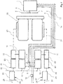
- an internal combustion engine 20 with two cylinder banks for example a V-type engine with dual-flow exhaust system and the associated exhaust-gas aftertreatment system for nitrogen oxide reduction, are shown schematically.
- a urea-water solution is provided, for example, so-called AdBlue.
- AdBlue a urea-water solution
- the tank 1 can be filled from both sides of the vehicle.
- an exhaust line 21 is present.
- the exhaust gas line 21 in each case has an injection chamber 22, in which the additive is introduced in a finely distributed manner into the exhaust gas flow via one or more nozzles.
- the exhaust gas is mixed with the additive and fed to the SCR catalyst 24.
- the exhaust gas may previously pass through a hydrolysis catalyst, not shown. From the SCR catalytic converter 24, the exhaust gas is continued via the exhaust gas outlet 25, for example to the exhaust system.
- each exhaust gas line 21 there is a delivery unit 10 and a metering unit 11 for the additive.
- the feed unit 10 sucks additive from the tank 1 and promotes him under increased pressure, usually up to max. 4 bar, to the dosing unit 11.
- the dosing unit 11 supplies the required amount of additive to the nozzle in the injection chamber 22.
- the conveyor units 10 are also still supplied with the required compressed air via a compressed air main line 30, which branches from a port on two branch lines to the two conveyor units 10.
- the required media are each provided via a common supply. This simplifies the entire system.
- the conveyor units 10 and the metering units 11 are controlled by a control unit, not shown.
- a control unit for the control, the temperature sensors 26 on the mixers and the temperature sensors 27 and the NOx sensors 28 on the SCR catalysts 24 are used. Using suitable control algorithms, the delivery and the dosage can be adapted to the operating conditions.
- the control unit is designed to also monitor the function of the various units as well as to detect and assign malfunction or failure of individual units.
- the conveyor units 10 are connected via the flow lines and the return lines to the tank 1.
- the additive is sucked in via the feed lines and the excess additive is pumped back to the tank 1 via the return lines.
- the flow lines have a common flow main line 2, which extends from the tank 1 to the distribution piece 5, and flow stub lines ranging from the distribution piece 5 to the individual conveyor units 10.
- the respective total line length of the flow of a conveyor unit 10, composed of main line and stub, is the same for the two conveyor units.
- the common return main line 3 goes from the tank 1 to the distribution piece 4. From this distribution piece 4 lead the individual return stub lines to the two conveyor units 10th
- coolant of the internal combustion engine 20 is used as heating means for the additive lines.
- the coolant is passed through the heating means feed 13 and the heating means return 14 and controlled by the solenoid valve 12 in the amount.
- a solenoid valve in the heating medium return 14 may also be provided additionally or alternatively.
- Heating agent flow 13 and return 14 are along the additive main lines and along the stubs 2.1.2.2.3.1.3.2 (which is not shown in the diagram for reasons of clarity) out.
- At least a portion of the additive feed line 2.2.1.2.2 and a portion of the additive return line 3.3.1.3.2 and heating medium supply 13 and return 14 are bundled at least in one section and laid in a hose or pipe ,
- this hose or pipe may consist of several consecutive pieces or be interrupted.
- the individual lines for additive 2,2,1,2,2,3,3.1,3.2 and for heating means 13,14 usually have an outer diameter of 5 to 10 mm.
- the tube or tube then has an outer diameter of 30 to 50 mm.
- a trunk group of four lines are formed or a trunk group of six lines, by connecting both a section of both the flow and return main line and a pair of stubs,
- the flow and return stub for one of the conveyor units 10 are included in the bundle.
- the cables can be laid easier during assembly.
- they are thus more robust overall, which also offers advantages in fire protection.
- Preference is given to at least one part, particularly preferably the predominant part, ie more than 50%, of the additive lines 2 and 3 within a supporting structure, especially laid within a support frame of the vehicle. As a result, the lines or the trunk group are better protected again.
- Fig.2 again shows a schematic section of the wiring of an exhaust aftertreatment system. Identical parts are provided with the same reference numerals. Especially shown are the stub lines of the additive lines. Starting from the distribution piece 5, the two flow stub lines 2.1 and 2.2 are the same length. And also the two return stubs 3.1 and 3.2 to the distribution piece 4 are the same length in this embodiment. As a result, equal pressure conditions are ensured at the two conveyor units, not shown here.
Landscapes
- Engineering & Computer Science (AREA)
- Chemical & Material Sciences (AREA)
- Combustion & Propulsion (AREA)
- Mechanical Engineering (AREA)
- General Engineering & Computer Science (AREA)
- Chemical Kinetics & Catalysis (AREA)
- Health & Medical Sciences (AREA)
- Toxicology (AREA)
- Exhaust Gas After Treatment (AREA)
Description
- Die Erfindung betrifft ein Abgasnachbehandlungssystem zur Stickoxidreduzierung mittels SCR (selektive katalytische Reduktion) für ein Fahrzeug mit einem Verbrennungsmotor. Das Abgasnachbehandlungssystem umfasst mindestens zwei Abgasstränge, die jeweils einen SCR-Katalysator und stromaufwärts von diesem jeweils eine Zusatzstoff-Eindüsungskammer enthalten, und einen Zusatzstoff-Tank, der diese Eindüsungskammern versorgt. Weiterhin betrifft die Erfindung auch ein Fahrzeug mit einem solchen Abgasnachbehandlungssystem.
- Als Zusatzstoff für den SCR-Prozess hat sich Harnstoff-Wasser-Lösung bewährt, wie sie beispielsweise unter dem Markennamen AdBlue vertrieben wird. Der aus der Harnstoff-Wasser-Lösung im Prozess gebildete Ammoniak führt in Verbindung mit dem SCR-Katalysator zur Reduzierung der Stickoxide im Abgas. Generell ist auch die Verwendung eines anderen Zusatzstoffes, der im Prozess Ammoniak bildet, möglich. Aus
EP 2255078 A1 ist ein solches Abgasnachbehandlungssystem bekannt, bei dem aus einem Tank zwei Eindüsungskammern in zwei Abgassträngen versorgt werden. Problematisch bei einem solchen System ist es, dass nur sehr aufwändig oder gegebenenfalls unzuverlässig für eine gleichmäßige Dosierung des Zusatzstoffes in den beiden Abgassträngen und damit für eine gute Emissionsreduzierung gesorgt werden kann. - Die Druckschrift
DE 112013000286 T5 offenbart einen Motor mit mehreren Abgassträngen und einem Abgasbehandlungssystem, bei dem Harnstofflösung in zwei entsprechende Mischleitungen eingespritzt wird. - In der Druckschrift
US 2013/343959 A1 wird eine mehrflutige Abgasanlage mit zwei Einspritzsystemen zur Abgasbehandlung gezeigt. In beiden Einspritzsystemen für die Abgasbehandlungsflüssigkeit ist jeweils eine Pumpe zur Versorgung der Common Rail für die Injektoren vorgesehen. - Auch die Druckschrift
EP 2131020 A2 beschreibt ein Abgasnachbehandlungssystem für eine zweiflutige Abgasanlage und eine dafür vorgesehene Zusatzstoff-Dosierung in jeden der Abgasstränge. Die gewünschte Dosierung wird dabei über entsprechend angesteuerte, volumetrische Dosierpumpen erreicht.
Die Aufgabe der Erfindung ist es, ein kompaktes und zuverlässigeres Abgasnachbehandlungssystem, das eine effektive Emissionsreduzierung bietet, zu entwickeln.
Die Aufgabe wird für das Abgasnachbehandlungssystem erfindungsgemäß dadurch gelöst, dass an jedem dieser Abgasstränge je eine zugeordnete Zusatzstoff-Dosiereinheit und je eine zugeordnete Zusatzstoff-Fördereinheit, die die Dosiereinheit mit Zusatzstoff auf erhöhtem Druckniveau versorgt, vorhanden sind und dass diese Fördereinheiten jeweils über eine Vorlauf-Leitung mit dem Zusatzstoff-Tank verbunden sind, wobei die jeweiligen Vorlauf-Leitungen zu den Fördereinheiten im Wesentlichen die gleiche Leitungslänge haben und wobei für eine Druckluft-Versorgung der Fördereinheiten eine gemeinsame Druckluft-Hauptleitung vorhanden ist, die sich auf Stichleitungen verzweigt und darüber die Fördereinheiten versorgt. - Der Vorteil dieser Anordnung ist, dass bei gleicher Leitungslänge zwischen den Fördereinheiten keine unterschiedlichen Ansaugdrücke vorliegen können, da die Druckverluste im Wesentlichen gleich sind. Die Fördereinheiten können somit in gleicher Weise den Zusatzstoff mit erhöhtem Druck den jeweiligen Dosiereinheiten zuführen, die diesen über die Einspritzdüse in der Eindüsungskammer dem Abgas des jeweiligen Abgasstranges zumischen. Da die Vorbedingungen an den Fördereinheiten systembedingt immer vergleichbar sind, ist eine zuverlässige auf den jeweiligen Bedarf im Abgasstrang abgestimmte Dosierung möglich.
- Weitere vorteilhafte Merkmale der erfindungsgemäßen Ausführung, die die Zuverlässigkeit oder die Kompaktheit des Systems zusätzlich verbessern, finden sich in den Unteransprüchen.
- Es ist von Vorteil, wenn die Vorlauf-Leitungen zu den jeweiligen Fördereinheiten eine gemeinsame Vorlauf-Hauptleitung und jeweils eine Vorlauf-Stichleitung je Fördereinheit aufweisen. Bevorzugt beträgt die Länge der Vorlauf-Hauptleitung in Bezug zur gesamten Leitungslänge der Vorlaufleitung (vom Zusatzstoff-Tank bis zur Fördereinheit) mindestens 50%, besonders bevorzugt mindestens 70%. Dadurch ist zum einen eine einfache Montage möglich und zum anderen ist der Einfluss der unterschiedlichen Stichleitungen auf den Ansaugdruck an den Fördereinheiten minimiert, wodurch Unterschiede im Förderverhalten und im Dosierverhalten reduziert werden.
- In einer weiteren vorteilhaften Ausführung sind die Fördereinheiten jeweils über eine Rücklauf-Leitung mit dem Zusatzstoff-Tank verbunden, wobei die jeweiligen Rücklauf-Leitungen zu den Fördereinheiten im Wesentlichen die gleiche Leitungslänge haben. Dadurch dass der Überschuss an Zusatzstoff über die Rücklauf-Leitungen zum Tank zurückgeführt wird, kann eine immer ausreichende Versorgung der Dosiereinheiten gewährleistet werden. Dadurch dass auch diese Rücklaufleitungen gleich lang sind und somit gleichen Druckverlust darstellen.
- Auch bei den Rücklauf-Leitungen wirkt es sich positiv aus, wenn eine gemeinsame Rücklauf-Hauptleitung und jeweils eine Rücklauf-Stichleitung je Fördereinheit (10) vorhanden sind und wenn in bevorzugter Ausführung die Rücklauf-Hauptleitung mindestens 50%, besonders bevorzugt mindestens 70% der Leitungslänge der gesamten Länge einer Rücklauf-Leitung vom Fördermodul bis zum Tank ausmacht.
- Um eine einfach Montage und eine erhöhte Zuverlässigkeit bei niedrigen Umgebungstemperaturen zu ermöglichen, verläuft in einer weiteren Ausführungsform zumindest ein Abschnitt der Vorlaufleitung und zumindest ein Abschnitt der Rücklaufleitung zusammen mit zumindest einer Heizmittelleitung gebündelt in einem oder mehreren hintereinander angeordneten Schläuchen oder Rohren. Dadurch dass die genannten Leitungen in einem Schlauch oder Rohr gebündelt werden, lassen sie sich einfacher verlegen und gleichzeitig ist gewährleistet, dass die Heizleitung nach an den Zusatzstoffleitungen verläuft. Zusätzlich erhöht sich auch die Robustheit der Anordnung, da die Leitungen nicht so leicht beschädigt werden können. Bevorzugt beträgt die gebündelte Länge mindestens 50%, besonders bevorzugt mindestens 70% der gesamten Vorlaufleitungslänge.
- In einer besonders vorteilhaften Ausführung verlaufen in einem Abschnitt sowohl die Vorlauf-Hauptleitung und die Rücklauf-Hauptleitung als auch eine der Vorlauf-Stichleitungen und eine der Rücklauf-Stichleitungen gebündelt in einem dieser Schläuche oder Rohre. Dadurch ergeben sich noch weniger Leitungsbündel, die verlegt werden müssen.
- Durch die Verlegung dieser Schläuche oder Rohre mit den gebündelten Leitungen können somit die Leitungen zwischen Tank und den Fördereinheiten recht kompakt installiert und im Bedarfsfall auch zuverlässig beheizt werden.
- Um die Anlage möglich kostengünstig auszuführen ist es von Vorteil, wenn für die SCR-Katalysatoren gleiche Gehäuse verwendet werden, insbesondere können Gehäuse verwendet werden, die auf beiden Seiten Montagemöglichkeiten für Sensoren aufweisen. So können trotz gleichem Gehäuse in beiden Abgassträngen die nötigen NOx- oder Temperatursensoren jeweils auf der geschützten Innenseite eingesetzt werden. Die außenliegenden Montagestellen werden einfach verschlossen.
- Besondere Vorteile bietet das System insbesondere bei Schienenfahrzeugen mit größeren Motoren. Durch die zuverlässige Dosierung in die verschiedenen Abgasstränge können bei größeren Motoren mehrere kleinere SCR-Katalysatoren verwendet werden, wie sie in einflutigen Abgasanlagen von Fahrzeugen mit kleineren Motoren, beispielsweise bei Nutzkraftwagen eingesetzt werden. Das ist insgesamt günstiger als eine großen SCR-Katalysator für den gesamten Abgasstrom einzusetzen.
- Die Zuverlässigkeit bei kalten Umgebungstemperaturen kann erhöht werden, wenn zumindest eine Heizmittelleitung vorhanden ist, die entlang der Vorlauf-Hauptleitung und der Rücklauf-Hauptleitung verläuft, wobei die Heizmittelleitung bevorzugt eine elektrische Heizleitung oder eine Motorkühlmittelleitung ist. Außerdem können die Vorlauf-Stichleitungen und die Rücklaufstichleitungen, sowie die Fördereinheiten und die Dosiereinheiten beheizbar ausgeführt sein. Durch beide Maßnahmen kann das gesamte Zuführsystem beheizt werden.
- Weiterhin können der Zusatzstofftank und vorhandene Tankleitungen beheizbar ausgeführt sein. Damit kann die Bevorratung und die Betankung für den Betrieb bei kalten Temperaturen zuverlässig gemacht werden.
- Insbesondere für Schienenfahrzeuge ist es von Vorteil, wenn der Zusatzstoff-Tank von beiden Seiten des Fahrzeuges befüllt werden kann. Dazu können zwei Tankleitungen vorgesehen werde, bevorzugt münden die beiden Tankleitungen über ein Verteilstück in eine gemeinsame Tankleitung, die zum Zusatzstoff-Tank führt.
Bevorzugt werden die Fördereinheiten und die Dosiereinheiten von einer im Abgasnachbehandlungssystem vorhandenen Steuereinheit geregelt. Von dieser Steuereinheit werden die Signale von NOx-Sensoren und gegebenenfalls auch von Temperatursensoren berücksichtig die in den Abgassträngen oder an den SCR-Katalysatoren vorhandenen sind. Ebenso kann diese Steuereinheit so ausgeführt sein, dass sie Ausfälle oder Fehlfunktionen der verschiedenen Einheiten im System detektieren und zuordnen kann. - Wichtig für die Funktion der Fördereinheiten ist die Druckluftversorgung. Um das System kompakter und die Montage einfacher zu machen, erfolgt diese Druckluft-Versorgung über eine gemeinsame Druckluft-Hauptleitung, die sich auf Stichleitungen aufteilt und die jeweiligen Fördereinheiten darüber versorgt.
Für ein Fahrzeug umfassend einen Verbrennungsmotor mit mindestens zwei Zylinderbänken, wobei jeder Zylinderbank ein Abgasstrang zugeordnet ist, wird die Aufgabe erfindungsgemäß dadurch gelöst das ein erfindungsgemäßes Abgasnachbehandlungssystem wie zuvor beschrieben vorgesehen wird.
Weiterhin ist es vorteilhaft, um die Kompaktheit und Robustheit des Systems zu erhöhen, wenn zumindest der überwiegende Anteil der Vorlauf-Hauptleitung und der Rücklauf-Hauptleitung innerhalb einer Tragstruktur, insbesondere innerhalb eines Tragrahmens des Fahrzeuges verläuft, beispielsweise im Querschnitt eines Tragholmes. Bevorzugt ist dieser Anteil der Vorlauf-Hauptleitung und der Rücklauf-Hauptleitung zusammen mit zumindest einer Heizmittelleitung in einem oder mehreren hintereinander angeordneten Schläuchen oder Rohren gebündelt. Somit kann das Leitungsbündel einfacher montiert und im Betrieb zuverlässig geheizt werden. - Anhand von Ausführungsbeispielen werden weitere vorteilhafte Ausprägungen der Erfindung erläutert unter Bezugnahme auf die Zeichnungen. Die genannten Merkmale können nicht nur in der dargestellten Kombination vorteilhaft umgesetzt werden, sondern auch einzeln untereinander kombiniert werden. Die Figuren zeigen im Einzelnen:
- Fig.1
- Schema eines erfindungsgemäßes Abgasnachbehandlungssystems an einem Verbrennungsmotor
- Fig.2
- Ausschnitt aus einem Schema zur Darstellung der Leitungsführung
- Nachfolgend werden die Figuren detaillierter beschrieben. In
Fig.1 ist ein Verbrennungsmotor 20 mit zwei Zylinderbänken, beispielsweise ein V-Motor, mit zweiflutiger Abgasführung und dem dazugehörigen Abgasnachbehandlungssystem zur Stickoxidreduzierung schematisch dargestellt. Andere Elemente zur Abgasreinigung, die vorhanden sein können, wie beispielsweise Partikelfilter, sind in der Figur weggelassen. In dem Zusatzstoff-Tank 1 wird eine Harnstoff-Wasser-Lösung bereitgestellt, beispielsweise sogenanntes AdBlue. Über eine erste Tankleitung 6 oder eine zweite Tankleitung 7, die in eine gemeinsame Tankleitung 8 münden, kann der Tank 1 von beiden Seiten des Fahrzeuges befüllt werden. - Je Zylinderbank ist ein Abgasstrang 21 vorhanden. Der Abgasstrang 21 weist jeweils eine Eindüsungskammer 22 auf, in der über eine oder mehrere Düsen der Zusatzstoff feinverteilt in den Abgasstrom eingebracht wird. In einem nachfolgenden Mischer 23 wird das Abgas mit dem Zusatzstoff durchmischt und dem SCR-Katalysator 24 zugeführt. Optional kann das Abgas zuvor noch einen nicht dargestellten Hydrolyse-Katalysator durchlaufen. Aus dem SCR-Katalysator 24 wird das Abgas über den Abgasauslass 25 weitergeführt, beispielsweise zur Auspuffanlage.
- Zu jedem Abgasstrang 21 gibt es eine Fördereinheit 10 und eine Dosiereinheit 11 für den Zusatzstoff. Die Fördereinheit 10 saugt Zusatzstoff aus dem Tank 1 an und fördert ihn unter erhöhtem Druck, üblicherweise bis max. 4 bar, zur Dosiereinheit 11. Die Dosiereinheit 11 führt die benötigte Zusatzstoffmenge der Düse in der Eindüsungskammer 22 zu. Die Fördereinheiten 10 werden zudem noch mit der benötigten Druckluft über eine Druckluft-Hauptleitung 30, die sich von einem Anschluss aus auf zwei Stichleitungen zu den beiden Fördereinheiten 10 verzweigt, versorgt. Trotz der getrennten Förder- und Dosiereinheiten für die zwei Abgasstränge 21 werden die benötigten Medien jeweils über eine gemeinsame Versorgung bereitgestellt. Das vereinfacht das gesamte System.
- Die Fördereinheiten 10 und die Dosiereinheiten 11 werden von einer nicht dargestellten Steuereinheit geregelt. Für die Regelung werden die Temperatursensoren 26 an den Mischern und die Temperatursensoren 27 und die NOx-Sensoren 28 an den SCR-Katalysatoren 24 verwendet. Über geeignete Regelalgorithmen kann die Förderung und die Dosierung an die Betriebsbedingungen angepasst werden. Die Steuereinheit ist so ausgeführt, dass sie auch die Funktion der verschiedenen Einheiten überwachen, sowie Fehlfunktionen oder Ausfälle einzelner Einheiten detektieren und zuordnen kann.
- Die Fördereinheiten 10 sind über die Vorlauf-Leitungen und über die Rücklauf-Leitungen mit dem Tank 1 verbunden. Über die Vorlauf-Leitungen wird der Zusatzstoff angesaugt und über die Rücklauf-Leitungen wir der überschüssige Zusatzstoff zum Tank 1 zurückgepumpt. Dadurch ist ein stabiler Betrieb der Fördereinheiten möglich. Die Vorlauf-Leitungen weisen eine gemeinsame Vorlauf-Hauptleitung 2, die vom Tank 1 bis zum Verteilstück 5 reicht, und Vorlauf-Stichleitungen die vom Verteilstück 5 bis zu den einzelnen Fördereinheiten 10 reichen. Die jeweilige Gesamtleitungslänge des Vorlaufes einer Fördereinheit 10, zusammengesetzt aus Hauptleitung und Stichleitung, ist für die beiden Fördereinheiten gleich. Dadurch herrschen gleiche Ansaugbedingungen für die Fördereinheiten, was die Regelung vereinfacht und die Funktion stabilisiert. Die gemeinsame Rücklauf-Hauptleitung 3 geht vom Tank 1 bis zum Verteilstück 4. Von diesem Verteilstück 4 führen die einzelnen Rücklauf-Stichleitungen zu den beiden Fördereinheiten 10.
- In der gezeigten Ausführung wird Kühlmittel des Verbrennungsmotors 20 als Heizmittel für die Zusatzstoff-Leitungen verwendet. Das Kühlmittel wird durch den Heizmittel-Vorlauf 13 und den Heizmittel-Rücklauf 14 geleitet und über das Magnetventil 12 in der Menge gesteuert. Anders als in der dargestellten Variante, bei der das Magnetventil 12 im Heizmittel-Vorlauf 13 vorgesehen ist, kann auch zusätzlich oder alternativ ein Magnetventil im Heizmittel-Rücklauf 14 vorgesehen sein. Heizmittel-Vorlauf 13 und -Rücklauf 14 werden entlang der Zusatzstoff-Hauptleitungen und entlang der Stichleitungen 2.1,2.2,3.1,3.2 (was im Schema aus Übersichtlichkeitsgründen nicht dargestellt ist) geführt.
- In einer bevorzugten Ausführung werden zumindest ein Teil der Zusatzstoff-Vorlaufleitung 2,2.1,2.2 und ein Teil der Zusatzstoff-Rücklaufleitung 3,3.1,3.2 sowie Heizmittel-Vorlauf 13 und -Rücklauf 14 wenigstens in einem Abschnitt gebündelt und in einem Schlauch oder Rohr verlegt. Gegebenenfalls kann dieser Schlauch oder das Rohr auch aus mehreren aufeinanderfolgenden Stücken bestehen bzw. unterbrochen sein. Die einzelnen Leitungen für Zusatzstoff 2,2.1,2.2,3,3.1,3.2 und für Heizmittel 13,14 haben üblicherweise einen Außendurchmesser von 5 bis 10 mm. Der Schlauch oder das Rohr hat dann einen Außendurchmesser von 30 bis 50 mm.
- So kann ein Leitungsbündel aus vier Leitungen (Zusatzstoff-Vorlauf und -Rücklauf und Heizmittel-Vorlauf und -Rücklauf) gebildet werden oder ein Leitungsbündel aus sechs Leitungen, indem über einen Abschnitt sowohl die Vorlauf- und Rücklauf-Hauptleitung als auch ein Paar der Stichleitungen, zum Beispiel die Vorlauf- und Rücklauf-Stichleitung für eine der Fördereinheiten 10, mit in das Bündel aufgenommen werden. Durch die Bündelung in einem Schlauch oder Rohr lassen sich die Leitungen bei der Montage einfacher verlegen. Zudem sind sie dadurch insgesamt robuster, was auch Vorteile beim Brandschutz bietet. Bevorzugt ist zumindest ein Teil, besonders bevorzugt der überwiegende Teil, d.h. mehr als 50%, der Zusatzstoff-Leitungen 2 und 3 innerhalb einer Tragstruktur, insbesondere innerhalb eines Tragrahmens des Fahrzeuges verlegt. Dadurch sind die Leitungen bzw. das Leitungsbündel nochmals besser geschützt.
-
Fig.2 zeigt wiederum schematisch einen Ausschnitt mit der Leitungsführung eines Abgasnachbehandlungssystems. Gleiche Teile sind mit gleichen Bezugszeichen versehen. Besonders dargestellt sind die Stichleitungen der Zusatzstoff-Leitungen. Ausgehend vom Verteilstück 5 sind die beiden Vorlauf-Stichleitungen 2.1 und 2.2 gleich lang. Und auch die beiden Rücklauf-Stichleitungen 3.1 und 3.2 bis zum Verteilstück 4 sind in dieser Ausführung gleich lang. Dadurch sind gleiche Druckverhältnisse an den beiden hier nicht dargestellten Fördereinheiten gewährleistet. -
- 1
- Zusatzstoff-Tank
- 2
- Vorlauf-Hauptleitung
- 2.1
- erste Vorlauf-Stichleitung
- 2.2
- zweite Vorlauf-Stichleitung
- 3
- Rücklauf-Hauptleitung
- 3.1
- erste Rücklauf-Stichleitung
- 3.2
- zweite Rücklauf-Stichleitung
- 4
- Verteilstück Rücklauf
- 5
- Verteilstück Vorlauf
- 6
- erste Tankleitung
- 7
- zweite Tankleitung
- 8
- gemeinsame Tankleitung
- 10
- Fördereinheit
- 11
- Dosiereinheit
- 12
- Magnetventil
- 13
- Heizmittel-Vorlauf
- 14
- Heizmittel-Rücklauf
- 20
- Verbrennungsmotor
- 21
- Abgasstrang
- 22
- Eindüsungskammer
- 23
- Mischer
- 24
- SCR-Katalysator
- 25
- Abgasauslass
- 26, 27
- Temperatursensor
- 28
- NOx-Sensor
- 30
- Druckluft-Leitung
Claims (14)
- Abgasnachbehandlungssystem zur Stickoxidreduzierung mittels SCR für ein Fahrzeug mit einem Verbrennungsmotor umfassend mindestens zwei Abgasstränge (21), die jeweils einen SCR-Katalysator (24) und stromaufwärts von diesem jeweils eine Zusatzstoff-Eindüsungskammer (22) enthalten, und einen Zusatzstoff-Tank (1), der diese Eindüsungskammern (22) versorgt,
wobei an jedem dieser Abgasstränge (21) je eine zugeordnete Zusatzstoff-Dosiereinheit (11) und je eine zugeordnete Zusatzstoff-Fördereinheit (10), die die Dosiereinheit (11) mit Zusatzstoff auf erhöhtem Druckniveau versorgt, vorhanden sind und dass diese Fördereinheiten (10) jeweils über eine Vorlauf-Leitung (2 +2.1, 2+2.2) mit dem Zusatzstoff-Tank (1) verbunden sind, wobei die jeweiligen Vorlauf-Leitungen (2+2.1, 2+2.2) zu den Fördereinheiten (10) im Wesentlichen die gleiche Leitungslänge haben.
dadurch gekennzeichnet,
dass für reine Druckluft-Versorgung der Fördereinheiten (10) eine gemeinsame Druckluft-Hauptleitung (30) vorhanden ist, die sich auf Stichleitungen verzweigt und darüber die Fördereinheiten (10) versorgt. - Abgasnachbehandlungssystem nach Anspruch 1
dadurch gekennzeichnet,
dass die Vorlauf-Leitungen (2+2.1, 2+2.2) eine gemeinsame Vorlauf-Hauptleitung (2) und jeweils eine Vorlauf-Stichleitung (2.1,2.2) je Fördereinheit (10) aufweisen. - Abgasnachbehandlungssystem nach Anspruch 1 oder 2
dadurch gekennzeichnet,
dass die Fördereinheiten (10) jeweils über eine Rücklauf-Leitung (3+3.1, 3+3.2) mit dem Zusatzstoff-Tank (1) verbunden sind, wobei die jeweiligen Rücklauf-Leitungen (3+3.1, 3+3.2) zu den Fördereinheiten (10) im Wesentlichen die gleiche Leitungslänge haben. - Abgasreinigungssystem nach einem der vorherigen Ansprüche
dadurch gekennzeichnet,
dass die Rücklauf-Leitungen (3+3.1, 3+3.2) eine gemeinsame Rücklauf-Hauptleitung (3) und jeweils eine Rücklauf-Stichleitung (3.1,3.2) je Fördereinheit (10) aufweisen. - Abgasnachbehandlungssystem nach einem der vorherigen Ansprüche
dadurch gekennzeichnet,
dass zumindest ein Abschnitt der Vorlaufleitung (2,2.1,2.2) und zumindest ein Abschnitt der Rücklaufleitung (3,3.1,3.2) zusammen mit zumindest einer Heizmittelleitung (13,14) in einem oder mehreren hintereinander angeordneten Schläuchen oder Rohren gebündelt verlaufen, wobei die gebündelte Länge bevorzugt mindestens 50%, besonders bevorzugt mindestens 70% der gesamten Vorlaufleitungslänge (2+2.1+2.2) ausmacht. - Abgasnachbehandlungssystem nach Anspruch 5
dadurch gekennzeichnet,
dass in einem Abschnitt sowohl die Vorlauf-Hauptleitung (2) und die Rücklauf-Hauptleitung (3) als auch eine der Vorlauf-Stichleitungen (2.1,2.2) und eine der Rücklauf-Stichleitungen (3.1,3.2) gebündelt in einem dieser Schläuche oder Rohre verlaufen. - Abgasnachbehandlungssystem nach einem der vorherigen Ansprüche
dadurch gekennzeichnet,
dass die SCR-Katalysatoren (24) jeweils das gleiche Gehäuse aufweisen. - Abgasnachbehandlungssystem nach einem der vorherigen Ansprüche
dadurch gekennzeichnet,
dass zumindest eine Heizmittelleitung vorhanden ist, die entlang der Vorlauf-Hauptleitung (2) und der Rücklauf-Hauptleitung (3) verläuft, wobei die Heizmittelleitung bevorzugt eine elektrische Heizleitung oder eine Motorkühlmittelleitung ist. - Abgasnachbehandlungssystem nach einem der vorherigen Ansprüche
dadurch gekennzeichnet,
dass die Vorlauf-Stichleitungen (2.1,2.2) und die Rücklaufstichleitungen (3.1,3.2), sowie die Fördereinheiten (10) und die Dosiereinheiten (11) beheizbar ausgeführt sind. - Abgasnachbehandlungssystem nach einem der vorherigen Ansprüche
dadurch gekennzeichnet,
dass der Zusatzstofftank (1) und vorhandene Tankleitungen (6,7,8) beheizbar ausgeführt sind. - Abgasnachbehandlungssystem nach einem der vorherigen Ansprüche
dadurch gekennzeichnet,
dass zwei Tankleitungen (6,7) vorhanden sind, die derart angeordnet sind, dass eine Betankung des Zusatzstoff-Tanks (1) von beiden Seiten des Fahrzeuges möglich ist, insbesondere münden die beiden Tankleitungen (6,7) über ein Verteilstück in eine gemeinsame Tankleitung (8), die zum Zusatzstoff-Tank (1) führt. - Abgasnachbehandlungssystem nach einem der vorherigen Ansprüche
dadurch gekennzeichnet,
dass eine Steuereinheit vorhanden ist, die die Fördereinheiten (10) und die Dosiereinheiten (11) regelt, wobei die Signale von an den SCR-Katalysatoren (24) jeweils vorhandenen NOx-Sensoren (28) berücksichtigt werden. - Fahrzeug umfassend einen Verbrennungsmotor mit mindestens zwei Zylinderbänken, wobei jeder Zylinderbank ein Abgasstrang zugeordnet ist, und umfassend ein Abgasnachbehandlungssystem nach einem der vorherigen Ansprüche vorhanden ist.
- Fahrzeug nach Anspruch 13
dadurch gekennzeichnet,
dass zumindest der überwiegende Anteil der Vorlaufleitung (2,2.1,2.2) und der Rücklaufleitung (3,3.1,3.2) innerhalb einer Tragstruktur, insbesondere innerhalb eines Tragrahmens des Fahrzeuges verläuft und bevorzugt dass dieser Anteil der Vorlaufleitung und der Rücklaufleitung zusammen mit zumindest einer Heizmittelleitung (13,14) in einem oder mehreren hintereinander angeordneten Schläuchen oder Rohren gebündelt verlaufen.
Priority Applications (2)
| Application Number | Priority Date | Filing Date | Title |
|---|---|---|---|
| EP18203022.1A EP3467279B1 (de) | 2014-09-22 | 2015-08-28 | Abgasnachbehandlungssystem für verbrennungsmotoren |
| PL15756400T PL3198121T3 (pl) | 2014-09-22 | 2015-08-28 | Układ wtórnego oczyszczania spalin dla silników o spalaniu wewnętrznym |
Applications Claiming Priority (2)
| Application Number | Priority Date | Filing Date | Title |
|---|---|---|---|
| DE102014219061.4A DE102014219061A1 (de) | 2014-09-22 | 2014-09-22 | Abgasnachbehandlungssystem für Verbrennungsmotoren |
| PCT/EP2015/069735 WO2016045908A1 (de) | 2014-09-22 | 2015-08-28 | Abgasnachbehandlungssystem für verbrennungsmotoren |
Related Child Applications (2)
| Application Number | Title | Priority Date | Filing Date |
|---|---|---|---|
| EP18203022.1A Division EP3467279B1 (de) | 2014-09-22 | 2015-08-28 | Abgasnachbehandlungssystem für verbrennungsmotoren |
| EP18203022.1A Division-Into EP3467279B1 (de) | 2014-09-22 | 2015-08-28 | Abgasnachbehandlungssystem für verbrennungsmotoren |
Publications (2)
| Publication Number | Publication Date |
|---|---|
| EP3198121A1 EP3198121A1 (de) | 2017-08-02 |
| EP3198121B1 true EP3198121B1 (de) | 2019-01-02 |
Family
ID=54011721
Family Applications (2)
| Application Number | Title | Priority Date | Filing Date |
|---|---|---|---|
| EP18203022.1A Active EP3467279B1 (de) | 2014-09-22 | 2015-08-28 | Abgasnachbehandlungssystem für verbrennungsmotoren |
| EP15756400.6A Active EP3198121B1 (de) | 2014-09-22 | 2015-08-28 | Abgasnachbehandlungssystem für verbrennungsmotoren |
Family Applications Before (1)
| Application Number | Title | Priority Date | Filing Date |
|---|---|---|---|
| EP18203022.1A Active EP3467279B1 (de) | 2014-09-22 | 2015-08-28 | Abgasnachbehandlungssystem für verbrennungsmotoren |
Country Status (6)
| Country | Link |
|---|---|
| EP (2) | EP3467279B1 (de) |
| CN (1) | CN106687670A (de) |
| DE (1) | DE102014219061A1 (de) |
| ES (1) | ES2716960T3 (de) |
| PL (1) | PL3198121T3 (de) |
| WO (1) | WO2016045908A1 (de) |
Families Citing this family (3)
| Publication number | Priority date | Publication date | Assignee | Title |
|---|---|---|---|---|
| DE102016215722A1 (de) | 2016-08-22 | 2018-02-22 | Bayerische Motoren Werke Aktiengesellschaft | Kraftfahrzeug-Fluidleitung mit einer umhüllenden Heizeinrichtung, insbesondere für eine wässrige Harnstofflösung |
| CN111971111B (zh) * | 2018-02-27 | 2022-08-30 | 埃克森美孚化学专利公司 | 用于将受控量的氨传送到氨消耗装置的系统和方法 |
| DE102018219851A1 (de) * | 2018-11-20 | 2020-05-20 | Robert Bosch Gmbh | Abgasnachbehandlungseinrichtung |
Citations (1)
| Publication number | Priority date | Publication date | Assignee | Title |
|---|---|---|---|---|
| US20130343959A1 (en) * | 2012-06-21 | 2013-12-26 | Tenneco Automotive Operating Company Inc. | Common rail reductant injection system |
Family Cites Families (6)
| Publication number | Priority date | Publication date | Assignee | Title |
|---|---|---|---|---|
| DE10300298A1 (de) * | 2003-01-02 | 2004-07-15 | Daimlerchrysler Ag | Abgasnachbehandlungseinrichtung und -verfahren |
| JP4657074B2 (ja) * | 2005-10-12 | 2011-03-23 | トヨタ自動車株式会社 | 排気浄化装置の制御装置及び排気浄化装置の制御方法 |
| DE202008017331U1 (de) | 2008-02-27 | 2009-06-04 | Bombardier Transportation Gmbh | Schienenfahrzeuge mit Abgasreinigung |
| GB2460825A (en) * | 2008-06-06 | 2009-12-16 | Delphi Tech Inc | Reagent dosing system |
| US8596049B2 (en) * | 2009-12-22 | 2013-12-03 | Caterpillar Inc. | Exhaust system having an aftertreatment module |
| US9476337B2 (en) * | 2012-07-05 | 2016-10-25 | Komatsu Ltd. | Engine unit and work vehicle |
-
2014
- 2014-09-22 DE DE102014219061.4A patent/DE102014219061A1/de not_active Withdrawn
-
2015
- 2015-08-28 WO PCT/EP2015/069735 patent/WO2016045908A1/de not_active Ceased
- 2015-08-28 ES ES15756400T patent/ES2716960T3/es active Active
- 2015-08-28 CN CN201580051148.0A patent/CN106687670A/zh active Pending
- 2015-08-28 PL PL15756400T patent/PL3198121T3/pl unknown
- 2015-08-28 EP EP18203022.1A patent/EP3467279B1/de active Active
- 2015-08-28 EP EP15756400.6A patent/EP3198121B1/de active Active
Patent Citations (1)
| Publication number | Priority date | Publication date | Assignee | Title |
|---|---|---|---|---|
| US20130343959A1 (en) * | 2012-06-21 | 2013-12-26 | Tenneco Automotive Operating Company Inc. | Common rail reductant injection system |
Also Published As
| Publication number | Publication date |
|---|---|
| EP3467279B1 (de) | 2019-12-11 |
| WO2016045908A1 (de) | 2016-03-31 |
| ES2716960T3 (es) | 2019-06-18 |
| PL3198121T3 (pl) | 2019-07-31 |
| DE102014219061A1 (de) | 2016-03-24 |
| EP3198121A1 (de) | 2017-08-02 |
| EP3467279A1 (de) | 2019-04-10 |
| CN106687670A (zh) | 2017-05-17 |
Similar Documents
| Publication | Publication Date | Title |
|---|---|---|
| DE102007047918B4 (de) | Abgasreinigungssystem | |
| EP3660287B1 (de) | Abgasnachbehandlungssystem sowie verfahren zur abgasnachbehandlung eines verbrennungsmotors | |
| EP2802754B1 (de) | Motorblock-anordnung mit einem abgassystem | |
| EP2010768B1 (de) | Beheizbares schlauchleitungssystem für abgasnachbehandlungsanlagen von brennkraftmaschinen | |
| EP3495707B1 (de) | Fluidleitung, verwendung einer solchen zum transport einer harnstofflösung und verfahren zur vermeidung des risikos einer beschädigung einer einspritzanordnung eines dieselmotors durch einfrierende harnstofflösung | |
| DE112015002023B4 (de) | Sensorplatte für ein Einzeleinheit-Nachbehandlungssystem | |
| WO2005024196A1 (de) | Abgasnachbehandlungseinrichtung für dieselmotoren von fahrzeugen, vorzugsweise von pkws | |
| EP2126298B1 (de) | Vorrichtung zum dosieren eines reduktionsmittels | |
| EP3467279B1 (de) | Abgasnachbehandlungssystem für verbrennungsmotoren | |
| DE102019131256A1 (de) | Abgasnachbehandlungssystem mit einem oxidationskomponentenbypass für niedrigtemperatur-scr | |
| EP2636862B1 (de) | Fördereinheit für ein flüssiges Additiv sowie Verfahren zum Betrieb dieser Fördereinheit | |
| EP3486444A1 (de) | Verfahren zur abgasnachbehandlung eines verbrennungsmotors | |
| DE102015102003A1 (de) | Mittellinieneinspritzung für Nur-Flüssigkeits-Reduktionsmittelabgabe | |
| DE102018102111A1 (de) | Vorrichtung und Verfahren zur Abgasnachbehandlung eines Verbrennungsmotors | |
| EP2564041B1 (de) | Vorrichtung zur förderung von reduktionsmittel | |
| EP2414646B1 (de) | Einspritzeinrichtung für harnstoffwasserlösung | |
| DE102012006249A1 (de) | Fördereinheit für ein flüssiges Additiv mit einem Temperatursensor | |
| DE102012018141B4 (de) | SCR-Modul | |
| EP3212906B1 (de) | Fördereinheit zur förderung einer flüssigkeit | |
| DE102011087288A1 (de) | Abgasnachbehandlungssystem und Verfahren zum Einbringen eines Reduktionsmittels in einen Abgaskanal einer Brennkraftmaschine | |
| DE102013225256B4 (de) | Fahrzeug | |
| DE102015217926A1 (de) | Vorrichtung und Verfahren zum Beheizen des Inhalts eines Reduktionsmitteltanks | |
| DE102022128485A1 (de) | Verfahren zum Betreiben eines Abgasnachbehandlungssystems sowie Abgasnachbehandlungssystem | |
| DE102014212892A1 (de) | Filtereinheit | |
| DE102021004145A1 (de) | Abgasanlage für eine Verbrennungskraftmaschine eines Kraftfahrzeugs |
Legal Events
| Date | Code | Title | Description |
|---|---|---|---|
| STAA | Information on the status of an ep patent application or granted ep patent |
Free format text: STATUS: THE INTERNATIONAL PUBLICATION HAS BEEN MADE |
|
| PUAI | Public reference made under article 153(3) epc to a published international application that has entered the european phase |
Free format text: ORIGINAL CODE: 0009012 |
|
| STAA | Information on the status of an ep patent application or granted ep patent |
Free format text: STATUS: REQUEST FOR EXAMINATION WAS MADE |
|
| 17P | Request for examination filed |
Effective date: 20170424 |
|
| AK | Designated contracting states |
Kind code of ref document: A1 Designated state(s): AL AT BE BG CH CY CZ DE DK EE ES FI FR GB GR HR HU IE IS IT LI LT LU LV MC MK MT NL NO PL PT RO RS SE SI SK SM TR |
|
| AX | Request for extension of the european patent |
Extension state: BA ME |
|
| DAV | Request for validation of the european patent (deleted) | ||
| DAX | Request for extension of the european patent (deleted) | ||
| STAA | Information on the status of an ep patent application or granted ep patent |
Free format text: STATUS: EXAMINATION IS IN PROGRESS |
|
| 17Q | First examination report despatched |
Effective date: 20180420 |
|
| GRAP | Despatch of communication of intention to grant a patent |
Free format text: ORIGINAL CODE: EPIDOSNIGR1 |
|
| STAA | Information on the status of an ep patent application or granted ep patent |
Free format text: STATUS: GRANT OF PATENT IS INTENDED |
|
| INTG | Intention to grant announced |
Effective date: 20180807 |
|
| GRAS | Grant fee paid |
Free format text: ORIGINAL CODE: EPIDOSNIGR3 |
|
| GRAA | (expected) grant |
Free format text: ORIGINAL CODE: 0009210 |
|
| STAA | Information on the status of an ep patent application or granted ep patent |
Free format text: STATUS: THE PATENT HAS BEEN GRANTED |
|
| AK | Designated contracting states |
Kind code of ref document: B1 Designated state(s): AL AT BE BG CH CY CZ DE DK EE ES FI FR GB GR HR HU IE IS IT LI LT LU LV MC MK MT NL NO PL PT RO RS SE SI SK SM TR |
|
| REG | Reference to a national code |
Ref country code: GB Ref legal event code: FG4D Free format text: NOT ENGLISH |
|
| REG | Reference to a national code |
Ref country code: CH Ref legal event code: EP Ref country code: AT Ref legal event code: REF Ref document number: 1084659 Country of ref document: AT Kind code of ref document: T Effective date: 20190115 |
|
| REG | Reference to a national code |
Ref country code: IE Ref legal event code: FG4D Free format text: LANGUAGE OF EP DOCUMENT: GERMAN |
|
| REG | Reference to a national code |
Ref country code: DE Ref legal event code: R096 Ref document number: 502015007528 Country of ref document: DE |
|
| REG | Reference to a national code |
Ref country code: NL Ref legal event code: MP Effective date: 20190102 |
|
| REG | Reference to a national code |
Ref country code: LT Ref legal event code: MG4D |
|
| REG | Reference to a national code |
Ref country code: ES Ref legal event code: FG2A Ref document number: 2716960 Country of ref document: ES Kind code of ref document: T3 Effective date: 20190618 |
|
| PG25 | Lapsed in a contracting state [announced via postgrant information from national office to epo] |
Ref country code: NL Free format text: LAPSE BECAUSE OF FAILURE TO SUBMIT A TRANSLATION OF THE DESCRIPTION OR TO PAY THE FEE WITHIN THE PRESCRIBED TIME-LIMIT Effective date: 20190102 |
|
| PG25 | Lapsed in a contracting state [announced via postgrant information from national office to epo] |
Ref country code: PT Free format text: LAPSE BECAUSE OF FAILURE TO SUBMIT A TRANSLATION OF THE DESCRIPTION OR TO PAY THE FEE WITHIN THE PRESCRIBED TIME-LIMIT Effective date: 20190502 Ref country code: NO Free format text: LAPSE BECAUSE OF FAILURE TO SUBMIT A TRANSLATION OF THE DESCRIPTION OR TO PAY THE FEE WITHIN THE PRESCRIBED TIME-LIMIT Effective date: 20190402 Ref country code: SE Free format text: LAPSE BECAUSE OF FAILURE TO SUBMIT A TRANSLATION OF THE DESCRIPTION OR TO PAY THE FEE WITHIN THE PRESCRIBED TIME-LIMIT Effective date: 20190102 Ref country code: LT Free format text: LAPSE BECAUSE OF FAILURE TO SUBMIT A TRANSLATION OF THE DESCRIPTION OR TO PAY THE FEE WITHIN THE PRESCRIBED TIME-LIMIT Effective date: 20190102 Ref country code: FI Free format text: LAPSE BECAUSE OF FAILURE TO SUBMIT A TRANSLATION OF THE DESCRIPTION OR TO PAY THE FEE WITHIN THE PRESCRIBED TIME-LIMIT Effective date: 20190102 |
|
| PG25 | Lapsed in a contracting state [announced via postgrant information from national office to epo] |
Ref country code: HR Free format text: LAPSE BECAUSE OF FAILURE TO SUBMIT A TRANSLATION OF THE DESCRIPTION OR TO PAY THE FEE WITHIN THE PRESCRIBED TIME-LIMIT Effective date: 20190102 Ref country code: RS Free format text: LAPSE BECAUSE OF FAILURE TO SUBMIT A TRANSLATION OF THE DESCRIPTION OR TO PAY THE FEE WITHIN THE PRESCRIBED TIME-LIMIT Effective date: 20190102 Ref country code: BG Free format text: LAPSE BECAUSE OF FAILURE TO SUBMIT A TRANSLATION OF THE DESCRIPTION OR TO PAY THE FEE WITHIN THE PRESCRIBED TIME-LIMIT Effective date: 20190402 Ref country code: IS Free format text: LAPSE BECAUSE OF FAILURE TO SUBMIT A TRANSLATION OF THE DESCRIPTION OR TO PAY THE FEE WITHIN THE PRESCRIBED TIME-LIMIT Effective date: 20190502 Ref country code: LV Free format text: LAPSE BECAUSE OF FAILURE TO SUBMIT A TRANSLATION OF THE DESCRIPTION OR TO PAY THE FEE WITHIN THE PRESCRIBED TIME-LIMIT Effective date: 20190102 Ref country code: GR Free format text: LAPSE BECAUSE OF FAILURE TO SUBMIT A TRANSLATION OF THE DESCRIPTION OR TO PAY THE FEE WITHIN THE PRESCRIBED TIME-LIMIT Effective date: 20190403 |
|
| REG | Reference to a national code |
Ref country code: DE Ref legal event code: R097 Ref document number: 502015007528 Country of ref document: DE |
|
| PG25 | Lapsed in a contracting state [announced via postgrant information from national office to epo] |
Ref country code: EE Free format text: LAPSE BECAUSE OF FAILURE TO SUBMIT A TRANSLATION OF THE DESCRIPTION OR TO PAY THE FEE WITHIN THE PRESCRIBED TIME-LIMIT Effective date: 20190102 Ref country code: DK Free format text: LAPSE BECAUSE OF FAILURE TO SUBMIT A TRANSLATION OF THE DESCRIPTION OR TO PAY THE FEE WITHIN THE PRESCRIBED TIME-LIMIT Effective date: 20190102 Ref country code: AL Free format text: LAPSE BECAUSE OF FAILURE TO SUBMIT A TRANSLATION OF THE DESCRIPTION OR TO PAY THE FEE WITHIN THE PRESCRIBED TIME-LIMIT Effective date: 20190102 Ref country code: RO Free format text: LAPSE BECAUSE OF FAILURE TO SUBMIT A TRANSLATION OF THE DESCRIPTION OR TO PAY THE FEE WITHIN THE PRESCRIBED TIME-LIMIT Effective date: 20190102 Ref country code: CZ Free format text: LAPSE BECAUSE OF FAILURE TO SUBMIT A TRANSLATION OF THE DESCRIPTION OR TO PAY THE FEE WITHIN THE PRESCRIBED TIME-LIMIT Effective date: 20190102 |
|
| PLBE | No opposition filed within time limit |
Free format text: ORIGINAL CODE: 0009261 |
|
| STAA | Information on the status of an ep patent application or granted ep patent |
Free format text: STATUS: NO OPPOSITION FILED WITHIN TIME LIMIT |
|
| PG25 | Lapsed in a contracting state [announced via postgrant information from national office to epo] |
Ref country code: SM Free format text: LAPSE BECAUSE OF FAILURE TO SUBMIT A TRANSLATION OF THE DESCRIPTION OR TO PAY THE FEE WITHIN THE PRESCRIBED TIME-LIMIT Effective date: 20190102 |
|
| RAP2 | Party data changed (patent owner data changed or rights of a patent transferred) |
Owner name: VOITH PATENT GMBH |
|
| 26N | No opposition filed |
Effective date: 20191003 |
|
| PG25 | Lapsed in a contracting state [announced via postgrant information from national office to epo] |
Ref country code: SI Free format text: LAPSE BECAUSE OF FAILURE TO SUBMIT A TRANSLATION OF THE DESCRIPTION OR TO PAY THE FEE WITHIN THE PRESCRIBED TIME-LIMIT Effective date: 20190102 |
|
| PG25 | Lapsed in a contracting state [announced via postgrant information from national office to epo] |
Ref country code: TR Free format text: LAPSE BECAUSE OF FAILURE TO SUBMIT A TRANSLATION OF THE DESCRIPTION OR TO PAY THE FEE WITHIN THE PRESCRIBED TIME-LIMIT Effective date: 20190102 |
|
| PG25 | Lapsed in a contracting state [announced via postgrant information from national office to epo] |
Ref country code: MC Free format text: LAPSE BECAUSE OF FAILURE TO SUBMIT A TRANSLATION OF THE DESCRIPTION OR TO PAY THE FEE WITHIN THE PRESCRIBED TIME-LIMIT Effective date: 20190102 Ref country code: LU Free format text: LAPSE BECAUSE OF NON-PAYMENT OF DUE FEES Effective date: 20190828 |
|
| REG | Reference to a national code |
Ref country code: BE Ref legal event code: MM Effective date: 20190831 |
|
| PG25 | Lapsed in a contracting state [announced via postgrant information from national office to epo] |
Ref country code: IE Free format text: LAPSE BECAUSE OF NON-PAYMENT OF DUE FEES Effective date: 20190828 |
|
| PG25 | Lapsed in a contracting state [announced via postgrant information from national office to epo] |
Ref country code: BE Free format text: LAPSE BECAUSE OF NON-PAYMENT OF DUE FEES Effective date: 20190831 |
|
| PG25 | Lapsed in a contracting state [announced via postgrant information from national office to epo] |
Ref country code: CY Free format text: LAPSE BECAUSE OF FAILURE TO SUBMIT A TRANSLATION OF THE DESCRIPTION OR TO PAY THE FEE WITHIN THE PRESCRIBED TIME-LIMIT Effective date: 20190102 |
|
| PG25 | Lapsed in a contracting state [announced via postgrant information from national office to epo] |
Ref country code: HU Free format text: LAPSE BECAUSE OF FAILURE TO SUBMIT A TRANSLATION OF THE DESCRIPTION OR TO PAY THE FEE WITHIN THE PRESCRIBED TIME-LIMIT; INVALID AB INITIO Effective date: 20150828 Ref country code: MT Free format text: LAPSE BECAUSE OF FAILURE TO SUBMIT A TRANSLATION OF THE DESCRIPTION OR TO PAY THE FEE WITHIN THE PRESCRIBED TIME-LIMIT Effective date: 20190102 |
|
| PG25 | Lapsed in a contracting state [announced via postgrant information from national office to epo] |
Ref country code: MK Free format text: LAPSE BECAUSE OF FAILURE TO SUBMIT A TRANSLATION OF THE DESCRIPTION OR TO PAY THE FEE WITHIN THE PRESCRIBED TIME-LIMIT Effective date: 20190102 |
|
| PGFP | Annual fee paid to national office [announced via postgrant information from national office to epo] |
Ref country code: IT Payment date: 20230825 Year of fee payment: 9 Ref country code: GB Payment date: 20230822 Year of fee payment: 9 Ref country code: CH Payment date: 20230902 Year of fee payment: 9 Ref country code: AT Payment date: 20230822 Year of fee payment: 9 |
|
| PGFP | Annual fee paid to national office [announced via postgrant information from national office to epo] |
Ref country code: SK Payment date: 20230821 Year of fee payment: 9 Ref country code: PL Payment date: 20230817 Year of fee payment: 9 Ref country code: FR Payment date: 20230825 Year of fee payment: 9 Ref country code: DE Payment date: 20230821 Year of fee payment: 9 |
|
| PGFP | Annual fee paid to national office [announced via postgrant information from national office to epo] |
Ref country code: ES Payment date: 20231027 Year of fee payment: 9 |
|
| REG | Reference to a national code |
Ref country code: DE Ref legal event code: R119 Ref document number: 502015007528 Country of ref document: DE |
|
| REG | Reference to a national code |
Ref country code: CH Ref legal event code: PL |
|
| REG | Reference to a national code |
Ref country code: SK Ref legal event code: MM4A Ref document number: E 30348 Country of ref document: SK Effective date: 20240828 |
|
| REG | Reference to a national code |
Ref country code: AT Ref legal event code: MM01 Ref document number: 1084659 Country of ref document: AT Kind code of ref document: T Effective date: 20240828 |
|
| GBPC | Gb: european patent ceased through non-payment of renewal fee |
Effective date: 20240828 |
|
| PG25 | Lapsed in a contracting state [announced via postgrant information from national office to epo] |
Ref country code: AT Free format text: LAPSE BECAUSE OF NON-PAYMENT OF DUE FEES Effective date: 20240828 Ref country code: CH Free format text: LAPSE BECAUSE OF NON-PAYMENT OF DUE FEES Effective date: 20240831 |
|
| PG25 | Lapsed in a contracting state [announced via postgrant information from national office to epo] |
Ref country code: SK Free format text: LAPSE BECAUSE OF NON-PAYMENT OF DUE FEES Effective date: 20240828 |
|
| PG25 | Lapsed in a contracting state [announced via postgrant information from national office to epo] |
Ref country code: DE Free format text: LAPSE BECAUSE OF NON-PAYMENT OF DUE FEES Effective date: 20250301 |
|
| PG25 | Lapsed in a contracting state [announced via postgrant information from national office to epo] |
Ref country code: GB Free format text: LAPSE BECAUSE OF NON-PAYMENT OF DUE FEES Effective date: 20240828 |
|
| PG25 | Lapsed in a contracting state [announced via postgrant information from national office to epo] |
Ref country code: IT Free format text: LAPSE BECAUSE OF NON-PAYMENT OF DUE FEES Effective date: 20240828 |
|
| PG25 | Lapsed in a contracting state [announced via postgrant information from national office to epo] |
Ref country code: FR Free format text: LAPSE BECAUSE OF NON-PAYMENT OF DUE FEES Effective date: 20240831 |
|
| REG | Reference to a national code |
Ref country code: ES Ref legal event code: FD2A Effective date: 20251002 |
|
| PG25 | Lapsed in a contracting state [announced via postgrant information from national office to epo] |
Ref country code: ES Free format text: LAPSE BECAUSE OF NON-PAYMENT OF DUE FEES Effective date: 20240829 |
|
| PG25 | Lapsed in a contracting state [announced via postgrant information from national office to epo] |
Ref country code: PL Free format text: LAPSE BECAUSE OF NON-PAYMENT OF DUE FEES Effective date: 20240828 |