EP3197643B1 - Werkzeugbehälteranordnung - Google Patents
Werkzeugbehälteranordnung Download PDFInfo
- Publication number
- EP3197643B1 EP3197643B1 EP15775046.4A EP15775046A EP3197643B1 EP 3197643 B1 EP3197643 B1 EP 3197643B1 EP 15775046 A EP15775046 A EP 15775046A EP 3197643 B1 EP3197643 B1 EP 3197643B1
- Authority
- EP
- European Patent Office
- Prior art keywords
- container assembly
- tool container
- indicators
- operatively connected
- extension portion
- Prior art date
- Legal status (The legal status is an assumption and is not a legal conclusion. Google has not performed a legal analysis and makes no representation as to the accuracy of the status listed.)
- Active
Links
Images


Classifications
-
- B—PERFORMING OPERATIONS; TRANSPORTING
- B25—HAND TOOLS; PORTABLE POWER-DRIVEN TOOLS; MANIPULATORS
- B25H—WORKSHOP EQUIPMENT, e.g. FOR MARKING-OUT WORK; STORAGE MEANS FOR WORKSHOPS
- B25H3/00—Storage means or arrangements for workshops facilitating access to, or handling of, work tools or instruments
- B25H3/02—Boxes
-
- B—PERFORMING OPERATIONS; TRANSPORTING
- B25—HAND TOOLS; PORTABLE POWER-DRIVEN TOOLS; MANIPULATORS
- B25H—WORKSHOP EQUIPMENT, e.g. FOR MARKING-OUT WORK; STORAGE MEANS FOR WORKSHOPS
- B25H3/00—Storage means or arrangements for workshops facilitating access to, or handling of, work tools or instruments
-
- B—PERFORMING OPERATIONS; TRANSPORTING
- B65—CONVEYING; PACKING; STORING; HANDLING THIN OR FILAMENTARY MATERIAL
- B65D—CONTAINERS FOR STORAGE OR TRANSPORT OF ARTICLES OR MATERIALS, e.g. BAGS, BARRELS, BOTTLES, BOXES, CANS, CARTONS, CRATES, DRUMS, JARS, TANKS, HOPPERS, FORWARDING CONTAINERS; ACCESSORIES, CLOSURES, OR FITTINGS THEREFOR; PACKAGING ELEMENTS; PACKAGES
- B65D25/00—Details of other kinds or types of rigid or semi-rigid containers
- B65D25/28—Handles
- B65D25/2867—Handles with respective ends fixed to local areas of two opposite sides or wall-part
Definitions
- Dropped objects such as tools and small parts could be hazardous on work sites, especially where workers are performing tasks at heights and other workers are positioned below them.
- Many workers use tool containers such as buckets or bags to transport a variety of tools, small parts, and other items to work sites. Commonly, the buckets or bags are lifted using ropes to the work sites.
- this presents a problem of potential tipping during the lifting process should the buckets or bags be top loaded or should they become snagged on structures thereby spilling the contents.
- Existing closure assemblies are difficult to operate and, therefore, workers tend to not use the closure assemblies.
- workers tend to leave tools, small parts, and other items laying on platforms, equipment, and other surfaces when not in use. This also presents a problem when the tools or small parts are accidentally bumped or otherwise moved because they could fall and injure workers positioned below the work sites.
- a tool container assembly comprises a body, an extension portion, and a fastening member.
- the body has a bottom, a side, and a top providing access to a cavity formed by the bottom and the side.
- the extension portion is operatively connected to the top, and the extension portion has a distal end portion.
- the fastening member is operatively connected to the distal end portion, and the fastening member has an open position and a closed position. The open position forms an opening allowing access to the cavity, and the closed position closes the opening thereby preventing access to the cavity.
- the closed position includes an easy opening position and a difficult opening position.
- a tool container assembly comprises a body, an extension portion, a fastening member, handles, and indicators.
- the body has a bottom, a side, and a top providing access to a cavity formed by the bottom and the side.
- the extension portion is operatively connected to the top, and the extension portion has a distal end portion.
- the fastening member is operatively connected to the distal end portion, and the fastening member has an open position and a closed position. The open position forms an opening allowing access to the cavity, and the closed position closes the opening thereby preventing access to the cavity.
- a first handle and a second handle are operatively connected to opposing sides of the distal end portion of the extension portion.
- First and third indicators are positioned on one side and second and fourth indicators are positioned on another side of the distal end portion.
- the first and second indicators are at least partially aligned to at least partially align the first and second handles and position the extension portion in an easy opening position, and the third and fourth indicators are at least partially aligned to offset the first and second handles and position the extension portion in a difficult opening position.
- a tool container assembly comprises a body, an extension portion, and a fastening member.
- the body has a bottom, a side, and a top providing access to a cavity formed by the bottom and the side.
- the extension portion is operatively connected to the top, and the extension portion has a distal end portion.
- the fastening member is operatively connected to the distal end portion, and the fastening member has an open position and a closed position. The open position forms an opening allowing access to the cavity, and the closed position closes the opening thereby preventing access to the cavity.
- the fastening member includes a drawstring and an engaging member. Friction between the engaging member and the drawstring assists in keeping the drawstring in a desired position and allows the drawstring to move through the engaging member when a force is exerted on the drawstring.
- Embodiments of the present invention generally provide a tool container assembly comprising a body, an extension portion, and a fastening member.
- the body has a bottom, a side, and a top providing access to a cavity formed by the bottom and the side.
- the extension portion is operatively connected to the top, and the extension portion has a distal end portion.
- the extension portion and the fastening member are part of the closure assembly.
- the fastening member is operatively connected to the distal end portion, and the fastening member has an open position and a closed position.
- the open position forms an opening allowing access to the cavity, and the closed position closes the opening thereby preventing access to the cavity.
- the closed position includes an easy opening position and a difficult opening position.
- the fastening member could be any suitable fastener from the group consisting of a hook and loop fastener, a plurality of snaps, a drawstring, a buckle, and other suitable fasteners.
- embodiments of the present invention generally optionally provide a tether assembly configured and arranged to interconnect tools, small parts, and other items to the tool container assembly. Further, embodiments of the present invention generally also optionally provide an insert configured and arranged to provide additional storage and organization options.
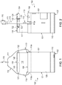
- a tool container assembly 100 includes a body 101 having a bottom 102, a side 107, and a top 108.
- the bottom 102, the side 107, and the top 108 form a cavity 109 accessible through an opening formed by the top 108.
- a rim 119 is operatively connected to the top 108 to assist in providing structure to the top 108 and its opening.
- An extension portion 117 which is a sleeve-like extension of the side 107, is operatively connected to the top 108 and includes a distal end portion 118.
- a bottom support 110 could be used to interconnect the bottom 102 and the side 107 and could be used to add strength proximate the bottom of the assembly.
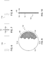
- the bottom 102 includes a first layer 103 preferably made of tarpaulin, a second layer 104 preferably made of hardboard, a third layer 105 preferably made of tarpaulin, and a fourth layer 106 preferably made of PVC leather.
- the bottom support 110 could include an inside layer 110a made of tarpaulin and an outside layer 110b made of tarpaulin.
- the bottom 102 is shown in Figures 9 and 10 . In Figure 9 , the first, third, and fourth layers 103, 105, and 106 are folded and stitched thereby hiding the third layer 105, and in Figure 10 , the first, third, and fourth layers 103, 105, and 106 are unstitched and unfolded.
- the side 107, the top 108, and the extension portion 117 are preferably made of canvas.
- the rim 119 is preferably positioned in the top hem of the side 107, and could be any suitable material such as but not limited to molded plastic, nylon pipe material, steel, or wood approximately one inch wide, which makes the top of the container relatively stiff. It is recognized that fewer or more layers made of different materials could be used for any of these components in accordance with desired durability.
- An elongate member 111 preferably made of webbing or rope includes an intermediate portion 114 interconnecting a first end 112 and a second end 113.
- a first reinforcing member 112a may be operatively connected to the side 107 proximate the top 108, and proximate an opposing side of the side 107, a second reinforcing member 113a may be operatively connected to the side 107 proximate the top 108.
- the reinforcing members 112a and 113a provide stronger areas to which the ends 112 and 113 are connected.
- the reinforcing members 112a and 113a may be made of a stronger material, such as leather, and include apertures through which the respective ends 112 and 113 are inserted and then secured onto themselves, preferably by stitching or any other suitable securing member, forming loops through which the rim 119 extends.
- a connector 115 for example a carabiner, may be connected to the intermediate portion 114 to provide a way to connect the assembly to a hoist line, an anchorage structure, or the like.
- a first handle 121 is operatively connected to a first outer side of the distal end portion 118, and a second handle 122 is operatively connected to a second, generally opposing outer side of the distal end portion 118.
- the handles 121 and 122 are connected to the respective sides with handle attachments 123, in this embodiment box-X stitch patterns, having inner sides 123a relative to the handles, as shown in Figures 3 and 5 .
- the handles 121 and 122 or the elongate member 111 could be used to carry the assembly.
- a fastening member 124 interconnects first and second inner sides of the distal end portion 118.
- a loop portion 125 is operatively connected to one inner side and a hook portion 126 is operatively connected to a generally opposing inner side.
- the distal end portion 118 forms an opening, which may be positioned in an open position or a closed position (not shown in this embodiment).
- the opening In the open position, the opening provides access to the cavity 109.
- the closed position In the closed position, the opening is generally closed by the fastening member 124 thereby preventing access to the cavity 109.
- the distal end portion 118 also includes indicators, which assist in positioning the distal end portion 118 in the desired closed position.
- a first pair of indicators are aligned for the easy opening position and a second pair of indicators are aligned for the difficult opening position.
- a first indicator 131 is proximate a first end of the first handle 121
- a second indicator 132 is proximate a first end of the second handle 122
- a third indicator 133 is proximate a second end of the first handle 121
- a fourth indicator 134 is positioned a distance away from a second end of the second handle 122. It is recognized that other suitable types of indicators could be used.
- An optional attachment member 136 includes an engaging portion 137, which is preferably a ring or a hook to which any suitable tool lanyard may be connected, and a strap 138, which is preferably nylon webbing or an elastic material and interconnects the engaging portion 137 and the body 101, preferably the inside surface of the side 107.
- the attachment member 136 is shown in Figure 3 .
- tool container assembly 100' shown in Figure 11 the closure assembly and additional features are described, but substantially similar features to the tool container assembly 100 are not described.
- the elongate member 111' could be a cord or rope with a knot or stop 111a' proximate each end preventing the ends from sliding through the respective apertures in the reinforcement members 112a' and 113a', preferably positioned below the rim 119'.
- the optional attachment member 136' includes an engaging portion, which is preferably a ring or a hook to which any suitable tool lanyard may be connected, and a strap, which is preferably nylon webbing or an elastic material and interconnects the engaging portion and the body, preferably the inside surface of the side.
- the attachment member 136' is shown in Figure 11 and extends generally downward rather than upward as the attachment member 136.
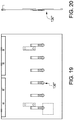
- Another embodiment attachment member 136" is shown in Figures 19 and 20 .
- the distal end 118' of the extension portion 117' includes the handles 121' and 122' and the fastening member 124', including the loop portion 125' and the hook portion 126', similar to the tool container assembly 100, and the two closed positions 129a' and 129b' are shown in Figures 12-15 .
- the easy opening position 129a' is shown in Figures 12 and 14
- the difficult opening position 129b' is shown in Figures 13 and 15 .
- the first and second indicators 131' and 132' are each a first colored tab
- the third and fourth indicators 133' and 134' are each a second colored tab.
- the first colored tabs could be green, indicating the easy opening position 129a'
- the second colored tabs could be red, indicating the difficult opening position 129b'.
- the ends of the first and second handles 121' and 122' are at least partially aligned or overlapping, including the handle attachments securing the ends of the handles to the distal end portion 118' (in this embodiment the box-X stitch patterns). It is preferred in this embodiment that the inner sides of the handle attachments relative to the handles are within 1.50 inches from one another, when positioned in either right or left positions relative to one another, in the easy opening position 129a'.
- the first and second handles 121' and 122' are not at least partially aligned or overlapping.
- this arrangement is preferred in this embodiment, it is recognized that any arrangement where the inner sides of the handle attachments relative to the handles are greater than 1.50 inches from one another position the assembly in the difficult opening position 129b'. This positions the fastening member 124' in a difficult opening position 129b' because leverage using one's hands cannot pull the handles 121' and 122', and thereby the fastening member 124', apart.
- the user places her/his fingers in the gaps 130' formed between the opposing sides to force the loop and hook portions 125' and 126' of the fastening member 124' apart.
- These two different closed positions are beneficial during different circumstances. For example, during transit, it may be desirable to position the fastening member 124' in the difficult opening position 129b' to prevent accidental opening of the assembly resulting in spilling its contents and, during use, it may be desirable to position the fastening member 124' in the easy opening position 129a' to allow easy access to the contents while preventing spillage of the contents while performing tasks.
- the fastening member 124' is difficult to separate, making it difficult to breach, which is particularly useful as the user lifts or travels with the container at elevation without the risk of spilling the items stored inside the container.
- the first and second indicators are separated, the handle attachments are not at least partially aligned or overlapping, and the fastening member 124' creates a stronger connection thereby making it difficult to open the closure system by simply using the handles, which are also not directly opposite one another, but are offset, relative to one another. This contributes to the difficulty of opening the closure system.
- the user is required to peel from the corners or ends of the closure system proximate the top in order to separate and open the closure. This provides a secure method for lifting and transporting the container while securing the contents inside.
- an optional insert 140 could also be used with any of the embodiments.
- the insert 140 is configured and arranged to fit within the cavity 109 and includes a support member 141, which is preferably made of hardboard or any other suitable semi-rigid to rigid material.
- the support member 141 is generally rectangular in shape with a first end 142 to which a first fastener (e.g., hook portion) 143 is connected and a second end 144 to which a second fastener (e.g., loop portion) 145 is connected.
- a plurality of pockets 146 made of nylon or other suitable material, are operatively connected.
- the plurality of pockets 146 could include gusset portions 147 and binder material 148.
- the plurality of pockets 146 could be positioned to either face inside or outside relative to the support member 141.
- the insert 140 allows for additional items to be organized within the body's cavity 109.
- Tool container assembly 200 includes a body 201 having a bottom 202, a side 207, and a top 208.
- the bottom 202, the side 207, and the top 208 form a cavity 209 accessible through an opening formed by the top 208.
- a rim 219 is operatively connected to the top 208 to assist in providing structure to the top 208 and its opening.
- An extension portion 217 which is a sleeve-like extension of the side 207, is operatively connected to the top 208 and includes a distal end portion 218, which in this embodiment is folded over onto itself and secured by stitching to form a channel 218a.
- a bottom support 210 could be used to interconnect the bottom 202 and the side 207 and could be used to add strength proximate the bottom of the assembly.
- the bottom 202 could be similar to the bottom 102 and include several layers, and the bottom support 210 could include an inside layer and an outside layer.
- the side 207, the top 208, and the extension portion 217 could also be made of canvas.
- the rim 219 is preferably positioned in the top hem of the side 207, and could be any suitable material such as but not limited to molded plastic, nylon pipe material, steel, or wood approximately one inch wide, which makes the top of the container relatively stiff. It is recognized that fewer or more layers made of different materials could be used for any of these components in accordance with desired durability.
- An elongate member 211 preferably made of webbing or rope includes an intermediate portion 214 interconnecting a first end 212 and a second end 213.
- a first reinforcing member 212a may be operatively connected to the side 207 proximate the top 208, and proximate an opposing side of the side 207, a second reinforcing member 213a may be operatively connected to the side 207 proximate the top 208.
- the reinforcing members 212a and 213a provide stronger areas to which the ends 212 and 213 are connected.
- the reinforcing members 212a and 213a may be made of a stronger material, such as leather, and include apertures through which the respective ends 212 and 213 are inserted and then secured onto themselves, preferably by stitching or any other suitable securing member, forming loops through which the rim 219 extends.
- a connector 215, for example a carabiner, may be connected to the intermediate portion 214 to provide a way to connect the assembly to a hoist line, an anchorage structure, or the like.
- a first handle 221 is operatively connected to a first outer side of the distal end portion 218, and a second handle 222 is operatively connected to a second, generally opposing outer side of the distal end portion 218.
- the handles 221 and 222 or the elongate member 211 could be used to carry the assembly.
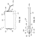
- a fastening member 224 in this embodiment includes a drawstring 225, which is routed through the channel 218a through an opening providing access to the channel 218a proximate the first handle 221.
- the ends of the drawstring 225 extend outward through the opening and are operatively connected to the first handle 221 and the extension portion 217 via an engaging member 226.
- the engaging member 226 is a sleeve forming two channels through which the ends are routed, and the distal ends of the drawstring 225 are secured together with a stop member 225a. Stitching secures the engaging member 226 to the first handle 221 and the extension portion 217 between the two channels.
- the two channels are configured and arranged to provide friction on the drawstring 225 so that a desired amount of force is needed to move the drawstring 225 through the engaging member 226.
- the fastening member 224 also includes a locking member 231, which includes a hook member 232 and a ring member 233.
- the hook member 232 is operatively connected to the first handle 221, and the ring member 233 is operatively connected to the second handle 222.
- the fastening member 224 is used to position an opening 228 formed by the distal end portion 218 of the extension portion 217 between an open position 227, illustrated in Figure 30 , and a closed position. There are two closed positions, an easy opening position (not shown) and a difficult opening position 229b, illustrated in Figure 31 .
- the opening In the open position, the opening provides access to the cavity 209.
- the closed position In the closed position, the opening is generally closed by the fastening member 224 thereby preventing access to the cavity 209.
- the drawstring 225 is pulled to reduce the amount of drawstring 225 within the channel 218a thereby gathering or cinching the top of the extension portion 217.
- the reduced opening may form a relatively small gap 230. Friction between the engaging member 226 and the drawstring 225 assist in preventing the drawstring 225 from moving through the engaging member 226 with little to no force exerted upon the assembly. This is the easy opening position.
- the hook member 232 engages the ring member 233, as shown in Figure 31 .
- the hook member 232 is disconnected from the ring member 233.
- the user may either insert a finger from each hand proximate opposing sides of the gap 230 and pull, or the user may pull the handles 221 and 222 away from each other.
- An optional attachment member 236 includes an engaging portion 237, which is preferably a ring or a hook to which any suitable tool lanyard may be connected, and a strap 238, which is preferably nylon webbing or an elastic material and interconnects the engaging portion 237 and the body 201, preferably the inside surface of the side 207.
- the attachment member 236 is shown in Figures 27 and 28 .
- the various features of the embodiments could be interchangeable, and the embodiments offer flexibility in materials depending upon desired style and durability.
- the body of the tool container assembly could be made of a variety of materials, and examples of materials include canvas, duck canvas, vinyl, nylon, polyester, synthetic leather, leather, material with or without UV resistance, FR rated material, and material used for extreme weather. In addition, these materials could be any desired thickness and weight.
- the bottom of the tool container assembly could include a hard-body material placed on top of the exterior material to add stiffness to the bottom and prevent puncture should a sharp or pointed object be thrown into the container. An interior material could be placed on top of the hard-body material to keep the hard-body material sandwiched between the exterior and interior materials.
- the exterior and interior materials could be any suitable material such as those listed for the body of the tool container assembly.
- the elongate member which is generally a lifting strap, is preferably a nylon webbing material but other suitable materials such as polyester webbing, cord, rope, leather, and other suitable materials could be used.
- the lifting strap is used to lift the assembly using the connector, which could be a hook, ring, or other suitable connector.
- the connector could be made of aluminum, steel, stainless steel, or other suitable material.
- the connector could be optional.
Landscapes
- Engineering & Computer Science (AREA)
- Mechanical Engineering (AREA)
- Details Of Rigid Or Semi-Rigid Containers (AREA)
- Purses, Travelling Bags, Baskets, Or Suitcases (AREA)
- Workshop Equipment, Work Benches, Supports, Or Storage Means (AREA)
- Bag Frames (AREA)
Claims (12)
- Werkzeugbehälterbaugruppe (100), umfassend:einen Körper (101) mit einem Boden (102), einer Seite (107) und einer Oberseite (108), die Zugang zu einem Hohlraum (109) bietet, der durch den Boden und die Seite gebildet wird;einen Verlängerungsabschnitt (117), der funktional mit der Oberseite verbunden ist, wobei der Verlängerungsabschnitt einen distalen Endabschnitt aufweist;ein Verschlusselement (124), das funktional mit dem distalen Endabschnitt (118) verbunden ist, wobei das Verschlusselement eine offene Position und eine geschlossene Position aufweist, wobei die offene Position eine Öffnung bildet, die den Zugang zum Hohlraum ermöglicht, wobei die geschlossene Position die Öffnung schließt und dadurch den Zugang zum Hohlraum verhindert, dadurch gekennzeichnet, dass die geschlossene Position eine Position des leichten Öffnens und eine Position des schwierigen Öffnens aufweist; undein erstes Paar Indikatoren (131, 133), die auf einer Seite des distalen Endabschnitts positioniert sind, und ein zweites Paar Indikatoren (132, 134), die auf dessen anderer Seite positioniert sind, wobei die Indikatoren zumindest teilweise dazu ausgerichtet sind, den Verlängerungsabschnitt in einer der Positionen des leichten Öffnens und des schwierigen Öffnens zu positionieren.
- Werkzeugbehälterbaugruppe nach Anspruch 1, ferner umfassend ein längliches Element (111) mit einem ersten und einem zweiten Ende, die funktional mit gegenüberliegenden Seiten der Oberseite des Körpers verbunden sind.
- Werkzeugbehälterbaugruppe nach Anspruch 2, ferner umfassend einen Verbinder (115), der funktional mit einem Zwischenabschnitt des länglichen Elements verbunden ist.
- Werkzeugbehälterbaugruppe nach Anspruch 1, ferner umfassend ein Befestigungselement (136), das funktional mit der Seite und/oder dem Verlängerungsabschnitt verbunden ist.
- Werkzeugbehälterbaugruppe nach Anspruch 4, wobei das Befestigungselement (136) einen Ringabschnitt beinhaltet.
- Werkzeugbehälterbaugruppe nach Anspruch 5, wobei ein Band (138) die Seite und/oder den Verlängerungsabschnitt mit dem Ring verbindet.
- Werkzeugbehälterbaugruppe nach Anspruch 6, wobei das Band (138) aus elastischem Material hergestellt ist.
- Werkzeugbehälterbaugruppe nach Anspruch 1, wobei das Verschlusselement (124) einen Hakenabschnitt und einen Schlaufenabschnitt beinhaltet, wobei der Hakenabschnitt und der Schlaufenabschnitt funktional mit gegenüberliegenden Seiten des distalen Endabschnitts des Verlängerungsabschnitts verbunden sind.
- Werkzeugbehälterbaugruppe nach Anspruch 8, ferner umfassend einen ersten Griff (121) und einen zweiten Griff (122), wobei der erste und zweite Griff funktional mit den gegenüberliegenden Seiten des distalen Endabschnitts des Verlängerungsabschnitts verbunden sind.
- Werkzeugbehälterbaugruppe nach Anspruch 9, wobei das erste Paar Indikatoren auf einer Seite des distalen Endabschnitts einen ersten Indikator (131) und einen dritten Indikator (133) beinhaltet und das zweite Paar Indikatoren auf einer anderen Seite des distalen Endabschnitts einen zweiten Indikator und einen vierten Indikator beinhaltet, wobei der erste (131) und der zweite (132) Indikator zumindest teilweise dazu ausgerichtet sind, den Verlängerungsabschnitt in der Position des leichten Öffnens zu positionieren, wobei der dritte (133) und vierte (134) Indikator zumindest teilweise dazu ausgerichtet sind, den Verlängerungsabschnitt in der Position des schwierigen Öffnens zu positionieren.
- Werkzeugbehälterbaugruppe nach Anspruch 10, wobei der erste (131) und der zweite (132) Indikator Laschen einer ersten Farbe sind und der dritte (133) und der vierte (134) Indikator Laschen einer zweiten Farbe sind.
- Werkzeugbehälterbaugruppe nach Anspruch 1, ferner umfassend einen Einsatz (140), der so konfiguriert und angeordnet ist, dass er in den Hohlraum passt, wobei der Einsatz zumindest halbsteif ist und eine Mehrzahl von Taschen (146) umfasst.
Applications Claiming Priority (4)
| Application Number | Priority Date | Filing Date | Title |
|---|---|---|---|
| US201462053422P | 2014-09-22 | 2014-09-22 | |
| US201562101481P | 2015-01-09 | 2015-01-09 | |
| US14/858,338 US9993918B2 (en) | 2014-09-22 | 2015-09-18 | Tool container assembly |
| PCT/US2015/051176 WO2016048873A1 (en) | 2014-09-22 | 2015-09-21 | Tool container assembly |
Publications (2)
| Publication Number | Publication Date |
|---|---|
| EP3197643A1 EP3197643A1 (de) | 2017-08-02 |
| EP3197643B1 true EP3197643B1 (de) | 2020-04-22 |
Family
ID=55524898
Family Applications (1)
| Application Number | Title | Priority Date | Filing Date |
|---|---|---|---|
| EP15775046.4A Active EP3197643B1 (de) | 2014-09-22 | 2015-09-21 | Werkzeugbehälteranordnung |
Country Status (7)
| Country | Link |
|---|---|
| US (1) | US9993918B2 (de) |
| EP (1) | EP3197643B1 (de) |
| JP (1) | JP2017534470A (de) |
| CN (1) | CN106715055B (de) |
| AU (1) | AU2015321666B9 (de) |
| CA (1) | CA2962087A1 (de) |
| WO (1) | WO2016048873A1 (de) |
Families Citing this family (3)
| Publication number | Priority date | Publication date | Assignee | Title |
|---|---|---|---|---|
| WO2020170060A1 (en) * | 2019-02-20 | 2020-08-27 | 3M Innovative Properties Company | Closure system for container |
| US20220193884A1 (en) * | 2020-12-22 | 2022-06-23 | Alan Paul Byrne | Tool organizer |
| US12492522B2 (en) * | 2021-04-15 | 2025-12-09 | Bedell Property Management, LLC | System for applying snow and ice removal and traction-improving products |
Family Cites Families (13)
| Publication number | Priority date | Publication date | Assignee | Title |
|---|---|---|---|---|
| US2445265A (en) * | 1945-10-15 | 1948-07-13 | Hargrave John Edward | Detachable handle |
| US4403638A (en) * | 1982-04-21 | 1983-09-13 | Frank Baum | Combination camera bag |
| US4688674A (en) * | 1986-06-06 | 1987-08-25 | Stirtz Ronald H | Sack and rope assembly |
| US4887751A (en) | 1987-12-30 | 1989-12-19 | Michael Lehman | Traveler's organizer bag luggage |
| US5653337A (en) * | 1993-02-16 | 1997-08-05 | Cirigliano; Charles F. | Reversible tote bag |
| DE10018607A1 (de) | 2000-04-14 | 2001-10-25 | Deutsche Telekom Ag | Faltbarer Aufzieheimer bzw. -behälter |
| US6823992B2 (en) | 2002-03-20 | 2004-11-30 | Travel Caddy, Inc.. | Tool carrying and storage case |
| US7117991B2 (en) | 2003-09-03 | 2006-10-10 | Innovative Design Solutions, Inc. | Portable carrier |
| US20050211586A1 (en) | 2004-03-25 | 2005-09-29 | Fierek David P | Bucket tool organizer with tool insert |
| US20080169739A1 (en) * | 2007-01-03 | 2008-07-17 | Keter Plastic Ltd. | Carriable and wall mountable tool storage system |
| US20080197756A1 (en) | 2007-02-20 | 2008-08-21 | Eastway Fair Company Limited | Tool Bag with Attached Compartment |
| US20090250470A1 (en) * | 2008-04-04 | 2009-10-08 | Bryce Merrick | Tool Bucket |
| DE102011086874A1 (de) * | 2011-11-22 | 2013-05-23 | Robert Bosch Gmbh | Handwerkzeugkoffer |
-
2015
- 2015-09-18 US US14/858,338 patent/US9993918B2/en active Active
- 2015-09-21 CN CN201580050611.XA patent/CN106715055B/zh not_active Expired - Fee Related
- 2015-09-21 EP EP15775046.4A patent/EP3197643B1/de active Active
- 2015-09-21 CA CA2962087A patent/CA2962087A1/en not_active Abandoned
- 2015-09-21 AU AU2015321666A patent/AU2015321666B9/en not_active Ceased
- 2015-09-21 JP JP2017515803A patent/JP2017534470A/ja active Pending
- 2015-09-21 WO PCT/US2015/051176 patent/WO2016048873A1/en not_active Ceased
Non-Patent Citations (1)
| Title |
|---|
| None * |
Also Published As
| Publication number | Publication date |
|---|---|
| US20160082585A1 (en) | 2016-03-24 |
| CN106715055B (zh) | 2019-06-11 |
| JP2017534470A (ja) | 2017-11-24 |
| CA2962087A1 (en) | 2016-03-31 |
| AU2015321666B9 (en) | 2019-04-04 |
| AU2015321666A1 (en) | 2017-04-06 |
| US9993918B2 (en) | 2018-06-12 |
| CN106715055A (zh) | 2017-05-24 |
| WO2016048873A1 (en) | 2016-03-31 |
| EP3197643A1 (de) | 2017-08-02 |
| AU2015321666B2 (en) | 2018-11-15 |
Similar Documents
| Publication | Publication Date | Title |
|---|---|---|
| US12420133B2 (en) | Weighted bag | |
| US10149997B1 (en) | Weighted bag | |
| US7841635B2 (en) | Apparatus for securing and carrying a package | |
| US8016173B2 (en) | Bag for carrying concrete finishing tools | |
| US20130014792A1 (en) | Hoop shifter, parachute tent and flop clip | |
| US9259067B2 (en) | Carrying apparatus | |
| EP3197643B1 (de) | Werkzeugbehälteranordnung | |
| US9371160B2 (en) | Moving device | |
| WO2014199168A1 (en) | Improvement to an article of luggage | |
| US20170313476A1 (en) | Tool bag carrying handle with auxiliary loop | |
| US20100140970A1 (en) | Support means for assisting in hauling an item | |
| US20150021945A1 (en) | Safety sling | |
| US20110068021A1 (en) | Tow strap bag | |
| US20130126567A1 (en) | Rescue equipment bag | |
| US20220127047A1 (en) | Closure system for container | |
| GB2633556A (en) | Sleeve for transporting items | |
| US20160207742A1 (en) | Lifting device, system, and method | |
| GB2632848A (en) | Sleeve for transporting items | |
| JP5313019B2 (ja) | ランドセルの予備ベルト取付構造 | |
| WO2025040879A1 (en) | Sleeve and apparatus for transporting items | |
| DE202018003782U1 (de) | Hängematten Rucksack | |
| CZ1121U1 (cs) | Víceúčelová plážová podložka | |
| AU2009202860A1 (en) | A moving device |
Legal Events
| Date | Code | Title | Description |
|---|---|---|---|
| STAA | Information on the status of an ep patent application or granted ep patent |
Free format text: STATUS: THE INTERNATIONAL PUBLICATION HAS BEEN MADE |
|
| PUAI | Public reference made under article 153(3) epc to a published international application that has entered the european phase |
Free format text: ORIGINAL CODE: 0009012 |
|
| STAA | Information on the status of an ep patent application or granted ep patent |
Free format text: STATUS: REQUEST FOR EXAMINATION WAS MADE |
|
| 17P | Request for examination filed |
Effective date: 20170424 |
|
| AK | Designated contracting states |
Kind code of ref document: A1 Designated state(s): AL AT BE BG CH CY CZ DE DK EE ES FI FR GB GR HR HU IE IS IT LI LT LU LV MC MK MT NL NO PL PT RO RS SE SI SK SM TR |
|
| AX | Request for extension of the european patent |
Extension state: BA ME |
|
| DAV | Request for validation of the european patent (deleted) | ||
| DAX | Request for extension of the european patent (deleted) | ||
| GRAP | Despatch of communication of intention to grant a patent |
Free format text: ORIGINAL CODE: EPIDOSNIGR1 |
|
| STAA | Information on the status of an ep patent application or granted ep patent |
Free format text: STATUS: GRANT OF PATENT IS INTENDED |
|
| INTG | Intention to grant announced |
Effective date: 20191115 |
|
| GRAS | Grant fee paid |
Free format text: ORIGINAL CODE: EPIDOSNIGR3 |
|
| GRAA | (expected) grant |
Free format text: ORIGINAL CODE: 0009210 |
|
| STAA | Information on the status of an ep patent application or granted ep patent |
Free format text: STATUS: THE PATENT HAS BEEN GRANTED |
|
| AK | Designated contracting states |
Kind code of ref document: B1 Designated state(s): AL AT BE BG CH CY CZ DE DK EE ES FI FR GB GR HR HU IE IS IT LI LT LU LV MC MK MT NL NO PL PT RO RS SE SI SK SM TR |
|
| REG | Reference to a national code |
Ref country code: CH Ref legal event code: EP |
|
| REG | Reference to a national code |
Ref country code: IE Ref legal event code: FG4D |
|
| REG | Reference to a national code |
Ref country code: DE Ref legal event code: R096 Ref document number: 602015051228 Country of ref document: DE |
|
| REG | Reference to a national code |
Ref country code: AT Ref legal event code: REF Ref document number: 1259462 Country of ref document: AT Kind code of ref document: T Effective date: 20200515 |
|
| REG | Reference to a national code |
Ref country code: LT Ref legal event code: MG4D |
|
| REG | Reference to a national code |
Ref country code: NL Ref legal event code: MP Effective date: 20200422 |
|
| PG25 | Lapsed in a contracting state [announced via postgrant information from national office to epo] |
Ref country code: IS Free format text: LAPSE BECAUSE OF FAILURE TO SUBMIT A TRANSLATION OF THE DESCRIPTION OR TO PAY THE FEE WITHIN THE PRESCRIBED TIME-LIMIT Effective date: 20200822 Ref country code: LT Free format text: LAPSE BECAUSE OF FAILURE TO SUBMIT A TRANSLATION OF THE DESCRIPTION OR TO PAY THE FEE WITHIN THE PRESCRIBED TIME-LIMIT Effective date: 20200422 Ref country code: NL Free format text: LAPSE BECAUSE OF FAILURE TO SUBMIT A TRANSLATION OF THE DESCRIPTION OR TO PAY THE FEE WITHIN THE PRESCRIBED TIME-LIMIT Effective date: 20200422 Ref country code: SE Free format text: LAPSE BECAUSE OF FAILURE TO SUBMIT A TRANSLATION OF THE DESCRIPTION OR TO PAY THE FEE WITHIN THE PRESCRIBED TIME-LIMIT Effective date: 20200422 Ref country code: PT Free format text: LAPSE BECAUSE OF FAILURE TO SUBMIT A TRANSLATION OF THE DESCRIPTION OR TO PAY THE FEE WITHIN THE PRESCRIBED TIME-LIMIT Effective date: 20200824 Ref country code: GR Free format text: LAPSE BECAUSE OF FAILURE TO SUBMIT A TRANSLATION OF THE DESCRIPTION OR TO PAY THE FEE WITHIN THE PRESCRIBED TIME-LIMIT Effective date: 20200723 Ref country code: FI Free format text: LAPSE BECAUSE OF FAILURE TO SUBMIT A TRANSLATION OF THE DESCRIPTION OR TO PAY THE FEE WITHIN THE PRESCRIBED TIME-LIMIT Effective date: 20200422 Ref country code: NO Free format text: LAPSE BECAUSE OF FAILURE TO SUBMIT A TRANSLATION OF THE DESCRIPTION OR TO PAY THE FEE WITHIN THE PRESCRIBED TIME-LIMIT Effective date: 20200722 |
|
| REG | Reference to a national code |
Ref country code: AT Ref legal event code: MK05 Ref document number: 1259462 Country of ref document: AT Kind code of ref document: T Effective date: 20200422 |
|
| PG25 | Lapsed in a contracting state [announced via postgrant information from national office to epo] |
Ref country code: LV Free format text: LAPSE BECAUSE OF FAILURE TO SUBMIT A TRANSLATION OF THE DESCRIPTION OR TO PAY THE FEE WITHIN THE PRESCRIBED TIME-LIMIT Effective date: 20200422 Ref country code: HR Free format text: LAPSE BECAUSE OF FAILURE TO SUBMIT A TRANSLATION OF THE DESCRIPTION OR TO PAY THE FEE WITHIN THE PRESCRIBED TIME-LIMIT Effective date: 20200422 Ref country code: BG Free format text: LAPSE BECAUSE OF FAILURE TO SUBMIT A TRANSLATION OF THE DESCRIPTION OR TO PAY THE FEE WITHIN THE PRESCRIBED TIME-LIMIT Effective date: 20200722 Ref country code: RS Free format text: LAPSE BECAUSE OF FAILURE TO SUBMIT A TRANSLATION OF THE DESCRIPTION OR TO PAY THE FEE WITHIN THE PRESCRIBED TIME-LIMIT Effective date: 20200422 |
|
| PG25 | Lapsed in a contracting state [announced via postgrant information from national office to epo] |
Ref country code: AL Free format text: LAPSE BECAUSE OF FAILURE TO SUBMIT A TRANSLATION OF THE DESCRIPTION OR TO PAY THE FEE WITHIN THE PRESCRIBED TIME-LIMIT Effective date: 20200422 |
|
| REG | Reference to a national code |
Ref country code: DE Ref legal event code: R097 Ref document number: 602015051228 Country of ref document: DE |
|
| PG25 | Lapsed in a contracting state [announced via postgrant information from national office to epo] |
Ref country code: AT Free format text: LAPSE BECAUSE OF FAILURE TO SUBMIT A TRANSLATION OF THE DESCRIPTION OR TO PAY THE FEE WITHIN THE PRESCRIBED TIME-LIMIT Effective date: 20200422 Ref country code: EE Free format text: LAPSE BECAUSE OF FAILURE TO SUBMIT A TRANSLATION OF THE DESCRIPTION OR TO PAY THE FEE WITHIN THE PRESCRIBED TIME-LIMIT Effective date: 20200422 Ref country code: ES Free format text: LAPSE BECAUSE OF FAILURE TO SUBMIT A TRANSLATION OF THE DESCRIPTION OR TO PAY THE FEE WITHIN THE PRESCRIBED TIME-LIMIT Effective date: 20200422 Ref country code: CZ Free format text: LAPSE BECAUSE OF FAILURE TO SUBMIT A TRANSLATION OF THE DESCRIPTION OR TO PAY THE FEE WITHIN THE PRESCRIBED TIME-LIMIT Effective date: 20200422 Ref country code: RO Free format text: LAPSE BECAUSE OF FAILURE TO SUBMIT A TRANSLATION OF THE DESCRIPTION OR TO PAY THE FEE WITHIN THE PRESCRIBED TIME-LIMIT Effective date: 20200422 Ref country code: SM Free format text: LAPSE BECAUSE OF FAILURE TO SUBMIT A TRANSLATION OF THE DESCRIPTION OR TO PAY THE FEE WITHIN THE PRESCRIBED TIME-LIMIT Effective date: 20200422 Ref country code: IT Free format text: LAPSE BECAUSE OF FAILURE TO SUBMIT A TRANSLATION OF THE DESCRIPTION OR TO PAY THE FEE WITHIN THE PRESCRIBED TIME-LIMIT Effective date: 20200422 Ref country code: DK Free format text: LAPSE BECAUSE OF FAILURE TO SUBMIT A TRANSLATION OF THE DESCRIPTION OR TO PAY THE FEE WITHIN THE PRESCRIBED TIME-LIMIT Effective date: 20200422 |
|
| PG25 | Lapsed in a contracting state [announced via postgrant information from national office to epo] |
Ref country code: SK Free format text: LAPSE BECAUSE OF FAILURE TO SUBMIT A TRANSLATION OF THE DESCRIPTION OR TO PAY THE FEE WITHIN THE PRESCRIBED TIME-LIMIT Effective date: 20200422 Ref country code: PL Free format text: LAPSE BECAUSE OF FAILURE TO SUBMIT A TRANSLATION OF THE DESCRIPTION OR TO PAY THE FEE WITHIN THE PRESCRIBED TIME-LIMIT Effective date: 20200422 |
|
| PLBE | No opposition filed within time limit |
Free format text: ORIGINAL CODE: 0009261 |
|
| STAA | Information on the status of an ep patent application or granted ep patent |
Free format text: STATUS: NO OPPOSITION FILED WITHIN TIME LIMIT |
|
| 26N | No opposition filed |
Effective date: 20210125 |
|
| PG25 | Lapsed in a contracting state [announced via postgrant information from national office to epo] |
Ref country code: MC Free format text: LAPSE BECAUSE OF FAILURE TO SUBMIT A TRANSLATION OF THE DESCRIPTION OR TO PAY THE FEE WITHIN THE PRESCRIBED TIME-LIMIT Effective date: 20200422 |
|
| REG | Reference to a national code |
Ref country code: CH Ref legal event code: PL |
|
| PG25 | Lapsed in a contracting state [announced via postgrant information from national office to epo] |
Ref country code: SI Free format text: LAPSE BECAUSE OF FAILURE TO SUBMIT A TRANSLATION OF THE DESCRIPTION OR TO PAY THE FEE WITHIN THE PRESCRIBED TIME-LIMIT Effective date: 20200422 |
|
| REG | Reference to a national code |
Ref country code: BE Ref legal event code: MM Effective date: 20200930 |
|
| PG25 | Lapsed in a contracting state [announced via postgrant information from national office to epo] |
Ref country code: LU Free format text: LAPSE BECAUSE OF NON-PAYMENT OF DUE FEES Effective date: 20200921 |
|
| PG25 | Lapsed in a contracting state [announced via postgrant information from national office to epo] |
Ref country code: FR Free format text: LAPSE BECAUSE OF NON-PAYMENT OF DUE FEES Effective date: 20200930 |
|
| PG25 | Lapsed in a contracting state [announced via postgrant information from national office to epo] |
Ref country code: LI Free format text: LAPSE BECAUSE OF NON-PAYMENT OF DUE FEES Effective date: 20200930 Ref country code: IE Free format text: LAPSE BECAUSE OF NON-PAYMENT OF DUE FEES Effective date: 20200921 Ref country code: BE Free format text: LAPSE BECAUSE OF NON-PAYMENT OF DUE FEES Effective date: 20200930 Ref country code: CH Free format text: LAPSE BECAUSE OF NON-PAYMENT OF DUE FEES Effective date: 20200930 |
|
| PG25 | Lapsed in a contracting state [announced via postgrant information from national office to epo] |
Ref country code: TR Free format text: LAPSE BECAUSE OF FAILURE TO SUBMIT A TRANSLATION OF THE DESCRIPTION OR TO PAY THE FEE WITHIN THE PRESCRIBED TIME-LIMIT Effective date: 20200422 Ref country code: MT Free format text: LAPSE BECAUSE OF FAILURE TO SUBMIT A TRANSLATION OF THE DESCRIPTION OR TO PAY THE FEE WITHIN THE PRESCRIBED TIME-LIMIT Effective date: 20200422 Ref country code: CY Free format text: LAPSE BECAUSE OF FAILURE TO SUBMIT A TRANSLATION OF THE DESCRIPTION OR TO PAY THE FEE WITHIN THE PRESCRIBED TIME-LIMIT Effective date: 20200422 |
|
| PG25 | Lapsed in a contracting state [announced via postgrant information from national office to epo] |
Ref country code: MK Free format text: LAPSE BECAUSE OF FAILURE TO SUBMIT A TRANSLATION OF THE DESCRIPTION OR TO PAY THE FEE WITHIN THE PRESCRIBED TIME-LIMIT Effective date: 20200422 |
|
| PGFP | Annual fee paid to national office [announced via postgrant information from national office to epo] |
Ref country code: GB Payment date: 20220819 Year of fee payment: 8 |
|
| P01 | Opt-out of the competence of the unified patent court (upc) registered |
Effective date: 20230530 |
|
| GBPC | Gb: european patent ceased through non-payment of renewal fee |
Effective date: 20230921 |
|
| PG25 | Lapsed in a contracting state [announced via postgrant information from national office to epo] |
Ref country code: GB Free format text: LAPSE BECAUSE OF NON-PAYMENT OF DUE FEES Effective date: 20230921 |
|
| PG25 | Lapsed in a contracting state [announced via postgrant information from national office to epo] |
Ref country code: GB Free format text: LAPSE BECAUSE OF NON-PAYMENT OF DUE FEES Effective date: 20230921 |
|
| PGFP | Annual fee paid to national office [announced via postgrant information from national office to epo] |
Ref country code: DE Payment date: 20250820 Year of fee payment: 11 |