EP3197358B1 - Pulse oximeter with an accelerometer - Google Patents
Pulse oximeter with an accelerometer Download PDFInfo
- Publication number
- EP3197358B1 EP3197358B1 EP15747302.6A EP15747302A EP3197358B1 EP 3197358 B1 EP3197358 B1 EP 3197358B1 EP 15747302 A EP15747302 A EP 15747302A EP 3197358 B1 EP3197358 B1 EP 3197358B1
- Authority
- EP
- European Patent Office
- Prior art keywords
- pulse oximeter
- processor
- determining
- accelerometer
- measurement
- Prior art date
- Legal status (The legal status is an assumption and is not a legal conclusion. Google has not performed a legal analysis and makes no representation as to the accuracy of the status listed.)
- Active
Links
- 238000005259 measurement Methods 0.000 claims description 153
- 230000000694 effects Effects 0.000 claims description 68
- 238000000034 method Methods 0.000 claims description 44
- 230000004044 response Effects 0.000 claims description 33
- 230000001133 acceleration Effects 0.000 claims description 25
- QVGXLLKOCUKJST-UHFFFAOYSA-N atomic oxygen Chemical compound [O] QVGXLLKOCUKJST-UHFFFAOYSA-N 0.000 description 31
- 229910052760 oxygen Inorganic materials 0.000 description 31
- 239000001301 oxygen Substances 0.000 description 31
- 239000008280 blood Substances 0.000 description 25
- 210000004369 blood Anatomy 0.000 description 25
- 239000003990 capacitor Substances 0.000 description 17
- 238000009532 heart rate measurement Methods 0.000 description 13
- 230000033001 locomotion Effects 0.000 description 12
- 238000010586 diagram Methods 0.000 description 11
- 230000004622 sleep time Effects 0.000 description 9
- 230000006870 function Effects 0.000 description 8
- 230000001276 controlling effect Effects 0.000 description 7
- 230000008569 process Effects 0.000 description 7
- 230000002596 correlated effect Effects 0.000 description 6
- 230000001413 cellular effect Effects 0.000 description 5
- 230000002093 peripheral effect Effects 0.000 description 5
- 238000005070 sampling Methods 0.000 description 5
- 238000004891 communication Methods 0.000 description 3
- 238000013461 design Methods 0.000 description 3
- 238000012544 monitoring process Methods 0.000 description 3
- 210000000707 wrist Anatomy 0.000 description 3
- 230000005540 biological transmission Effects 0.000 description 2
- 210000000624 ear auricle Anatomy 0.000 description 2
- 238000012806 monitoring device Methods 0.000 description 2
- 230000003287 optical effect Effects 0.000 description 2
- 238000012545 processing Methods 0.000 description 2
- 230000001360 synchronised effect Effects 0.000 description 2
- 238000012546 transfer Methods 0.000 description 2
- 235000017060 Arachis glabrata Nutrition 0.000 description 1
- 241001553178 Arachis glabrata Species 0.000 description 1
- 235000010777 Arachis hypogaea Nutrition 0.000 description 1
- 235000018262 Arachis monticola Nutrition 0.000 description 1
- 238000010521 absorption reaction Methods 0.000 description 1
- 230000015556 catabolic process Effects 0.000 description 1
- 238000004590 computer program Methods 0.000 description 1
- 238000006731 degradation reaction Methods 0.000 description 1
- 238000007599 discharging Methods 0.000 description 1
- 239000000463 material Substances 0.000 description 1
- 239000002184 metal Substances 0.000 description 1
- 239000000203 mixture Substances 0.000 description 1
- 238000012986 modification Methods 0.000 description 1
- 230000004048 modification Effects 0.000 description 1
- 235000020232 peanut Nutrition 0.000 description 1
- 230000035790 physiological processes and functions Effects 0.000 description 1
- APTZNLHMIGJTEW-UHFFFAOYSA-N pyraflufen-ethyl Chemical compound C1=C(Cl)C(OCC(=O)OCC)=CC(C=2C(=C(OC(F)F)N(C)N=2)Cl)=C1F APTZNLHMIGJTEW-UHFFFAOYSA-N 0.000 description 1
Images


Classifications
-
- A—HUMAN NECESSITIES
- A61—MEDICAL OR VETERINARY SCIENCE; HYGIENE
- A61B—DIAGNOSIS; SURGERY; IDENTIFICATION
- A61B5/00—Measuring for diagnostic purposes; Identification of persons
- A61B5/145—Measuring characteristics of blood in vivo, e.g. gas concentration, pH value; Measuring characteristics of body fluids or tissues, e.g. interstitial fluid, cerebral tissue
- A61B5/1455—Measuring characteristics of blood in vivo, e.g. gas concentration, pH value; Measuring characteristics of body fluids or tissues, e.g. interstitial fluid, cerebral tissue using optical sensors, e.g. spectral photometrical oximeters
- A61B5/14551—Measuring characteristics of blood in vivo, e.g. gas concentration, pH value; Measuring characteristics of body fluids or tissues, e.g. interstitial fluid, cerebral tissue using optical sensors, e.g. spectral photometrical oximeters for measuring blood gases
-
- A—HUMAN NECESSITIES
- A61—MEDICAL OR VETERINARY SCIENCE; HYGIENE
- A61B—DIAGNOSIS; SURGERY; IDENTIFICATION
- A61B5/00—Measuring for diagnostic purposes; Identification of persons
- A61B5/103—Detecting, measuring or recording devices for testing the shape, pattern, colour, size or movement of the body or parts thereof, for diagnostic purposes
- A61B5/11—Measuring movement of the entire body or parts thereof, e.g. head or hand tremor, mobility of a limb
- A61B5/1118—Determining activity level
-
- A—HUMAN NECESSITIES
- A61—MEDICAL OR VETERINARY SCIENCE; HYGIENE
- A61B—DIAGNOSIS; SURGERY; IDENTIFICATION
- A61B5/00—Measuring for diagnostic purposes; Identification of persons
- A61B5/145—Measuring characteristics of blood in vivo, e.g. gas concentration, pH value; Measuring characteristics of body fluids or tissues, e.g. interstitial fluid, cerebral tissue
- A61B5/1455—Measuring characteristics of blood in vivo, e.g. gas concentration, pH value; Measuring characteristics of body fluids or tissues, e.g. interstitial fluid, cerebral tissue using optical sensors, e.g. spectral photometrical oximeters
- A61B5/14551—Measuring characteristics of blood in vivo, e.g. gas concentration, pH value; Measuring characteristics of body fluids or tissues, e.g. interstitial fluid, cerebral tissue using optical sensors, e.g. spectral photometrical oximeters for measuring blood gases
- A61B5/14552—Details of sensors specially adapted therefor
-
- A—HUMAN NECESSITIES
- A61—MEDICAL OR VETERINARY SCIENCE; HYGIENE
- A61B—DIAGNOSIS; SURGERY; IDENTIFICATION
- A61B5/00—Measuring for diagnostic purposes; Identification of persons
- A61B5/68—Arrangements of detecting, measuring or recording means, e.g. sensors, in relation to patient
- A61B5/6801—Arrangements of detecting, measuring or recording means, e.g. sensors, in relation to patient specially adapted to be attached to or worn on the body surface
- A61B5/6813—Specially adapted to be attached to a specific body part
- A61B5/6825—Hand
- A61B5/6826—Finger
-
- A—HUMAN NECESSITIES
- A61—MEDICAL OR VETERINARY SCIENCE; HYGIENE
- A61B—DIAGNOSIS; SURGERY; IDENTIFICATION
- A61B5/00—Measuring for diagnostic purposes; Identification of persons
- A61B5/68—Arrangements of detecting, measuring or recording means, e.g. sensors, in relation to patient
- A61B5/6801—Arrangements of detecting, measuring or recording means, e.g. sensors, in relation to patient specially adapted to be attached to or worn on the body surface
- A61B5/683—Means for maintaining contact with the body
- A61B5/6832—Means for maintaining contact with the body using adhesives
- A61B5/6833—Adhesive patches
-
- A—HUMAN NECESSITIES
- A61—MEDICAL OR VETERINARY SCIENCE; HYGIENE
- A61B—DIAGNOSIS; SURGERY; IDENTIFICATION
- A61B5/00—Measuring for diagnostic purposes; Identification of persons
- A61B5/72—Signal processing specially adapted for physiological signals or for diagnostic purposes
- A61B5/7203—Signal processing specially adapted for physiological signals or for diagnostic purposes for noise prevention, reduction or removal
- A61B5/7207—Signal processing specially adapted for physiological signals or for diagnostic purposes for noise prevention, reduction or removal of noise induced by motion artifacts
- A61B5/721—Signal processing specially adapted for physiological signals or for diagnostic purposes for noise prevention, reduction or removal of noise induced by motion artifacts using a separate sensor to detect motion or using motion information derived from signals other than the physiological signal to be measured
-
- A—HUMAN NECESSITIES
- A61—MEDICAL OR VETERINARY SCIENCE; HYGIENE
- A61B—DIAGNOSIS; SURGERY; IDENTIFICATION
- A61B5/00—Measuring for diagnostic purposes; Identification of persons
- A61B5/72—Signal processing specially adapted for physiological signals or for diagnostic purposes
- A61B5/7271—Specific aspects of physiological measurement analysis
- A61B5/7285—Specific aspects of physiological measurement analysis for synchronising or triggering a physiological measurement or image acquisition with a physiological event or waveform, e.g. an ECG signal
- A61B5/7289—Retrospective gating, i.e. associating measured signals or images with a physiological event after the actual measurement or image acquisition, e.g. by simultaneously recording an additional physiological signal during the measurement or image acquisition
-
- A—HUMAN NECESSITIES
- A61—MEDICAL OR VETERINARY SCIENCE; HYGIENE
- A61B—DIAGNOSIS; SURGERY; IDENTIFICATION
- A61B2560/00—Constructional details of operational features of apparatus; Accessories for medical measuring apparatus
- A61B2560/02—Operational features
- A61B2560/0204—Operational features of power management
- A61B2560/0209—Operational features of power management adapted for power saving
-
- A—HUMAN NECESSITIES
- A61—MEDICAL OR VETERINARY SCIENCE; HYGIENE
- A61B—DIAGNOSIS; SURGERY; IDENTIFICATION
- A61B2562/00—Details of sensors; Constructional details of sensor housings or probes; Accessories for sensors
- A61B2562/02—Details of sensors specially adapted for in-vivo measurements
- A61B2562/0219—Inertial sensors, e.g. accelerometers, gyroscopes, tilt switches
-
- A—HUMAN NECESSITIES
- A61—MEDICAL OR VETERINARY SCIENCE; HYGIENE
- A61B—DIAGNOSIS; SURGERY; IDENTIFICATION
- A61B5/00—Measuring for diagnostic purposes; Identification of persons
- A61B5/72—Signal processing specially adapted for physiological signals or for diagnostic purposes
- A61B5/7221—Determining signal validity, reliability or quality
Definitions
- Continuous monitoring of vital signs with the ability to remotely monitor patient status is a growing field and the ability to incorporate multiple measurement capabilities into a single small unobtrusive patch that can be worn by a patient (i.e., a body worn patch) for multiple days at a time is a desirable feature.
- One such measurement is blood oxygen reading, often carried out by a pulse oximeter.
- Current pulse oximeter designs use a high precision current sink to control light emitting diodes (LED's) which are driven with a voltage controlled source.
- a patient's blood oxygen reading may be influenced by the patient's level of activity, and therefore measurements that may be taken by a patch may be misleading if the readings are provided with no context regarding the patient's activities.
- WO 2011/010244 A1 describes a method for operating a monitoring system for monitoring physiological data of a patient. For saving power, motion activity data of the patient is obtained and the measurement of physiological data of the patient is initiated, if the motion activity is non-zero and below a selected threshold.
- US 2005/228298 A1 describes a monitoring device capable of determining when a user's wrist is at rest using a motion sensor disposed within a wrist module that is attached to the user's wrist. When at rest, the monitoring device utilizes a vital sign monitor to determine a plurality of vital signs of the user.
- US 2013/274565 A1 describes a medical system for sensing a physiological state requiring defibrillation in a patient.
- US 5025791 A describes reflectance pulse oximeter for detecting pulse synchronous waves.
- WO 03/003914 A1 describes a pulse oximeter that adaptively samples an input signal from a sensor in order to reduce power consumption in the absence of overriding conditions.
- a method for controlling a pulse oximeter, a device comprising pulse oximeter, and a non-transitory processor readable medium are provided as set forth in the claims.
- the systems, methods, and devices of the various embodiments provide a pulse oximeter capable of taking blood oxygen readings based on, or informed by, data from an accelerometer.
- the various embodiments provide an electronic patch including a pulse oximeter and an accelerometer connected to a processor, in which the processor is configured with processor executable instructions to control the operation of the pulse oximeter based at least in part on data from the accelerometer.
- the electronic patch may further include a coin cell battery, or other low power source, that may power the pulse oximeter.
- the pulse oximeter may be controlled to generate light and/or measure light by the processor based at least in part on the measurements received from the accelerometer.
- the processor may determine active and/or rest states of a patient based at least in part on the measurements from the accelerometer and may only turn on the pulse oximeter and operate the pulse oximeter during rest periods to increase the accuracy of the oxygen measurements and pulse measurements and reduce power consumption.
- the accelerometer data may be used by the processor to indicate the accuracy of the pulse oximeter readings, for example by indicating whether a reading was taken during a period of high patient movement or a low patient movement.
- the accelerometer data may be used by the processor to identify rest and/or sleep times and lower the measurement rate of the pulse oximeter during rest and/or sleep times to improve (e.g., reduce) power source consumption during rest and/or sleep times.
- the accelerometer data may be used by the processor to target blood oxygen measurements and pulse measurements to correspond to low and/or high (e.g., peak) activity. Enabling the patch processor to identify rest and/or high (e.g., peak) activity as well as measure blood oxygen levels and pulse in a single device (e.g., one electronic patch) may allow for significant diagnostic capabilities.
- an increase in heart rate measured by the pulse oximeter may be compared with accelerometer data by the processor to determine whether the increase is activity or stress related.
- computing device are used herein to refer to any one or all of cellular telephones, smart-phones, web-pads, tablet computers, Internet enabled cellular telephones, Wi-Fi enabled electronic devices, laptop computers, personal computers, and similar electronic devices equipped with at least a processor and configured to communicate with an electronic patch described herein.
- Pulse oximeters monitor oxygen levels in the blood stream. Pulse oximeters typically operate by shining light of two different wavelengths through a body part (e.g., from a red LED and infrared LED) and measuring (e.g., via phototransistor) the relative differences in the amplitude of the original light and the received light at the two different wavelengths. For example, one wavelength may be red and the other infrared. Blood with lower levels of oxygen may tend to absorb less infrared light and more red light. Alternatively, blood with higher levels of oxygen may tend to absorb more infrared light and less red light.
- a properly calibrated pulse oximeter may determine oxygen levels by emitting light of red and infrared wavelengths and measuring the relative amounts of red and infrared light after the light has passed through a body part, such as a fingertip or earlobe. Additionally, the measurement of the received light may also enable the determination of heart rate for the patient by the pulse oximeter. The movement of the patient may result in degradation of the blood oxygen measurements and heart rate measurements by a pulse oximeter.
- the systems, methods, and devices of the various embodiments provide a pulse oximeter capable of taking blood oxygen readings based on, or informed by, readings from an accelerometer.
- the various embodiments may provide an electronic patch including a pulse oximeter and accelerometer connected to a processor, wherein the processor is configured with processor executable instructions to control the operation of the pulse oximeter based at least in part on measurements from the accelerometer.
- the electronic patch may further include a coin cell battery, or other low power source, that may power the pulse oximeter.
- the pulse oximeter may be controlled to generate light and/or measure light by the processor based at least in part on the measurements received from the accelerometer.
- the processor may determine active and/or rest states of a patient based at least in part on the measurements from the accelerometer and may only turn on and operate the pulse oximeter during rest periods to increase the accuracy of the oxygen measurements and pulse measurements and reduce power consumption.
- Rest states and/or active states may be states indicating a relative activity level of a patient. For example, a patient in a rest state may be less active (e.g., moving less) than the patient in the active state.
- a rest state may indicate a patient is still or is moving less than a threshold value representing a maximum amount of motion allowed in the rest state.
- An amount of motion above the threshold value may indicate the patient is in an active state and not in a rest state. In this manner, though a patient may not be perfectly still, his or her motion may be below the threshold value, thereby indicating the patient may be in the rest state despite some level of motion being registered by an accelerometer.
- the accelerometer data may be used by the processor to indicate the accuracy of the pulse oximeter readings, for example by indicating the reading was or was not taken during a period of high patient movement.
- the accelerometer data may be used by the processor to identify rest and/or sleep times and lower the measurement rate of the pulse oximeter during rest and/or sleep times to improve (e.g., reduce) power source consumption during rest and/or sleep times.
- the data may be used by the processor to focus blood oxygen measurements and pulse measurements to correspond to low and/or high (e.g., peak) activity.
- Enabling the ability to identify rest and/or high (e.g., peak) activity, as well as measure blood oxygen levels and pulse in a single device (e.g., one electronic patch), may allow for significant diagnostic capabilities.
- an increase in heart rate measured by the pulse oximeter may be compared with data by the processor to determine whether the increase is activity or stress related.
- the processor of an electronic patch may turn on and operate the pulse oximeter periodically.
- a processor of an electronic patch may monitor a status of a timer, such as a measurement period timer indicating a minimum time period to wait between attempting pulse oximeter measurements.
- the processor may determine active and/or rest states of a patient based at least in part on the measurements from the accelerometer.
- the processor may turn on and operate the pulse oximeter to increase the accuracy of the oxygen measurements and pulse measurements and reduce power consumption.
- the processor may turn off the pulse oximeter and continue to monitor the status of the timer to determine when the next pulse oximeter measurement should be attempted.
- the processor may use a second timer to determine when to determine the active and/or rest states of a patient, such as a window countdown timer indicating a maximum time period to wait for a patient to enter a rest state.
- the processor may turn on and operate the pulse oximeter regardless of the current state of the patient.
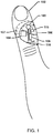
- FIG. 1 illustrates an embodiment electronic patch 106 including a pulse oximeter placed on a patient 102, such as on a skin surface of a finger of a patient 102.
- an electronic patch 106 may be flexible and resilient so that placement and removal of the electronic patch 106 from the patient 102 does not damage the electronic patch 106.
- the electronic patch 102 may include a pulse oximeter circuit comprised of a light output circuit 104 (e.g., a circuit including one or more LEDs that output light) and a light receiver circuit 107 (e.g., a circuit including one or more phototransistor) configured to measure light transmitted through the patient's skin and tissue emitted by the light output circuit 104, and a processor 108 connected to the light output circuit 104 and light receiver circuit 107 configured with processor executable instructions to control the operations of and/or receive measurements from the pulse oximeter (e.g., the light output circuit 104 and/or the light receiver circuit 107).
- a pulse oximeter circuit comprised of a light output circuit 104 (e.g., a circuit including one or more LEDs that output light) and a light receiver circuit 107 (e.g., a circuit including one or more phototransistor) configured to measure light transmitted through the patient's skin and tissue emitted by the light output circuit 104, and a processor 108 connected to the
- the processor 108 may be further configured with processor executable instructions to determine the patient's 102 blood oxygen level and/or pulse based on the measurements from the pulse oximeter (e.g., the light output circuit 104 and/or the light receiver circuit 107).
- the light output circuit 104, the light receiver circuit 107, and/or the processor 108 may be connected to a low power source 105, such as a coin cell battery.
- the electronic patch 106 may also include at least one accelerometer 115 connected to the processor 108 and the low power source 105.
- the processor 108 may receive acceleration measurements from the accelerometer 115 and may be configured with processor executable instructions to turn on and/or off the accelerometer 115 and to control the operations of the pulse oximeter (e.g., the light output circuit 104 and/or the light receiver circuit 107) based at least in part on the measurements received from the accelerometer 115.
- the accelerometer 115 may remain on once the patch is activated or powered up/on, and continually draw current from the low power source 105.
- the accelerometer 115 may draw an amount of current that is relatively smaller than the amount of current drawn by the pulse oximeter (e.g., the light output circuit 104 and/or the light receiver circuit 107). While the accelerometer 115 may continually operate, the processor 108 may intermittently turn on and off the pulse oximeter (e.g., the light output circuit 104 and/or the light receiver circuit 107) to reduce the total amount of current drawn from the low power source 105 compared with continually leaving the pulse oximeter (e.g., the light output circuit 104 and/or the light receiver circuit 107) on.
- the pulse oximeter e.g., the light output circuit 104 and/or the light receiver circuit 107
- the accelerometer 115 may draw 0.5 microamperes of current in a low power mode and the pulse oximeter (e.g., the light output circuit 104 and/or the light receiver circuit 107) may draw 20 milliamperes of current.
- the pulse oximeter e.g., the light output circuit 104 and/or the light receiver circuit 107
- the pulse oximeter e.g., the light output circuit 104 and/or the light receiver circuit 107
- only turning on the pulse oximeter e.g., the light output circuit 104 and/or the light receiver circuit 107) intermittently, such as only when a patient is in a rest state such that measurements would be accurate, may extend the life of the low power source 105, such as a coin cell battery, compared to the life of the low power source 105 that could be achieved with the pulse oximeter always on.
- Accelerometer data may be sampled acceleration measurements provided by the accelerometer 115 or interrupts received from the accelerometer 115 indicating a threshold meeting or exceeding acceleration event (e.g., a peak acceleration event) was detected by the accelerometer.
- the processor 108 may analyze the acceleration measurements and make determinations based on the received acceleration data.
- accelerometer data are interrupts signaled by the accelerometer 115, the processor 108 may analyze the interrupt that was signaled and make determinations based on the type of interrupt received.
- Receiving interrupts from the accelerometer 115 may be a lower power alternative to receiving and processing acceleration measurements by the processor 108.
- the electronic patch 106 may also include a transceiver 116 connected to an antenna and the processor 108 and the low power source 105.
- the processor 108 may establish wireless connections, e.g., Bluetooth ® connections, with remote devices, such as a smart phone, and may exchange data with the remote devices.
- the transceiver 116 is used merely as an example of one type of wireless connection device suitable for use in the various embodiments, in other configurations receivers and/or transmitters, separately or in conjunction may be substituted for transceiver 116 to provide transmission and/or reception capabilities to the processor 108 as needed for various different use cases for the electronic patch 106.
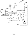
- FIG. 2 is a circuit diagram illustrating an embodiment circuit 200 for a pulse oximeter including an accelerometer 230.
- the circuit 200 may be integrated into an electronic patch worn by a patient, such as the electronic patch 106 described above.
- a low voltage power source may power the processor 218 or the processor may be powered by a separate power source (not shown).
- the low voltage source 202 powers the capacitor 206a when the switch 204a is closed.
- the switch may be located anywhere on the loop containing the low voltage source 202 and switch 204a, provided it can electrically separate the low voltage source 202 and switch 204a.
- the processor 218 may control when the switch 204a opens or closes. For example, the processor 218 may close switch 204a to allow capacitor 206a to collect electric charge.
- the charge on the capacitor 206a may correspond via a known relationship to the voltage across the capacitor 206a.
- the voltage across the capacitor 206a may be monitored by the voltmeter 220.
- the voltmeter 220 may report the measured
- the processor 218 may open switch 204a at an appropriate time to provide power to a light output circuit 203 to cause the light output circuit 203 to generate light.
- light output circuit 203 may include switches 204b and 204c and a red LED 210a and infrared LED 210b.
- the processor 218 may close switches 204b, 204c to allow charge to flow from capacitor 206a to red LED 210a and infrared LED 210b.
- the switches 204b and 204c may be closed consecutively to measure the different wavelength absorption rates in quick succession. Switches 204b, 204c may remain open while the capacitor is charging to prevent unnecessary drain on the low voltage source 202.
- Resistors 222a, 222b may be connected in series with a red LED 210a and an infrared LED 210b to control the current passing through each LED 210a, 210b.
- the resistors 222a, 222b may have the same or different resistances than each other.
- the resistors 222a, 222b may provide greater control on the allocation of current from the capacitor 206a, thus helping to eliminate the need for higher-current power supplies.
- the switches 204b, 204c may be closed by the processor 218 to provide charge from the capacitor 206a to the red LED 210a and infrared LED 210b for a period of time to cause the LEDs 210a and 210b to emit red light 212a and infrared light 212b, respectively.
- the switches 204b, 204c may be opened by the microprocessor 218 to isolate the LEDs 210a and 210b from the capacitor 206a to stop providing charge from the capacitor 206a to the LEDs 210a and 210b and stop the LEDs 210a and 210b from emitting red light 212a and infrared light 212b, respectively.
- light bursts may be generated from the red LED 210a and infrared LED 210b, and the current draw of the circuit 200 may be minimized by only turning the red LED 210a and infrared LED 210b on for the period of time.
- red LED 210a and infrared LED 210b When sufficient current passes through the red LED 210a and infrared LED 210b, they emit red light 212a and infrared light 212b, respectively.
- the light 212a, 212b propagates through a body part 244, such as a fingertip or earlobe.
- the amount of light absorbed by the body part 244 may be a function of the amount of oxygen in the blood and the amount of blood in the body part 244 at the time of sampling. Specifically, a body part 244 with a relatively large amount of oxygen may tend to absorb more infrared light 212b and less red light 212a. A body part 244 with a relatively small amount of oxygen may tend to absorb less infrared light 212b and more red light 212a.
- the red light 212a and infrared light 212b may be absorbed by a photodetector 214, such as a phototransistor or a light sensor, of a light receiver circuit 207 comprised of the photodetector 214, a switch 204d, a capacitor 206b, and an A/D converter 216.
- a photodetector 214 such as a phototransistor or a light sensor
- a light receiver circuit 207 comprised of the photodetector 214, a switch 204d, a capacitor 206b, and an A/D converter 216.
- Analysis of the absolute amplitude of the detected light signal as well as the relative amplitudes of the detected red light 212a and detected infrared light 212b may reveal various properties of the blood, such as the pulse profile and the amount of oxygen in the blood.
- the photodetector 214 may be powered by voltage source 224a.
- Processor 218 may control switch 204d. When the switch 204d is open, current may not flow from the photodetector 214 and data may not be collected. When the switch 204d is closed, the photodetector 214 may transfer data to the microprocessor 218.
- the microprocessor may synchronize the opening and closing of switch 204d with switches 204a, 204b, 204c such that switch 204d is only closed when the photodetector 214 intercepts the light 212a, 212b. Power demand may be further reduced by leaving the switch 204d open when the photodetector is not receiving useful data.
- the switch 204d When the switch 204d is closed, current may flow from the photodetector 214 to the capacitor 206b and be stored in the capacitor 206b at the input to the A/D converter 216.
- the A/D converter 216 may measure the voltage at the capacitor 206b and transfer the data to the microprocessor 218.
- the on periods of the red LED 210a and infrared LED 210b may be synchronized with the opening and closing of switch 204d by microprocessor 218.
- the microprocessor 218 may close the switch 204d to allow the photodetector 214 to start integrating its received signal just before the red LED 210a and infrared LED 210b are turned on by discharging the capacitor 206a, and may control the A/D converter 216 to take a voltage measurement as soon as the red LED 210a and infrared LED 210b are off.
- the photodetector 214 may be a single device and may comprise two separate detectors tuned separately for each wavelength of light in use.
- the digital output of the A/D converter 216 may be the output of the light receiver circuit 207 which may be analyzed by the processor 218 as measurements of the blood oxygen level.
- the processor 218 may also be connected to the accelerometer 230 and may receive acceleration measurements from the accelerometer 230 and may be configured with processor executable instructions to control the operations of the switches 204a, 204b, 204c, and/or 204d to turn the light output circuit 203 and/or the light receiver circuit 207 on and/or off, respectively, based at least in part on the measurements received from the accelerometer 230.
- the light output circuit 203 may be turned on and/or off and controlled to generate light
- the light receiver circuit 207 may be turned on and/or off and controlled to receive and measure light by the processor 218 based at least in part on the measurements received from the accelerometer 230.
- the processor 218 may be configured with processor executable instructions to determine active and/or rest states of a patient based at least in part on the measurements from the accelerometer 230 and may only operate the light output circuit 203 and/or light receiver circuit 207 during rest periods to increase the accuracy of the oxygen measurements and pulse measurements and reduce power consumption.
- the accelerometer 230 measurements may be used by the processor 218 to indicate the accuracy of the pulse oximeter readings, for example by indicating the reading was or was not taken during a period of high patient movement.
- the accelerometer 230 measurements may be used by the processor 218 to identify rest and/or sleep times and lower the measurement rate of the pulse oximeter during rest and/or sleep times to improve (e.g., reduce) low power source 202 consumption during rest and/or sleep times.
- the accelerometer 230 measurements may be used by the processor 218 to target blood oxygen measurements and pulse measurements to correspond to low and/or high (e.g., peak) activity. Enabling the ability to identify rest and/or high (e.g., peak) activity as well as measure blood oxygen levels and pulse in a single device (e.g., one electronic patch) may allow for significant diagnostic capabilities.
- a single patch design may be configured to operate in various combinations of embodiments described herein and therefore be customized for a particular need based on a per-patient diagnostic need related to the diagnostic purpose.
- increases in the heart rate or changes in blood oxygen levels measured by the pulse oximeter may be compared with accelerometer data by the processor 218 to determine whether the changes are related to activity or stress.
- a transceiver 232 may also be connected to an antenna 233 and the processor 218.
- the processor 218 may establish wireless connections, e.g., Bluetooth ® connections, with remote devices, such as a smart phone, and may exchange data with the remote devices.
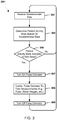
- FIG. 3 illustrates an embodiment method 300 for controlling a pulse oximeter based on a patient activity state indicated by accelerometer readings.
- the operations of method 300 may be performed by a processor of an electronic patch including a pulse oximeter and accelerometer, such as patch 106 described above.
- the processor may receive accelerometer data from an accelerometer connected to the processor. Accelerometer Data may be sampled acceleration measurements provided by the accelerometer or interrupts received from the accelerometer indicating a threshold meeting or exceeding acceleration event (e.g., a peak acceleration event) was detected by the accelerometer.
- acceleration event e.g., a peak acceleration event
- the processor may analyze the interrupt signaled and make determinations based on the type of interrupt received.
- the processor may determine a patient activity state based on the received accelerometer data. For example, the processor may determine whether the patient's activity state is at rest or active based on the received accelerometer data (e.g., when the accelerometer data are acceleration measurements by analyzing the acceleration measurements to determine whether the patient's activity state is at rest or active, when the accelerometer data are interrupts by analyzing the interrupts to determine whether interrupt signals a level of acceleration correlated with rest or active states, etc.).
- Rest and/or active states may be determined based on the received acceleration measurements (e.g., acceleration data and/or interrupt signals) by comparing the received acceleration measurements to threshold values associated with the rest and/or active states. For example, though some acceleration may be indicated for a patient (e.g., the patient may not be perfectly still), the level of acceleration may be below the threshold value for a rest state and the patient's activity state may still be determined to be a rest state.
- the received acceleration measurements e.g., acceleration data and/or interrupt signals
- the processor may turn on the pulse oximeter in block 307. In this manner, the pulse oximeter may remain powered off and only draw current from a power source, such as a coin cell battery, when the patient activity state is indicated as a rest state based on accelerometer data.
- the processor may control the pulse oximeter to take measurements, such as pulse rate measurements, blood oxygen measurements, etc. In this manner, the pulse oximeter may only be activated when the patient is in a rest state and the pulse oximeter measurements are more likely to be accurate, and thereby conserving power by limiting pulse oximeter activity.
- the processor may turn off the pulse oximeter and perform the operations of the method 300 in a loop by receiving further accelerometer data block 302. In this manner, once a pulse oximeter measurement is taken, the pulse oximeter may be turned off to conserve power.
- FIG. 4 illustrates an embodiment method 400 for indicating an accuracy of pulse oximeter readings based on accelerometer readings.
- the operations of method 400 may be performed by a processor of an electronic patch including a pulse oximeter and accelerometer, such as patch 106 described above.
- the processor may receive accelerometer data and in block 304 the processor may determine a patient activity state based on the received accelerometer data.
- the processor may control the pulse oximeter to take measurements, such as pulse rate measurements, blood oxygen measurements, etc.
- the processor may indicate the patient activity state with the pulse oximeter measurement.
- the determined patient activity state such as at rest or active, may be correlated with the pulse oximeter measurements in a memory, such as a measurement database.
- the processor may repeat the method 400 in a loop by returning to perform the operations in block 302.
- FIG. 5 illustrates an embodiment method 500 for changing a pulse oximeter measurement rate based on a patient activity state indicated by accelerometer readings.
- the operations of method 500 may be performed by a processor of an electronic patch including a pulse oximeter and accelerometer, such as patch 106 described above.
- the processor may control the pulse oximeter to take measurements, such as pulse rate measurements, blood oxygen measurements, etc., at a measurement rate.
- a measurement rate may be a variable value (e.g., a sampling rate, such as measurements per minute) indicated in a memory and the processor may activate the pulse oximeter periodically according to the measurement rate.
- the processor may receive accelerometer data and in block 304 the processor may determine a patient activity state based on the received accelerometer data.
- the default level may be a relatively higher measurement rate, such as a high sampling rate. In this manner, when the patient is not at rest, a higher relative sampling rate may be used to activate the pulse oximeter more often.
- the processor may return to performing the operations in block 502 to control the pulse oximeter at the default level measurement rate.
- the processor may set the measurement rate to a rest level in block 506.
- the rest level may be a relatively lower measurement rate, such as a low sampling rate. In this manner, when the patient is at rest, fewer samples may be taken by the pulse oximeter, conserving battery power.
- the processor may return to performing the operations in block 502 to control the pulse oximeter at the rest state level measurement rate.
- FIG. 6 illustrates an embodiment method 600 for aligning pulse oximeter readings with a patient activity state based on accelerometer readings.
- the operations of method 600 may be performed by a processor of an electronic patch including a pulse oximeter and accelerometer, such as the patch 106 described above.
- the processor may receive accelerometer data and in block 304 the processor may determine a patient activity state based on the received accelerometer data.
- the processor may determine whether a patient activity state meets a pulse oximeter measurement condition.
- patient activity states may be correlated with instructions to take a pulse oximeter measurement.
- a patient entering a rest state may be correlated with taking a pulse oximeter measurement
- a patient entering a high activity state may be correlated with taking a pulse oximeter measurement
- a patient reaching a maximum or peak activity rate may be correlated with taking a pulse oximeter measurement.
- the processor may perform the operations in block 302 as described above.
- the processor may control the pulse oximeter to take measurements in block 308 as described above.
- FIG. 7 illustrates an embodiment method 700 for correlating heart rate increases with patient states.
- the operations of method 700 may be performed by a processor of an electronic patch including a pulse oximeter and accelerometer, such as patch 106 described above.
- the processor may control the pulse oximeter to take measurements, such as pulse rate measurements, blood oxygen measurements, etc.
- the processor may receive accelerometer data in block 302 and determine a patient activity state based on the received accelerometer data in block 304.
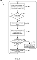
- FIG. 8 illustrates an embodiment method 800 for controlling a pulse oximeter based on a patient activity state indicated by accelerometer readings.
- the operations of the method 800 may be performed by a processor of an electronic patch including a pulse oximeter and accelerometer, such as the patch 106 described above.
- the processor may be powered on.
- the electronic patch may be removed from a wrapper and applied to a patient resulting in the processor of the electronic patch being powered on.
- the processor may reset and start a measurement period countdown timer.
- the measurement period countdown timer may be a countdown timer monitored by the processor that may be set to a minimum time to wait between performing pulse oximeter measurements.
- the minimum time to wait between performing pulse oximeter measurements may be set to any time value, such as less that 30 minutes, 30 minutes, more than 30 minutes, etc., and may vary based on patient medical conditions or any other factor.
- the processor may reset and start the measurement window countdown timer in block 808.
- the measurement window countdown timer may be a countdown timer monitored by the processor that may be set to a maximum time to wait for the patient to enter a rest state to perform a pulse oximeter measurement.
- the measurement window countdown timer may provide a maximum time to wait to attempt to take a more accurate pulse oximeter measurement during a patient rest state.
- the processor may default to taking a pulse oximeter measurement regardless of the current patient activity state.
- a total period of time equal to the measurement period countdown timer plus the measurement window countdown timer may not be exceeded without taking a pulse oximeter measurement reading, regardless of the patient activity state.
- the maximum time to wait to attempt to take a more accurate pulse oximeter measurement during a patient rest state may be set to any time value, such as less that 10 minutes, 10 minutes, more than 10 minutes, etc., and may vary based on patient medical conditions or any other factor.
- the processor will default to taking a pulse oximeter measurement regardless of the current patient activity state.
- the processor may perform operations of like numbered blocks of the method 300 described above with reference to FIG. 3 to receive accelerometer data and determine a patient activity state.
- the processor may determine whether the measurement window countdown timer has expired.
- the processor may determine whether the patient activity state indicates a rest state in determination block 306 as described above with reference to FIG. 3 .
- the processor may again receive accelerometer data in block 302 and determine a patient activity state in block 304.
- the processor may turn on the pulse oximeter in block 307, take measurements in block 308, and turn off the pulse oximeter in block 309 as described with reference to FIG. 3 .
- the pulse oximeter may be activated to take a measurement, thereby conserving battery life by only powering on the pulse oximeter to take a measurement when the measurement is likely to be accurate or is needed to not miss a measurement window.
- the processor may indicate the patient activity state with the pulse oximeter measurement as described with reference to FIG. 4 .
- the processor may perform the method 800 in a loop by resetting and starting the measurement period countdown timer in block 804. In this manner, the pulse oximeter may only be turned on periodically to take measurements and thereby conserve battery life.
- An embodiment patch may be configured to transmit data to any of a variety of computing devices.
- FIG. 9 illustrates a computing device 900 suitable for use in various embodiments.
- the computing device 900 may exchange data from the electronic patches discussed above, and may perform one or more of the operations of methods 300, 400, 500, 600, 700, and/or 800 described above.
- accelerometer and/or pulse oximeter measurements may be sent to the computing device 900 and pulse oximeter control signals may be sent to the electronic patch from the computing device 900.
- the computing device 900 may include a processor 901 coupled to a touch screen controller 804 and an internal memory 902.
- the processor 901 may be one or more multicore ICs designated for general or specific processing tasks.
- the internal memory 902 may be volatile or non-volatile memory, and may also be secure and/or encrypted memory, or unsecure and/or unencrypted memory, or any combination thereof.
- the touch screen controller 904 and the processor 901 may also be coupled to a touch screen panel 912, such as a resistive-sensing touch screen, capacitive-sensing touch screen, infrared sensing touch screen, etc.
- the computing device 900 may have one or more radio signal transceivers 908 (e.g., Peanut®, Bluetooth®, Zigbee®, Wi-Fi, RF, cellular, etc.) and antennae 910, for sending and receiving, coupled to each other and/or to the processor 901.
- the transceivers 908 and antennae 910 may be used with the above-mentioned circuitry to implement the various wireless transmission protocol stacks and interfaces.
- the computing device 900 may include a cellular network wireless modem chip 916 that enables communication via a cellular network, such as an eMBMS network, and is coupled to the processor.
- the computing device 900 may include a peripheral device connection interface 918 coupled to the processor 901.
- the peripheral device connection interface 918 may be singularly configured to accept one type of connection, or configured to accept various types of physical and communication connections, common or proprietary, such as USB, FireWire, Thunderbolt, or PCIe.
- the peripheral device connection interface 918 may also be coupled to a similarly configured peripheral device connection port (not shown).
- the computing device 900 may also include speakers 914 for providing audio outputs.
- the computing device 900 may also include a housing 920, constructed of a plastic, metal, or a combination of materials, for containing all or some of the components discussed herein.
- the computing device 900 may include a power source 922 coupled to the processor 901, such as a disposable or rechargeable battery.
- the rechargeable battery may also be coupled to the peripheral device connection port to receive a charging current from a source external to the computing device 900.
- Processors of computing devices suitable for use in various embodiments may be any programmable microprocessor, microcomputer or multiple processor chip or chips that can be configured by software instructions (applications) to perform a variety of functions, including the functions of the various embodiments described above.
- multiple processors may be provided, such as one processor dedicated to wireless communication functions and one processor dedicated to running other applications.
- software applications may be stored in internal memory before they are accessed and loaded into the processors.
- the processors may include internal memory sufficient to store the application software instructions.
- the internal memory may be a volatile or nonvolatile memory, such as flash memory, or a mixture of both.
- a general reference to memory refers to memory accessible by the processors including internal memory or removable memory plugged into the various devices and memory within the processors.
- DSP digital signal processor
- ASIC application specific integrated circuit
- FPGA field programmable gate array
- a general-purpose processor may be a microprocessor, but, in the alternative, the processor may be any conventional processor, controller, microcontroller, or state machine.
- a processor may also be implemented as a combination of computing devices, e.g., a combination of a DSP and a microprocessor, a plurality of microprocessors, one or more microprocessors in conjunction with a DSP core, or any other such configuration. Alternatively, some steps or methods may be performed by circuitry that is specific to a given function.
- the functions in the various embodiments may be implemented in hardware, software, firmware, or any combination thereof. If implemented in software, the functions may be stored as one or more processor executable instructions or code on a non-transitory computer readable medium or non-transitory processor readable medium.
- the steps of a method or algorithm disclosed herein may be embodied in a processor-executable software module that may reside on a non-transitory computer-readable or processor-readable storage medium.
- Non-transitory computer-readable or processor-readable storage media may be any storage media that may be accessed by a computer or a processor.
- non-transitory computer-readable or processor-readable media may include RAM, ROM, EEPROM, FLASH memory, CD-ROM or other optical disk storage, magnetic disk storage or other magnetic storage devices, or any other medium that may be used to store desired program code in the form of instructions or data structures and that may be accessed by a computer.
- Disk and disc includes compact disc (CD), laser disc, optical disc, digital versatile disc (DVD), floppy disk, and blu-ray disc where disks usually reproduce data magnetically, while discs reproduce data optically with lasers. Combinations of the above are also included within the scope of non-transitory computer-readable and processor-readable media.
- the operations of a method or algorithm may reside as one or any combination or set of codes and/or instructions on a non-transitory processor-readable medium and/or computer-readable medium, which may be incorporated into a computer program product.
Landscapes
- Health & Medical Sciences (AREA)
- Life Sciences & Earth Sciences (AREA)
- Physics & Mathematics (AREA)
- Engineering & Computer Science (AREA)
- General Health & Medical Sciences (AREA)
- Pathology (AREA)
- Biomedical Technology (AREA)
- Heart & Thoracic Surgery (AREA)
- Medical Informatics (AREA)
- Molecular Biology (AREA)
- Surgery (AREA)
- Animal Behavior & Ethology (AREA)
- Biophysics (AREA)
- Public Health (AREA)
- Veterinary Medicine (AREA)
- Signal Processing (AREA)
- Physiology (AREA)
- Artificial Intelligence (AREA)
- Computer Vision & Pattern Recognition (AREA)
- Psychiatry (AREA)
- Spectroscopy & Molecular Physics (AREA)
- Optics & Photonics (AREA)
- Dentistry (AREA)
- Oral & Maxillofacial Surgery (AREA)
- Measurement Of The Respiration, Hearing Ability, Form, And Blood Characteristics Of Living Organisms (AREA)
Applications Claiming Priority (3)
| Application Number | Priority Date | Filing Date | Title |
|---|---|---|---|
| US201462053483P | 2014-09-22 | 2014-09-22 | |
| US14/800,833 US10258267B2 (en) | 2014-09-22 | 2015-07-16 | Pulse oximeter with an accelerometer |
| PCT/US2015/040832 WO2016048436A1 (en) | 2014-09-22 | 2015-07-17 | Pulse oximeter with an accelerometer |
Publications (2)
| Publication Number | Publication Date |
|---|---|
| EP3197358A1 EP3197358A1 (en) | 2017-08-02 |
| EP3197358B1 true EP3197358B1 (en) | 2019-05-08 |
Family
ID=55524635
Family Applications (1)
| Application Number | Title | Priority Date | Filing Date |
|---|---|---|---|
| EP15747302.6A Active EP3197358B1 (en) | 2014-09-22 | 2015-07-17 | Pulse oximeter with an accelerometer |
Country Status (6)
| Country | Link |
|---|---|
| US (1) | US10258267B2 (ja) |
| EP (1) | EP3197358B1 (ja) |
| JP (1) | JP6530060B2 (ja) |
| KR (1) | KR20170061671A (ja) |
| CN (1) | CN106687038B (ja) |
| WO (1) | WO2016048436A1 (ja) |
Families Citing this family (38)
| Publication number | Priority date | Publication date | Assignee | Title |
|---|---|---|---|---|
| US10226187B2 (en) | 2015-08-31 | 2019-03-12 | Masimo Corporation | Patient-worn wireless physiological sensor |
| JP7497956B2 (ja) | 2016-05-13 | 2024-06-11 | スミス アンド ネフュー ピーエルシー | センサが使用可能な創傷監視および治療装置 |
| JP6801370B2 (ja) * | 2016-10-28 | 2020-12-16 | 富士通株式会社 | センサ装置 |
| US11690570B2 (en) | 2017-03-09 | 2023-07-04 | Smith & Nephew Plc | Wound dressing, patch member and method of sensing one or more wound parameters |
| WO2018162732A1 (en) | 2017-03-09 | 2018-09-13 | Smith & Nephew Plc | Apparatus and method for imaging blood in a target region of tissue |
| US10524735B2 (en) * | 2017-03-28 | 2020-01-07 | Apple Inc. | Detecting conditions using heart rate sensors |
| CN110650713B (zh) | 2017-04-11 | 2022-06-24 | 史密夫及内修公开有限公司 | 用于传感器实现的伤口敷料的部件定位和应力释放 |
| CA3062991A1 (en) | 2017-05-15 | 2018-11-22 | Smith & Nephew Plc | Negative pressure wound therapy system using eulerian video magnification |
| AU2018269112B2 (en) | 2017-05-15 | 2024-05-02 | Smith & Nephew Plc | Wound analysis device and method |
| EP3641627B1 (en) | 2017-06-23 | 2023-05-31 | Smith & Nephew PLC | Positioning of sensors for sensor enabled wound monitoring or therapy |
| US20190000394A1 (en) * | 2017-07-03 | 2019-01-03 | Mediatek Inc. | Physiological monitoring devices and physiological monitoring method |
| GB201809007D0 (en) | 2018-06-01 | 2018-07-18 | Smith & Nephew | Restriction of sensor-monitored region for sensor-enabled wound dressings |
| GB201804502D0 (en) | 2018-03-21 | 2018-05-02 | Smith & Nephew | Biocompatible encapsulation and component stress relief for sensor enabled negative pressure wound therapy dressings |
| US11925735B2 (en) | 2017-08-10 | 2024-03-12 | Smith & Nephew Plc | Positioning of sensors for sensor enabled wound monitoring or therapy |
| GB201718870D0 (en) | 2017-11-15 | 2017-12-27 | Smith & Nephew Inc | Sensor enabled wound therapy dressings and systems |
| US11759144B2 (en) | 2017-09-10 | 2023-09-19 | Smith & Nephew Plc | Systems and methods for inspection of encapsulation and components in sensor equipped wound dressings |
| GB201804971D0 (en) | 2018-03-28 | 2018-05-09 | Smith & Nephew | Electrostatic discharge protection for sensors in wound therapy |
| GB201718859D0 (en) | 2017-11-15 | 2017-12-27 | Smith & Nephew | Sensor positioning for sensor enabled wound therapy dressings and systems |
| US11596553B2 (en) | 2017-09-27 | 2023-03-07 | Smith & Nephew Plc | Ph sensing for sensor enabled negative pressure wound monitoring and therapy apparatuses |
| WO2019072531A1 (en) | 2017-09-28 | 2019-04-18 | Smith & Nephew Plc | NEUROSTIMULATION AND MONITORING USING A SENSOR ACTIVATED WOUND SURVEILLANCE AND TREATMENT APPARATUS |
| JP2021502845A (ja) | 2017-11-15 | 2021-02-04 | スミス アンド ネフュー ピーエルシーSmith & Nephew Public Limited Company | 統合センサ対応型創傷モニタリングおよび/または治療被覆材ならびにシステム |
| WO2020053290A1 (en) | 2018-09-12 | 2020-03-19 | Smith & Nephew Plc | Device, apparatus and method of determining skin perfusion pressure |
| GB201820927D0 (en) | 2018-12-21 | 2019-02-06 | Smith & Nephew | Wound therapy systems and methods with supercapacitors |
| EP3941401A1 (en) | 2019-03-18 | 2022-01-26 | Smith & Nephew plc | Design rules for sensor integrated substrates |
| MX2021012686A (es) | 2019-04-17 | 2022-01-06 | Masimo Corp | Sistemas, dispositivos y metodos para monitoreo del paciente. |
| US11234620B2 (en) | 2019-06-24 | 2022-02-01 | Medtronic, Inc. | Performing measurements using sensors of a medical device system |
| JP7343313B2 (ja) | 2019-06-26 | 2023-09-12 | フクダ電子株式会社 | 生体情報測定装置 |
| JP7323352B2 (ja) * | 2019-06-26 | 2023-08-08 | フクダ電子株式会社 | 生体情報測定装置 |
| USD919100S1 (en) | 2019-08-16 | 2021-05-11 | Masimo Corporation | Holder for a patient monitor |
| USD919094S1 (en) | 2019-08-16 | 2021-05-11 | Masimo Corporation | Blood pressure device |
| USD917704S1 (en) | 2019-08-16 | 2021-04-27 | Masimo Corporation | Patient monitor |
| USD985498S1 (en) | 2019-08-16 | 2023-05-09 | Masimo Corporation | Connector |
| GB201914443D0 (en) | 2019-10-07 | 2019-11-20 | Smith & Nephew | Sensor enabled negative pressure wound monitoring apparatus with different impedances inks |
| USD927699S1 (en) | 2019-10-18 | 2021-08-10 | Masimo Corporation | Electrode pad |
| USD933232S1 (en) | 2020-05-11 | 2021-10-12 | Masimo Corporation | Blood pressure monitor |
| WO2022243427A1 (en) * | 2021-05-21 | 2022-11-24 | Imp Scandinavia Aps | Smart patch |
| US20230051939A1 (en) * | 2021-08-11 | 2023-02-16 | Mediatek Inc. | Physiological monitoring apparatus and physiological monitoring method |
| WO2024018312A1 (en) * | 2022-07-22 | 2024-01-25 | Medtronic, Inc. | Accelerometer-triggered sensor measurement on exertion |
Family Cites Families (21)
| Publication number | Priority date | Publication date | Assignee | Title |
|---|---|---|---|---|
| JPH0315502U (ja) | 1989-06-28 | 1991-02-15 | ||
| JPH04188299A (ja) * | 1990-11-22 | 1992-07-06 | Iwatsu Electric Co Ltd | 異常状態検出器 |
| US5746697A (en) | 1996-02-09 | 1998-05-05 | Nellcor Puritan Bennett Incorporated | Medical diagnostic apparatus with sleep mode |
| US6697658B2 (en) | 2001-07-02 | 2004-02-24 | Masimo Corporation | Low power pulse oximeter |
| US6763256B2 (en) * | 2002-08-16 | 2004-07-13 | Optical Sensors, Inc. | Pulse oximeter |
| US7238159B2 (en) * | 2004-04-07 | 2007-07-03 | Triage Wireless, Inc. | Device, system and method for monitoring vital signs |
| JP2007105316A (ja) * | 2005-10-14 | 2007-04-26 | Konica Minolta Sensing Inc | 生体情報測定器 |
| US7558622B2 (en) | 2006-05-24 | 2009-07-07 | Bao Tran | Mesh network stroke monitoring appliance |
| DE102006036920B3 (de) * | 2006-08-04 | 2007-11-29 | Nirlus Engineering Ag | Verfahren zur Messung der Glukosekonzentration in pulsierendem Blut |
| US9560994B2 (en) * | 2008-03-26 | 2017-02-07 | Covidien Lp | Pulse oximeter with adaptive power conservation |
| US8437824B2 (en) * | 2009-06-17 | 2013-05-07 | Sotera Wireless, Inc. | Body-worn pulse oximeter |
| WO2011010244A1 (en) | 2009-07-20 | 2011-01-27 | Koninklijke Philips Electronics N.V. | Method for operating a monitoring system |
| EP2896356A1 (en) * | 2009-12-23 | 2015-07-22 | DELTA, Dansk Elektronik, Lys & Akustik | A monitoring system |
| EP2603132B1 (en) | 2010-08-09 | 2016-04-20 | MIR SRL Medical International Research | Portable device for monitoring and reporting of medical information for the evidence -based management of patients with chronic respiratory disease |
| US8571622B2 (en) * | 2010-08-31 | 2013-10-29 | General Electric Company | Method for reducing power consumption in pulse oximeter systems, pulse oximeter system and pulse oximeter sensor |
| US20120229800A1 (en) * | 2011-03-08 | 2012-09-13 | Fluke Corporation | Pulse oximeter test instruments and methods |
| WO2013155503A1 (en) | 2012-04-13 | 2013-10-17 | Langer Alois A | Outpatient health emergency warning system |
| US8838236B2 (en) | 2012-09-21 | 2014-09-16 | Physio-Control. Inc. | Wearable cardiac defibrillator system with anti-bradyarrhythmia pacing and methods |
| WO2014066059A1 (en) | 2012-10-22 | 2014-05-01 | The Regents Of The University Of California | Networked sensor systems for remote patient monitoring |
| US9107644B2 (en) * | 2013-07-05 | 2015-08-18 | James Tyler Frix | Continuous transdermal monitoring system and method |
| JP6247619B2 (ja) * | 2014-09-22 | 2017-12-13 | 株式会社東芝 | 生体情報測定装置 |
-
2015
- 2015-07-16 US US14/800,833 patent/US10258267B2/en active Active
- 2015-07-17 CN CN201580050694.2A patent/CN106687038B/zh active Active
- 2015-07-17 JP JP2017513218A patent/JP6530060B2/ja active Active
- 2015-07-17 EP EP15747302.6A patent/EP3197358B1/en active Active
- 2015-07-17 KR KR1020177007667A patent/KR20170061671A/ko unknown
- 2015-07-17 WO PCT/US2015/040832 patent/WO2016048436A1/en active Application Filing
Non-Patent Citations (1)
| Title |
|---|
| None * |
Also Published As
| Publication number | Publication date |
|---|---|
| KR20170061671A (ko) | 2017-06-05 |
| WO2016048436A1 (en) | 2016-03-31 |
| US10258267B2 (en) | 2019-04-16 |
| JP2017533737A (ja) | 2017-11-16 |
| JP6530060B2 (ja) | 2019-06-12 |
| EP3197358A1 (en) | 2017-08-02 |
| US20160081601A1 (en) | 2016-03-24 |
| CN106687038B (zh) | 2020-02-21 |
| CN106687038A (zh) | 2017-05-17 |
Similar Documents
| Publication | Publication Date | Title |
|---|---|---|
| EP3197358B1 (en) | Pulse oximeter with an accelerometer | |
| AU2021200167B2 (en) | Detecting conditions using heart rate sensors | |
| CN204542088U (zh) | 老人用智能健康腕带 | |
| EP3432771B1 (en) | Tracking contact quality of vital signs measurement sensors | |
| CN105979858B (zh) | 心率监测设备 | |
| US11786137B2 (en) | Physiological sampling during predetermined activities | |
| CN107106023B (zh) | 允许能够确定血属性的设备的低电流操作的电路 | |
| US11747877B2 (en) | Two-phase deployment-initiated wakeup mechanism for body-mountable electronic device | |
| WO2014099290A1 (en) | Short-range low-power wireless communication enabled analyte meter | |
| US20150342477A1 (en) | Dynamic operation of optical heart rate sensors | |
| EP3148424A1 (en) | Optical pressure sensor | |
| US11510624B2 (en) | Wireless vital sign monitoring | |
| KR20070060628A (ko) | 사용자의 휴대폰 소유 여부에 따라 슬롯 모드를 제어하는장치 및 그 방법 |
Legal Events
| Date | Code | Title | Description |
|---|---|---|---|
| STAA | Information on the status of an ep patent application or granted ep patent |
Free format text: STATUS: THE INTERNATIONAL PUBLICATION HAS BEEN MADE |
|
| PUAI | Public reference made under article 153(3) epc to a published international application that has entered the european phase |
Free format text: ORIGINAL CODE: 0009012 |
|
| STAA | Information on the status of an ep patent application or granted ep patent |
Free format text: STATUS: REQUEST FOR EXAMINATION WAS MADE |
|
| 17P | Request for examination filed |
Effective date: 20170216 |
|
| AK | Designated contracting states |
Kind code of ref document: A1 Designated state(s): AL AT BE BG CH CY CZ DE DK EE ES FI FR GB GR HR HU IE IS IT LI LT LU LV MC MK MT NL NO PL PT RO RS SE SI SK SM TR |
|
| AX | Request for extension of the european patent |
Extension state: BA ME |
|
| DAV | Request for validation of the european patent (deleted) | ||
| DAX | Request for extension of the european patent (deleted) | ||
| GRAP | Despatch of communication of intention to grant a patent |
Free format text: ORIGINAL CODE: EPIDOSNIGR1 |
|
| STAA | Information on the status of an ep patent application or granted ep patent |
Free format text: STATUS: GRANT OF PATENT IS INTENDED |
|
| INTG | Intention to grant announced |
Effective date: 20180802 |
|
| GRAJ | Information related to disapproval of communication of intention to grant by the applicant or resumption of examination proceedings by the epo deleted |
Free format text: ORIGINAL CODE: EPIDOSDIGR1 |
|
| STAA | Information on the status of an ep patent application or granted ep patent |
Free format text: STATUS: REQUEST FOR EXAMINATION WAS MADE |
|
| GRAP | Despatch of communication of intention to grant a patent |
Free format text: ORIGINAL CODE: EPIDOSNIGR1 |
|
| STAA | Information on the status of an ep patent application or granted ep patent |
Free format text: STATUS: GRANT OF PATENT IS INTENDED |
|
| INTC | Intention to grant announced (deleted) | ||
| INTG | Intention to grant announced |
Effective date: 20181120 |
|
| GRAS | Grant fee paid |
Free format text: ORIGINAL CODE: EPIDOSNIGR3 |
|
| GRAA | (expected) grant |
Free format text: ORIGINAL CODE: 0009210 |
|
| STAA | Information on the status of an ep patent application or granted ep patent |
Free format text: STATUS: THE PATENT HAS BEEN GRANTED |
|
| AK | Designated contracting states |
Kind code of ref document: B1 Designated state(s): AL AT BE BG CH CY CZ DE DK EE ES FI FR GB GR HR HU IE IS IT LI LT LU LV MC MK MT NL NO PL PT RO RS SE SI SK SM TR |
|
| REG | Reference to a national code |
Ref country code: GB Ref legal event code: FG4D |
|
| REG | Reference to a national code |
Ref country code: CH Ref legal event code: EP Ref country code: AT Ref legal event code: REF Ref document number: 1128920 Country of ref document: AT Kind code of ref document: T Effective date: 20190515 |
|
| REG | Reference to a national code |
Ref country code: DE Ref legal event code: R096 Ref document number: 602015029869 Country of ref document: DE Ref country code: IE Ref legal event code: FG4D |
|
| REG | Reference to a national code |
Ref country code: NL Ref legal event code: MP Effective date: 20190508 |
|
| REG | Reference to a national code |
Ref country code: LT Ref legal event code: MG4D |
|
| PG25 | Lapsed in a contracting state [announced via postgrant information from national office to epo] |
Ref country code: LT Free format text: LAPSE BECAUSE OF FAILURE TO SUBMIT A TRANSLATION OF THE DESCRIPTION OR TO PAY THE FEE WITHIN THE PRESCRIBED TIME-LIMIT Effective date: 20190508 Ref country code: HR Free format text: LAPSE BECAUSE OF FAILURE TO SUBMIT A TRANSLATION OF THE DESCRIPTION OR TO PAY THE FEE WITHIN THE PRESCRIBED TIME-LIMIT Effective date: 20190508 Ref country code: NO Free format text: LAPSE BECAUSE OF FAILURE TO SUBMIT A TRANSLATION OF THE DESCRIPTION OR TO PAY THE FEE WITHIN THE PRESCRIBED TIME-LIMIT Effective date: 20190808 Ref country code: SE Free format text: LAPSE BECAUSE OF FAILURE TO SUBMIT A TRANSLATION OF THE DESCRIPTION OR TO PAY THE FEE WITHIN THE PRESCRIBED TIME-LIMIT Effective date: 20190508 Ref country code: PT Free format text: LAPSE BECAUSE OF FAILURE TO SUBMIT A TRANSLATION OF THE DESCRIPTION OR TO PAY THE FEE WITHIN THE PRESCRIBED TIME-LIMIT Effective date: 20190908 Ref country code: AL Free format text: LAPSE BECAUSE OF FAILURE TO SUBMIT A TRANSLATION OF THE DESCRIPTION OR TO PAY THE FEE WITHIN THE PRESCRIBED TIME-LIMIT Effective date: 20190508 Ref country code: FI Free format text: LAPSE BECAUSE OF FAILURE TO SUBMIT A TRANSLATION OF THE DESCRIPTION OR TO PAY THE FEE WITHIN THE PRESCRIBED TIME-LIMIT Effective date: 20190508 Ref country code: NL Free format text: LAPSE BECAUSE OF FAILURE TO SUBMIT A TRANSLATION OF THE DESCRIPTION OR TO PAY THE FEE WITHIN THE PRESCRIBED TIME-LIMIT Effective date: 20190508 Ref country code: ES Free format text: LAPSE BECAUSE OF FAILURE TO SUBMIT A TRANSLATION OF THE DESCRIPTION OR TO PAY THE FEE WITHIN THE PRESCRIBED TIME-LIMIT Effective date: 20190508 |
|
| PG25 | Lapsed in a contracting state [announced via postgrant information from national office to epo] |
Ref country code: BG Free format text: LAPSE BECAUSE OF FAILURE TO SUBMIT A TRANSLATION OF THE DESCRIPTION OR TO PAY THE FEE WITHIN THE PRESCRIBED TIME-LIMIT Effective date: 20190808 Ref country code: LV Free format text: LAPSE BECAUSE OF FAILURE TO SUBMIT A TRANSLATION OF THE DESCRIPTION OR TO PAY THE FEE WITHIN THE PRESCRIBED TIME-LIMIT Effective date: 20190508 Ref country code: RS Free format text: LAPSE BECAUSE OF FAILURE TO SUBMIT A TRANSLATION OF THE DESCRIPTION OR TO PAY THE FEE WITHIN THE PRESCRIBED TIME-LIMIT Effective date: 20190508 Ref country code: GR Free format text: LAPSE BECAUSE OF FAILURE TO SUBMIT A TRANSLATION OF THE DESCRIPTION OR TO PAY THE FEE WITHIN THE PRESCRIBED TIME-LIMIT Effective date: 20190809 |
|
| REG | Reference to a national code |
Ref country code: AT Ref legal event code: MK05 Ref document number: 1128920 Country of ref document: AT Kind code of ref document: T Effective date: 20190508 |
|
| PG25 | Lapsed in a contracting state [announced via postgrant information from national office to epo] |
Ref country code: SK Free format text: LAPSE BECAUSE OF FAILURE TO SUBMIT A TRANSLATION OF THE DESCRIPTION OR TO PAY THE FEE WITHIN THE PRESCRIBED TIME-LIMIT Effective date: 20190508 Ref country code: RO Free format text: LAPSE BECAUSE OF FAILURE TO SUBMIT A TRANSLATION OF THE DESCRIPTION OR TO PAY THE FEE WITHIN THE PRESCRIBED TIME-LIMIT Effective date: 20190508 Ref country code: AT Free format text: LAPSE BECAUSE OF FAILURE TO SUBMIT A TRANSLATION OF THE DESCRIPTION OR TO PAY THE FEE WITHIN THE PRESCRIBED TIME-LIMIT Effective date: 20190508 Ref country code: DK Free format text: LAPSE BECAUSE OF FAILURE TO SUBMIT A TRANSLATION OF THE DESCRIPTION OR TO PAY THE FEE WITHIN THE PRESCRIBED TIME-LIMIT Effective date: 20190508 Ref country code: EE Free format text: LAPSE BECAUSE OF FAILURE TO SUBMIT A TRANSLATION OF THE DESCRIPTION OR TO PAY THE FEE WITHIN THE PRESCRIBED TIME-LIMIT Effective date: 20190508 Ref country code: CZ Free format text: LAPSE BECAUSE OF FAILURE TO SUBMIT A TRANSLATION OF THE DESCRIPTION OR TO PAY THE FEE WITHIN THE PRESCRIBED TIME-LIMIT Effective date: 20190508 |
|
| REG | Reference to a national code |
Ref country code: DE Ref legal event code: R097 Ref document number: 602015029869 Country of ref document: DE |
|
| PG25 | Lapsed in a contracting state [announced via postgrant information from national office to epo] |
Ref country code: SM Free format text: LAPSE BECAUSE OF FAILURE TO SUBMIT A TRANSLATION OF THE DESCRIPTION OR TO PAY THE FEE WITHIN THE PRESCRIBED TIME-LIMIT Effective date: 20190508 Ref country code: IT Free format text: LAPSE BECAUSE OF FAILURE TO SUBMIT A TRANSLATION OF THE DESCRIPTION OR TO PAY THE FEE WITHIN THE PRESCRIBED TIME-LIMIT Effective date: 20190508 Ref country code: MC Free format text: LAPSE BECAUSE OF FAILURE TO SUBMIT A TRANSLATION OF THE DESCRIPTION OR TO PAY THE FEE WITHIN THE PRESCRIBED TIME-LIMIT Effective date: 20190508 |
|
| REG | Reference to a national code |
Ref country code: CH Ref legal event code: PL |
|
| PLBE | No opposition filed within time limit |
Free format text: ORIGINAL CODE: 0009261 |
|
| STAA | Information on the status of an ep patent application or granted ep patent |
Free format text: STATUS: NO OPPOSITION FILED WITHIN TIME LIMIT |
|
| PG25 | Lapsed in a contracting state [announced via postgrant information from national office to epo] |
Ref country code: TR Free format text: LAPSE BECAUSE OF FAILURE TO SUBMIT A TRANSLATION OF THE DESCRIPTION OR TO PAY THE FEE WITHIN THE PRESCRIBED TIME-LIMIT Effective date: 20190508 |
|
| 26N | No opposition filed |
Effective date: 20200211 |
|
| REG | Reference to a national code |
Ref country code: BE Ref legal event code: MM Effective date: 20190731 |
|
| PG25 | Lapsed in a contracting state [announced via postgrant information from national office to epo] |
Ref country code: PL Free format text: LAPSE BECAUSE OF FAILURE TO SUBMIT A TRANSLATION OF THE DESCRIPTION OR TO PAY THE FEE WITHIN THE PRESCRIBED TIME-LIMIT Effective date: 20190508 |
|
| PG25 | Lapsed in a contracting state [announced via postgrant information from national office to epo] |
Ref country code: CH Free format text: LAPSE BECAUSE OF NON-PAYMENT OF DUE FEES Effective date: 20190731 Ref country code: BE Free format text: LAPSE BECAUSE OF NON-PAYMENT OF DUE FEES Effective date: 20190731 Ref country code: LI Free format text: LAPSE BECAUSE OF NON-PAYMENT OF DUE FEES Effective date: 20190731 Ref country code: SI Free format text: LAPSE BECAUSE OF FAILURE TO SUBMIT A TRANSLATION OF THE DESCRIPTION OR TO PAY THE FEE WITHIN THE PRESCRIBED TIME-LIMIT Effective date: 20190508 Ref country code: LU Free format text: LAPSE BECAUSE OF NON-PAYMENT OF DUE FEES Effective date: 20190717 |
|
| PG25 | Lapsed in a contracting state [announced via postgrant information from national office to epo] |
Ref country code: IE Free format text: LAPSE BECAUSE OF NON-PAYMENT OF DUE FEES Effective date: 20190717 |
|
| PG25 | Lapsed in a contracting state [announced via postgrant information from national office to epo] |
Ref country code: CY Free format text: LAPSE BECAUSE OF FAILURE TO SUBMIT A TRANSLATION OF THE DESCRIPTION OR TO PAY THE FEE WITHIN THE PRESCRIBED TIME-LIMIT Effective date: 20190508 |
|
| PG25 | Lapsed in a contracting state [announced via postgrant information from national office to epo] |
Ref country code: IS Free format text: LAPSE BECAUSE OF FAILURE TO SUBMIT A TRANSLATION OF THE DESCRIPTION OR TO PAY THE FEE WITHIN THE PRESCRIBED TIME-LIMIT Effective date: 20190908 |
|
| PG25 | Lapsed in a contracting state [announced via postgrant information from national office to epo] |
Ref country code: MT Free format text: LAPSE BECAUSE OF FAILURE TO SUBMIT A TRANSLATION OF THE DESCRIPTION OR TO PAY THE FEE WITHIN THE PRESCRIBED TIME-LIMIT Effective date: 20190508 Ref country code: HU Free format text: LAPSE BECAUSE OF FAILURE TO SUBMIT A TRANSLATION OF THE DESCRIPTION OR TO PAY THE FEE WITHIN THE PRESCRIBED TIME-LIMIT; INVALID AB INITIO Effective date: 20150717 |
|
| PG25 | Lapsed in a contracting state [announced via postgrant information from national office to epo] |
Ref country code: MK Free format text: LAPSE BECAUSE OF FAILURE TO SUBMIT A TRANSLATION OF THE DESCRIPTION OR TO PAY THE FEE WITHIN THE PRESCRIBED TIME-LIMIT Effective date: 20190508 |
|
| REG | Reference to a national code |
Ref country code: GB Ref legal event code: 732E Free format text: REGISTERED BETWEEN 20230413 AND 20230419 |
|
| REG | Reference to a national code |
Ref country code: GB Ref legal event code: 732E Free format text: REGISTERED BETWEEN 20230420 AND 20230426 |
|
| PGFP | Annual fee paid to national office [announced via postgrant information from national office to epo] |
Ref country code: GB Payment date: 20230725 Year of fee payment: 9 |
|
| PGFP | Annual fee paid to national office [announced via postgrant information from national office to epo] |
Ref country code: FR Payment date: 20230725 Year of fee payment: 9 Ref country code: DE Payment date: 20230726 Year of fee payment: 9 |