EP3197088B1 - Method and apparatus for transmitting control information in wireless communication system - Google Patents
Method and apparatus for transmitting control information in wireless communication system Download PDFInfo
- Publication number
- EP3197088B1 EP3197088B1 EP17160679.1A EP17160679A EP3197088B1 EP 3197088 B1 EP3197088 B1 EP 3197088B1 EP 17160679 A EP17160679 A EP 17160679A EP 3197088 B1 EP3197088 B1 EP 3197088B1
- Authority
- EP
- European Patent Office
- Prior art keywords
- pdcch
- downlink
- subframe
- subframe configuration
- user equipment
- Prior art date
- Legal status (The legal status is an assumption and is not a legal conclusion. Google has not performed a legal analysis and makes no representation as to the accuracy of the status listed.)
- Active
Links
- 238000000034 method Methods 0.000 title claims description 58
- 238000004891 communication Methods 0.000 title claims description 19
- 238000001514 detection method Methods 0.000 claims description 37
- 239000013256 coordination polymer Substances 0.000 claims description 27
- 125000004122 cyclic group Chemical group 0.000 claims description 12
- 230000011664 signaling Effects 0.000 claims description 10
- 230000005540 biological transmission Effects 0.000 description 72
- 230000008569 process Effects 0.000 description 19
- 230000002776 aggregation Effects 0.000 description 16
- 238000004220 aggregation Methods 0.000 description 16
- 238000010586 diagram Methods 0.000 description 16
- 238000012544 monitoring process Methods 0.000 description 14
- 238000013468 resource allocation Methods 0.000 description 14
- 230000004044 response Effects 0.000 description 8
- 238000012545 processing Methods 0.000 description 5
- 230000008054 signal transmission Effects 0.000 description 5
- 230000000694 effects Effects 0.000 description 4
- 101100243399 Caenorhabditis elegans pept-2 gene Proteins 0.000 description 3
- 101000741965 Homo sapiens Inactive tyrosine-protein kinase PRAG1 Proteins 0.000 description 3
- 102100038659 Inactive tyrosine-protein kinase PRAG1 Human genes 0.000 description 3
- 238000005516 engineering process Methods 0.000 description 3
- 230000006870 function Effects 0.000 description 3
- 239000011159 matrix material Substances 0.000 description 3
- 101100189913 Caenorhabditis elegans pept-1 gene Proteins 0.000 description 2
- 101100243401 Caenorhabditis elegans pept-3 gene Proteins 0.000 description 2
- 101100203596 Caenorhabditis elegans sol-1 gene Proteins 0.000 description 2
- 239000000969 carrier Substances 0.000 description 2
- 238000013507 mapping Methods 0.000 description 2
- 238000010295 mobile communication Methods 0.000 description 2
- 238000012986 modification Methods 0.000 description 2
- 230000004048 modification Effects 0.000 description 2
- 241000760358 Enodes Species 0.000 description 1
- 235000008694 Humulus lupulus Nutrition 0.000 description 1
- 230000004913 activation Effects 0.000 description 1
- 230000004931 aggregating effect Effects 0.000 description 1
- 238000003491 array Methods 0.000 description 1
- 230000000903 blocking effect Effects 0.000 description 1
- 238000012790 confirmation Methods 0.000 description 1
- 230000001419 dependent effect Effects 0.000 description 1
- 238000007429 general method Methods 0.000 description 1
- 230000007774 longterm Effects 0.000 description 1
- 230000010363 phase shift Effects 0.000 description 1
- 238000003672 processing method Methods 0.000 description 1
- 230000001360 synchronised effect Effects 0.000 description 1
- 230000009466 transformation Effects 0.000 description 1
Images


Classifications
-
- H—ELECTRICITY
- H04—ELECTRIC COMMUNICATION TECHNIQUE
- H04L—TRANSMISSION OF DIGITAL INFORMATION, e.g. TELEGRAPHIC COMMUNICATION
- H04L27/00—Modulated-carrier systems
- H04L27/26—Systems using multi-frequency codes
- H04L27/2601—Multicarrier modulation systems
- H04L27/2602—Signal structure
-
- H—ELECTRICITY
- H04—ELECTRIC COMMUNICATION TECHNIQUE
- H04L—TRANSMISSION OF DIGITAL INFORMATION, e.g. TELEGRAPHIC COMMUNICATION
- H04L27/00—Modulated-carrier systems
- H04L27/26—Systems using multi-frequency codes
- H04L27/2601—Multicarrier modulation systems
- H04L27/2602—Signal structure
- H04L27/2605—Symbol extensions, e.g. Zero Tail, Unique Word [UW]
- H04L27/2607—Cyclic extensions
-
- H—ELECTRICITY
- H04—ELECTRIC COMMUNICATION TECHNIQUE
- H04L—TRANSMISSION OF DIGITAL INFORMATION, e.g. TELEGRAPHIC COMMUNICATION
- H04L5/00—Arrangements affording multiple use of the transmission path
- H04L5/003—Arrangements for allocating sub-channels of the transmission path
- H04L5/0053—Allocation of signaling, i.e. of overhead other than pilot signals
-
- H—ELECTRICITY
- H04—ELECTRIC COMMUNICATION TECHNIQUE
- H04L—TRANSMISSION OF DIGITAL INFORMATION, e.g. TELEGRAPHIC COMMUNICATION
- H04L5/00—Arrangements affording multiple use of the transmission path
- H04L5/0091—Signaling for the administration of the divided path
- H04L5/0094—Indication of how sub-channels of the path are allocated
-
- H—ELECTRICITY
- H04—ELECTRIC COMMUNICATION TECHNIQUE
- H04L—TRANSMISSION OF DIGITAL INFORMATION, e.g. TELEGRAPHIC COMMUNICATION
- H04L5/00—Arrangements affording multiple use of the transmission path
- H04L5/22—Arrangements affording multiple use of the transmission path using time-division multiplexing
-
- H—ELECTRICITY
- H04—ELECTRIC COMMUNICATION TECHNIQUE
- H04L—TRANSMISSION OF DIGITAL INFORMATION, e.g. TELEGRAPHIC COMMUNICATION
- H04L27/00—Modulated-carrier systems
- H04L27/26—Systems using multi-frequency codes
- H04L27/2601—Multicarrier modulation systems
- H04L27/2602—Signal structure
- H04L27/2603—Signal structure ensuring backward compatibility with legacy system
Definitions
- the present invention relates to a wireless communication system, and more particularly, to a method of transmitting/receiving control information in a TDD (Time Division Duplex)-based wireless communication system and apparatus therefor.
- TDD Time Division Duplex
- a wireless communication system is developing to diversely cover a wide range to provide such a communication service as an audio communication service, a data communication service and the like.
- the wireless communication is a sort of a multiple access system capable of supporting communications with multiple users by sharing available system resources (e.g., bandwidth, transmit power, etc.).
- the multiple access system may include one of CDMA (code division multiple access) system, FDMA (frequency division multiple access) system, TDMA (time division multiple access) system, OFDMA (orthogonal frequency division multiple access) system, SC-FDMA (single carrier frequency division multiple access) system and the like.
- CDMA code division multiple access
- FDMA frequency division multiple access
- TDMA time division multiple access
- OFDMA orthogonal frequency division multiple access
- SC-FDMA single carrier frequency division multiple access
- One object of the present invention is to provide a method and apparatus for efficiently transmitting/receiving control information in a wireless communication system. Another object of the present invention is to provide a channel format, resource allocation, a signal processing, and an apparatus therefor to efficiently transmit/receive the control information. Still another object of the present invention is to provide a method and apparatus for efficiently allocating resource to transmit/receive the control information.
- control information can be efficiently transmitted and received in a wireless communication system.
- the present invention may be able to provide a channel format for efficiently transmitting/receiving the control information, resource allocation, a signal processing method.
- the present invention may be able to efficiently allocate resource for transmitting/receiving the control information.
- CDMA code division multiple access
- FDMA frequency division multiple access
- TDMA time division multiple access
- OFDMA orthogonal frequency division multiple access
- SC-FDMA single carrier frequency division multiple access
- CDMA can be implemented with such a radio technology as UTRA (universal terrestrial radio access), CDMA 2000 and the like.
- TDMA can be implemented with such a radio technology as GSM/GPRS/EDGE (Global System for Mobile communications)/General Packet Radio Service/Enhanced Data Rates for GSM Evolution).
- OFDMA can be implemented with such a radio technology as IEEE 802.11 (Wi-Fi), IEEE 802.16 (WiMAX), IEEE 802.20, E-UTRA (Evolved UTRA), etc.
- UTRA is a part of UMTS (Universal Mobile Telecommunications System).
- 3GPP (3rd Generation Partnership Project) LTE (long term evolution) is a part of E-UMTS (Evolved UMTS) that uses E-UTRA
- LTE-A LTE-Advanced
- 3GPP LTE-A LTE-Advanced
- a user equipment receives information from a base station via a downlink (DL) and transmits information to the base station via an uplink (UL) in a wireless communication system.
- the information transceived by the base station and the user equipment includes data and various control information and there may exist various physical channels according to a kind and usage of the information transceived by the user equipment and the base station.
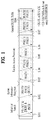
- FIG. 1 illustrates a diagram for explaining a general method of transmitting physical channels used for 3GPP LTE system and signals via the same.
- the user equipment may perform an initial cell search for synchronizing with a base station and the like [S101].
- the user equipment may receive a primary synchronization channel (P-SCH) and a secondary synchronization channel (S-SCH) from the base station, may synchronize with the base station, and then may obtain information such as a cell ID and the like.
- the user equipment may receive a physical broadcast channel (PBCH) from the base station and then may be able to obtain broadcast information within the cell.
- PBCH physical broadcast channel
- the user equipment may receive a downlink reference signal (DL RS) and may be then able to check a downlink channel state.
- PBCH physical broadcast channel
- DL RS downlink reference signal
- the user equipment may receive a physical downlink control channel (PDCCH) and a physical downlink shared channel (PDSCH) according to the physical downlink control channel (PDCCH) and may be then able to obtain detailed system information [S102].
- PDCH physical downlink control channel
- PDSCH physical downlink shared channel
- the user equipment may be able to perform a random access procedure to complete the access to the base station [S103 to S106].
- the user equipment may transmit a preamble via a physical random access channel (PRACH) [S103] and may be then able to receive a response message via PDCCH and a corresponding PDSCH in response to the preamble [S104].
- PRACH physical random access channel
- it may be able to perform a contention resolution procedure such as a transmission [S105] of an additional physical random access channel and a channel reception [S106] of a physical downlink control channel and a corresponding physical downlink shared channel.
- the user equipment may be able to perform a PDCCH/PDSCH reception [S107] and a Physical Uplink Shared Channel/Physical Uplink Control Channel (PUSCH/PUCCH) transmission [S108] as a general uplink/downlink signal transmission procedure.
- Control information transmitted to a base station by a user equipment may be commonly named uplink control information (hereinafter abbreviated UCI).
- the UCI may include Hybrid Automatic Repeat and reQuest Acknowledgement/Negative-ACK (HARQ-ACK/NACK), Scheduling Request (SR), Channel State Information (CSI), and the like.
- HARQ-ACK/NACK Hybrid Automatic Repeat and reQuest Acknowledgement/Negative-ACK
- SR Scheduling Request
- CSI Channel State Information
- the CSI may include Channel Quality Indication (CQI), Precoding Matrix Indication (PMI), Rank Indication (RI) information and the like.
- CQI Channel Quality Indication
- PMI Precoding Matrix Indication
- RI Rank Indication
- the UCI is normally transmitted via PUCCH by periods. Yet, in case that both control information and traffic data need to be simultaneously transmitted, the UCI may be transmitted on PUSCH. Moreover, the UCI may be non-periodically transmitted in response to a request/indication made by a network.
- FIG. 2 illustrates an example of a radio frame structure.
- UL/DL (uplink/downlink) data packet transmission is performed by a unit of subframe.
- one subframe is defined as a predetermined time interval including a plurality of OFDM symbols.
- a type-1 radio frame structure applicable to FDD (Frequency Division Duplex) and a type-2 radio frame structure applicable to TDD (Time Division Duplex) are supported.
- FIG. 2 (a) is a diagram for a structure of a downlink radio frame of type 1.
- a DL (downlink) radio frame includes 10 subframes. Each of the subframes includes 2 slots. And, a time taken to transmit one subframe is defined as a transmission time interval (hereinafter abbreviated TTI). For instance, one subframe may have a length of 1 ms and one slot may have a length of 0.5 ms.
- One slot may include a plurality of OFDM symbols in the time domain and may include a plurality of resource blocks (RBs) in the frequency domain. Since 3GPP LTE system uses OFDM in downlink, OFDM symbol represents one symbol period. The OFDM symbol may be named SC-FDMA symbol or symbol period.
- Resource block (RB) is a resource allocation unit and may include a plurality of contiguous subcarriers in one slot.
- the number of OFDM symbols included in one slot may vary in accordance with a configuration of cyclic prefix (CP).
- the CP may be categorized into an extended CP and a normal CP. For instance, in case that OFDM symbols are configured by the normal CP, the number of OFDM symbols included in one slot may be 7. In case that OFDM symbols are configured by the extended CP, since the length of one OFDM symbol increases, the number of OFDM symbols included in one slot may be smaller than that of the case of the normal CP. In case of the extended CP, for instance, the number of OFDM symbols included in one slot may be 6. If a channel status is unstable (e.g., a UE is moving at high speed), it may be able to use the extended CP to further reduce the inter-symbol interference.
- one subframe includes 14 OFDM symbols.
- first maximum 3 OFDM symbols of each subframe may be allocated to PDCCH (physical downlink control channel), while the rest of the OFDM symbols are allocated to PDSCH (physical downlink shared channel).
- FIG. 2 (b) is a diagram for a structure of a downlink radio frame of type 2.
- a type-2 radio frame includes 2 half frames. Each of the half frame includes 4 (5) normal subframes and 1 (0) special subframe. The normal subframe may be used for UL or DL according to an uplink-downlink configuration. Each of subframes includes 2 slots.
- Table 1 is an example of a subframe configuration in a radio frame according to the UL-DL configuration.
- Uplink-downlink configuration Downlink-to-Uplink Switch-point periodicity Subframe number 0 1 2 3 4 5 6 7 8 9 0 5 ms D S U U U D S U U U 1 5 ms D S U U D D S U U D 2 5 ms D S U D D D S U D D 3 10 ms D S U U U D D D D D D 4 10 ms D S U U D D D D D D 5 10 ms D S U D D D D D D D D 6 5 ms D S U U U U D S U U U D S U U D
- D indicates a DL subframe
- U indicates an UL subframe
- S indicates a special subframe, respectively.
- the special subframe includes DwPTS (downlink pilot time slot), GP (guard period) and UpPTS (uplink pilot time slot).
- the DwPTS is used for initial cell search, synchronization or channel estimation in a user equipment.
- the UpPTS is used for channel estimation in a base station and uplink transmission synchronization of a user equipment.
- the guard period is a period for eliminating interference between uplink and downlink, which is generated in uplink due to multi-path delay of a downlink signal.
- the above-described structures of the radio frame are exemplary only. And, the number of subframes included in a radio frame, the number of slots included in the subframe and the number of symbols included in the slot may be modified in various ways.
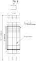
- FIG. 3 illustrates an exemplary resource grid for a downlink slot.
- one downlink (DL) slot may include a plurality of OFDM symbols in the time domain.
- one DL slot exemplarily includes 7 OFDM symbols and one resource block (RB) exemplarily includes 12 subcarriers in the frequency domain, but the present invention is not limited thereto.
- Each element on a resource grid is referred to as a resource element (hereinafter abbreviated RE).
- One resource block includes 12 ⁇ 7 resource elements.
- the number N DL of resource blocks included in a DL slot may depend on a DL transmission bandwidth.
- the structure of an uplink (UL) slot may be identical to that of the DL slot.
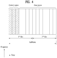
- FIG. 4 illustrates an exemplary structure of a downlink subframe.
- maximum 3 (4) OFDM symbols situated in a head part of a first slot of one subframe correspond to a control region to which control channels are allocated.
- the rest of OFDM symbols correspond to a data region to which PDSCH (physical downlink shared channel) is allocated and a basic resource unit of the data region is an RB.
- Examples of DL control channels used by LTE may include PCFICH (Physical Control Format Indicator Channel), PDCCH (Physical Downlink Control Channel), PHICH (Physical hybrid automatic repeat request indicator Channel) and the like.
- the PCFICH is transmitted in a first OFDM symbol of a subframe and carries information on the number of OFDM symbols used for a transmission of a control channel within the subframe.
- the PHICH is a response to UL transmission and carries a HARQ ACK/NACK (hybrid automatic repeat request acknowledgement/non-acknowledgement) signal.
- Control information carried on PDCCH may be referred to as downlink control information (hereinafter abbreviated DCI).
- the DCI may include UL scheduling information, DL scheduling information or a UL transmit power control command for a UE (user equipment) group.
- DCI downlink control information
- DCI formats of formats 0, 3, 3A, and 4 are defined for uplink and DCI formats of formats 1, 1A, 1B, 1C, 1D, 2, 2A, 2B, 2C and the like are defined for downlink.
- DCI format a kind of information field, the number of information field, the number of bits of each information field and the like may vary.
- DCI format may be able to selectively include a hopping flag, an RB assignment, an MCS (modulation coding scheme), an RV (redundancy version), an NDI (new data indicator), a TPC (transmit power control), a HARQ process number, a PMI (precoding matrix indicator) confirmation and the like according to a usage.
- a size of control information matched with DCI format may be different according to DCI format.
- a DCI format can be used for transmitting two or more kinds of control information. For instance, DCI format 0/1A is used for carrying DCI format 0 or DCI format 1, and DCI format 0 and DCI format 1 are distinguished by a flag field.
- PDCCH is able to carry a transmission format for DL-SCH (downlink shared channel) and resource allocation, resource allocation information for UL-SCH (uplink shared channel), paging information for PCH (paging channel), system information on DL-SCH, resource allocation information of an upper layer control message such as a random access response transmitted on PDSCH, a transmit power control command for individual user equipments within a random user equipment (UE) group, activation of VoIP (voice over IP) and the like.
- a plurality of PDCCHs may be transmitted in a control region and a user equipment may monitor a plurality of PDCCHs.
- PDCCH is configured with the aggregation of at least one or more contiguous CCEs (control channel elements).
- CCE is a logical assignment unit used to provide PDCCH with a code rate in accordance with a state of a radio channel.
- CCE corresponds to a plurality of REGs (resource element groups).
- a format of PDCCH and the number of bits of an available PDCCH are determined depending on correlation between the number of CCEs and a code rate provided by the CCEs.
- a base station determines PDCCH format in accordance with DCI to be transmitted to a user equipment and attaches CRC (cyclic redundancy check) to the control information.
- CRC is masked with a unique identifier (called RNTI (radio network temporary identifier)) in accordance with an owner or usage of PDCCH.
- RNTI radio network temporary identifier
- CRC may be masked with a unique identifier of the user equipment, i.e., C-RNTI (i.e., Cell-RNTI).
- C-RNTI i.e., Cell-RNTI
- CRC may be masked with a paging indication identifier (e.g., P-RNTI (Paging-RNTI)).
- P-RNTI Paging-RNTI
- SIB system information block
- CRC may be masked with a system information identifier (e.g., SI-RNTI (system information-RNTI).
- SI-RNTI system information-RNTI
- RA-RNTI random access-RNTI
- PDCCH carries a message that is known as DCI (downlink control information) and DCI may include resource allocation information and other control information for one user equipment or UE group.
- DCI downlink control information
- a plurality of PDCCHs may be transmitted within a subframe.
- Each PDCCH is transmitted using at least one CCE (control channel element) and each CCE corresponds to 9 sets of resource elements, each set comprising 4 resource elements.
- the 4 resource elements are referred to as an REG (Resource Element Group).
- 4 QPSK (quadrature phase shift keying) symbols are mapped to each REG.
- Resource elements occupied by RS reference signal
- the total number of REGs in a OFDM symbol may vary depending on whether a cell-specific reference signal exists.
- REG mapping by a unit of group comprising 4 resource elements
- other DL control channels e.g., PCFICH, PHICH, etc.
- REG is used for a basic resource unit of a control region.
- 4 PDCCH formats are supported as shown in Table 2. [Table 2] PDCCH format Number of CCEs (n) Number of REGs Number of PDCCH bits 0 1 9 72 1 2 18 144 2 4 36 288 3 8 72 576
- PDCCH has a format comprising n CCEs and may start in a CCE having a number corresponding to multiple of n.
- the number of CCEs used for a transmission of a specific PDCCH is determined by a base station in accordance with a channel state. For instance, a single CCE may be sufficient for a PDCCH provided for a user equipment having a good DL channel state (e.g., a case that the user equipment is located in the vicinity of a base station).
- a power level of PDCCH may be adjusted according to channel condition.
- a method introduced to LTE is to define a limited set of CCE positions where PDCCH is able to be positioned for each user equipment.
- the limited set of CCE positions for which a user equipment is able to search its own PDCCH may be referred to as a search space (SS).
- the search space may have a different size in accordance with each PDCCH format.
- a UE-specific and common search space are separately defined.
- the UE-specific search space may be individually configured for each user equipment and the range of the common search space is known to all user equipments.
- the UE-specific and common search space may be overlapped for a given user equipment.
- a base station may be unable to find CCE resources enough to transmit PDCCH to all available user equipments in a given sub frame.
- a UE-specific hopping sequence may apply to a start point of the UE-specific search space.
- Table 3 shows sizes of a common search space and a UE-specific search space.
- PDCCH format Number of CCEs (n) Number of PDCCH candidates in Common Number of PDCCH candidates in UE-specific 0 1 - 6 1 2 - 6 2 4 4 2 3 8 2 2
- a user equipment In order to keep a computation load according to due to the total count of blind decoding (BD) attempts under control, a user equipment is not required to perform searches for all the defined DCI formats at the same time.
- the user equipment always searches a UE-search space for DCI format 0 and DCI format 1A.
- the DCI format 0 and the DCI format 1A are equal to each other in size and may be identified by a flag included in a message.
- the user equipment may be required to receive an additional format, e.g., format 1, 1B, or 2 according to the PDSCH transmission mode configured by a base station.
- the user equipment may be able to search a common search space for DCI format 1A and DCI format 1C.
- the user equipment may be configured to search for DCI format 3 or DCI format 3A.
- the DCI format 3/3A may have the same size as that of the DCI format 0/1A, and they may be distinguished from each other by scrambling CRC with different (common) identifiers other than a UE-specific identifier.
- PDSCH transmission scheme according to a transmission mode and information contents of DCI formats are described in following.
- a user equipment may be required to perform maximum 44 times of blind decoding in a single subframe. Since checking an identical message with different CRC values requires only a trivial additional computational complexity, checking the identical message with different CRC values is not included in count of blind decoding.
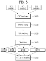
- FIG. 5 illustrates a flowchart for constructing PDCCH in a base station.
- a base station generates control information according to a DCI format.
- the base station may be able to select one DCI format among a plurality of DCI formats (DCI format 1, 2, ... , N) according to control information to be transmitted to a user equipment.
- a CRC cyclic redundancy check
- the CRC is masked with an identifier (e.g., RNTI (radio network temporary identifier)) in accordance with an owner or usage of PDCCH.
- RNTI radio network temporary identifier
- PDCCH is CRC scrambled with the identifier (e.g., RNTI).
- Table 4 shows an example of identifiers masked to PDCCH.
- Type Identifier Description UE-specific C-RNTI, temporary C-RNTI, semi-persistent C-RNTI Used for unique identification of user equipment Common P-RNTI Used for paging message SI-RNTI Used for system information RA-RNTI Used for random access response
- PDCCH carries control information for corresponding specific user equipment. In case that of the other RNTIs are used, PDCCH carries common control information which all user equipments within a cell receive.
- a base station creates a coded data (codeword) by performing a channel coding on the CRC attached control information [S420]. The base station performs a rate matching in accordance with a CCE aggregation level assigned to a PDCCH format [S430] and generates modulated symbols by modulating the coded data [S440].
- the modulated symbols constructing one PDCCH may have a CCE aggregation level set to one of 1, 2, 4 and 8. Thereafter, the base station maps the modulated symbols to physical resource elements (REs), i.e., CCE to RE mapping [S450].
- REs physical resource elements
- FIG. 6 illustrates a flowchart for processing PDCCH in a user equipment.
- a user equipment de-maps a physical resource element to CCE, i.e., RE to CCE demapping [S510]. Since the user equipment does not know which CCE aggregation level should be used to receive PDCCH, the user equipment performs demodulation with respect to each of the CCE aggregation levels [S520]. The user equipment performs a rate dematching for the demodulated data. Since the user equipment does not know which DCI format (or DCI payload size) is used for the control information, the user equipment performs a rate de-matching in accordance with each DCI format (or DCI payload size) [S530].
- the user equipment performs a channel decoding on the rate de-matched data according to a code rate, checks a CRC, and then detects whether there is an error [S540]. If an error does not occur, it indicates that the user equipment has found out PDCCH for its own. If an error occurs, the user equipment continuously performs a blind decoding for a different CCE aggregation level or a different DCI format (or DCI payload size). The user equipment, which has found out PDCCH of its own, eliminates the CRC from the decoded data and then obtains the control information.
- a plurality of PDCCHs for a plurality of user equipments may be transmitted within a control region of an identical subframe.
- a base station does not provide the user equipment with information about location of a corresponding PDCCH within the control region.
- the user equipment searches the subframe for PDCCH for its own in a manner of monitoring a set of PDCCH candidates.
- the term 'monitoring' means that a user equipment attempts to decode each of PDCCH candidates in accordance with each of PDCCH formats. This is referred to as a blind decoding (blind detection).
- blind decoding blind detection
- the user equipment simultaneously performs identification of PDCCH transmitted to the user equipment and decoding of the control information transmitted on a corresponding PDCCH. For instance, when PDCCH is de-masked with C-RNTI, if an error does not occur, it indicates that the user equipment has found out PDCCH of its own.
- the number of DCI formats is defined less than a kind of the control information transmitted on a PDCCH.
- a DCI format includes a plurality of information fields different from each other. According to a DCI format, a kind of the information field, the number of the information field, a bit number of each of the information fields and the like may vary. In addition, a size of the control information, which is matched with the DCI format, may vary according to the DCI format. Any DCI format can be used for transmitting two or more kinds of control information.
- FIG. 7 illustrates an exemplary structure of an uplink subframe used in LTE system.
- an uplink subframe includes a plurality of slots (e.g., 2 slots).
- a slot may include a different number of SC-FDMA symbols according to the length of CP.
- a slot may include 7 SC_FDMA symbols.
- a UL subframe may be divided into a control region and a data region in the frequency domain.
- the data region includes PUSCH and is used for transmitting a data signal such as voice and the like.
- the control region includes PUCCH and is used for transmitting control information.
- the control information includes HARQ-ACK/NACK, CQI (Channel Quality Information), PMI (Precoding Matrix Indicator), RI (Rank Indication), and the like.
- FIG. 8 illustrates an exemplary communication system for carrier aggregation (CA).
- CA carrier aggregation
- a wider UL/DL bandwidth can be supported by aggregating a plurality of UL/DL component carriers (CCs).
- Each of the component carriers may be adjacent to each other or non-adjacent to each other.
- the bandwidth of each component carrier may be determined independently.
- An asymmetric carrier aggregation is also possible, which means that the number of downlink component carrier (DL CC) and the number of uplink component carrier (UL CC) are different from each other.
- control information may be configured to be communicated on a specific CC only.
- the specific CC may be referred to as a primary CC and the other CCs may be referred to as a secondary CC.
- PDCCH for DL assignment may be transmitted on a DL CC # 0 and corresponding PDSCH may be transmitted on a DL CC # 2.
- the term 'component carrier' may be replaced by another equivalent term (e.g., a carrier, a cell, and the like).
- CIF carrier indicator field
- RRC Radio Resource Control
- a base station may assign a monitoring DL CC (set) so that BD complexity is reduced on a user equipment side.
- a user equipment may perform detection/decoding of PDCCH on a corresponding DL CC only.
- the base station may transmit PDCCH via a monitoring DL CC only.
- a monitoring DL CC set may be configured UE-specifically, UE group-specifically or cell-specifically.
- FIG. 9 illustrates an exemplary case that 3 DL CCs are aggregated and DL CC A is configured as a monitoring DL CC. If CIF is disabled, each of DL CCs may be able to transmit a PDCCH, which schedules a PDSCH of each of the DL CCs, without a CIF according to an LTE PDCCH rule. On the other hand, if CIF is enabled by upper layer signaling, only DL CC A may be able to transmit a PDCCH, which schedules a PDSCH of a different DL CC as well as a PDSCH of DL CC A using a CIF.
- PDCCH is not transmitted on DL CC B and DL CC C, which are not configured as a monitoring DL CC.
- the term 'monitoring DL CC' may be replaced by another equivalent term such as a monitoring carrier, a monitoring cell, a scheduling carrier, a scheduling cell, a serving carrier, a serving cell, and the like.
- a DL CC carrying PDSCH corresponding to PDCCH or a UL CC carrying PUSCH corresponding to PDCCH may be referred to as a scheduled carrier, a scheduled cell or the like.
- an FDD DL and TDD DL subframes use first n OFDM symbols of a subframe to transmit PDCCH, PHICH, PCFICH or the like, which is a physical channel used for transmitting various control informations and use the rest of OFDM symbols to transmit PDSCH.
- the number of symbols used for transmitting a control channel in each subframe is delivered to a user equipment dynamically via such a physical channel as PCFICH and the like or semi-statically via RRC signaling.
- the n value may be set from 1 symbol to maximum 4 symbols according to subframe characteristics and system characteristics (FDD/TDD, system bandwidth, etc.).
- E-PDCCH enhanced PDCCH
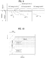
- FIG. 10 illustrates an example of assigning a downlink physical channel to a data region of a subframe.
- L-PDCCH region means a region to which legacy PDCCH is able to be assigned.
- a L-PDCCH region may mean a control region, a control channel resource region (i.e., CCE resource) where PDCCH is practically assigned, or a PDCCH search space.
- PDCCH may be additionally assigned to a data region (e.g., a resource region for PDSCH, refer to FIG. 4 ).
- the PDCCH assigned to a data region is referred to as an E-PDCCH.
- E-PDCCH The PDCCH assigned to a data region is referred to as an E-PDCCH.
- the E-PDCCH may exist by a subframe unit (i.e., through two slots).
- E-PDCCH may additionally obtain control channels resources by means of E-PDCCH, scheduling limitations due to the limited control channel resources of L-PDCCH region can be alleviated.
- a method of allocating and managing a resource for a DL control channel by using a data region (e.g., PDSCH) in a subframe is described with reference to drawings.
- a data region e.g., PDSCH
- the present invention may be identically/similarly applied to the relationship between a base station and a relay or the relationship between a relay and a user equipment as well.
- the relationship between a base station and a UE may be replaced by the relationship between a base station and a relay or the relationship between a relay and a UE in the following description.
- a relay and a UE may be generalized as a receiving end.
- E-PDCCH may be replaced by R-PDCCH (relay-PDCCH).
- E-PDCCH carries DCI.
- DCI refer to the description with reference to Table 2.
- E-PDCCH may be able to carry DL/UL scheduling information.
- the process for E-PDCCH/PDSCH or E-PDCCH/PUSCH is identical/similar to the description with reference to S107 and S108 of FIG. 1 . That is, a user equipment receives an E-PDCCH and may be then able to receive data/control information via a PDSCH corresponding to the E-PDCCH. And, the user equipment receives an E-PDCCH and may be then able to transmit data/control information via a PUSCH corresponding to the E-PDCCH.
- Processes for E-PDCCH transmission may be performed using the processes defined for the conventional LTE (refer to FIGS. 5 and 6 ) within a varying scope and may be modified as necessary.
- the conventional LTE system employs that a PDCCH candidate region (hereinafter, PDCCH search space) is reserved in advance within a control region and a PDCCH for a specific user equipment is transmitted via a part of the reserved region.
- PDCCH search space a PDCCH candidate region
- a PDCCH for a specific user equipment is transmitted via a part of the reserved region.
- a user equipment may be able to obtain PDCCH of its own in a PDCCH search space via a blind decoding.
- E-PDCCH may be transmitted through a part or a whole of pre-reserved resources.
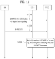
- FIG. 11 illustrates an exemplary process for resource allocation and receiving of E-PDCCH.
- a base station transmits E-PDCCH resource allocation (RA) information to a user equipment [S1210].
- the E-PDCCH RA information may include RB (or VRB (virtual resource block)) assignment information.
- the RB assignment information may be provided by a RB unit or a RBG (resource block group) unit.
- a RBG includes 2 or more contiguous RBs.
- the E-PDCCH RA information may be transmitted using an upper layer (e.g., RRC) signaling.
- the E-PDCCH RA information is used to pre-reserve an E-PDCCH resource (region).
- the base station transmits an E-PDCCH to the user equipment [S1220].
- the E-PDCCH may be transmitted within a part or a whole of E-PDCCH resources (e.g., M number of RBs) reserved in the step S1210.
- the user equipment monitors a resource (region) (hereinafter an E-PDCCH search space, simply a search space) via which the E-PDCCH may be transmitted [S1230].
- the E-PDCCH search space may be given as a part of the RB set assigned in the step S1210. In this case, monitoring may include blind decoding a plurality of E-PDCCH candidates in the search space.
- Example transmission of control information in consideration of a special subframe
- a timing gap is necessary when a DL subframe converts to a UL subframe.
- a special subframe is included between a DL SF and a UL SF.
- a special SF may have various configurations according to situations such as radio conditions, the position of a UE, and the like.
- Table 5 shows an example of a special SF.
- DwPTS/GP/UpPTS may be variously configured according to combinations of special SF configuration (simply, S configuration) and CP.
- Special subframe configuration Normal cyclic prefix in downlink Extended cyclic prefix in downlink DwPTS UpPTS DwPTS UpPTS Normal cyclic prefix in uplink Extended cyclic prefix in uplink Normal cyclic prefix in uplink Extended cyclic prefix in uplink 0 6592 ⁇ T s (3 symbols) 2192 ⁇ T s 2560 ⁇ T s 7680 ⁇ T s (3 symbols) 2192 ⁇ T s 2560 ⁇ T s 1 19760 ⁇ T s (9 symbols) 20480 ⁇ T s (8 symbols) 2 21952 ⁇ T s (10 symbols) 23040 ⁇ T s (9 symbols) 3 24144 ⁇ T s (11 symbols) 25600 ⁇ T s (10 symbols) 4 26336 ⁇ T s (12 symbols) 7680 ⁇ T s (3 symbols)
- a number in bracket indicates the length of a DwPTS period represented by the number of OFDM symbols.
- a DL SF, a UL SF, and a special SF are denoted by D, U, and S, respectively.
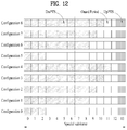
- FIG. 12 shows the number of OFDM symbols in DwPTS, GP, and UpPTS according to configurations of Table 5.
- FIG. 12 shows an exemplary case that normal CP is used (that is, 14 OFDM symbols per subframe).
- the number of OFDM symbols available for a DL transmission i.e., DwPTS
- S configuration #0 and #5 first 3 OFDM symbols of the first slot may be used for DwPTS.
- S configuration #1, #2, #3, #4, #6, #7, #8 all OFDM symbols of the first slot may be used for DwPTS.
- a PDSCH region does not exist or partly exists in a S SF.
- E-PDCCH is employed in a TDD system, it may not be possible to use E-PDCCH in a S SF according to an S configuration or may be inevitable to use E-PDCCH having a structure different from that of a general D.
- a general D may indicate a subframe configured as D according to the UL-DL configuration (e.g., Table 1).
- D means a general D if there is no specific mention.
- the present invention proposes a method of configuring a PDCCH search space (SS) in a S SF and a method of transmitting/receiving PDCCH, in case that E-PDCCH is configured to use in a TDD system.
- SS PDCCH search space
- an L-PDCCH region may mean a control region, a control channel resource region (e.g., CCE resource) to which a PDCCH can be assigned within the control region, or a PDCCH search space according to the context.
- an E-PDCCH region may mean a data region (refer to FIG. 4 ), a control channel resource region to which PDCCH can be assigned within the data region (i.e., a VRB resource allocated by an upper layer; refer to FIG. 11 ), or an E-PDCCH search space.
- legacy PDCCH and E-PDCCH may be collectively referred to as PDCCH unless they are treated differently.
- the present invention is explained based on a CCE aggregation level for coding PDCCH, the number of PDCCH candidates for which blind decoding should be performed, a DCI format for DL/UL scheduling, and the like as defined in the conventional LTE/LTE-A system, it is apparent that the present invention may be expanded/applied to a aggregation level, the number of PDCCH candidates, a DCI format and the like, which will be added or modified to a future standard in a similar manner.
- a method of transmitting/detecting PDCCH in a S SF and a method of configuring a SS for the same are described as follows.
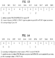
- FIG. 13 illustrates an example of performing transmission/reception of PDCCH according to Sol 1. It is assumed that UL-DL configuration #1 is configured in the present example.
- a PDCCH for a S SF special subframe
- S-PDCCH special subframe
- the user equipment may receive a PDSCH signal in a corresponding S SF or may transmit a PUSCH signal in a U corresponding to the S SF (2).
- ⁇ Sol 2 Transmission/detection for all PDCCHs (DCI formats) is performed only via an L-PDCCH region in S SF. That is, E-PDCCH transmission/reception/detection is not performed in S SF.
- FIG. 14 illustrates an example of performing PDCCH transmission/reception according to Sol 2.
- a PDCCH transmission/detection process in a general D may be performed for L-PDCCH and/or E-PDCCH according to a subframe configuration.
- a PDCCH detection process may be performed on the assumption that E-PDCCH is not transmitted in S SF irrespective of S configuration (2). That is, a PDCCH detection process can be performed for L-PDCCH only in S SF.
- Sol 3 Differently configuring a PDCCH (DCI format) transmission region according to S configuration (e.g., the length of DwPTS period)
- the DCI format group capable of being transmitted via the E-PDCCH region in the general D is identically maintained in the S SF as well. Therefore, it may be possible to transmit a PDCCH having a strong tolerance to an interference occurring from an L-PDCCH region and securing an enhanced performance (via using a UE-specific DMRS and the like).
- E-PDCCH region may be configured with more than L (e.g., 4) number of OFDM symbols in first and second slots.
- L e.g. 4
- Table 6 indicates an example that Sol 3 is applied to Table 5.
- a shadow indicates the case that Case #1 is applied to a S SF (i.e., except an E-PDCCH reception).
- FIG. 15 illustrates an example of transmitting/receiving a PDCCH according to Sol 3.
- X corresponds to D or U and is given according to a UL-DL configuration.
- E-PDCCH transmission/detection may be selectively performed according to the UL-DL configuration in a S SF (1). For instance, if a UL-DL configuration corresponds to the shadows of Table 6 (i.e., Case #1), a PDCCH transmission/detection process may be performed on the assumption that there is no E-PDCCH transmission in a S SF. As one example, an E-PDCCH detection process may be omitted or skipped in the S SF. On the other hand, in case that a UL-DL configuration does not correspond to the shadows of Table 6 (i.e., case #2), a E-PDCCH transmission/detection process may be normally performed in a S SF.
- new-S a new S SF configuration
- DwPTS is configured with 6 OFDM symbols in case of DL normal CP
- new-S for e-CP a S configuration that DwPTS is configured with 5 OFDM symbols in case of DL extended CP
- Table 7 shows an example that a new-S for n-CP and a new-S for e-CP are added to the conventional S SF configuration (i.e., Table 5). Shadows indicate the new-S for n-CP and the new-S for e-CP.
- the length of UpPTS may be newly defined or may follow the conventional configurations as exemplarily shown in Table 7.
- a transmission mode and a corresponding RS structure may be applied as follows.
- E-PDCCH in order to enhance transmission performance of control channels through a UE-specific precoding, DMRS-based transmission using antenna ports # 7 to # 14 or a subset thereof (based on TM 9) may be mainly considered. In this case, since the DMRS-based demodulation (of DL data) using antenna ports # 7 to # 14 or a subset thereof is not supported, E-PDCCH transmission may be not permitted as well.
- a TDD system is configured to use E-PDCCH
- the present invention proposes to apply Sol 2 (i.e., permits/assumes L-PDCCH transmission only) to a S SF.
- Sol 2 i.e., permits/assumes L-PDCCH transmission only
- S SF the specific number (e.g., 3) of OFDM symbols and the new-S for e-CP
- only Sol 2 may be applied (to S SF) (i.e., only L-PDCCH transmission may be permitted/assumed).
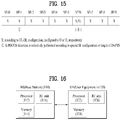
- Table 8 shows an example that Sol 3 and the aforementioned additional proposal are applied to Table 7. Shadows indicate the cases that Case #1 is applied to S SF (i.e., except E-PDCCH reception).
- FIG. 16 is a diagram for explaining an example of a base station, a relay, and a user equipment applicable to the present invention.
- a wireless communication system may include a base station (BS) 110 and a user equipment (UE) 120.
- BS base station
- UE user equipment
- the wireless communication system includes a relay
- the base station or the user equipment may be replaced by the relay.
- the base station 110 includes a processor 112, a memory 114 and a radio frequency (RF) unit 116.
- the processor 112 may be configured to implement the procedure and/or methods proposed by the present invention.
- the memory 114 is connected to the processor 112 and configured to store various information related to the operation of the processor 112.
- the RF unit 116 is connected to the processor 112 and configured to transmit and/or receive a radio signal.
- the user equipment 120 includes a processor 122, a memory 124 and a radio frequency (RF) unit 126.
- the processor 122 can be configured to implement the procedure and/or methods proposed by the present invention.
- the memory 124 is connected to the processor 122 and configured to store various information related to the operation of the processor 122.
- the RF unit 126 is connected to the processor 122 and configured to transmit and/or receive a radio signal.
- embodiments of the present invention are described centering on the signal transmission/reception relations between a relay and a base station.
- the signal transmission/reception relation identically/similarly expands to the signal transmission/reception relation between a user equipment and a base station or between a user equipment and a relay.
- a specific operation explained as performed by a base station can be occasionally performed by an upper node of the base station.
- various operations performed for communication with a user equipment can be performed by a base station or other networks except the base station.
- 'base station' may be replaced by such a terminology as a fixed station, a Node B, an eNode B (eNB), an access point, and the like.
- eNB eNode B
- UE user equipment
- UE mobile station
- MS mobile subscriber station
- Embodiments of the present invention can be implemented using various means. For instance, embodiments of the present invention can be implemented using hardware, firmware, software and/or any combinations thereof. In case of the implementation by hardware, a method according to each embodiment of the present invention can be implemented by at least one selected from the group consisting of ASICs (application specific integrated circuits), DSPs (digital signal processors), DSPDs (digital signal processing devices), PLDs (programmable logic devices), FPGAs (field programmable gate arrays), processor, controller, microcontroller, microprocessor and the like.
- ASICs application specific integrated circuits
- DSPs digital signal processors
- DSPDs digital signal processing devices
- PLDs programmable logic devices
- FPGAs field programmable gate arrays
- processor controller, microcontroller, microprocessor and the like.
- a method according to each embodiment of the present invention can be implemented by modules, procedures, and/or functions for performing the above-explained functions or operations.
- Software code is stored in a memory unit and is then drivable by a processor.
- the memory unit is provided within or outside the processor to exchange data with the processor through the means well-known to the public.
- the present invention can be used by a user equipment device, a base station, or a different device of a wireless mobile communication system. Specifically, the present invention can be applied to a method of transmitting a UL control information and apparatus therefor.
Landscapes
- Engineering & Computer Science (AREA)
- Signal Processing (AREA)
- Computer Networks & Wireless Communication (AREA)
- Mobile Radio Communication Systems (AREA)
Applications Claiming Priority (4)
| Application Number | Priority Date | Filing Date | Title |
|---|---|---|---|
| US201161549246P | 2011-10-20 | 2011-10-20 | |
| US201261678597P | 2012-08-01 | 2012-08-01 | |
| EP12841332.5A EP2688261B1 (en) | 2011-10-20 | 2012-10-22 | Method and apparatus for transmitting control information in wireless communication system |
| PCT/KR2012/008649 WO2013058623A1 (ko) | 2011-10-20 | 2012-10-22 | 무선 통신 시스템에서 제어 정보의 전송 방법 및 장치 |
Related Parent Applications (2)
| Application Number | Title | Priority Date | Filing Date |
|---|---|---|---|
| EP12841332.5A Division-Into EP2688261B1 (en) | 2011-10-20 | 2012-10-22 | Method and apparatus for transmitting control information in wireless communication system |
| EP12841332.5A Division EP2688261B1 (en) | 2011-10-20 | 2012-10-22 | Method and apparatus for transmitting control information in wireless communication system |
Publications (2)
| Publication Number | Publication Date |
|---|---|
| EP3197088A1 EP3197088A1 (en) | 2017-07-26 |
| EP3197088B1 true EP3197088B1 (en) | 2020-09-23 |
Family
ID=48441787
Family Applications (2)
| Application Number | Title | Priority Date | Filing Date |
|---|---|---|---|
| EP17160679.1A Active EP3197088B1 (en) | 2011-10-20 | 2012-10-22 | Method and apparatus for transmitting control information in wireless communication system |
| EP12841332.5A Active EP2688261B1 (en) | 2011-10-20 | 2012-10-22 | Method and apparatus for transmitting control information in wireless communication system |
Family Applications After (1)
| Application Number | Title | Priority Date | Filing Date |
|---|---|---|---|
| EP12841332.5A Active EP2688261B1 (en) | 2011-10-20 | 2012-10-22 | Method and apparatus for transmitting control information in wireless communication system |
Country Status (4)
| Country | Link |
|---|---|
| EP (2) | EP3197088B1 (es) |
| JP (2) | JP5647375B2 (es) |
| KR (1) | KR102052969B1 (es) |
| ES (1) | ES2633589T3 (es) |
Families Citing this family (4)
| Publication number | Priority date | Publication date | Assignee | Title |
|---|---|---|---|---|
| EP3100548B1 (en) * | 2014-01-31 | 2020-08-26 | Nokia Solutions and Networks Oy | A method and apparatus for enhancing a dynamic range for enhanced interference management and traffic adaptation |
| KR102026425B1 (ko) | 2015-08-21 | 2019-09-27 | 후아웨이 테크놀러지 컴퍼니 리미티드 | 무선 통신 방법, 네트워크 기기, 사용자 장비 및 시스템 |
| US10110428B2 (en) | 2015-09-24 | 2018-10-23 | Electronics And Telecommunications Research Institute | Method and apparatus for configuring frame of unlicensed band |
| KR20180007648A (ko) * | 2016-07-13 | 2018-01-23 | 삼성전자주식회사 | 무선 셀룰라 통신 시스템에서 랜덤액세스 프리앰블 송수신 방법 및 장치 |
Family Cites Families (8)
| Publication number | Priority date | Publication date | Assignee | Title |
|---|---|---|---|---|
| US8467367B2 (en) * | 2007-08-06 | 2013-06-18 | Qualcomm Incorporated | Multiplexing and transmission of traffic data and control information in a wireless communication system |
| CN101483475B (zh) * | 2008-01-07 | 2012-07-11 | 电信科学技术研究院 | 充分利用时分双工系统中特殊时隙资源的方法及装置 |
| US8780790B2 (en) * | 2008-01-07 | 2014-07-15 | Qualcomm Incorporated | TDD operation in wireless communication systems |
| US8537724B2 (en) * | 2009-03-17 | 2013-09-17 | Motorola Mobility Llc | Relay operation in a wireless communication system |
| EP2557831A4 (en) | 2010-04-06 | 2016-06-15 | Kyocera Corp | WIRELESS COMMUNICATION SYSTEM, RADIO BASE STATION AND COMMUNICATION CONTROL METHOD |
| KR101810277B1 (ko) * | 2010-09-07 | 2017-12-18 | 선 페이턴트 트러스트 | 기지국 장치, 통신 방법, 단말 장치 및 집적 회로 |
| WO2012046403A1 (ja) * | 2010-10-08 | 2012-04-12 | パナソニック株式会社 | 基地局、端末、送信方法、及び受信方法 |
| JP5784152B2 (ja) * | 2011-02-11 | 2015-09-24 | インターデイジタル パテント ホールディングス インコーポレイテッド | 拡張された制御チャネルのシステムおよび方法 |
-
2012
- 2012-10-22 KR KR1020120117223A patent/KR102052969B1/ko active IP Right Grant
- 2012-10-22 EP EP17160679.1A patent/EP3197088B1/en active Active
- 2012-10-22 EP EP12841332.5A patent/EP2688261B1/en active Active
- 2012-10-22 JP JP2014503617A patent/JP5647375B2/ja active Active
- 2012-10-22 ES ES12841332.5T patent/ES2633589T3/es active Active
-
2014
- 2014-10-31 JP JP2014223002A patent/JP6039629B2/ja active Active
Non-Patent Citations (1)
| Title |
|---|
| None * |
Also Published As
| Publication number | Publication date |
|---|---|
| KR102052969B1 (ko) | 2019-12-06 |
| JP5647375B2 (ja) | 2014-12-24 |
| EP2688261B1 (en) | 2017-04-26 |
| JP2014514843A (ja) | 2014-06-19 |
| EP2688261A4 (en) | 2015-07-01 |
| EP2688261A1 (en) | 2014-01-22 |
| JP6039629B2 (ja) | 2016-12-07 |
| ES2633589T3 (es) | 2017-09-22 |
| KR20130043600A (ko) | 2013-04-30 |
| JP2015035827A (ja) | 2015-02-19 |
| EP3197088A1 (en) | 2017-07-26 |
Similar Documents
| Publication | Publication Date | Title |
|---|---|---|
| US10334580B2 (en) | Method and apparatus for transmitting control information in wireless communication system | |
| US9532353B2 (en) | Method and apparatus for transmitting control information in wireless communication system | |
| US9374819B2 (en) | Method and device for receiving control information in wireless communication system | |
| US10142914B2 (en) | Signal transmission method for MTC and apparatus for same | |
| US10201005B2 (en) | Method for transmitting and receiving control channel and device therefor | |
| US9241328B2 (en) | Data transceiving method and apparatus for same | |
| EP2806573A1 (en) | Method of sending/receiving control information and device therefor | |
| US20150092637A1 (en) | Signal transceiving method and apparatus for same | |
| JP6068658B2 (ja) | 制御情報を送受信する方法およびそのための装置 | |
| CA2784271A1 (en) | Apparatus and method of avoiding control channel blocking | |
| US20150280882A1 (en) | Method of detecting control information in wireless communication system, and apparatus for same | |
| US20150373677A1 (en) | Method and apparatus for receiving downlink signal in wireless communication system | |
| KR101909036B1 (ko) | 신호 송수신 방법 및 이를 위한 장치 | |
| WO2015065151A1 (ko) | Mtc를 위한 신호 처리 방법 및 이를 위한 장치 | |
| EP3197088B1 (en) | Method and apparatus for transmitting control information in wireless communication system | |
| KR102201753B1 (ko) | 제어 정보를 송수신하는 방법 및 이를 위한 장치 |
Legal Events
| Date | Code | Title | Description |
|---|---|---|---|
| PUAI | Public reference made under article 153(3) epc to a published international application that has entered the european phase |
Free format text: ORIGINAL CODE: 0009012 |
|
| STAA | Information on the status of an ep patent application or granted ep patent |
Free format text: STATUS: THE APPLICATION HAS BEEN PUBLISHED |
|
| AC | Divisional application: reference to earlier application |
Ref document number: 2688261 Country of ref document: EP Kind code of ref document: P |
|
| AK | Designated contracting states |
Kind code of ref document: A1 Designated state(s): AL AT BE BG CH CY CZ DE DK EE ES FI FR GB GR HR HU IE IS IT LI LT LU LV MC MK MT NL NO PL PT RO RS SE SI SK SM TR |
|
| STAA | Information on the status of an ep patent application or granted ep patent |
Free format text: STATUS: REQUEST FOR EXAMINATION WAS MADE |
|
| 17P | Request for examination filed |
Effective date: 20180112 |
|
| RBV | Designated contracting states (corrected) |
Designated state(s): AL AT BE BG CH CY CZ DE DK EE ES FI FR GB GR HR HU IE IS IT LI LT LU LV MC MK MT NL NO PL PT RO RS SE SI SK SM TR |
|
| STAA | Information on the status of an ep patent application or granted ep patent |
Free format text: STATUS: EXAMINATION IS IN PROGRESS |
|
| 17Q | First examination report despatched |
Effective date: 20190603 |
|
| GRAP | Despatch of communication of intention to grant a patent |
Free format text: ORIGINAL CODE: EPIDOSNIGR1 |
|
| STAA | Information on the status of an ep patent application or granted ep patent |
Free format text: STATUS: GRANT OF PATENT IS INTENDED |
|
| INTG | Intention to grant announced |
Effective date: 20200401 |
|
| RIN1 | Information on inventor provided before grant (corrected) |
Inventor name: SEO, DONGYUN Inventor name: YANG, SUCKCHEL Inventor name: AHN, JOONKUI |
|
| GRAJ | Information related to disapproval of communication of intention to grant by the applicant or resumption of examination proceedings by the epo deleted |
Free format text: ORIGINAL CODE: EPIDOSDIGR1 |
|
| STAA | Information on the status of an ep patent application or granted ep patent |
Free format text: STATUS: EXAMINATION IS IN PROGRESS |
|
| INTC | Intention to grant announced (deleted) | ||
| GRAR | Information related to intention to grant a patent recorded |
Free format text: ORIGINAL CODE: EPIDOSNIGR71 |
|
| GRAS | Grant fee paid |
Free format text: ORIGINAL CODE: EPIDOSNIGR3 |
|
| STAA | Information on the status of an ep patent application or granted ep patent |
Free format text: STATUS: GRANT OF PATENT IS INTENDED |
|
| GRAA | (expected) grant |
Free format text: ORIGINAL CODE: 0009210 |
|
| STAA | Information on the status of an ep patent application or granted ep patent |
Free format text: STATUS: THE PATENT HAS BEEN GRANTED |
|
| INTG | Intention to grant announced |
Effective date: 20200813 |
|
| AC | Divisional application: reference to earlier application |
Ref document number: 2688261 Country of ref document: EP Kind code of ref document: P |
|
| AK | Designated contracting states |
Kind code of ref document: B1 Designated state(s): AL AT BE BG CH CY CZ DE DK EE ES FI FR GB GR HR HU IE IS IT LI LT LU LV MC MK MT NL NO PL PT RO RS SE SI SK SM TR |
|
| REG | Reference to a national code |
Ref country code: GB Ref legal event code: FG4D |
|
| REG | Reference to a national code |
Ref country code: CH Ref legal event code: EP |
|
| REG | Reference to a national code |
Ref country code: DE Ref legal event code: R096 Ref document number: 602012072519 Country of ref document: DE |
|
| REG | Reference to a national code |
Ref country code: IE Ref legal event code: FG4D |
|
| REG | Reference to a national code |
Ref country code: AT Ref legal event code: REF Ref document number: 1317478 Country of ref document: AT Kind code of ref document: T Effective date: 20201015 |
|
| PG25 | Lapsed in a contracting state [announced via postgrant information from national office to epo] |
Ref country code: HR Free format text: LAPSE BECAUSE OF FAILURE TO SUBMIT A TRANSLATION OF THE DESCRIPTION OR TO PAY THE FEE WITHIN THE PRESCRIBED TIME-LIMIT Effective date: 20200923 Ref country code: SE Free format text: LAPSE BECAUSE OF FAILURE TO SUBMIT A TRANSLATION OF THE DESCRIPTION OR TO PAY THE FEE WITHIN THE PRESCRIBED TIME-LIMIT Effective date: 20200923 Ref country code: BG Free format text: LAPSE BECAUSE OF FAILURE TO SUBMIT A TRANSLATION OF THE DESCRIPTION OR TO PAY THE FEE WITHIN THE PRESCRIBED TIME-LIMIT Effective date: 20201223 Ref country code: NO Free format text: LAPSE BECAUSE OF FAILURE TO SUBMIT A TRANSLATION OF THE DESCRIPTION OR TO PAY THE FEE WITHIN THE PRESCRIBED TIME-LIMIT Effective date: 20201223 Ref country code: GR Free format text: LAPSE BECAUSE OF FAILURE TO SUBMIT A TRANSLATION OF THE DESCRIPTION OR TO PAY THE FEE WITHIN THE PRESCRIBED TIME-LIMIT Effective date: 20201224 Ref country code: FI Free format text: LAPSE BECAUSE OF FAILURE TO SUBMIT A TRANSLATION OF THE DESCRIPTION OR TO PAY THE FEE WITHIN THE PRESCRIBED TIME-LIMIT Effective date: 20200923 |
|
| REG | Reference to a national code |
Ref country code: AT Ref legal event code: MK05 Ref document number: 1317478 Country of ref document: AT Kind code of ref document: T Effective date: 20200923 |
|
| PG25 | Lapsed in a contracting state [announced via postgrant information from national office to epo] |
Ref country code: RS Free format text: LAPSE BECAUSE OF FAILURE TO SUBMIT A TRANSLATION OF THE DESCRIPTION OR TO PAY THE FEE WITHIN THE PRESCRIBED TIME-LIMIT Effective date: 20200923 Ref country code: LV Free format text: LAPSE BECAUSE OF FAILURE TO SUBMIT A TRANSLATION OF THE DESCRIPTION OR TO PAY THE FEE WITHIN THE PRESCRIBED TIME-LIMIT Effective date: 20200923 |
|
| REG | Reference to a national code |
Ref country code: NL Ref legal event code: MP Effective date: 20200923 |
|
| REG | Reference to a national code |
Ref country code: LT Ref legal event code: MG4D |
|
| PG25 | Lapsed in a contracting state [announced via postgrant information from national office to epo] |
Ref country code: SM Free format text: LAPSE BECAUSE OF FAILURE TO SUBMIT A TRANSLATION OF THE DESCRIPTION OR TO PAY THE FEE WITHIN THE PRESCRIBED TIME-LIMIT Effective date: 20200923 Ref country code: EE Free format text: LAPSE BECAUSE OF FAILURE TO SUBMIT A TRANSLATION OF THE DESCRIPTION OR TO PAY THE FEE WITHIN THE PRESCRIBED TIME-LIMIT Effective date: 20200923 Ref country code: LT Free format text: LAPSE BECAUSE OF FAILURE TO SUBMIT A TRANSLATION OF THE DESCRIPTION OR TO PAY THE FEE WITHIN THE PRESCRIBED TIME-LIMIT Effective date: 20200923 Ref country code: CZ Free format text: LAPSE BECAUSE OF FAILURE TO SUBMIT A TRANSLATION OF THE DESCRIPTION OR TO PAY THE FEE WITHIN THE PRESCRIBED TIME-LIMIT Effective date: 20200923 Ref country code: RO Free format text: LAPSE BECAUSE OF FAILURE TO SUBMIT A TRANSLATION OF THE DESCRIPTION OR TO PAY THE FEE WITHIN THE PRESCRIBED TIME-LIMIT Effective date: 20200923 Ref country code: PT Free format text: LAPSE BECAUSE OF FAILURE TO SUBMIT A TRANSLATION OF THE DESCRIPTION OR TO PAY THE FEE WITHIN THE PRESCRIBED TIME-LIMIT Effective date: 20210125 |
|
| PG25 | Lapsed in a contracting state [announced via postgrant information from national office to epo] |
Ref country code: IS Free format text: LAPSE BECAUSE OF FAILURE TO SUBMIT A TRANSLATION OF THE DESCRIPTION OR TO PAY THE FEE WITHIN THE PRESCRIBED TIME-LIMIT Effective date: 20210123 Ref country code: PL Free format text: LAPSE BECAUSE OF FAILURE TO SUBMIT A TRANSLATION OF THE DESCRIPTION OR TO PAY THE FEE WITHIN THE PRESCRIBED TIME-LIMIT Effective date: 20200923 Ref country code: ES Free format text: LAPSE BECAUSE OF FAILURE TO SUBMIT A TRANSLATION OF THE DESCRIPTION OR TO PAY THE FEE WITHIN THE PRESCRIBED TIME-LIMIT Effective date: 20200923 Ref country code: AL Free format text: LAPSE BECAUSE OF FAILURE TO SUBMIT A TRANSLATION OF THE DESCRIPTION OR TO PAY THE FEE WITHIN THE PRESCRIBED TIME-LIMIT Effective date: 20200923 Ref country code: AT Free format text: LAPSE BECAUSE OF FAILURE TO SUBMIT A TRANSLATION OF THE DESCRIPTION OR TO PAY THE FEE WITHIN THE PRESCRIBED TIME-LIMIT Effective date: 20200923 |
|
| REG | Reference to a national code |
Ref country code: CH Ref legal event code: PL |
|
| REG | Reference to a national code |
Ref country code: DE Ref legal event code: R097 Ref document number: 602012072519 Country of ref document: DE |
|
| PG25 | Lapsed in a contracting state [announced via postgrant information from national office to epo] |
Ref country code: LU Free format text: LAPSE BECAUSE OF NON-PAYMENT OF DUE FEES Effective date: 20201022 Ref country code: SK Free format text: LAPSE BECAUSE OF FAILURE TO SUBMIT A TRANSLATION OF THE DESCRIPTION OR TO PAY THE FEE WITHIN THE PRESCRIBED TIME-LIMIT Effective date: 20200923 Ref country code: MC Free format text: LAPSE BECAUSE OF FAILURE TO SUBMIT A TRANSLATION OF THE DESCRIPTION OR TO PAY THE FEE WITHIN THE PRESCRIBED TIME-LIMIT Effective date: 20200923 |
|
| REG | Reference to a national code |
Ref country code: BE Ref legal event code: MM Effective date: 20201031 |
|
| PLBE | No opposition filed within time limit |
Free format text: ORIGINAL CODE: 0009261 |
|
| STAA | Information on the status of an ep patent application or granted ep patent |
Free format text: STATUS: NO OPPOSITION FILED WITHIN TIME LIMIT |
|
| PG25 | Lapsed in a contracting state [announced via postgrant information from national office to epo] |
Ref country code: CH Free format text: LAPSE BECAUSE OF NON-PAYMENT OF DUE FEES Effective date: 20201031 Ref country code: BE Free format text: LAPSE BECAUSE OF NON-PAYMENT OF DUE FEES Effective date: 20201031 Ref country code: DK Free format text: LAPSE BECAUSE OF FAILURE TO SUBMIT A TRANSLATION OF THE DESCRIPTION OR TO PAY THE FEE WITHIN THE PRESCRIBED TIME-LIMIT Effective date: 20200923 Ref country code: LI Free format text: LAPSE BECAUSE OF NON-PAYMENT OF DUE FEES Effective date: 20201031 Ref country code: SI Free format text: LAPSE BECAUSE OF FAILURE TO SUBMIT A TRANSLATION OF THE DESCRIPTION OR TO PAY THE FEE WITHIN THE PRESCRIBED TIME-LIMIT Effective date: 20200923 |
|
| 26N | No opposition filed |
Effective date: 20210624 |
|
| PG25 | Lapsed in a contracting state [announced via postgrant information from national office to epo] |
Ref country code: IT Free format text: LAPSE BECAUSE OF FAILURE TO SUBMIT A TRANSLATION OF THE DESCRIPTION OR TO PAY THE FEE WITHIN THE PRESCRIBED TIME-LIMIT Effective date: 20200923 Ref country code: IE Free format text: LAPSE BECAUSE OF NON-PAYMENT OF DUE FEES Effective date: 20201022 |
|
| PG25 | Lapsed in a contracting state [announced via postgrant information from national office to epo] |
Ref country code: TR Free format text: LAPSE BECAUSE OF FAILURE TO SUBMIT A TRANSLATION OF THE DESCRIPTION OR TO PAY THE FEE WITHIN THE PRESCRIBED TIME-LIMIT Effective date: 20200923 Ref country code: MT Free format text: LAPSE BECAUSE OF FAILURE TO SUBMIT A TRANSLATION OF THE DESCRIPTION OR TO PAY THE FEE WITHIN THE PRESCRIBED TIME-LIMIT Effective date: 20200923 Ref country code: CY Free format text: LAPSE BECAUSE OF FAILURE TO SUBMIT A TRANSLATION OF THE DESCRIPTION OR TO PAY THE FEE WITHIN THE PRESCRIBED TIME-LIMIT Effective date: 20200923 |
|
| PG25 | Lapsed in a contracting state [announced via postgrant information from national office to epo] |
Ref country code: MK Free format text: LAPSE BECAUSE OF FAILURE TO SUBMIT A TRANSLATION OF THE DESCRIPTION OR TO PAY THE FEE WITHIN THE PRESCRIBED TIME-LIMIT Effective date: 20200923 |
|
| P01 | Opt-out of the competence of the unified patent court (upc) registered |
Effective date: 20230524 |
|
| PG25 | Lapsed in a contracting state [announced via postgrant information from national office to epo] |
Ref country code: NL Free format text: LAPSE BECAUSE OF NON-PAYMENT OF DUE FEES Effective date: 20200923 |
|
| PGFP | Annual fee paid to national office [announced via postgrant information from national office to epo] |
Ref country code: GB Payment date: 20230905 Year of fee payment: 12 |
|
| PGFP | Annual fee paid to national office [announced via postgrant information from national office to epo] |
Ref country code: FR Payment date: 20230905 Year of fee payment: 12 |
|
| PGFP | Annual fee paid to national office [announced via postgrant information from national office to epo] |
Ref country code: DE Payment date: 20230905 Year of fee payment: 12 |