EP3196846A1 - Correction device and automated teller machine - Google Patents
Correction device and automated teller machine Download PDFInfo
- Publication number
- EP3196846A1 EP3196846A1 EP15842851.6A EP15842851A EP3196846A1 EP 3196846 A1 EP3196846 A1 EP 3196846A1 EP 15842851 A EP15842851 A EP 15842851A EP 3196846 A1 EP3196846 A1 EP 3196846A1
- Authority
- EP
- European Patent Office
- Prior art keywords
- deflection correcting
- wheels
- banknote
- deflection
- reference side
- Prior art date
- Legal status (The legal status is an assumption and is not a legal conclusion. Google has not performed a legal analysis and makes no representation as to the accuracy of the status listed.)
- Granted
Links
- 230000007246 mechanism Effects 0.000 claims abstract description 42
- 230000005540 biological transmission Effects 0.000 claims description 44
- 230000001360 synchronised effect Effects 0.000 claims description 21
- 238000000151 deposition Methods 0.000 claims description 8
- 238000000034 method Methods 0.000 abstract description 12
- 230000008569 process Effects 0.000 abstract description 11
- 238000013459 approach Methods 0.000 abstract 1
- 230000009471 action Effects 0.000 description 11
- 230000008901 benefit Effects 0.000 description 3
- 238000012986 modification Methods 0.000 description 2
- 230000004048 modification Effects 0.000 description 2
- 238000006467 substitution reaction Methods 0.000 description 2
- 230000002411 adverse Effects 0.000 description 1
- 230000009286 beneficial effect Effects 0.000 description 1
- 238000000926 separation method Methods 0.000 description 1
Images


Classifications
-
- B—PERFORMING OPERATIONS; TRANSPORTING
- B65—CONVEYING; PACKING; STORING; HANDLING THIN OR FILAMENTARY MATERIAL
- B65H—HANDLING THIN OR FILAMENTARY MATERIAL, e.g. SHEETS, WEBS, CABLES
- B65H9/00—Registering, e.g. orientating, articles; Devices therefor
- B65H9/16—Inclined tape, roller, or like article-forwarding side registers
-
- G—PHYSICS
- G07—CHECKING-DEVICES
- G07D—HANDLING OF COINS OR VALUABLE PAPERS, e.g. TESTING, SORTING BY DENOMINATIONS, COUNTING, DISPENSING, CHANGING OR DEPOSITING
- G07D11/00—Devices accepting coins; Devices accepting, dispensing, sorting or counting valuable papers
-
- B—PERFORMING OPERATIONS; TRANSPORTING
- B65—CONVEYING; PACKING; STORING; HANDLING THIN OR FILAMENTARY MATERIAL
- B65H—HANDLING THIN OR FILAMENTARY MATERIAL, e.g. SHEETS, WEBS, CABLES
- B65H9/00—Registering, e.g. orientating, articles; Devices therefor
- B65H9/16—Inclined tape, roller, or like article-forwarding side registers
- B65H9/166—Roller
-
- G—PHYSICS
- G07—CHECKING-DEVICES
- G07D—HANDLING OF COINS OR VALUABLE PAPERS, e.g. TESTING, SORTING BY DENOMINATIONS, COUNTING, DISPENSING, CHANGING OR DEPOSITING
- G07D11/00—Devices accepting coins; Devices accepting, dispensing, sorting or counting valuable papers
- G07D11/10—Mechanical details
- G07D11/16—Handling of valuable papers
-
- G—PHYSICS
- G07—CHECKING-DEVICES
- G07D—HANDLING OF COINS OR VALUABLE PAPERS, e.g. TESTING, SORTING BY DENOMINATIONS, COUNTING, DISPENSING, CHANGING OR DEPOSITING
- G07D11/00—Devices accepting coins; Devices accepting, dispensing, sorting or counting valuable papers
- G07D11/10—Mechanical details
- G07D11/16—Handling of valuable papers
- G07D11/17—Aligning
-
- G—PHYSICS
- G07—CHECKING-DEVICES
- G07F—COIN-FREED OR LIKE APPARATUS
- G07F19/00—Complete banking systems; Coded card-freed arrangements adapted for dispensing or receiving monies or the like and posting such transactions to existing accounts, e.g. automatic teller machines
- G07F19/20—Automatic teller machines [ATMs]
-
- B—PERFORMING OPERATIONS; TRANSPORTING
- B65—CONVEYING; PACKING; STORING; HANDLING THIN OR FILAMENTARY MATERIAL
- B65H—HANDLING THIN OR FILAMENTARY MATERIAL, e.g. SHEETS, WEBS, CABLES
- B65H2301/00—Handling processes for sheets or webs
- B65H2301/30—Orientation, displacement, position of the handled material
- B65H2301/31—Features of transport path
- B65H2301/312—Features of transport path for transport path involving at least two planes of transport forming an angle between each other
- B65H2301/3122—U-shaped
-
- B—PERFORMING OPERATIONS; TRANSPORTING
- B65—CONVEYING; PACKING; STORING; HANDLING THIN OR FILAMENTARY MATERIAL
- B65H—HANDLING THIN OR FILAMENTARY MATERIAL, e.g. SHEETS, WEBS, CABLES
- B65H2301/00—Handling processes for sheets or webs
- B65H2301/30—Orientation, displacement, position of the handled material
- B65H2301/33—Modifying, selecting, changing orientation
- B65H2301/331—Skewing, correcting skew, i.e. changing slightly orientation of material
-
- B—PERFORMING OPERATIONS; TRANSPORTING
- B65—CONVEYING; PACKING; STORING; HANDLING THIN OR FILAMENTARY MATERIAL
- B65H—HANDLING THIN OR FILAMENTARY MATERIAL, e.g. SHEETS, WEBS, CABLES
- B65H2301/00—Handling processes for sheets or webs
- B65H2301/40—Type of handling process
- B65H2301/44—Moving, forwarding, guiding material
- B65H2301/442—Moving, forwarding, guiding material by acting on edge of handled material
- B65H2301/4422—Moving, forwarding, guiding material by acting on edge of handled material with guide member moving in the material direction
-
- B—PERFORMING OPERATIONS; TRANSPORTING
- B65—CONVEYING; PACKING; STORING; HANDLING THIN OR FILAMENTARY MATERIAL
- B65H—HANDLING THIN OR FILAMENTARY MATERIAL, e.g. SHEETS, WEBS, CABLES
- B65H2301/00—Handling processes for sheets or webs
- B65H2301/40—Type of handling process
- B65H2301/44—Moving, forwarding, guiding material
- B65H2301/447—Moving, forwarding, guiding material transferring material between transport devices
- B65H2301/4475—Rotary or endless transport devices having elements acting on edge of articles
-
- B—PERFORMING OPERATIONS; TRANSPORTING
- B65—CONVEYING; PACKING; STORING; HANDLING THIN OR FILAMENTARY MATERIAL
- B65H—HANDLING THIN OR FILAMENTARY MATERIAL, e.g. SHEETS, WEBS, CABLES
- B65H2404/00—Parts for transporting or guiding the handled material
- B65H2404/10—Rollers
- B65H2404/11—Details of cross-section or profile
- B65H2404/111—Details of cross-section or profile shape
- B65H2404/1116—Polygonal cross-section
-
- B—PERFORMING OPERATIONS; TRANSPORTING
- B65—CONVEYING; PACKING; STORING; HANDLING THIN OR FILAMENTARY MATERIAL
- B65H—HANDLING THIN OR FILAMENTARY MATERIAL, e.g. SHEETS, WEBS, CABLES
- B65H2404/00—Parts for transporting or guiding the handled material
- B65H2404/20—Belts
- B65H2404/26—Particular arrangement of belt, or belts
- B65H2404/267—Arrangement of belt(s) in edge contact with handled material
-
- B—PERFORMING OPERATIONS; TRANSPORTING
- B65—CONVEYING; PACKING; STORING; HANDLING THIN OR FILAMENTARY MATERIAL
- B65H—HANDLING THIN OR FILAMENTARY MATERIAL, e.g. SHEETS, WEBS, CABLES
- B65H2404/00—Parts for transporting or guiding the handled material
- B65H2404/70—Other elements in edge contact with handled material, e.g. registering, orientating, guiding devices
- B65H2404/74—Guiding means
- B65H2404/741—Guiding means movable in operation
-
- B—PERFORMING OPERATIONS; TRANSPORTING
- B65—CONVEYING; PACKING; STORING; HANDLING THIN OR FILAMENTARY MATERIAL
- B65H—HANDLING THIN OR FILAMENTARY MATERIAL, e.g. SHEETS, WEBS, CABLES
- B65H2404/00—Parts for transporting or guiding the handled material
- B65H2404/70—Other elements in edge contact with handled material, e.g. registering, orientating, guiding devices
- B65H2404/74—Guiding means
- B65H2404/743—Guiding means for guiding longitudinally
-
- B—PERFORMING OPERATIONS; TRANSPORTING
- B65—CONVEYING; PACKING; STORING; HANDLING THIN OR FILAMENTARY MATERIAL
- B65H—HANDLING THIN OR FILAMENTARY MATERIAL, e.g. SHEETS, WEBS, CABLES
- B65H2701/00—Handled material; Storage means
- B65H2701/10—Handled articles or webs
- B65H2701/19—Specific article or web
- B65H2701/1912—Banknotes, bills and cheques or the like
Definitions
- the present application relates to the technical field of automatic teller machines, and in particular to a deflection correcting device and an automatic teller machine.
- banknotes In the process of depositing banknotes into an ATM (Automated Teller Machine), the banknotes are apt to deflect when being put into a banknote depositing port of the ATM by a customer.
- the deflected banknotes enter a banknote depositing core or a banknote box of the ATM, errors such as being unidentifiable or a jamming may occur and thus a normal operation of the machine is adversely affected. Therefore, the entered banknotes are required to be performed with the deflection correcting.
- a deflection correcting device In a conventional deflection correcting device, multiple deflection correcting wheels are provided in a banknote running passage, and these deflection correcting wheels move banknotes in the banknote running passage towards one side (a reference wall) of the passage.
- a deflection correction to the banknotes are realized when the banknotes leave the passage.
- the banknotes hit the reference wall and the reference wall intercepts the banknotes, if the banknotes are required to fit with the reference wall and keep moving, the banknotes should have sufficient rigidity. In a case that the banknotes are old banknotes, a phenomenon that the banknotes are jammed in the reference walls and the passage during the deflection correcting process, is apt to occur.
- a deflection correcting device and an automatic teller machine are provided according to the embodiments of the present application, which can realize a deflection correcting for banknotes and prevent the banknotes from jamming at a reference wall and a passage during a process of deflection correcting.
- the deflection correcting device includes a banknote running passage defined by a first passage plate and a second passage plate, deflection correcting wheels are arranged in the banknote running passage and a deflection correcting direction of the deflection correcting wheels is deflected from a reference side of the banknote running passage, a plurality of the deflection correcting wheels are dispersedly arranged in a transmission direction of the banknote running passage and are gradually close to the reference side, wherein a lateral guiding mechanism is provided at the reference side, and configured to drive a banknote that reaches the reference side to move in the transmission direction of the banknote running passage; and a deflection correcting adjusting wheel is provided at a tail end in a deflection direction of the plurality of the deflection correcting wheels and is close to the reference side, and a deflection correcting direction of the deflection correcting adjusting wheel is deflected from the reference side.
- the lateral guiding mechanism includes a power shaft, two conical wheels and a turning belt; the turning belt is installed between the two conical wheels; the power shaft fixedly passes through one of the two conical wheels and is configured to drive the conical wheel to rotate; and the turning belt is arranged on the reference side and has a running direction coincident with the transmission direction.
- the lateral guiding mechanism further includes a plurality of pinch rollers and a plurality of tensioning wheels; the pinch roller are in a press fit with the conical wheels respectively; and the tensioning wheels are installed at inner sides of the turning belt and is configured to assist the turning belt to transmit
- a surface moving speed of the turning belt is coincident with a speed of the banknote moving forward.
- the lateral guiding mechanism includes a turntable transmission shaft and a guiding turntable; the turntable transmission shaft fixedly passes through the guiding turntable and is configured to drive the guiding turntable to rotate; and a surface of the guiding turntable is arranged on the reference side and a running direction of the surface of the guiding turntable is coincident with the transmission direction.
- the lateral guiding mechanism includes a driving wheel, a plurality of driven wheels and a synchronous belt; the synchronous belt is installed on the driving wheel and the plurality of driven wheels; the driving wheel is configured to drive the synchronous belt and the plurality of driven wheels; and a lateral side of the synchronous belt is arranged on the reference side and a running direction of the synchronous belt is coincident with the transmission direction.
- the deflection correcting adjusting wheel is a polygonal adjusting wheel.
- a linear velocity of a maximum diameter of the deflection correcting adjusting wheel is coincident with a linear velocity of the deflection correcting wheels.
- the deflection correcting wheels are arranged in a middle portion of the banknote running passage and include three rows of deflection correcting wheels, and deflection correcting directions of the three rows of deflection correcting wheels are the same; the three rows of deflection correcting wheels are respectively a first row of deflection correcting wheel, a second row of deflection correcting wheel and a third row of deflection correcting wheel in the transmission direction, deflection correcting floating wheels are arranged on the banknote running passage and in a press fit with the deflection correcting wheels respectively; pressures applied on the three rows of deflection correcting wheels by the deflection correcting floating wheels are a first row pressure, a second row pressure and a third row pressure respectively; and the second row pressure is larger than the third row pressure, and the third row pressure is larger than the first row pressure.
- an automatic banknote depositing device is provided with the above-mentioned deflection correcting device.
- the embodiments of the present application have the following advantages.
- a deflection correcting device includes a banknote running passage defined by a first passage plate and a second passage plate, deflection correcting wheels are arranged in the banknote running passage and a deflection correcting direction of the deflection correcting wheels is deflected from a reference side of the banknote running passage, a plurality of the deflection correcting wheels are dispersedly arranged in a transmission direction of the banknote running passage and are gradually close to the reference side, a lateral guiding mechanism is provided at the reference side, and configured to drive a banknote that reaches the reference side to move in the transmission direction of the banknote running passage; and a deflection correcting adjusting wheel is provided at a tail end in a deflection direction of the plurality of the deflection correcting wheels and is close to the reference side, and a deflection correcting direction of the deflection correcting adjusting wheel is deflected from the reference side.
- the banknote first gradually gets close to the reference side under the action of the deflection correcting wheels, and after the banknote reaches the reference side, the banknote is driven to move forward by the lateral guiding mechanism and in this case a phenomenon that the head portion of the banknote deflects from the reference side may occur.
- the head portion of the banknote deflects
- the head portion of the banknote is adjusted to be close to the reference side again by the deflection correcting adjusting wheel arranged at the tail end, and the banknote is re-adjusted and a deflection correction is realized, therefore even the rigidity of the banknote is insufficient, the banknote can be driven by the lateral guiding mechanism to fit with the reference side and thus is prevented from jamming at the reference side and the passage during the deflection correcting process.
- a deflection correcting device and an automatic teller machine are provided according to the embodiments of the present application, and are configured to realize a deflection correcting of banknotes and prevent the banknotes from jamming in reference walls and a passage during a process of deflection correcting.
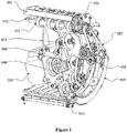
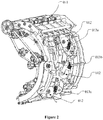
- Figs. 1 and 2 are schematic views showing a three-dimensional structure of the deflection correcting device according to an embodiment of the present application, and the deflection correcting device includes a first passage plate 001, a second passage plate 002, a transmission shaft 003, deflection correcting wheels 004, an electric motor 005, a first gear 006, a driving belt 007, a second gear 008, a lateral guiding mechanism 009, a deflection correcting adjusting wheel 010, a transmission shaft floating wheel 011, a deflection correcting floating wheel 012 and a deflection correcting wheel pressure spring 013.
- an area a mentioned hereinafter refers to a banknote separation mechanism arranged in front of the deflection correcting device
- an area b refers to a banknote conveying mechanism arranged at a tail end of the deflection correcting device.
- Fig. 3 shows one structure of the lateral guiding mechanism 009, i.e., a turning belt guiding mechanism which includes a power shaft 014, a pinch roller 015, a conical wheel 016, a turning belt 017 and a tensioning wheel 018.
- a turning belt guiding mechanism which includes a power shaft 014, a pinch roller 015, a conical wheel 016, a turning belt 017 and a tensioning wheel 018.
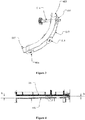
- Fig. 4 is a sectional view of a banknote running passage, in which H represents a wide distance of the passage and h represents a narrow distance of the passage.
- Fig. 5 is a schematic view showing the structure of the turning belt.
- Fig. 6 shows one structure of the lateral guiding mechanism 009, i.e., a guiding turntable mechanism which includes a guiding turntable 020 and a turntable transmission shaft 024.
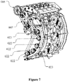
- Fig. 7 shows one structure of the lateral guiding mechanism 009, i.e., a guiding synchronous belt mechanism which includes a driving wheel 021, a driven wheel 022 and a synchronous belt 023.
- the structure of the deflection correcting device is described as follows.
- a banknote running passage which allows the banknotes to pass, is formed by the first passage plate 001 and the second passage plate 002.
- the banknote running passage is a passage having a cross section with a variable width along a banknote running direction.
- h is a passage side close to one side (a reference side) of the lateral guiding mechanism
- H is a passage side away from the reference side, wherein H>h>0.8mm.
- each transmission shaft floating wheel 011 is in a press fit with each transmission wheel on the transmission shaft 003 and is in a one-to-one correspondence with the transmission wheel.
- a spring or other elastic part acts on the transmission shaft floating wheel 011, thus an object of clamping and conveying the banknotes can be realized, and power of the transmission wheel is transferred from the area a by the first gear 006.
- the deflection correcting device is provided with several groups of the deflection correcting wheels 004, which are driven by the electric motor 005.
- the deflection correcting wheels 004 there are three groups of the deflection correcting wheels 004 in this embodiment.
- Each group of the deflection correcting wheels 004 extends into the banknote running passage defined by the first passage plate 001 and the second passage plate 002, a top surface of each deflection correcting wheel 004 is pressed by the deflection correcting floating wheel 012, and the deflection correcting floating wheel 012 is under the action of a deflection correcting wheel pressure spring 013 and forms different pressures.
- one end of the turning belt guiding mechanism 009 which end is close to an end of the passage with a distance of h, functions as a reference side of banknotes deflection correcting.
- a moving direction of the turning belt which functions as the reference side, should be coincident with the banknote running direction and should have a surface moving speed which is coincident with a speed of the banknote moving forward.
- the turning belt 017 may circularly rotate under the action of the conical wheel 016 driven by the power shaft 014, and power of the power shaft 014 is transferred by the first gear 006, the driving belt 007 and the second gear 008 from the area a (the banknote separating mechanism in front of the deflection correct device).
- a certain number of pinch rollers 015 and tensioning wheels 018 may be provided in the transmission mechanism to assist transmission.
- the deflection correcting adjusting wheel 010 may be a pentagonal wheel, a gap of 0.1 mm should be provided between an outer diameter of the deflection correcting adjusting wheel 010 and the first passage plate 001, and an arrangement angle of the deflection correcting adjusting wheel 010 should be coincident with an arrangement angle of the deflection correcting wheel 004.
- the power of the deflection correcting adjusting wheel 010 is also provided by the electric motor 005 and has a maximum diameter, a linear velocity of the maximum diameter is coincident with a linear velocity of the deflection correcting wheel 004.
- the lateral guiding mechanism 009 is not limited to the turning belt guiding mechanism, and any mechanism that can rotate and generate a forward friction force to the banknotes is feasible, for example a turntable and a synchronous belt, and the lateral guiding mechanism 009 is not limited herein.
- the banknote After being separated from the banknote separating mechanism at the area a, the banknote is clamped and conveyed forward by the transmission shaft 003.
- the deflection correcting wheel 004 When the banknote reaches the first group of deflection correcting wheel 004, the deflection correcting wheel 004 generates a lateral force towards the reference side to the banknote.
- a clamping force generated by the transmission shaft floating wheel 011 and the transmission shaft 003 is larger than a clamping force generated by the deflection correcting wheel 004 and the deflection correcting floating wheel 012, and the deflection correcting wheel 004 is close to the transmission shaft 003, the lateral force generated by first group of deflection correcting wheel 004 cannot drive the banknote toward the reference side yet.
- the banknote When the banknote continues to move forward and reaches the third group of deflection correcting wheel 004, the banknote is subjected to a larger lateral force and is closer to the reference side.
- the action of deflection correcting continues, one corner of the banknote firstly reaches the reference side firstly because the banknote gets close to the reference side obliquely.
- the turning belt 017 since the turning belt 017 has been rotated already, a forward friction force is generated, by the turning belt 017, to the corner of the banknote that reaches the reference side, and thus the banknote is driven to move forward and is unlikely to be bent here to cause a jamming.
- a head portion of banknote has already been corrected in place.
- the action of deflection correcting is still performed on a tail portion of the banknote, and furthermore because of the action of the friction force of the passage, a phenomenon occurs that the head portion of the banknote generates a certain deflection relative to the reference side.
- a group of deflection correcting adjusting wheel 010 is required to be provided.
- the deflection correcting adjusting wheel 010 may be a pentagonal wheel, and a lateral force is intermittently generated during a rotating process, therefore the head portion of the banknote which deflects from the reference side is allowed to get close to the reference side again.
- the head portion of the banknote may enter the area b and is clamped and conveyed forward by a driving wheel of a conveying mechanism.
- the tail portion of the banknote leaves the deflection correcting adjusting wheel 010, the entire action of deflection correcting is finished.
- the working process of the deflection correcting device is almost the same as that described above, and thus will not be described herein.
- the working principle of the guiding turntable and the guiding synchronous belt will be briefly described hereinafter.
- a turntable transmission shaft 024 is rotated by the power transmitted by the first gear 006 and the driving belt 007, thus a guiding turntable 020 fixed on the turntable transmission shaft 024 is driven to rotate.
- the turntable driving wheel and the guiding turntable 020 are required to be arranged reasonably, to allow a linear velocity of a surface of the guiding turntable 020, which surface is close to the reference side, is coincident with a velocity of the banknote moving forward, and a moving direction is coincident with a transmission direction after the guiding turntable 020 rotates.
- a driving wheel 021 is rotated by the power transmitted by the first gear 006 and the driving belt 007, thus a synchronous belt 023 fixed on the driving wheel 021 is driven to rotate, and the synchronous belt 023 further drives driven wheels 022 to rotate together.
- the driving wheel 021, the driven wheel 022 and the synchronous belt 023 are required to be arranged reasonably, to allow a linear velocity of a surface of the synchronous belt 023, which surface is close to the reference side, is coincident with a velocity of the banknote moving forward, and a moving direction is coincident with a transmission direction after the synchronous belt 023 rotates.
- a deflection correcting device includes a banknote running passage defined by a first passage plate 001 and a second passage plate 002, and deflection correcting wheels 004 are arranged in the banknote running passage and a deflection correcting direction of the deflection correcting wheels 004 is deflected from a reference side of the banknote running passage.
- a plurality of the deflection correcting wheels 004 are dispersedly arranged in a transmission direction of the banknote running passage and are gradually close to the reference side.
- the reference side is provided with a lateral guiding mechanism 009 configured to drive the banknote that reaches the reference side to move in the transmission direction of the banknote running passage.
- a deflection correcting adjusting wheel 010 is provided at a tail end in a deflection direction of a plurality of the deflection correcting wheels 004 and is close to the reference side, and a deflection direction of the deflection correcting adjusting wheel 010 is deflected from the reference side.
- the banknote first gradually gets close to the reference side under the action of the deflection correcting wheels 004, and after the banknote reaches the reference side, the banknote is driven to move forward by the lateral guiding mechanism 009 and in this case a phenomenon that the head portion of the banknote deflects from the reference side may occur.
- the head portion of the banknote deflects
- the head portion of the banknote is adjusted to be close to the reference side again by the deflection correcting adjusting wheel 010 arranged at the tail end, and the banknote is re-adjusted and a deflection correction is realized, therefore even the rigidity of the banknote is insufficient, the banknote can be driven by the lateral guiding mechanism 009 to fit with the reference side and thus is prevented from jamming at the reference side and the passage during the deflection correcting process.
- an automatic teller machine is further provided by the present application, which is provided with an automatic banknote depositing device and a deflection correcting device is provided in the automatic banknote depositing device, the deflection correcting device is the deflection correcting device according to the above embodiments.
Landscapes
- Physics & Mathematics (AREA)
- General Physics & Mathematics (AREA)
- Business, Economics & Management (AREA)
- Accounting & Taxation (AREA)
- Finance (AREA)
- Engineering & Computer Science (AREA)
- Mechanical Engineering (AREA)
- Registering Or Overturning Sheets (AREA)
Abstract
Description
- The present application claims the benefit of priority to Chinese patent application No.
201410476293.0 - The present application relates to the technical field of automatic teller machines, and in particular to a deflection correcting device and an automatic teller machine.
- In the process of depositing banknotes into an ATM (Automated Teller Machine), the banknotes are apt to deflect when being put into a banknote depositing port of the ATM by a customer. When the deflected banknotes enter a banknote depositing core or a banknote box of the ATM, errors such as being unidentifiable or a jamming may occur and thus a normal operation of the machine is adversely affected. Therefore, the entered banknotes are required to be performed with the deflection correcting.
- In a conventional deflection correcting device, multiple deflection correcting wheels are provided in a banknote running passage, and these deflection correcting wheels move banknotes in the banknote running passage towards one side (a reference wall) of the passage. When the banknotes hit the reference wall, because of an interception action from the reference wall to the banknotes and a forward transmission action from a transmission wheel in the passage, a deflection correction to the banknotes are realized when the banknotes leave the passage.
- However, when the banknotes hit the reference wall and the reference wall intercepts the banknotes, if the banknotes are required to fit with the reference wall and keep moving, the banknotes should have sufficient rigidity. In a case that the banknotes are old banknotes, a phenomenon that the banknotes are jammed in the reference walls and the passage during the deflection correcting process, is apt to occur.
- A deflection correcting device and an automatic teller machine are provided according to the embodiments of the present application, which can realize a deflection correcting for banknotes and prevent the banknotes from jamming at a reference wall and a passage during a process of deflection correcting.
- The deflection correcting device according to the embodiments of the present application includes a banknote running passage defined by a first passage plate and a second passage plate, deflection correcting wheels are arranged in the banknote running passage and a deflection correcting direction of the deflection correcting wheels is deflected from a reference side of the banknote running passage, a plurality of the deflection correcting wheels are dispersedly arranged in a transmission direction of the banknote running passage and are gradually close to the reference side, wherein
a lateral guiding mechanism is provided at the reference side, and configured to drive a banknote that reaches the reference side to move in the transmission direction of the banknote running passage; and
a deflection correcting adjusting wheel is provided at a tail end in a deflection direction of the plurality of the deflection correcting wheels and is close to the reference side, and a deflection correcting direction of the deflection correcting adjusting wheel is deflected from the reference side. - Optionally, the lateral guiding mechanism includes a power shaft, two conical wheels and a turning belt; the turning belt is installed between the two conical wheels; the power shaft fixedly passes through one of the two conical wheels and is configured to drive the conical wheel to rotate; and the turning belt is arranged on the reference side and has a running direction coincident with the transmission direction.
- Optionally, the lateral guiding mechanism further includes a plurality of pinch rollers and a plurality of tensioning wheels;
the pinch roller are in a press fit with the conical wheels respectively; and
the tensioning wheels are installed at inner sides of the turning belt and is configured to assist the turning belt to transmit - Optionally, a surface moving speed of the turning belt is coincident with a speed of the banknote moving forward.
- Optionally, the lateral guiding mechanism includes a turntable transmission shaft and a guiding turntable; the turntable transmission shaft fixedly passes through the guiding turntable and is configured to drive the guiding turntable to rotate; and a surface of the guiding turntable is arranged on the reference side and a running direction of the surface of the guiding turntable is coincident with the transmission direction.
- Optionally, the lateral guiding mechanism includes a driving wheel, a plurality of driven wheels and a synchronous belt; the synchronous belt is installed on the driving wheel and the plurality of driven wheels; the driving wheel is configured to drive the synchronous belt and the plurality of driven wheels; and a lateral side of the synchronous belt is arranged on the reference side and a running direction of the synchronous belt is coincident with the transmission direction.
- Optionally, the deflection correcting adjusting wheel is a polygonal adjusting wheel.
- Optionally, a linear velocity of a maximum diameter of the deflection correcting adjusting wheel is coincident with a linear velocity of the deflection correcting wheels.
- Optionally, the deflection correcting wheels are arranged in a middle portion of the banknote running passage and include three rows of deflection correcting wheels, and deflection correcting directions of the three rows of deflection correcting wheels are the same;
the three rows of deflection correcting wheels are respectively a first row of deflection correcting wheel, a second row of deflection correcting wheel and a third row of deflection correcting wheel in the transmission direction, deflection correcting floating wheels are arranged on the banknote running passage and in a press fit with the deflection correcting wheels respectively;
pressures applied on the three rows of deflection correcting wheels by the deflection correcting floating wheels are a first row pressure, a second row pressure and a third row pressure respectively; and
the second row pressure is larger than the third row pressure, and the third row pressure is larger than the first row pressure. - Optionally, an automatic banknote depositing device is provided with the above-mentioned deflection correcting device.
- According to the above technical solutions, the embodiments of the present application have the following advantages.
- In the embodiments of the present application, a deflection correcting device includes a banknote running passage defined by a first passage plate and a second passage plate, deflection correcting wheels are arranged in the banknote running passage and a deflection correcting direction of the deflection correcting wheels is deflected from a reference side of the banknote running passage, a plurality of the deflection correcting wheels are dispersedly arranged in a transmission direction of the banknote running passage and are gradually close to the reference side, a lateral guiding mechanism is provided at the reference side, and configured to drive a banknote that reaches the reference side to move in the transmission direction of the banknote running passage; and a deflection correcting adjusting wheel is provided at a tail end in a deflection direction of the plurality of the deflection correcting wheels and is close to the reference side, and a deflection correcting direction of the deflection correcting adjusting wheel is deflected from the reference side..
- In the embodiments of the present application, the banknote first gradually gets close to the reference side under the action of the deflection correcting wheels, and after the banknote reaches the reference side, the banknote is driven to move forward by the lateral guiding mechanism and in this case a phenomenon that the head portion of the banknote deflects from the reference side may occur. In a case that the head portion of the banknote deflects, the head portion of the banknote is adjusted to be close to the reference side again by the deflection correcting adjusting wheel arranged at the tail end, and the banknote is re-adjusted and a deflection correction is realized, therefore even the rigidity of the banknote is insufficient, the banknote can be driven by the lateral guiding mechanism to fit with the reference side and thus is prevented from jamming at the reference side and the passage during the deflection correcting process.
- For more clearly illustrating embodiments of the present application or the technical solution in the prior art, drawings are briefly introduced below to describe the embodiments or the prior art. Apparently, the drawings are used to illustrate some embodiments of the present application, and those skilled in the art may achieve other drawings, based on these drawings, without any creative efforts.
-
Fig. 1 is a schematic view showing the three-dimensional structure of a deflection correcting device according to an embodiment of the present application; -
Fig. 2 is a schematic view showing the structure of the deflection correcting device inFig. 1 viewed from another angle; -
Fig. 3 is a schematic view showing the structure of a turning belt guiding mechanism; -
Fig. 4 is a sectional view of a banknote running passage; -
Fig. 5 is schematic view showing the structure of a turning belt; -
Fig. 6 is a schematic view showing the structure of the deflection correcting device according to another embodiment of the present application; -
Fig. 7 is a schematic view showing the structure of the deflection correcting device according to another embodiment of the present application; and -
Fig. 8 is a schematic view showing the positions of areas a and b in the embodiments of the present application. - A deflection correcting device and an automatic teller machine are provided according to the embodiments of the present application, and are configured to realize a deflection correcting of banknotes and prevent the banknotes from jamming in reference walls and a passage during a process of deflection correcting.
- For the purposes, features and advantages of the present application to be obvious and better understood, the technical solutions in the embodiments of the present application will be described clearly and completely hereinafter in conjunction with the drawings in the embodiments of the present application. Apparently, the described embodiments are only a part of the embodiments of the present application, rather than all embodiments. Based on the embodiments in the present application, all of other embodiments, made by the person skilled in the art without any creative efforts, fall into the scope of the present application.
- Reference is made to
Figs. 1 to 8 , a deflection correcting device according to the embodiments of the present application is provided. -
Figs. 1 and2 are schematic views showing a three-dimensional structure of the deflection correcting device according to an embodiment of the present application, and the deflection correcting device includes afirst passage plate 001, asecond passage plate 002, atransmission shaft 003,deflection correcting wheels 004, anelectric motor 005, afirst gear 006, adriving belt 007, asecond gear 008, alateral guiding mechanism 009, a deflection correcting adjustingwheel 010, a transmissionshaft floating wheel 011, a deflection correctingfloating wheel 012 and a deflection correcting wheel pressure spring 013. - As shown in
Fig. 8 , an area a mentioned hereinafter refers to a banknote separation mechanism arranged in front of the deflection correcting device, and an area b refers to a banknote conveying mechanism arranged at a tail end of the deflection correcting device. -
Fig. 3 shows one structure of the lateral guidingmechanism 009, i.e., a turning belt guiding mechanism which includes apower shaft 014, apinch roller 015, aconical wheel 016, aturning belt 017 and atensioning wheel 018. -
Fig. 4 is a sectional view of a banknote running passage, in which H represents a wide distance of the passage and h represents a narrow distance of the passage. -
Fig. 5 is a schematic view showing the structure of the turning belt. -
Fig. 6 shows one structure of the lateral guidingmechanism 009, i.e., a guiding turntable mechanism which includes a guidingturntable 020 and aturntable transmission shaft 024. -
Fig. 7 shows one structure of the lateral guidingmechanism 009, i.e., a guiding synchronous belt mechanism which includes adriving wheel 021, a drivenwheel 022 and asynchronous belt 023. - In a case that the lateral guiding
mechanism 009 is embodied as the turning belt guiding mechanism, the structure of the deflection correcting device is described as follows. - Generally, a banknote running passage, which allows the banknotes to pass, is formed by the
first passage plate 001 and thesecond passage plate 002. The banknote running passage is a passage having a cross section with a variable width along a banknote running direction. As shown inFig. 4 , h is a passage side close to one side (a reference side) of the lateral guiding mechanism, and H is a passage side away from the reference side, wherein H>h>0.8mm. - Generally, a plurality of transmission wheels with a large frictional coefficient (for example rubber) are provided on the
transmission shaft 003, each transmissionshaft floating wheel 011 is in a press fit with each transmission wheel on thetransmission shaft 003 and is in a one-to-one correspondence with the transmission wheel. A spring or other elastic part acts on the transmissionshaft floating wheel 011, thus an object of clamping and conveying the banknotes can be realized, and power of the transmission wheel is transferred from the area a by thefirst gear 006. - As shown in
Fig. 1 , the deflection correcting device is provided with several groups of thedeflection correcting wheels 004, which are driven by theelectric motor 005. For example, there are three groups of thedeflection correcting wheels 004 in this embodiment. Each group of thedeflection correcting wheels 004 extends into the banknote running passage defined by thefirst passage plate 001 and thesecond passage plate 002, a top surface of eachdeflection correcting wheel 004 is pressed by the deflection correcting floatingwheel 012, and the deflection correcting floatingwheel 012 is under the action of a deflection correcting wheel pressure spring 013 and forms different pressures. As shown inFig. 2 , 013a, 013b and 013c respectively represent deflection correcting wheel pressure springs 013 on three groups of the deflection correcting floatingwheel 012 arranged along a conveying direction of the banknotes running passage. Pressures Fa, Fb and Fc on the deflection correcting floatingwheel 012, exerted by the deflection correcting wheel pressure springs 013a, 013b and 013c respectively, should meet the following condition: Fb>Fc>Fa. The arrangement direction of the three deflection correcting wheel pressure springs 013 and the banknotes running direction (conveying direction) form a certain angle. - As shown in the
Figs. 1 ,2 and3 , one end of the turningbelt guiding mechanism 009, which end is close to an end of the passage with a distance of h, functions as a reference side of banknotes deflection correcting. A moving direction of the turning belt, which functions as the reference side, should be coincident with the banknote running direction and should have a surface moving speed which is coincident with a speed of the banknote moving forward. The turningbelt 017 may circularly rotate under the action of theconical wheel 016 driven by thepower shaft 014, and power of thepower shaft 014 is transferred by thefirst gear 006, the drivingbelt 007 and thesecond gear 008 from the area a (the banknote separating mechanism in front of the deflection correct device). For making the turningbelt 017 to transmit smoothly, a certain number ofpinch rollers 015 and tensioningwheels 018 may be provided in the transmission mechanism to assist transmission. - Preferably, the deflection correcting
adjusting wheel 010 may be a pentagonal wheel, a gap of 0.1 mm should be provided between an outer diameter of the deflection correctingadjusting wheel 010 and thefirst passage plate 001, and an arrangement angle of the deflection correctingadjusting wheel 010 should be coincident with an arrangement angle of thedeflection correcting wheel 004. The power of the deflection correctingadjusting wheel 010 is also provided by theelectric motor 005 and has a maximum diameter, a linear velocity of the maximum diameter is coincident with a linear velocity of thedeflection correcting wheel 004. - It should be noted that, the
lateral guiding mechanism 009 is not limited to the turning belt guiding mechanism, and any mechanism that can rotate and generate a forward friction force to the banknotes is feasible, for example a turntable and a synchronous belt, and thelateral guiding mechanism 009 is not limited herein. - A working process of the deflection correcting device in this embodiment will be described hereafter in detail, and reference is made to
Figs. 1 and2 . - After being separated from the banknote separating mechanism at the area a, the banknote is clamped and conveyed forward by the
transmission shaft 003. When the banknote reaches the first group ofdeflection correcting wheel 004, thedeflection correcting wheel 004 generates a lateral force towards the reference side to the banknote. However, because a clamping force generated by the transmissionshaft floating wheel 011 and thetransmission shaft 003 is larger than a clamping force generated by thedeflection correcting wheel 004 and the deflection correcting floatingwheel 012, and thedeflection correcting wheel 004 is close to thetransmission shaft 003, the lateral force generated by first group ofdeflection correcting wheel 004 cannot drive the banknote toward the reference side yet. - When the banknote continue to move forward to reach the second group of
deflection correcting wheel 004, a lateral force generated by the second group ofdeflection correcting wheel 004 is larger than the lateral force of the first group, and a large part of the banknote has been conveyed to a deflection correcting area (banknote running passage) at this time, if the banknote is a short banknote, the banknote may already completely leave thetransmission shaft 003, at this moment, the banknote moves toward the reference side under the lateral force generated by the first and the second groups ofdeflection correcting wheels 004. When the banknote continues to move forward and reaches the third group ofdeflection correcting wheel 004, the banknote is subjected to a larger lateral force and is closer to the reference side. When the action of deflection correcting continues, one corner of the banknote firstly reaches the reference side firstly because the banknote gets close to the reference side obliquely. At this moment, since the turningbelt 017 has been rotated already, a forward friction force is generated, by the turningbelt 017, to the corner of the banknote that reaches the reference side, and thus the banknote is driven to move forward and is unlikely to be bent here to cause a jamming. - When the banknote continues moving forward and the action of deflection correcting goes on, a head portion of banknote has already been corrected in place. However, because it is possible that the action of deflection correcting is still performed on a tail portion of the banknote, and furthermore because of the action of the friction force of the passage, a phenomenon occurs that the head portion of the banknote generates a certain deflection relative to the reference side. For solving the phenomenon, a group of deflection correcting
adjusting wheel 010 is required to be provided. The deflection correctingadjusting wheel 010 may be a pentagonal wheel, and a lateral force is intermittently generated during a rotating process, therefore the head portion of the banknote which deflects from the reference side is allowed to get close to the reference side again. When the banknote keeps moving forward, the head portion of the banknote may enter the area b and is clamped and conveyed forward by a driving wheel of a conveying mechanism. When the tail portion of the banknote leaves the deflection correctingadjusting wheel 010, the entire action of deflection correcting is finished. - It should be noted that in a case that the
lateral guiding mechanism 009 is the guiding turntable or the guiding synchronous belt, the working process of the deflection correcting device is almost the same as that described above, and thus will not be described herein. The working principle of the guiding turntable and the guiding synchronous belt will be briefly described hereinafter. - As shown in
Fig. 6 , in the guiding turntable mechanism, aturntable transmission shaft 024 is rotated by the power transmitted by thefirst gear 006 and the drivingbelt 007, thus a guidingturntable 020 fixed on theturntable transmission shaft 024 is driven to rotate. It should be noted that, the turntable driving wheel and the guidingturntable 020 are required to be arranged reasonably, to allow a linear velocity of a surface of the guidingturntable 020, which surface is close to the reference side, is coincident with a velocity of the banknote moving forward, and a moving direction is coincident with a transmission direction after the guidingturntable 020 rotates. - As shown in
Fig. 7 , in the guiding synchronous belt mechanism, adriving wheel 021 is rotated by the power transmitted by thefirst gear 006 and the drivingbelt 007, thus asynchronous belt 023 fixed on thedriving wheel 021 is driven to rotate, and thesynchronous belt 023 further drives drivenwheels 022 to rotate together. It should be noted that, thedriving wheel 021, the drivenwheel 022 and thesynchronous belt 023 are required to be arranged reasonably, to allow a linear velocity of a surface of thesynchronous belt 023, which surface is close to the reference side, is coincident with a velocity of the banknote moving forward, and a moving direction is coincident with a transmission direction after thesynchronous belt 023 rotates. - In the embodiments of the present application, a deflection correcting device includes a banknote running passage defined by a
first passage plate 001 and asecond passage plate 002, anddeflection correcting wheels 004 are arranged in the banknote running passage and a deflection correcting direction of thedeflection correcting wheels 004 is deflected from a reference side of the banknote running passage. A plurality of thedeflection correcting wheels 004 are dispersedly arranged in a transmission direction of the banknote running passage and are gradually close to the reference side. The reference side is provided with alateral guiding mechanism 009 configured to drive the banknote that reaches the reference side to move in the transmission direction of the banknote running passage. A deflection correctingadjusting wheel 010 is provided at a tail end in a deflection direction of a plurality of thedeflection correcting wheels 004 and is close to the reference side, and a deflection direction of the deflection correctingadjusting wheel 010 is deflected from the reference side. In the embodiments of the present application, the banknote first gradually gets close to the reference side under the action of thedeflection correcting wheels 004, and after the banknote reaches the reference side, the banknote is driven to move forward by thelateral guiding mechanism 009 and in this case a phenomenon that the head portion of the banknote deflects from the reference side may occur. In a case that the head portion of the banknote deflects, the head portion of the banknote is adjusted to be close to the reference side again by the deflection correctingadjusting wheel 010 arranged at the tail end, and the banknote is re-adjusted and a deflection correction is realized, therefore even the rigidity of the banknote is insufficient, the banknote can be driven by thelateral guiding mechanism 009 to fit with the reference side and thus is prevented from jamming at the reference side and the passage during the deflection correcting process. - Based on the deflection correcting device according to the above embodiments, an automatic teller machine is further provided by the present application, which is provided with an automatic banknote depositing device and a deflection correcting device is provided in the automatic banknote depositing device, the deflection correcting device is the deflection correcting device according to the above embodiments.
- Since the automatic teller machine adopts the deflection correcting device in the above embodiments, beneficial effects of the automatic teller machine brought by the deflection correcting device can be referred to the above embodiments.
- It will be apparent to those skilled in the art that the specific operations of the systems, apparatuses and units described above may be referred to the corresponding processes described in the foregoing method embodiments for the sake of convenience and conciseness of the description and will not be described here.
- The above embodiments are merely intended to illustrate and not limit the technical solution of the present application; even though the present application has been described in detail with reference to the foregoing embodiments, it will be understood by those skilled in the art that modifications to the technical solutions described in the foregoing embodiments or equivalent substitutions of a part of the technical features can still be made; the modifications and substitutions do not make the essence of the corresponding technical solutions to depart from the spirit and scope of the technical solutions of the embodiments of the present application.
Claims (10)
- A deflection correcting device, comprising a banknote running passage defined by a first passage plate and a second passage plate, wherein deflection correcting wheels are arranged in the banknote running passage and a deflection correcting direction of the deflection correcting wheels is deflected from a reference side of the banknote running passage, a plurality of the deflection correcting wheels are dispersedly arranged in a transmission direction of the banknote running passage and are gradually close to the reference side, wherein:a lateral guiding mechanism is provided at the reference side, and configured to drive a banknote that reaches the reference side to move in the transmission direction of the banknote running passage; anda deflection correcting adjusting wheel is provided at a tail end in a deflection direction of the plurality of the deflection correcting wheels and is close to the reference side, and a deflection correcting direction of the deflection correcting adjusting wheel is deflected from the reference side.
- The deflection correcting device according to claim 1, wherein the lateral guiding mechanism comprises a power shaft, two conical wheels and a turning belt;
the turning belt is installed between the two conical wheels;
the power shaft fixedly passes through one of the two conical wheels and is configured to drive the conical wheel to rotate; and
the turning belt is arranged on the reference side and has a running direction coincident with the transmission direction. - The deflection correcting device according to claim 2, wherein the lateral guiding mechanism further comprises a plurality of pinch rollers and a plurality of tensioning wheels;
the pinch roller are in a press fit with the conical wheels respectively; and
the tensioning wheels are installed at inner sides of the turning belt and is configured to assist the turning belt to transmit. - The deflection correcting device according to claim 2, wherein a surface moving speed of the turning belt is coincident with a speed of the banknote moving forward.
- The deflection correcting device according to claim 1, wherein the lateral guiding mechanism comprises a turntable transmission shaft and a guiding turntable;
the turntable transmission shaft fixedly passes through the guiding turntable and is configured to drive the guiding turntable to rotate; and
a surface of the guiding turntable is arranged on the reference side and a running direction of the surface of the guiding turntable is coincident with the transmission direction. - The deflection correcting device according to claim 1, wherein the lateral guiding mechanism comprises a driving wheel, a plurality of driven wheels and a synchronous belt;
the synchronous belt is installed on the driving wheel and the plurality of driven wheels; the driving wheel is configured to drive the synchronous belt and the plurality of driven wheels; and
a lateral side of the synchronous belt is arranged on the reference side and a running direction of the synchronous belt is coincident with the transmission direction. - The deflection correcting device according to claim 1, wherein the deflection correcting adjusting wheel is a polygonal adjusting wheel.
- The deflection correcting device according to claim 7, wherein a linear velocity of a maximum diameter of the deflection correcting adjusting wheel is coincident with a linear velocity of the deflection correcting wheels.
- The deflection correcting device according to claim 1, wherein the deflection correcting wheels are arranged in a middle portion of the banknote running passage and comprise three rows of deflection correcting wheels, and deflection correcting directions of the three rows of deflection correcting wheels are the same;
the three rows of deflection correcting wheels are respectively a first row of deflection correcting wheel, a second row of deflection correcting wheel and a third row of deflection correcting wheel in the transmission direction, deflection correcting floating wheels are arranged on the banknote running passage and in a press fit with the deflection correcting wheels respectively;
pressures applied on the three rows of deflection correcting wheels by the deflection correcting floating wheels are a first row pressure, a second row pressure and a third row pressure respectively; and
the second row pressure is larger than the third row pressure, and the third row pressure is larger than the first row pressure. - An automatic teller machine, comprising an automatic banknote depositing device, wherein the deflection correcting device according to any one of claims 1 to 9 is provided in the automatic banknote depositing device.
Applications Claiming Priority (2)
| Application Number | Priority Date | Filing Date | Title |
|---|---|---|---|
| CN201410476293.0A CN104200581B (en) | 2014-09-17 | 2014-09-17 | Correction correcting unit and ATM |
| PCT/CN2015/085184 WO2016041414A1 (en) | 2014-09-17 | 2015-07-27 | Correction device and automated teller machine |
Publications (3)
| Publication Number | Publication Date |
|---|---|
| EP3196846A1 true EP3196846A1 (en) | 2017-07-26 |
| EP3196846A4 EP3196846A4 (en) | 2018-02-28 |
| EP3196846B1 EP3196846B1 (en) | 2019-09-25 |
Family
ID=52085866
Family Applications (1)
| Application Number | Title | Priority Date | Filing Date |
|---|---|---|---|
| EP15842851.6A Active EP3196846B1 (en) | 2014-09-17 | 2015-07-27 | Correction device and automated teller machine |
Country Status (5)
| Country | Link |
|---|---|
| US (1) | US10093500B2 (en) |
| EP (1) | EP3196846B1 (en) |
| CN (1) | CN104200581B (en) |
| RU (1) | RU2675321C2 (en) |
| WO (1) | WO2016041414A1 (en) |
Families Citing this family (16)
| Publication number | Priority date | Publication date | Assignee | Title |
|---|---|---|---|---|
| CN104200581B (en) | 2014-09-17 | 2016-08-17 | 广州广电运通金融电子股份有限公司 | Correction correcting unit and ATM |
| KR101741008B1 (en) * | 2015-02-17 | 2017-05-29 | 주식회사 씨텍 | Paper sheet change of direction unit and paper sheet handling machine using the same |
| CN105095895B (en) * | 2015-04-23 | 2018-09-25 | 广州广电运通金融电子股份有限公司 | Valuable file identification device self-correction recognition methods |
| CN105084060A (en) * | 2015-06-30 | 2015-11-25 | 广州广电运通金融电子股份有限公司 | Sheet medium deviation correction conveying device |
| CN105096476B (en) | 2015-07-27 | 2017-10-31 | 广州广电运通金融电子股份有限公司 | A kind of paper medium method for correcting error, device and financial self-service equipment |
| CN105403571A (en) * | 2016-01-04 | 2016-03-16 | 东莞市三姆森光电科技有限公司 | A high-precision hollow glass rotating platform optical detection equipment |
| US9969583B2 (en) * | 2016-06-30 | 2018-05-15 | Ncr Corporation | Ejecting damaged/deformed media |
| US10773912B2 (en) * | 2016-07-13 | 2020-09-15 | Diebold Nixdorf, Incorporated | Center de-skew subassembly to center align documents |
| CN106157433A (en) * | 2016-08-10 | 2016-11-23 | 恒银金融科技股份有限公司 | Financial equipment device of rectifying a deviation |
| CN106530496A (en) * | 2016-11-08 | 2017-03-22 | 戴文彬 | Paper money correcting side device |
| US10692332B2 (en) * | 2017-02-27 | 2020-06-23 | Ncr Corporation | Rejection of invalid media |
| DE102017105845A1 (en) * | 2017-03-17 | 2018-09-20 | Wincor Nixdorf International Gmbh | Device for aligning notes of value |
| CN106960505A (en) * | 2017-03-28 | 2017-07-18 | 深圳市科美集成电路有限公司 | Cleaning-sorting machine |
| CN107918971B (en) * | 2017-12-21 | 2023-12-26 | 深圳怡化电脑股份有限公司 | Channel tensioning device for banknote adding of cleaner and self-service financial equipment |
| CN110276884A (en) * | 2018-03-13 | 2019-09-24 | 山东新北洋信息技术股份有限公司 | Banknote feeding apparatus and cash recycling equipment |
| CN109285297B (en) * | 2018-09-19 | 2020-12-08 | 浪潮金融信息技术有限公司 | Banknote box fault tolerance processing method and system and self-service cash recycling machine |
Family Cites Families (16)
| Publication number | Priority date | Publication date | Assignee | Title |
|---|---|---|---|---|
| US5048817A (en) * | 1989-10-23 | 1991-09-17 | Xerox Corporation | Dynamic edge guide for side registration systems |
| US5564544A (en) * | 1994-04-19 | 1996-10-15 | Kabushiki Kaisha Ace Denken | Bank note conveying apparatus |
| JPH0930687A (en) * | 1995-07-19 | 1997-02-04 | Oki Electric Ind Co Ltd | Sheet conveying mechanism |
| JP3927290B2 (en) * | 1997-09-04 | 2007-06-06 | マミヤ・オーピー株式会社 | Paper sheet storage device |
| CN100545067C (en) * | 2005-12-31 | 2009-09-30 | 广州广电运通金融电子股份有限公司 | Correction mechanism |
| CN201122303Y (en) * | 2007-06-19 | 2008-09-24 | 北京兆维科技股份有限公司 | Temporary storage device |
| US20110042887A1 (en) * | 2009-08-18 | 2011-02-24 | Kallin Fredrik L N | Document deskewing module and methods of operating a document deskewing module for a self-service bunch document depositing terminal |
| US8113511B2 (en) * | 2009-09-30 | 2012-02-14 | Ncr Corporation | Document deskewing module with a moving track bottom and methods of operating a document deskewing module |
| DE102011000783A1 (en) | 2011-02-17 | 2012-08-23 | Wincor Nixdorf International Gmbh | Device for handling banknotes with an alignment unit for aligning banknotes and checks |
| CN102324154B (en) | 2011-09-23 | 2012-11-14 | 广州广电运通金融电子股份有限公司 | Banknote skew correction device and automatic teller machine |
| US8469358B1 (en) * | 2012-04-05 | 2013-06-25 | Delphax Technologies Inc. | Registration and transport unit for a sheet feeder |
| TWI478108B (en) | 2012-09-25 | 2015-03-21 | Int Currency Tech | The Method of Directing the Location of the |
| KR20140084742A (en) * | 2012-12-27 | 2014-07-07 | 노틸러스효성 주식회사 | Medium aligning apparatus for automatic teller machine |
| US8915497B2 (en) * | 2013-01-04 | 2014-12-23 | Tamarack Products, Inc. | Method and apparatus for sheet and carton blank aligning using caster effect |
| CN103236120B (en) | 2013-04-23 | 2015-05-13 | 广州广电运通金融电子股份有限公司 | Automatic teller machine and deflection correcting device thereof |
| CN104200581B (en) | 2014-09-17 | 2016-08-17 | 广州广电运通金融电子股份有限公司 | Correction correcting unit and ATM |
-
2014
- 2014-09-17 CN CN201410476293.0A patent/CN104200581B/en active Active
-
2015
- 2015-07-27 US US15/510,530 patent/US10093500B2/en not_active Expired - Fee Related
- 2015-07-27 RU RU2017112294A patent/RU2675321C2/en not_active IP Right Cessation
- 2015-07-27 WO PCT/CN2015/085184 patent/WO2016041414A1/en not_active Ceased
- 2015-07-27 EP EP15842851.6A patent/EP3196846B1/en active Active
Also Published As
| Publication number | Publication date |
|---|---|
| US20170260016A1 (en) | 2017-09-14 |
| EP3196846A4 (en) | 2018-02-28 |
| WO2016041414A1 (en) | 2016-03-24 |
| RU2017112294A (en) | 2018-10-17 |
| RU2017112294A3 (en) | 2018-10-17 |
| CN104200581B (en) | 2016-08-17 |
| CN104200581A (en) | 2014-12-10 |
| EP3196846B1 (en) | 2019-09-25 |
| RU2675321C2 (en) | 2018-12-18 |
| US10093500B2 (en) | 2018-10-09 |
Similar Documents
| Publication | Publication Date | Title |
|---|---|---|
| EP3196846A1 (en) | Correction device and automated teller machine | |
| EP2624225B1 (en) | Banknote inclination correction device and atm | |
| CN103236120B (en) | Automatic teller machine and deflection correcting device thereof | |
| EP3330933B1 (en) | Method and device for correcting deviation of paper medium, and financial self-service device | |
| EP3361453A1 (en) | Flattening device and financial self-service equipment | |
| WO2017000651A1 (en) | Deflection correction and transmission device for sheet-type medium | |
| JP6340475B2 (en) | Paper sheet separating apparatus and paper sheet separating method | |
| EP3144855A1 (en) | Sheet-type medium deviation correction device and automatic teller machine | |
| HK1239931A1 (en) | Correction device and automated teller machine | |
| US10065825B2 (en) | Paper sheet stacking mechanism and paper sheet handling device | |
| JP4040958B2 (en) | Paper sheet feeding device | |
| CN216001916U (en) | Automatic manuscript feeder of printer prevents resending mechanism | |
| CN210480289U (en) | paper picker | |
| KR20200018010A (en) | Bill separating and stacking unit | |
| US20150021851A1 (en) | Feeding device and recording apparatus | |
| CN103687796B (en) | Medium separating and discharging mechanism | |
| JP2013196627A (en) | Bill separation device | |
| KR20170126082A (en) | Paper Sheet Processing Apparatus |
Legal Events
| Date | Code | Title | Description |
|---|---|---|---|
| STAA | Information on the status of an ep patent application or granted ep patent |
Free format text: STATUS: THE INTERNATIONAL PUBLICATION HAS BEEN MADE |
|
| PUAI | Public reference made under article 153(3) epc to a published international application that has entered the european phase |
Free format text: ORIGINAL CODE: 0009012 |
|
| STAA | Information on the status of an ep patent application or granted ep patent |
Free format text: STATUS: REQUEST FOR EXAMINATION WAS MADE |
|
| 17P | Request for examination filed |
Effective date: 20170323 |
|
| AK | Designated contracting states |
Kind code of ref document: A1 Designated state(s): AL AT BE BG CH CY CZ DE DK EE ES FI FR GB GR HR HU IE IS IT LI LT LU LV MC MK MT NL NO PL PT RO RS SE SI SK SM TR |
|
| AX | Request for extension of the european patent |
Extension state: BA ME |
|
| DAV | Request for validation of the european patent (deleted) | ||
| DAX | Request for extension of the european patent (deleted) | ||
| A4 | Supplementary search report drawn up and despatched |
Effective date: 20180129 |
|
| RIC1 | Information provided on ipc code assigned before grant |
Ipc: G07F 19/00 20060101ALI20180123BHEP Ipc: G07D 11/00 20060101AFI20180123BHEP Ipc: B65H 9/16 20060101ALI20180123BHEP |
|
| REG | Reference to a national code |
Ref country code: HK Ref legal event code: DE Ref document number: 1239931 Country of ref document: HK |
|
| GRAP | Despatch of communication of intention to grant a patent |
Free format text: ORIGINAL CODE: EPIDOSNIGR1 |
|
| STAA | Information on the status of an ep patent application or granted ep patent |
Free format text: STATUS: GRANT OF PATENT IS INTENDED |
|
| INTG | Intention to grant announced |
Effective date: 20181022 |
|
| GRAJ | Information related to disapproval of communication of intention to grant by the applicant or resumption of examination proceedings by the epo deleted |
Free format text: ORIGINAL CODE: EPIDOSDIGR1 |
|
| STAA | Information on the status of an ep patent application or granted ep patent |
Free format text: STATUS: REQUEST FOR EXAMINATION WAS MADE |
|
| GRAP | Despatch of communication of intention to grant a patent |
Free format text: ORIGINAL CODE: EPIDOSNIGR1 |
|
| INTC | Intention to grant announced (deleted) | ||
| STAA | Information on the status of an ep patent application or granted ep patent |
Free format text: STATUS: GRANT OF PATENT IS INTENDED |
|
| RIC1 | Information provided on ipc code assigned before grant |
Ipc: G07D 11/00 20190101AFI20190417BHEP Ipc: B65H 9/16 20060101ALI20190417BHEP Ipc: G07D 11/17 20190101ALI20190417BHEP Ipc: G07F 19/00 20060101ALI20190417BHEP |
|
| INTG | Intention to grant announced |
Effective date: 20190516 |
|
| GRAS | Grant fee paid |
Free format text: ORIGINAL CODE: EPIDOSNIGR3 |
|
| GRAA | (expected) grant |
Free format text: ORIGINAL CODE: 0009210 |
|
| STAA | Information on the status of an ep patent application or granted ep patent |
Free format text: STATUS: THE PATENT HAS BEEN GRANTED |
|
| AK | Designated contracting states |
Kind code of ref document: B1 Designated state(s): AL AT BE BG CH CY CZ DE DK EE ES FI FR GB GR HR HU IE IS IT LI LT LU LV MC MK MT NL NO PL PT RO RS SE SI SK SM TR |
|
| REG | Reference to a national code |
Ref country code: GB Ref legal event code: FG4D |
|
| REG | Reference to a national code |
Ref country code: CH Ref legal event code: EP |
|
| REG | Reference to a national code |
Ref country code: DE Ref legal event code: R096 Ref document number: 602015038801 Country of ref document: DE |
|
| REG | Reference to a national code |
Ref country code: AT Ref legal event code: REF Ref document number: 1184590 Country of ref document: AT Kind code of ref document: T Effective date: 20191015 |
|
| REG | Reference to a national code |
Ref country code: IE Ref legal event code: FG4D |
|
| REG | Reference to a national code |
Ref country code: NL Ref legal event code: MP Effective date: 20190925 |
|
| PG25 | Lapsed in a contracting state [announced via postgrant information from national office to epo] |
Ref country code: FI Free format text: LAPSE BECAUSE OF FAILURE TO SUBMIT A TRANSLATION OF THE DESCRIPTION OR TO PAY THE FEE WITHIN THE PRESCRIBED TIME-LIMIT Effective date: 20190925 Ref country code: LT Free format text: LAPSE BECAUSE OF FAILURE TO SUBMIT A TRANSLATION OF THE DESCRIPTION OR TO PAY THE FEE WITHIN THE PRESCRIBED TIME-LIMIT Effective date: 20190925 Ref country code: HR Free format text: LAPSE BECAUSE OF FAILURE TO SUBMIT A TRANSLATION OF THE DESCRIPTION OR TO PAY THE FEE WITHIN THE PRESCRIBED TIME-LIMIT Effective date: 20190925 Ref country code: SE Free format text: LAPSE BECAUSE OF FAILURE TO SUBMIT A TRANSLATION OF THE DESCRIPTION OR TO PAY THE FEE WITHIN THE PRESCRIBED TIME-LIMIT Effective date: 20190925 Ref country code: NO Free format text: LAPSE BECAUSE OF FAILURE TO SUBMIT A TRANSLATION OF THE DESCRIPTION OR TO PAY THE FEE WITHIN THE PRESCRIBED TIME-LIMIT Effective date: 20191225 Ref country code: BG Free format text: LAPSE BECAUSE OF FAILURE TO SUBMIT A TRANSLATION OF THE DESCRIPTION OR TO PAY THE FEE WITHIN THE PRESCRIBED TIME-LIMIT Effective date: 20191225 |
|
| REG | Reference to a national code |
Ref country code: LT Ref legal event code: MG4D |
|
| PG25 | Lapsed in a contracting state [announced via postgrant information from national office to epo] |
Ref country code: LV Free format text: LAPSE BECAUSE OF FAILURE TO SUBMIT A TRANSLATION OF THE DESCRIPTION OR TO PAY THE FEE WITHIN THE PRESCRIBED TIME-LIMIT Effective date: 20190925 Ref country code: GR Free format text: LAPSE BECAUSE OF FAILURE TO SUBMIT A TRANSLATION OF THE DESCRIPTION OR TO PAY THE FEE WITHIN THE PRESCRIBED TIME-LIMIT Effective date: 20191226 Ref country code: RS Free format text: LAPSE BECAUSE OF FAILURE TO SUBMIT A TRANSLATION OF THE DESCRIPTION OR TO PAY THE FEE WITHIN THE PRESCRIBED TIME-LIMIT Effective date: 20190925 |
|
| PG25 | Lapsed in a contracting state [announced via postgrant information from national office to epo] |
Ref country code: EE Free format text: LAPSE BECAUSE OF FAILURE TO SUBMIT A TRANSLATION OF THE DESCRIPTION OR TO PAY THE FEE WITHIN THE PRESCRIBED TIME-LIMIT Effective date: 20190925 Ref country code: PL Free format text: LAPSE BECAUSE OF FAILURE TO SUBMIT A TRANSLATION OF THE DESCRIPTION OR TO PAY THE FEE WITHIN THE PRESCRIBED TIME-LIMIT Effective date: 20190925 Ref country code: NL Free format text: LAPSE BECAUSE OF FAILURE TO SUBMIT A TRANSLATION OF THE DESCRIPTION OR TO PAY THE FEE WITHIN THE PRESCRIBED TIME-LIMIT Effective date: 20190925 Ref country code: PT Free format text: LAPSE BECAUSE OF FAILURE TO SUBMIT A TRANSLATION OF THE DESCRIPTION OR TO PAY THE FEE WITHIN THE PRESCRIBED TIME-LIMIT Effective date: 20200127 Ref country code: ES Free format text: LAPSE BECAUSE OF FAILURE TO SUBMIT A TRANSLATION OF THE DESCRIPTION OR TO PAY THE FEE WITHIN THE PRESCRIBED TIME-LIMIT Effective date: 20190925 Ref country code: RO Free format text: LAPSE BECAUSE OF FAILURE TO SUBMIT A TRANSLATION OF THE DESCRIPTION OR TO PAY THE FEE WITHIN THE PRESCRIBED TIME-LIMIT Effective date: 20190925 Ref country code: AL Free format text: LAPSE BECAUSE OF FAILURE TO SUBMIT A TRANSLATION OF THE DESCRIPTION OR TO PAY THE FEE WITHIN THE PRESCRIBED TIME-LIMIT Effective date: 20190925 |
|
| PG25 | Lapsed in a contracting state [announced via postgrant information from national office to epo] |
Ref country code: SK Free format text: LAPSE BECAUSE OF FAILURE TO SUBMIT A TRANSLATION OF THE DESCRIPTION OR TO PAY THE FEE WITHIN THE PRESCRIBED TIME-LIMIT Effective date: 20190925 Ref country code: SM Free format text: LAPSE BECAUSE OF FAILURE TO SUBMIT A TRANSLATION OF THE DESCRIPTION OR TO PAY THE FEE WITHIN THE PRESCRIBED TIME-LIMIT Effective date: 20190925 Ref country code: IS Free format text: LAPSE BECAUSE OF FAILURE TO SUBMIT A TRANSLATION OF THE DESCRIPTION OR TO PAY THE FEE WITHIN THE PRESCRIBED TIME-LIMIT Effective date: 20200224 Ref country code: CZ Free format text: LAPSE BECAUSE OF FAILURE TO SUBMIT A TRANSLATION OF THE DESCRIPTION OR TO PAY THE FEE WITHIN THE PRESCRIBED TIME-LIMIT Effective date: 20190925 |
|
| REG | Reference to a national code |
Ref country code: DE Ref legal event code: R097 Ref document number: 602015038801 Country of ref document: DE |
|
| PG2D | Information on lapse in contracting state deleted |
Ref country code: IS |
|
| PG25 | Lapsed in a contracting state [announced via postgrant information from national office to epo] |
Ref country code: DK Free format text: LAPSE BECAUSE OF FAILURE TO SUBMIT A TRANSLATION OF THE DESCRIPTION OR TO PAY THE FEE WITHIN THE PRESCRIBED TIME-LIMIT Effective date: 20190925 Ref country code: IS Free format text: LAPSE BECAUSE OF FAILURE TO SUBMIT A TRANSLATION OF THE DESCRIPTION OR TO PAY THE FEE WITHIN THE PRESCRIBED TIME-LIMIT Effective date: 20200126 |
|
| PLBE | No opposition filed within time limit |
Free format text: ORIGINAL CODE: 0009261 |
|
| STAA | Information on the status of an ep patent application or granted ep patent |
Free format text: STATUS: NO OPPOSITION FILED WITHIN TIME LIMIT |
|
| 26N | No opposition filed |
Effective date: 20200626 |
|
| PG25 | Lapsed in a contracting state [announced via postgrant information from national office to epo] |
Ref country code: SI Free format text: LAPSE BECAUSE OF FAILURE TO SUBMIT A TRANSLATION OF THE DESCRIPTION OR TO PAY THE FEE WITHIN THE PRESCRIBED TIME-LIMIT Effective date: 20190925 |
|
| REG | Reference to a national code |
Ref country code: AT Ref legal event code: UEP Ref document number: 1184590 Country of ref document: AT Kind code of ref document: T Effective date: 20190925 |
|
| REG | Reference to a national code |
Ref country code: DE Ref legal event code: R119 Ref document number: 602015038801 Country of ref document: DE |
|
| PG25 | Lapsed in a contracting state [announced via postgrant information from national office to epo] |
Ref country code: MC Free format text: LAPSE BECAUSE OF FAILURE TO SUBMIT A TRANSLATION OF THE DESCRIPTION OR TO PAY THE FEE WITHIN THE PRESCRIBED TIME-LIMIT Effective date: 20190925 |
|
| REG | Reference to a national code |
Ref country code: CH Ref legal event code: PL |
|
| GBPC | Gb: european patent ceased through non-payment of renewal fee |
Effective date: 20200727 |
|
| REG | Reference to a national code |
Ref country code: BE Ref legal event code: MM Effective date: 20200731 |
|
| PG25 | Lapsed in a contracting state [announced via postgrant information from national office to epo] |
Ref country code: LU Free format text: LAPSE BECAUSE OF NON-PAYMENT OF DUE FEES Effective date: 20200727 Ref country code: LI Free format text: LAPSE BECAUSE OF NON-PAYMENT OF DUE FEES Effective date: 20200731 Ref country code: FR Free format text: LAPSE BECAUSE OF NON-PAYMENT OF DUE FEES Effective date: 20200731 Ref country code: GB Free format text: LAPSE BECAUSE OF NON-PAYMENT OF DUE FEES Effective date: 20200727 Ref country code: CH Free format text: LAPSE BECAUSE OF NON-PAYMENT OF DUE FEES Effective date: 20200731 |
|
| PG25 | Lapsed in a contracting state [announced via postgrant information from national office to epo] |
Ref country code: BE Free format text: LAPSE BECAUSE OF NON-PAYMENT OF DUE FEES Effective date: 20200731 Ref country code: DE Free format text: LAPSE BECAUSE OF NON-PAYMENT OF DUE FEES Effective date: 20210202 |
|
| PG25 | Lapsed in a contracting state [announced via postgrant information from national office to epo] |
Ref country code: IE Free format text: LAPSE BECAUSE OF NON-PAYMENT OF DUE FEES Effective date: 20200727 |
|
| REG | Reference to a national code |
Ref country code: AT Ref legal event code: MM01 Ref document number: 1184590 Country of ref document: AT Kind code of ref document: T Effective date: 20200727 |
|
| PG25 | Lapsed in a contracting state [announced via postgrant information from national office to epo] |
Ref country code: IT Free format text: LAPSE BECAUSE OF NON-PAYMENT OF DUE FEES Effective date: 20200727 Ref country code: AT Free format text: LAPSE BECAUSE OF NON-PAYMENT OF DUE FEES Effective date: 20200727 |
|
| PG25 | Lapsed in a contracting state [announced via postgrant information from national office to epo] |
Ref country code: MT Free format text: LAPSE BECAUSE OF FAILURE TO SUBMIT A TRANSLATION OF THE DESCRIPTION OR TO PAY THE FEE WITHIN THE PRESCRIBED TIME-LIMIT Effective date: 20190925 Ref country code: CY Free format text: LAPSE BECAUSE OF FAILURE TO SUBMIT A TRANSLATION OF THE DESCRIPTION OR TO PAY THE FEE WITHIN THE PRESCRIBED TIME-LIMIT Effective date: 20190925 |
|
| PG25 | Lapsed in a contracting state [announced via postgrant information from national office to epo] |
Ref country code: MK Free format text: LAPSE BECAUSE OF FAILURE TO SUBMIT A TRANSLATION OF THE DESCRIPTION OR TO PAY THE FEE WITHIN THE PRESCRIBED TIME-LIMIT Effective date: 20190925 |
|
| REG | Reference to a national code |
Ref country code: HK Ref legal event code: WD Ref document number: 1239931 Country of ref document: HK |
|
| PG25 | Lapsed in a contracting state [announced via postgrant information from national office to epo] |
Ref country code: TR Free format text: LAPSE BECAUSE OF NON-PAYMENT OF DUE FEES Effective date: 20200727 |