EP3196668A1 - Système de suivi d'objet avec fusion radar/vision destiné à des véhicules automatisés - Google Patents
Système de suivi d'objet avec fusion radar/vision destiné à des véhicules automatisés Download PDFInfo
- Publication number
- EP3196668A1 EP3196668A1 EP17150307.1A EP17150307A EP3196668A1 EP 3196668 A1 EP3196668 A1 EP 3196668A1 EP 17150307 A EP17150307 A EP 17150307A EP 3196668 A1 EP3196668 A1 EP 3196668A1
- Authority
- EP
- European Patent Office
- Prior art keywords
- radar
- vision
- match
- track
- glob
- Prior art date
- Legal status (The legal status is an assumption and is not a legal conclusion. Google has not performed a legal analysis and makes no representation as to the accuracy of the status listed.)
- Granted
Links
- 230000004927 fusion Effects 0.000 title description 9
- 238000012360 testing method Methods 0.000 claims description 37
- 238000001914 filtration Methods 0.000 claims description 8
- 238000004891 communication Methods 0.000 claims description 4
- 230000007704 transition Effects 0.000 claims description 3
- 238000012216 screening Methods 0.000 abstract 1
- 238000001514 detection method Methods 0.000 description 9
- 239000011159 matrix material Substances 0.000 description 9
- 238000012545 processing Methods 0.000 description 4
- 238000009825 accumulation Methods 0.000 description 2
- 230000008901 benefit Effects 0.000 description 2
- 230000000903 blocking effect Effects 0.000 description 2
- 230000006870 function Effects 0.000 description 2
- 238000007499 fusion processing Methods 0.000 description 2
- 238000007689 inspection Methods 0.000 description 2
- 238000000034 method Methods 0.000 description 2
- 230000009467 reduction Effects 0.000 description 2
- 235000004522 Pentaglottis sempervirens Nutrition 0.000 description 1
- 206010042635 Suspiciousness Diseases 0.000 description 1
- 230000001133 acceleration Effects 0.000 description 1
- 238000004364 calculation method Methods 0.000 description 1
- 238000010276 construction Methods 0.000 description 1
- 230000003247 decreasing effect Effects 0.000 description 1
- 238000010586 diagram Methods 0.000 description 1
- 238000005259 measurement Methods 0.000 description 1
- 230000002093 peripheral effect Effects 0.000 description 1
- 230000008569 process Effects 0.000 description 1
- 230000008707 rearrangement Effects 0.000 description 1
- 230000000007 visual effect Effects 0.000 description 1
Images


Classifications
-
- G—PHYSICS
- G01—MEASURING; TESTING
- G01S—RADIO DIRECTION-FINDING; RADIO NAVIGATION; DETERMINING DISTANCE OR VELOCITY BY USE OF RADIO WAVES; LOCATING OR PRESENCE-DETECTING BY USE OF THE REFLECTION OR RERADIATION OF RADIO WAVES; ANALOGOUS ARRANGEMENTS USING OTHER WAVES
- G01S13/00—Systems using the reflection or reradiation of radio waves, e.g. radar systems; Analogous systems using reflection or reradiation of waves whose nature or wavelength is irrelevant or unspecified
- G01S13/66—Radar-tracking systems; Analogous systems
- G01S13/72—Radar-tracking systems; Analogous systems for two-dimensional tracking, e.g. combination of angle and range tracking, track-while-scan radar
- G01S13/723—Radar-tracking systems; Analogous systems for two-dimensional tracking, e.g. combination of angle and range tracking, track-while-scan radar by using numerical data
-
- G—PHYSICS
- G01—MEASURING; TESTING
- G01S—RADIO DIRECTION-FINDING; RADIO NAVIGATION; DETERMINING DISTANCE OR VELOCITY BY USE OF RADIO WAVES; LOCATING OR PRESENCE-DETECTING BY USE OF THE REFLECTION OR RERADIATION OF RADIO WAVES; ANALOGOUS ARRANGEMENTS USING OTHER WAVES
- G01S13/00—Systems using the reflection or reradiation of radio waves, e.g. radar systems; Analogous systems using reflection or reradiation of waves whose nature or wavelength is irrelevant or unspecified
- G01S13/02—Systems using reflection of radio waves, e.g. primary radar systems; Analogous systems
- G01S13/06—Systems determining position data of a target
- G01S13/42—Simultaneous measurement of distance and other co-ordinates
-
- G—PHYSICS
- G01—MEASURING; TESTING
- G01S—RADIO DIRECTION-FINDING; RADIO NAVIGATION; DETERMINING DISTANCE OR VELOCITY BY USE OF RADIO WAVES; LOCATING OR PRESENCE-DETECTING BY USE OF THE REFLECTION OR RERADIATION OF RADIO WAVES; ANALOGOUS ARRANGEMENTS USING OTHER WAVES
- G01S13/00—Systems using the reflection or reradiation of radio waves, e.g. radar systems; Analogous systems using reflection or reradiation of waves whose nature or wavelength is irrelevant or unspecified
- G01S13/66—Radar-tracking systems; Analogous systems
- G01S13/72—Radar-tracking systems; Analogous systems for two-dimensional tracking, e.g. combination of angle and range tracking, track-while-scan radar
- G01S13/723—Radar-tracking systems; Analogous systems for two-dimensional tracking, e.g. combination of angle and range tracking, track-while-scan radar by using numerical data
- G01S13/726—Multiple target tracking
-
- G—PHYSICS
- G01—MEASURING; TESTING
- G01S—RADIO DIRECTION-FINDING; RADIO NAVIGATION; DETERMINING DISTANCE OR VELOCITY BY USE OF RADIO WAVES; LOCATING OR PRESENCE-DETECTING BY USE OF THE REFLECTION OR RERADIATION OF RADIO WAVES; ANALOGOUS ARRANGEMENTS USING OTHER WAVES
- G01S13/00—Systems using the reflection or reradiation of radio waves, e.g. radar systems; Analogous systems using reflection or reradiation of waves whose nature or wavelength is irrelevant or unspecified
- G01S13/86—Combinations of radar systems with non-radar systems, e.g. sonar, direction finder
- G01S13/867—Combination of radar systems with cameras
-
- G—PHYSICS
- G01—MEASURING; TESTING
- G01S—RADIO DIRECTION-FINDING; RADIO NAVIGATION; DETERMINING DISTANCE OR VELOCITY BY USE OF RADIO WAVES; LOCATING OR PRESENCE-DETECTING BY USE OF THE REFLECTION OR RERADIATION OF RADIO WAVES; ANALOGOUS ARRANGEMENTS USING OTHER WAVES
- G01S13/00—Systems using the reflection or reradiation of radio waves, e.g. radar systems; Analogous systems using reflection or reradiation of waves whose nature or wavelength is irrelevant or unspecified
- G01S13/88—Radar or analogous systems specially adapted for specific applications
- G01S13/93—Radar or analogous systems specially adapted for specific applications for anti-collision purposes
- G01S13/931—Radar or analogous systems specially adapted for specific applications for anti-collision purposes of land vehicles
-
- G—PHYSICS
- G06—COMPUTING; CALCULATING OR COUNTING
- G06F—ELECTRIC DIGITAL DATA PROCESSING
- G06F18/00—Pattern recognition
- G06F18/20—Analysing
- G06F18/22—Matching criteria, e.g. proximity measures
-
- G—PHYSICS
- G06—COMPUTING; CALCULATING OR COUNTING
- G06V—IMAGE OR VIDEO RECOGNITION OR UNDERSTANDING
- G06V20/00—Scenes; Scene-specific elements
- G06V20/50—Context or environment of the image
- G06V20/56—Context or environment of the image exterior to a vehicle by using sensors mounted on the vehicle
-
- H—ELECTRICITY
- H04—ELECTRIC COMMUNICATION TECHNIQUE
- H04N—PICTORIAL COMMUNICATION, e.g. TELEVISION
- H04N7/00—Television systems
- H04N7/18—Closed-circuit television [CCTV] systems, i.e. systems in which the video signal is not broadcast
- H04N7/183—Closed-circuit television [CCTV] systems, i.e. systems in which the video signal is not broadcast for receiving images from a single remote source
-
- B—PERFORMING OPERATIONS; TRANSPORTING
- B60—VEHICLES IN GENERAL
- B60R—VEHICLES, VEHICLE FITTINGS, OR VEHICLE PARTS, NOT OTHERWISE PROVIDED FOR
- B60R2300/00—Details of viewing arrangements using cameras and displays, specially adapted for use in a vehicle
- B60R2300/30—Details of viewing arrangements using cameras and displays, specially adapted for use in a vehicle characterised by the type of image processing
- B60R2300/301—Details of viewing arrangements using cameras and displays, specially adapted for use in a vehicle characterised by the type of image processing combining image information with other obstacle sensor information, e.g. using RADAR/LIDAR/SONAR sensors for estimating risk of collision
-
- G—PHYSICS
- G01—MEASURING; TESTING
- G01S—RADIO DIRECTION-FINDING; RADIO NAVIGATION; DETERMINING DISTANCE OR VELOCITY BY USE OF RADIO WAVES; LOCATING OR PRESENCE-DETECTING BY USE OF THE REFLECTION OR RERADIATION OF RADIO WAVES; ANALOGOUS ARRANGEMENTS USING OTHER WAVES
- G01S13/00—Systems using the reflection or reradiation of radio waves, e.g. radar systems; Analogous systems using reflection or reradiation of waves whose nature or wavelength is irrelevant or unspecified
- G01S13/02—Systems using reflection of radio waves, e.g. primary radar systems; Analogous systems
- G01S13/50—Systems of measurement based on relative movement of target
- G01S13/58—Velocity or trajectory determination systems; Sense-of-movement determination systems
- G01S13/581—Velocity or trajectory determination systems; Sense-of-movement determination systems using transmission of interrupted pulse modulated waves and based upon the Doppler effect resulting from movement of targets
- G01S13/582—Velocity or trajectory determination systems; Sense-of-movement determination systems using transmission of interrupted pulse modulated waves and based upon the Doppler effect resulting from movement of targets adapted for simultaneous range and velocity measurements
-
- G—PHYSICS
- G01—MEASURING; TESTING
- G01S—RADIO DIRECTION-FINDING; RADIO NAVIGATION; DETERMINING DISTANCE OR VELOCITY BY USE OF RADIO WAVES; LOCATING OR PRESENCE-DETECTING BY USE OF THE REFLECTION OR RERADIATION OF RADIO WAVES; ANALOGOUS ARRANGEMENTS USING OTHER WAVES
- G01S13/00—Systems using the reflection or reradiation of radio waves, e.g. radar systems; Analogous systems using reflection or reradiation of waves whose nature or wavelength is irrelevant or unspecified
- G01S13/02—Systems using reflection of radio waves, e.g. primary radar systems; Analogous systems
- G01S13/50—Systems of measurement based on relative movement of target
- G01S13/58—Velocity or trajectory determination systems; Sense-of-movement determination systems
- G01S13/583—Velocity or trajectory determination systems; Sense-of-movement determination systems using transmission of continuous unmodulated waves, amplitude-, frequency-, or phase-modulated waves and based upon the Doppler effect resulting from movement of targets
- G01S13/584—Velocity or trajectory determination systems; Sense-of-movement determination systems using transmission of continuous unmodulated waves, amplitude-, frequency-, or phase-modulated waves and based upon the Doppler effect resulting from movement of targets adapted for simultaneous range and velocity measurements
Definitions
- This disclosure generally relates to object tracking, and more particularly relates to a system that fuses information from a radar-sensor and a camera in order to determine relative motion of objects such as other-vehicles proximate to a host-vehicle.
- Image processing algorithms that identify or classify an object present in an image from an automated vehicle mounted camera based on the shape and apparent size of the object are known. However, it is difficult to measure distance to the object because of critical alignment necessary to make a distance measurement. Contrariwise, an automated vehicle radar-sensor can readily determine the distance to an object, but it is difficult to identify or classify an object based solely on an analysis of a reflected radar signal. It is known to 'fuse' or combine object detection data from different types of object detectors (e.g. camera, radar, lidar) to take advantage of the strengths of one type of sensor in order to compensate for the weaknesses of another type of sensor. However, the amount of data that the fusion process generates can undesirably increase the cost and complexity of the computing hardware that performs the fusion process.
- object detectors e.g. camera, radar, lidar
- an object tracking system that includes or employs a fusion tracker used to combine information from host-vehicle sensors such as a speed-sensor and a yaw-rate-sensor, and object detection sensors such as a radar-sensor and a camera.
- the information is combined to estimate the number and identity of objects present in an area near the host-vehicle, and estimate, for example, position, velocity, trajectory, etc. of each object of interest.
- One of the difficult tasks in such a fusion tracker is deciding how the objects being tracked using the radar-sensor are related to the objects being tracked using the camera. In other words, the problem is how to match each vision-track to a radar-track (or to a cluster, or 'glob' of radar tracks).
- the system described herein includes a radar/vision matching algorithm especially suited to detect other-vehicles proximate to the host-vehicle vehicular objects.
- an object tracking system suitable for use on an automated vehicle.
- the system includes a camera, a radar-sensor and a controller.
- the camera is used to capture an image of a vision-field-of-view (VFOV) of the camera.
- the radar-sensor is used to detect a radar-signal reflected from a radar-field-of view (RFOV) that overlaps the VFOV.
- the controller is in communication with the camera and the radar-sensor.
- the controller is configured to assign a vision-identification to each vision-track associated with an instance of an object detected in the image by the controller.
- the controller is further configured to assign a radar-identification to each radar-glob associated with an instance of grouped-tracklets indicated by the radar-signal.
- the controller is further configured to determine a match-feasibility for each combination of vision-track and radar-glob, wherein each match-feasibility is a binary-value set equal to one (1) when at least one of a) an azimuth-difference between a vision-angle of the vision-track and a radar-angle of a radar-glob is less than an azimuth-threshold, b) a distance-difference between a vision-distance of the vision-track and a radar-distance of a radar-glob is less than a distance-threshold, and c) a speed-difference between a vision-speed of the vision-track and a radar-speed of a radar-glob is less than a speed-threshold.
- the controller is further configured to select from all possible vision-track and radar-glob pairing-combinations a list of feasible-match-patterns, where a pairing-combination is a feasible-match-pattern when the match-feasibility of each combination of vision-track and radar-glob in the pairing-combination is equal to one.
- the controller is further configured to determine a quality-value of each instance of the feasible-match-pattern. The quality-value based on a reciprocal of a weighted-combination of instances of the azimuth-difference, the distance-difference, and the speed-difference used to determine the match-feasibility.
- the controller is further configured to determine a normalized-value for each quality-value by scaling the quality-values with a scaling-factor selected so a sum of the normalized-values is equal to one (1).
- the controller is further configured to calculate a raw-probability for each combination of vision-track and radar-glob by summing the normalized-values of the feasible-match-patterns that indicate a match for that combination of vision-track and radar-glob.
- the controller is further configured to determine a match-probability for each combination of vision-track and radar-glob by low-pass filtering of the raw-probability obtained for that combination, determine a need for re-organize test of the existing associations between vision-tracks and radar-globs by comparing the match-probabilities for combinations of vision-track and radar-glob to an upper-threshold and a lower-threshold, and implement a re-organize test of associations between vision-tracks and radar-globs when one of the match-probabilities transitions from less than to greater than the upper-threshold or from greater than to less than the lower-threshold.
- Fig. 1 illustrates a non-limiting example of an object tracking system 10, hereafter the system 10, which is generally suitable for use on an automated vehicle, hereafter the host-vehicle 12.
- the system 10 includes a camera 14 used to capture an image of a vision-field-of-view 16, hereafter the VFOV 16 of the camera 14, and a radar-sensor 18 used to detect a radar-signal reflected from a radar-field-of-view 20, hereafter the RFOV 20.
- the VFOV 16 and the RFOV 20 overlap such that a majority fraction of each covers the same area, so that an instance of an object detected in the peripheral sensing area one device (the camera 14 or the radar-sensor 18) is not missed by the other device. While Fig.
- the camera 14 and the radar-sensor 18 are arranged side-by-side, this is only to simplify the illustration. It is recognized that aligning the camera 14 and the radar-sensor 18 with each other is simplified if the two devices are located close together, but this is not are requirement of the system 10. It is believed that the construction and operation of the system 10 would be generally optimized if the VFOV 16 and the RFOV 20 were the essentially the same areas as suggested in Fig. 2 .
- the system 10 also includes a controller 22 in communication with the camera 14 and the radar-sensor 18.
- the controller 22 may include a processor (not specifically shown) such as a microprocessor or other control circuitry such as analog and/or digital control circuitry including an application specific integrated circuit (ASIC) for processing data as should be evident to those in the art.
- the controller 22 may include memory (not specifically shown), including non-volatile memory, such as electrically erasable programmable read-only memory (EEPROM) for storing one or more routines, thresholds, and captured data.
- EEPROM electrically erasable programmable read-only memory
- the one or more routines may be executed by the processor to perform steps for determining, for example, the identity, location, speed, and direction of travel of one or more instance of actual-objects 24 based on signals received by the controller 22 from the camera 14 and the radar-sensor 18 and processed as described in more detail below.
- the actual-objects 24 in Fig. 2 are indicated by the dashed rectangles, where the relative sizes of the rectangles indicate a relative size of the actual-objects 24 with respect to each other.
- the system 10 described herein in which data from radar-sensor 18 and the camera 14 is fused, is implemented on the host-vehicle 12; however this is not a requirement.
- the actual-objects 24 in the scene i.e. the other-vehicles, can be moving in any direction, but for simplicity of explanation here, it is assumed that all objects are moving in roughly the same direction as the host-vehicle 12.
- a vision-portion 50 of the system 10 onboard the host-vehicle 12 is assumed to work independently of a radar-portion 52 of the system 10.
- Fig. 2 shows a plan-view ("bird's eye” view) of this.
- the radar-portion 52 of the system 10 onboard the host-vehicle 12 reports at each time instant a list of 'detections'.
- Each detection instance typically consists of a range value, a range-rate value, and an azimuth angle value.
- the radar tracker observes these detection lists over time, and creates a list of 'tracklets' (i.e., radar tracks on scattering centers, which are radar 'bright spots' on the target vehicle).
- Each tracklet contains information gleaned over time, such as position, velocity, acceleration and status information indicating how recently a detection instance was used to update this tracklet.
- the radar-portion 52 provides a list of radar tracks, which are assumed to mostly be tracking scattering centers on the vehicles it detects. There are generally more than one such tracklet on a given vehicle which is unobstructed and at reasonably close range. Functionality in the fusion tracker referred to as "Grouping”, is assumed to have already grouped these tracklets into "radar globs". This task isn't very difficult in an ordinary highway scene with moderate spacing between vehicles. Thus, each radar glob is effectively a grouped radar track on a vehicular object.
- the specific way in which this grouped radar track is formed is not important to the matching algorithm. For example, a different but perfectly allowable scheme would be one in which the grouped radar track is formed by directly tracking the sequence of sets of multiple detections on the object (i.e., "tracking groups", rather than “grouping tracks”).
- the matching or fusion algorithm described herein is generally directed to detecting vehicular objects, i.e. other vehicles. This makes some of the matching easier. For example, it would appear to be a reasonable assumption that the radar-sensor can detect any vehicle which the camera can detect. This restriction to a subset of the possible objects in the scene reduces the combinatorial complexity of the matching making the calculations feasible in real-time on an automotive-grade processor. Ideally, when considering how to match radar and vision tracks, one would have estimates of the sensor systems' uncertainties in the estimates they are providing (in addition to the estimates themselves). Since these estimates are unavailable for the sensor systems used in some embodiments of the system 10, information borrowed from 'expert knowledge' of these systems is utilized.
- the vision-portion 50 of the system 10 is relatively good at estimating the centroid azimuth angle, and is also good at classifying the type of object (e.g., Car, Motorcycle, Truck, etc.).
- the vision-portion 50 is, relatively speaking, not especially good at estimating position or velocity of an object. These estimates are utilized by the matching algorithm, but only with a healthy fear for their accuracy. For example, a 100% error in the estimated longitudinal position of an object is not uncommon for the vision system, meaning an object determined to be at 100m downrange might actually be at 200m.
- the radar-portion 52 is relatively good at measuring range and range-rate, but not so good at measuring the azimuth angle. The complementarity of these strengths/weaknesses in the radar-portion 52 and vision-portion 50 of the system 10 is what makes the fusion of their estimates so desirable, but also makes the matching difficult.
- the term 'feasible match pair' refers to a particular vision-track 26 ( Fig. 1 ) and radar-glob 28 pair which are deemed by the matching algorithm to be a legitimate candidate pair for matching, based on consideration of the possible errors in their estimates.
- a 'feasible match pattern' is a match pattern consisting of N feasible match pairs.
- a feasible match pattern may later be deemed 'infeasible' by an occlusion-test 30 due to an apparent occlusion of one of the proposed matches by a closer object which apparently should be blocking the camera's view of the more distant object (making that proposed match of the vision track to that more distant radar glob appear to be impossible).
- Any single problem with a match pattern causes the whole pattern to be infeasible. It is expected that some of the available radar globs may not be matched to vision tracks because they correspond to objects which are detected by the radar but not by vision.
- the matching algorithm described herein effectively calculates for each instance of the vision-track 26 (e.g. V1, V2 ...V5), the probability that a particular instance of the vision-track 26 should be matched to each of a (limited) number of instances of the radar-glob 28 (e.g. R1, R2 ...R8).
- an outcome of the algorithm is a match-probability 32 that a particular instance of the vision-track 26, e.g. V3, is matched to a particular instance of the radar-glob 28 (e.g. R3, R4, R1).
- a match-probability 32 that a particular instance of the vision-track 26, e.g. V3, is matched to a particular instance of the radar-glob 28 (e.g. R3, R4, R1).
- the match-probability 32 for other combinations of a particular instance of the vision-track 26 to a particular instance of the radar-glob 28 are set to zero by the occlusion-test 30 or other tests that will be described in more detail later, and/or because the probability is too low, e.g. below some threshold. That is, for each instance of the vision-track 26 there are several candidates of the radar-glob 28 considered suitable for matching. It is also contemplated that the match-probability 32 may be determined based on present information from the camera 14 and the radar-sensor 18, and on historical information as will be described in more detail below.
- 'motion status' refers to a determination of overall over-the-ground motion, i.e., oncoming, stationary, receding.
- Fig. 3 illustrates a non-limiting example of a feasibility-matrix 38.
- the match-feasibility 36 is determined for each possible pairing.
- the results are stored in the feasibility-matrix 38. This 'pre-gating' of potential radar/vision match-ups is done to reduce combinatorial complexity and is based on similarities between radar and vision tracks in the areas of motion status, azimuth angle, longitudinal position and longitudinal velocity.
- the gates for this pre-gating may be varied, for example may be widened when a particular radar/vision pair has been matched for a long time and is believed to be a correct match-up.
- the widened gate can be of use in maintaining this correct match even if there are brief errors in the vision or radar tracks which are sufficiently large to otherwise cause a match break-up.
- a sequence of all possible feasible match patterns is then generated. Some of these feasible match patterns may be rejected later by the occlusion-test 30.
- Fig. 4 illustrates a non limiting example of a list of feasible-match-patterns 40 from Fig. 3 that are looped over with the intent of creating a final list of patterns which also passed the occlusion-test 30.
- a quality-value 42 is also measured for each of instance of the feasible-match-patterns 40.
- the purpose of the occlusion-test 30 is to rule out unlikely matches. For example, say there are two cars in front of the host-vehicle 12, all in the same lane, and there is a distinct instance of the radar-glob 28 for each of the two preceding vehicles. There is also an instance of the vision-track 26 characterized by an azimuth angle that is a good match to either of the radar globs 28. The occlusion-test determines that it is unlikely that the vision-portion 50 is seeing the second (more distant) car, because the first (closest) car would be blocking the view of or line of sight to the second car. Because of this, a match between the vision-track 26 and the first car would be approved by the occlusion-test 30.
- the occlusion-test 30 would invalidate that match pattern, and processing would continue on to the next match-pattern on the list. That is, given that a match-pattern under consideration may try to match the further instance of the radar-glob 28 to the instance of the vision-track 26 under consideration, and the nearer instance of the radar-glob 28 is also a legitimate match to the instance of the vision-track 26 under consideration (e.g.
- the occlusion-test 30 will mark the match-pattern that pairs the vision-track 26 to the further (occluded) instance of the radar-glob 28 as 'infeasible' because of visual occlusion by the nearer radar-glob.
- the current match pattern under consideration also commands that the closer radar glob be matched to a different vision track. In that case, the more distant match will be allowed. An example of this can happen when one vehicle is passing another vehicle and then changes lanes to be in front of that other vehicle.
- the vision system can hold on to the vision track on the more distant vehicle for an interval of time, even though that distant vehicle is largely occluded by the closer vehicle.
- Each feasible match pattern has a quality-value 42 determined.
- the quality-value 42 is intended to represent a Bayesian-style likelihood under presumed error models.
- the quality-value 42 may be calculated as a reciprocal of a sum over the indicated match pairs of the weighted squared differences in azimuth angle, longitudinal position, and longitudinal velocity in each radar-glob/vision-track pair.
- the quality-value 42 is decreased if any of the indicated matches involve a 'suspicious' radar-glob (i.e., the fusion tracker has low confidence in the validity or accuracy of one or more of the tracklets in that radar-glob).
- a matched radar/vision pair will have an increased value of the quality-value 42 if the radar-glob 28 and vision-track 26 estimates agree well in those three categories. The more they disagree with each other, the less the quality-value 42, hence, the less the likelihood or probability that they actually match.
- the quality-value 42 for each of the final feasible match patterns are normalized to provide a normalized-value 44 scaled so the sum of the normalized-values is equal to 1.0.
- these normalized-values are interpreted as probabilities of match patterns being correct.
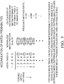
- Fig. 5 illustrates a non-limiting example of a key step in calculating the raw-probability 46 for each vision/radar pair, e.g. for vision-track Vi and radar-glob Rj.
- the way this matching algorithm works is to identify a list of acceptable potential match patterns, give each of them a normalized-value 44, then add up all of the normalized-values 44 for match patterns which match up vision-track Vi and radar-glob Rj.
- V1 is matched to radar-glob ID 2 (R2) in every single match pattern on the list.
- R2 radar-glob ID 2
- the raw-probability 46 for this pair will sum to 1.0. This probability value matches one's intuition based on the observation that this pair was matched in every feasible pattern. In cases where this pair is matched in only a fraction of the patterns, the raw-probability 46 will be between 0.0 and 1.0, depending on the quality/probability of the patterns in which that match appeared. If the pair is matched in none of the patterns, the raw-probability 46 will be 0.0.
- ⁇ x k -1 represents the reduction in match probabilities
- the term (1 - ⁇ ) u k represents the match probability update using the raw value. In cases where zero feasible match patterns are found, the u k term is effectively equal to zero, and only the probability reduction step takes place.
- a possible value for ⁇ is 0.8.
- a particular radar/vision match pair has a match probability of 0.0 when suddenly that pair looks like a great match, and a raw-probability value of 1.0 is computed. If this raw-probability is maintained for several steps, the (filtered) match probability will take the values 0.0, 0.2, 0.36, 0.49, 0.59, 0.67, ... At some point, this value will exceed a threshold (e.g., 0.6) and the radar/vision matches will be re-organized to execute that match-up. So for this threshold, it takes (at least) 5 steps for the match to be made.
- a threshold e.g., 0.6
- an exception may be allowed under some conditions. If the vision track is currently unmatched and then has a sufficiently high value of the raw-probability 46 to a particular radar glob, then the filtered match probability is allowed to jump to 1.0. This allows for an immediate match to be available for fusion in these unambiguous match cases. If the match is ambiguous for that vision track, then the probabilities must be allowed to drift up or down in accordance with the scheme described above.
- Plan re-organize test (based on match probabilities) .
- the match probabilities are inspected for each vision track.
- the radar glob which this vision track wants is already matched to a different vision track, so that other fused track will need to be split apart before any new matching can take place.
- the vision track under consideration may already be matched to a radar glob, so that fused track will need to be split apart.
- the re-organize test 34 is conceptually straightforward. It first breaks apart all of the fused tracks which contain radar or vision pieces needed in the re-organize test, and then re-assembles the pieces as indicated by the match probabilities.
- This step is a conceptually simple implementation of the planned re-organize test of the radar and vision pieces of fused tracks.
- the planning step has already mapped out which radar/vision fused tracks will need to be broken apart, and which of the pieces will need to be put together.
- the fused track IDs of all of the fused tracks involved in the re-organize test has been predetermined in the planning in a way which minimizes unnecessary ID switching.
- the fused track states of the re-organized fused tracks are adjusted to account for the state values of the new radar and vision pieces.
- the algorithm described herein may also include tests to identify suspiciousness of radar globs, vision/radar pairs with long histories of good matching, suspected disappearing radar tracklets, etc.
- Match probabilities are maintained for each vision track to a small set of potential radar-globs which are feasible matches to that vision-track. These match probabilities are obtained by low-pass filtering the values of the raw-probability 46 for each potential vision/radar match-up.
- the raw-probability 46 for a particular vision/radar pair is obtained by summing the normalized-values 44 of the feasible match patterns which indicate that match-up.
- the list of feasible match patterns is obtained efficiently by pre-gating recorded by a feasibility matrix which indicates which individual vision/radar pairs are sufficiently similar that their match-up could be part of a feasible match pattern.
- Each resulting feasible match pattern is additionally scrutinized by the Occlusion function for sensibility, and the match pattern's quality is measured as a function of the discrepancies between radar and vision track state information in each of the indicated radar/vision matches in the pattern.
- vision/radar match probabilities are compared to thresholds and, if needed, re-organization of some of the existing fused tracks is planned and implemented in order to come into compliance with the dictates of the match probabilities.
- the object tracking system 10 which is generally suitable for use on an automated vehicle (e.g. the host-vehicle 12), includes a camera 14 used to capture an image of the VFOV 16 of the camera 14, and a radar-sensor 18 used to detect a radar-signal reflected from the RFOV 20 of the radar-sensor 18 which overlaps the VFOV 16.
- the overlap is such that the VFOV 16 and the RFOV 20 are the same areas or essentially (e.g. >90%) the same areas, but this is not a requirement.
- the system 10 includes a controller 22 in communication with the camera 14 and the radar-sensor 18 so that the controller 22 receives data or information from the camera 14 and the radar-sensor 18 for detecting the presence of actual-objects 24 in the respective fields-of-view.
- the controller 22 is configured or programmed to perform a number of steps to match instances of an object 54 detected by the camera 14 with instances of grouped-tracklets 56 detected by the radar-sensor 18. While the steps below are characterized in terms of first, second, third, etc., steps, this does not suggest that the steps must be performed in the exact order presented, or that other intervening steps are excluded, or that all of the steps described are absolutely required.
- a first step may be to assign a vision-identification 58 to each instance of a vision-track 26 associated with an instance of an object 54 detected by the controller in the image (i.e. information or signal) from the camera 14.
- Fig. 2 illustrates a non-limiting example of a traffic scenario that the system 10 may encounter where the vision-identification 58 is assigned based on the detection of the actual-objects 24 and are indicated as V1, V2, V3, V4, and V5.
- a second step may be to assign a radar-identification 60 to each instance of a radar-glob 28 associated with an instance of grouped-tracklets 56 indicated by the radar-signal detected by the radar-sensor 18.
- Fig. 2 illustrates a non-limiting example where the radar-identification 60 is assigned based on the detection of the actual-objects 24 and are indicated as R1, R2, R3, R4, R5, R6, R7, and R8.
- a third step may be to determine a match-feasibility 36 for each combination of vision-track 26 and radar-glob 28.
- Each match-feasibility 36 is a binary-value set equal to zero (0) or one (1) depending on the outcome of a comparison or test of how closely related an instance of a vision-track 26 and a radar-glob 28 are to each other.
- the match-feasibility 36 of a particular combination of vision-track 26 and radar-glob 28 is set to one (1) when at least one of a) an azimuth-difference 62 between a vision-angle 64 ( Fig.
- a distance-difference 70 between a vision-distance of the vision-track 26 and a radar-distance of a radar-glob 28 is less than a distance-threshold 72, e.g. five meters (5m) or twenty percent (20%) whichever is greater; and c) a speed-difference 74 between a vision-speed 76 of the vision-track 26 and a radar-speed 78 of a radar-glob 28 is less than a speed-threshold 80, e.g.
- , distance-difference
- , and speed-difference
- the vision-speed 76 and the radar-speed 78 may be indicative of a longitudinal-velocity of the vision-track 26 and the radar-glob 28, respectively. That is, only the portion of the vision-speed 76 and the radar-speed 78 that is parallel to the present travel-direction of the host-vehicle 12 may be considered, and any relative lateral movement may be ignored.
- the vision-distance (not shown) and the radar-distance (not shown) may be indicative of a longitudinal-position of the vision-track and the radar-glob, respectively. That is, only the distance parallel to the present travel-direction of the host-vehicle 12 may be considered, and any lateral offset may be ignored.
- the match-feasibility 36 for a particular combination of vision-track 26 and radar-glob 28 may be set equal to zero (0) when the azimuth-difference 62 is not less than the azimuth-threshold 68 regardless of the values of the distance-difference 70 and the speed-difference 74.
- each match-feasibility is set equal to one (1) only when all of the tests are passed, e.g.
- the azimuth-difference 62 is less than the azimuth-threshold 68
- the distance-difference 70 is less than the distance-threshold 72
- the speed-difference 74 between is less than the speed-threshold 80.
- each match-feasibility is set equal to one (1) when at least one of a) the azimuth-difference is less than the azimuth-threshold, b) the distance-difference is less than the distance-threshold, c) the speed-difference between is less than the speed-threshold, and d) a vision-motion-status (not shown) of the vision-track 26 matches a radar-motion-status (not shown) of the radar glob 28, where the vision-motion-status and the radar-motion-status are each characterized by one of oncoming, stationary, and receding which indicate the direction of over-the-ground motion relative to the host-vehicle 12.
- over-the-ground motion not motion relative to the host-vehicle's motion
- over-the-ground motion is key. For example, assume there is another car in front of the host-vehicle 12 which is moving in the same direction but at a reduced speed. The relative motion of that other vehicle is towards the host-vehicle, but it is not characterized as oncoming. Since its over-the-ground motion is in the same direction as the host-vehicle is moving, it is characterized as receding.
- a fourth step may be to select from all possible vision-track and radar-glob pairing-combinations a list of feasible-match-patterns 40.
- a pairing-combination is characterized as a feasible-match-pattern when the match-feasibility 36 of each combination of vision-track 26 and radar-glob 28 in the pairing-combination is equal to one (1).
- all of the match-feasibilities 36 of a pairing-combination may be multiplied together. If the result is one, then each instance of the match-feasibility is one. However, if the result is zero, then at least one instance of the match-feasibility is zero.
- a fifth step may be to determine a quality-value 42 of each instance of the feasible-match-patterns 40.
- the quality-value 42 may be based on a reciprocal of a weighted-combination of instances of the azimuth-difference 62, the distance-difference 70, and the speed-difference 74 used to determine the match-feasibility 36.
- the weighting of each of the differences may be predetermined values, e.g. an azimuth-weighting 82, a distance-weighting 84, and a speed-weighting 86, which may be predetermined values determined by empirical testing.
- a seventh step may be to calculate a raw-probability 46 for each combination of vision-track 26 and radar-glob 28 by summing the normalized-values 44 of the feasible-match-patterns 40 that indicate a match for that combination of vision-track 26 and radar-glob 28.
- An eighth step may be to determine a match-probability 32 for each combination of vision-track 26 and radar-glob 28 by low-pass filtering 48 of the raw-probability 46 obtained for that combination.
- a ninth step may be to determine a need for re-organize test 34 of the existing associations between vision-tracks 26 and radar-globs 28 by comparing the match-probabilities 32 for combinations of vision-track 26 and radar-glob 28 to an upper-threshold 88 and a lower-threshold 90, and implement a re-organize test 34 of associations between vision-tracks 26 and radar-globs 28 when one of the match-probabilities 32 transitions from less than to greater than the upper-threshold 88 or from greater than to less than the lower-threshold 90.
- An additional step between the fourth step and the fifth step may be to perform an occlusion-test 30 on radar-globs characterized by substantially equal values of azimuth-angle to null the match-probability for any combination of vision-track 26 and radar-glob 28 that the occlusion-test 30 indicates is not possible because the line of site to one is occluded by the other.
- an object tracking system (the system 10), a controller 22 for the system 10 and a method described in terms of steps is provided.
- an improved way to match the vision-tracks 26 detected by the camera 14 to radar-globs 28 detected by the radar-sensor 18 is provided.
- the amount of data processing has been reduced by excluding some of the possible combinations via a gating process that determine the match-feasibility 36 of each possible combination.
Landscapes
- Engineering & Computer Science (AREA)
- Remote Sensing (AREA)
- Radar, Positioning & Navigation (AREA)
- Physics & Mathematics (AREA)
- General Physics & Mathematics (AREA)
- Computer Networks & Wireless Communication (AREA)
- Theoretical Computer Science (AREA)
- Multimedia (AREA)
- Electromagnetism (AREA)
- Data Mining & Analysis (AREA)
- Bioinformatics & Computational Biology (AREA)
- General Engineering & Computer Science (AREA)
- Evolutionary Computation (AREA)
- Evolutionary Biology (AREA)
- Computer Vision & Pattern Recognition (AREA)
- Bioinformatics & Cheminformatics (AREA)
- Artificial Intelligence (AREA)
- Life Sciences & Earth Sciences (AREA)
- Signal Processing (AREA)
- Radar Systems Or Details Thereof (AREA)
- Mechanical Engineering (AREA)
- Closed-Circuit Television Systems (AREA)
- Image Analysis (AREA)
Applications Claiming Priority (1)
| Application Number | Priority Date | Filing Date | Title |
|---|---|---|---|
| US15/000,730 US10565468B2 (en) | 2016-01-19 | 2016-01-19 | Object tracking system with radar/vision fusion for automated vehicles |
Publications (2)
| Publication Number | Publication Date |
|---|---|
| EP3196668A1 true EP3196668A1 (fr) | 2017-07-26 |
| EP3196668B1 EP3196668B1 (fr) | 2019-08-14 |
Family
ID=57714549
Family Applications (1)
| Application Number | Title | Priority Date | Filing Date |
|---|---|---|---|
| EP17150307.1A Active EP3196668B1 (fr) | 2016-01-19 | 2017-01-04 | Système de suivi d'objet avec fusion radar/vision destiné à des véhicules automatisés |
Country Status (3)
| Country | Link |
|---|---|
| US (1) | US10565468B2 (fr) |
| EP (1) | EP3196668B1 (fr) |
| CN (1) | CN107238834B (fr) |
Cited By (3)
| Publication number | Priority date | Publication date | Assignee | Title |
|---|---|---|---|---|
| WO2020070563A1 (fr) * | 2018-10-01 | 2020-04-09 | Kpit Technologies Limited | Système de fusion basé sur des capteurs de perception pour la commande d'un véhicule et procédé associé |
| EP3961255A1 (fr) | 2020-08-28 | 2022-03-02 | Aptiv Technologies Limited | Système d'aide au conducteur pour un véhicule, véhicule et procédé d'aide au conducteur pouvant être mis en uvre par le système |
| EP4134700A1 (fr) * | 2021-08-13 | 2023-02-15 | Aptiv Technologies Limited | Contraintes d'occlusion pour la résolution de pistes provenant de plusieurs types de capteurs |
Families Citing this family (56)
| Publication number | Priority date | Publication date | Assignee | Title |
|---|---|---|---|---|
| US10317522B2 (en) * | 2016-03-01 | 2019-06-11 | GM Global Technology Operations LLC | Detecting long objects by sensor fusion |
| JP6547785B2 (ja) * | 2016-07-29 | 2019-07-24 | 株式会社デンソー | 物標検出装置 |
| EP3415945B1 (fr) | 2017-06-12 | 2024-01-10 | Aptiv Technologies Limited | Procédé de détermination du taux de lacet d'un véhicule cible |
| DE112017008095T5 (de) * | 2017-11-13 | 2020-07-16 | Mitsubishi Electric Corporation | Objekterkennungsvorrichtung und Objekterkennungsverfahren |
| US10466346B2 (en) * | 2017-11-17 | 2019-11-05 | Gm Global Technology Operations, Llc | Method and apparatus for continuous tracking in a multi-radar system |
| CN109960254B (zh) * | 2017-12-25 | 2022-09-23 | 深圳市优必选科技有限公司 | 机器人及其路径规划方法 |
| IL258347B (en) * | 2017-12-31 | 2020-11-30 | Elta Systems Ltd | A system and method for combining data from JMT radar and electro-optical sensors |
| EP3525000B1 (fr) * | 2018-02-09 | 2021-07-21 | Bayerische Motoren Werke Aktiengesellschaft | Procédés et appareils de détection d'objets dans une scène sur la base de données lidar et de données radar de la scène |
| KR102391205B1 (ko) * | 2018-03-20 | 2022-04-27 | 주식회사 에이치엘클레무브 | 객체 검출 기반 거리 추정 장치 및 그 방법 |
| EP3546978B1 (fr) * | 2018-03-29 | 2021-12-08 | Aptiv Technologies Limited | Procédé permettant de tester un objet cible comme centre de diffusion à point unique |
| WO2019187093A1 (fr) * | 2018-03-30 | 2019-10-03 | 三菱電機株式会社 | Dispositif d'identification d'objets |
| EP3572839A1 (fr) | 2018-05-23 | 2019-11-27 | Aptiv Technologies Limited | Procédé d'estimation d'une amplitude de la vitesse d'une cible mobile dans un plan horizontal et système de détection radar |
| DE102018208205A1 (de) | 2018-05-24 | 2019-11-28 | Ford Global Technologies, Llc | Verfahren zum Kartographieren der Umgebung von Kraftfahrzeugen |
| EP3575827A1 (fr) | 2018-06-01 | 2019-12-04 | Aptiv Technologies Limited | Procédé d'estimation robuste de la vitesse d'une cible au moyen d'un véhicule hôte |
| CN110609274B (zh) * | 2018-06-15 | 2022-07-01 | 杭州海康威视数字技术股份有限公司 | 一种测距方法、装置及系统 |
| CN108921925B (zh) * | 2018-06-27 | 2022-12-09 | 广州视源电子科技股份有限公司 | 基于激光雷达和视觉融合的语义点云生成方法和装置 |
| US11035943B2 (en) * | 2018-07-19 | 2021-06-15 | Aptiv Technologies Limited | Radar based tracking of slow moving objects |
| EP3611541A1 (fr) | 2018-08-16 | 2020-02-19 | Aptiv Technologies Limited | Procédé de détermination d'une estimation d'incertitude d'une vitesse estimée |
| CN109270523B (zh) * | 2018-09-21 | 2020-09-18 | 宝沃汽车(中国)有限公司 | 多传感器数据融合方法和装置,车辆 |
| CN110378178B (zh) * | 2018-09-30 | 2022-01-28 | 毫末智行科技有限公司 | 目标跟踪方法及装置 |
| US10878282B2 (en) * | 2018-10-15 | 2020-12-29 | Tusimple, Inc. | Segmentation processing of image data for LiDAR-based vehicle tracking system and method |
| CN109459750B (zh) * | 2018-10-19 | 2023-05-23 | 吉林大学 | 一种毫米波雷达与深度学习视觉融合的前方多车辆跟踪方法 |
| CN109375211B (zh) * | 2018-12-10 | 2023-03-10 | 西安电子科技大学 | 基于雷达和多光学设备的可移动无人平台目标搜索方法 |
| JP7169873B2 (ja) * | 2018-12-27 | 2022-11-11 | 株式会社デンソー | 運転支援装置 |
| CN111382768B (zh) | 2018-12-29 | 2023-11-14 | 华为技术有限公司 | 多传感器数据融合方法和装置 |
| CN111856445B (zh) * | 2019-04-11 | 2023-07-04 | 杭州海康威视数字技术股份有限公司 | 一种目标检测方法、装置、设备及系统 |
| CN110095770A (zh) * | 2019-04-26 | 2019-08-06 | 东风柳州汽车有限公司 | 车辆周边目标物的检测方法 |
| IT201900006735A1 (it) * | 2019-05-10 | 2020-11-10 | Sacertis S R L | Metodo di indagine di una struttura e procedimento per definire una modalità ottimale d’indagine della struttura stessa |
| KR20200133863A (ko) | 2019-05-20 | 2020-12-01 | 삼성전자주식회사 | 첨단 운전자 지원 장치, 이의 캘리브레이션 방법 및 이의 객체를 검출하는 방법 |
| CN110133637B (zh) * | 2019-06-05 | 2021-06-01 | 中国科学院长春光学精密机械与物理研究所 | 目标定位方法、装置及系统 |
| CN110517483B (zh) * | 2019-08-06 | 2021-05-18 | 新奇点智能科技集团有限公司 | 一种路况信息处理方法及数字轨路侧单元 |
| CN110794405B (zh) * | 2019-10-18 | 2022-06-10 | 北京全路通信信号研究设计院集团有限公司 | 一种基于相机和雷达融合的目标检测方法及系统 |
| CN112904331B (zh) * | 2019-11-19 | 2024-05-07 | 杭州海康威视数字技术股份有限公司 | 移动轨迹的确定方法、装置、设备及存储介质 |
| WO2021109033A1 (fr) * | 2019-12-04 | 2021-06-10 | Huawei Technologies Co., Ltd. | Appareil et procédé de collecte et de marquage automatique de données de mesure dans un scénario de trafic |
| US11774582B2 (en) * | 2020-01-28 | 2023-10-03 | Aptiv Technologies Limited | Imaging and radar fusion for multiple-object tracking |
| US11594144B2 (en) * | 2020-01-31 | 2023-02-28 | Honeywell International Inc. | Collision awareness using cameras mounted on a vehicle |
| CN111402296B (zh) * | 2020-03-12 | 2023-09-01 | 浙江大华技术股份有限公司 | 基于摄像机、雷达的目标跟踪方法及相关装置 |
| CN111505624B (zh) * | 2020-04-30 | 2022-07-01 | 中国汽车工程研究院股份有限公司 | 一种基于机器视觉和毫米波雷达数据融合的环境感知方法 |
| KR20210152741A (ko) | 2020-06-09 | 2021-12-16 | 삼성전자주식회사 | 첨단 운전자 지원 장치 및 이의 객체를 검출하는 방법 |
| US20220026557A1 (en) * | 2020-07-22 | 2022-01-27 | Plato Systems, Inc. | Spatial sensor system with background scene subtraction |
| CN112285700B (zh) * | 2020-08-24 | 2023-12-15 | 江苏大学 | 基于激光雷达与毫米波雷达融合的机动目标跟踪方法 |
| CN112130136B (zh) * | 2020-09-11 | 2024-04-12 | 中国重汽集团济南动力有限公司 | 一种交通目标综合感知系统及方法 |
| CN116324506A (zh) * | 2020-09-24 | 2023-06-23 | 三菱电机株式会社 | 信息处理系统、信息处理装置、程序和信息处理方法 |
| US11618480B2 (en) | 2020-11-18 | 2023-04-04 | Aptiv Technologies Limited | Kurtosis based pruning for sensor-fusion systems |
| CN112562009A (zh) * | 2020-12-03 | 2021-03-26 | 深圳宇磐科技有限公司 | 一种相机设备参数和安装姿态参数自动标定方法及系统 |
| WO2022122500A1 (fr) * | 2020-12-09 | 2022-06-16 | Symeo Gmbh | Procédé, appareil et système radar de poursuite d'objets |
| DE102021105659A1 (de) | 2020-12-09 | 2022-06-09 | Symeo Gmbh | Verfahren, Vorrichtung und Radarsystem zum Verfolgen von Objekten |
| CN112731371B (zh) * | 2020-12-18 | 2024-01-23 | 重庆邮电大学 | 一种激光雷达与视觉融合的集成化目标跟踪系统及方法 |
| US20220262129A1 (en) | 2021-02-15 | 2022-08-18 | Aptiv Technologies Limited | Multiple Hypothesis-Based Fusion of Sensor Data |
| CN113505732A (zh) * | 2021-07-26 | 2021-10-15 | 浙江大华技术股份有限公司 | 视觉目标的确定方法及装置、存储介质、电子装置 |
| CN113740843B (zh) * | 2021-09-07 | 2024-05-07 | 中国兵器装备集团自动化研究所有限公司 | 一种跟踪目标的运动状态估计方法、系统及电子装置 |
| US20230147100A1 (en) * | 2021-11-11 | 2023-05-11 | Aptiv Technologies Limited | Clustering Track Pairs for Multi-Sensor Track Association |
| CN114998886B (zh) * | 2022-08-04 | 2022-10-28 | 智慧互通科技股份有限公司 | 基于雷视融合的车辆追踪方法以及装置 |
| CN115657012B (zh) * | 2022-12-23 | 2023-04-18 | 深圳佑驾创新科技有限公司 | 图像目标与雷达目标的匹配方法、装置、设备及存储介质 |
| CN116630765B (zh) * | 2023-07-24 | 2023-09-26 | 济南卓伦智能交通技术有限公司 | 一种基于多元信息的单车融合感知系统 |
| CN117093872B (zh) * | 2023-10-19 | 2024-01-02 | 四川数字交通科技股份有限公司 | 雷达目标分类模型自训练方法及系统 |
Citations (3)
| Publication number | Priority date | Publication date | Assignee | Title |
|---|---|---|---|---|
| US20030011509A1 (en) * | 2000-12-20 | 2003-01-16 | Kanako Honda | Method for detecting stationary object on road |
| US20060139204A1 (en) * | 2003-09-11 | 2006-06-29 | Kyoichi Abe | Object detection system and method of detecting object |
| US20130236047A1 (en) * | 2012-03-07 | 2013-09-12 | GM Global Technology Operations LLC | Enhanced data association of fusion using weighted bayesian filtering |
Family Cites Families (14)
| Publication number | Priority date | Publication date | Assignee | Title |
|---|---|---|---|---|
| US6989754B2 (en) * | 2003-06-02 | 2006-01-24 | Delphi Technologies, Inc. | Target awareness determination system and method |
| US7706978B2 (en) * | 2005-09-02 | 2010-04-27 | Delphi Technologies, Inc. | Method for estimating unknown parameters for a vehicle object detection system |
| US7460951B2 (en) * | 2005-09-26 | 2008-12-02 | Gm Global Technology Operations, Inc. | System and method of target tracking using sensor fusion |
| US8812226B2 (en) * | 2009-01-26 | 2014-08-19 | GM Global Technology Operations LLC | Multiobject fusion module for collision preparation system |
| US8232872B2 (en) * | 2009-12-03 | 2012-07-31 | GM Global Technology Operations LLC | Cross traffic collision alert system |
| CN101739843B (zh) * | 2009-12-04 | 2012-08-29 | 河海大学常州校区 | 多视觉信息融合的车辆安全驾驶实时立体感知装置及方法 |
| US20110190972A1 (en) * | 2010-02-02 | 2011-08-04 | Gm Global Technology Operations, Inc. | Grid unlock |
| CN202163431U (zh) * | 2011-06-30 | 2012-03-14 | 中国汽车技术研究中心 | 基于多传感器信息融合的碰撞及偏离预警装置 |
| CN102508246B (zh) * | 2011-10-13 | 2013-04-17 | 吉林大学 | 车辆前方障碍物检测跟踪方法 |
| JP5673568B2 (ja) * | 2012-01-16 | 2015-02-18 | トヨタ自動車株式会社 | 物体検出装置 |
| US9128185B2 (en) * | 2012-03-15 | 2015-09-08 | GM Global Technology Operations LLC | Methods and apparatus of fusing radar/camera object data and LiDAR scan points |
| US9304042B2 (en) * | 2013-01-18 | 2016-04-05 | Delphi Technologies, Inc. | Foreign object detection system and method suitable for source resonator of wireless energy transfer system |
| US9599706B2 (en) * | 2015-04-06 | 2017-03-21 | GM Global Technology Operations LLC | Fusion method for cross traffic application using radars and camera |
| WO2016176487A1 (fr) * | 2015-04-28 | 2016-11-03 | Henri Johnson | Systèmes pour suivre un objet de sport en mouvement |
-
2016
- 2016-01-19 US US15/000,730 patent/US10565468B2/en active Active
-
2017
- 2017-01-04 EP EP17150307.1A patent/EP3196668B1/fr active Active
- 2017-01-19 CN CN201710286682.0A patent/CN107238834B/zh active Active
Patent Citations (3)
| Publication number | Priority date | Publication date | Assignee | Title |
|---|---|---|---|---|
| US20030011509A1 (en) * | 2000-12-20 | 2003-01-16 | Kanako Honda | Method for detecting stationary object on road |
| US20060139204A1 (en) * | 2003-09-11 | 2006-06-29 | Kyoichi Abe | Object detection system and method of detecting object |
| US20130236047A1 (en) * | 2012-03-07 | 2013-09-12 | GM Global Technology Operations LLC | Enhanced data association of fusion using weighted bayesian filtering |
Cited By (3)
| Publication number | Priority date | Publication date | Assignee | Title |
|---|---|---|---|---|
| WO2020070563A1 (fr) * | 2018-10-01 | 2020-04-09 | Kpit Technologies Limited | Système de fusion basé sur des capteurs de perception pour la commande d'un véhicule et procédé associé |
| EP3961255A1 (fr) | 2020-08-28 | 2022-03-02 | Aptiv Technologies Limited | Système d'aide au conducteur pour un véhicule, véhicule et procédé d'aide au conducteur pouvant être mis en uvre par le système |
| EP4134700A1 (fr) * | 2021-08-13 | 2023-02-15 | Aptiv Technologies Limited | Contraintes d'occlusion pour la résolution de pistes provenant de plusieurs types de capteurs |
Also Published As
| Publication number | Publication date |
|---|---|
| US20170206436A1 (en) | 2017-07-20 |
| US10565468B2 (en) | 2020-02-18 |
| CN107238834A (zh) | 2017-10-10 |
| CN107238834B (zh) | 2021-10-08 |
| EP3196668B1 (fr) | 2019-08-14 |
Similar Documents
| Publication | Publication Date | Title |
|---|---|---|
| EP3196668B1 (fr) | Système de suivi d'objet avec fusion radar/vision destiné à des véhicules automatisés | |
| CN107490794B (zh) | 物体辨识处理装置、物体辨识处理方法及自动驾驶系统 | |
| EP3379289A1 (fr) | Système de détection d'objet de véhicule automatisé comportant une fusion d'image de caméra et de données radar | |
| US8055445B2 (en) | Probabilistic lane assignment method | |
| JP6571545B2 (ja) | 物体検出装置および物体検出方法 | |
| EP3398824B1 (fr) | Système de freinage automatique et procede de fonctionnement d'un système de freinage automatique | |
| KR101752858B1 (ko) | 레이더 기반 고 정밀 돌발상황 검지 시스템 | |
| US20140293052A1 (en) | Image-based vehicle detection and distance measuring method and apparatus | |
| CN105083342B (zh) | 在铁路交叉道口处的危险空间监视 | |
| KR102045135B1 (ko) | 자동차의 측방 주변 영역 내의 종방향 연장 정지 물체를 분류하는 방법, 운전자 보조 시스템 및 자동차 | |
| US9812008B2 (en) | Vehicle detection and tracking based on wheels using radar and vision | |
| US9978269B2 (en) | Site-specific traffic analysis including identification of a traffic path | |
| CN109766867B (zh) | 车辆运行状态确定方法、装置、计算机设备和存储介质 | |
| CN113492851A (zh) | 车辆控制装置、车辆控制方法以及车辆控制用计算机程序 | |
| CN114170274B (zh) | 目标跟踪方法和装置、电子设备和存储介质 | |
| CN109421718A (zh) | 自动化速度控制系统 | |
| CN109696676A (zh) | 一种有效障碍物目标确定方法、装置和车辆 | |
| US10279786B2 (en) | Automatic braking system | |
| CN108974007A (zh) | 确定主动巡航控制的兴趣物体 | |
| CN109343051A (zh) | 一种用于高级辅助驾驶的多传感器数据融合方法 | |
| EP3413081B1 (fr) | Procédé d'enregistrement de la présence d'un objet fixe présentant un mouvement sur une scène surveillée par un détecteur radar | |
| US20220055660A1 (en) | Stationary object detection | |
| CN110723144B (zh) | 车道分配系统 | |
| Matowicki et al. | Analysis of possibility to utilize road marking for the needs of autonomous vehicles | |
| CN117940800A (zh) | 用于解决雷达网络中的角度多义性的方法 |
Legal Events
| Date | Code | Title | Description |
|---|---|---|---|
| PUAI | Public reference made under article 153(3) epc to a published international application that has entered the european phase |
Free format text: ORIGINAL CODE: 0009012 |
|
| STAA | Information on the status of an ep patent application or granted ep patent |
Free format text: STATUS: THE APPLICATION HAS BEEN PUBLISHED |
|
| AK | Designated contracting states |
Kind code of ref document: A1 Designated state(s): AL AT BE BG CH CY CZ DE DK EE ES FI FR GB GR HR HU IE IS IT LI LT LU LV MC MK MT NL NO PL PT RO RS SE SI SK SM TR |
|
| AX | Request for extension of the european patent |
Extension state: BA ME |
|
| STAA | Information on the status of an ep patent application or granted ep patent |
Free format text: STATUS: REQUEST FOR EXAMINATION WAS MADE |
|
| 17P | Request for examination filed |
Effective date: 20180126 |
|
| RBV | Designated contracting states (corrected) |
Designated state(s): AL AT BE BG CH CY CZ DE DK EE ES FI FR GB GR HR HU IE IS IT LI LT LU LV MC MK MT NL NO PL PT RO RS SE SI SK SM TR |
|
| STAA | Information on the status of an ep patent application or granted ep patent |
Free format text: STATUS: EXAMINATION IS IN PROGRESS |
|
| 17Q | First examination report despatched |
Effective date: 20180625 |
|
| RAP1 | Party data changed (applicant data changed or rights of an application transferred) |
Owner name: APTIV TECHNOLOGIES LIMITED |
|
| GRAP | Despatch of communication of intention to grant a patent |
Free format text: ORIGINAL CODE: EPIDOSNIGR1 |
|
| STAA | Information on the status of an ep patent application or granted ep patent |
Free format text: STATUS: GRANT OF PATENT IS INTENDED |
|
| INTG | Intention to grant announced |
Effective date: 20190222 |
|
| GRAS | Grant fee paid |
Free format text: ORIGINAL CODE: EPIDOSNIGR3 |
|
| GRAA | (expected) grant |
Free format text: ORIGINAL CODE: 0009210 |
|
| STAA | Information on the status of an ep patent application or granted ep patent |
Free format text: STATUS: THE PATENT HAS BEEN GRANTED |
|
| AK | Designated contracting states |
Kind code of ref document: B1 Designated state(s): AL AT BE BG CH CY CZ DE DK EE ES FI FR GB GR HR HU IE IS IT LI LT LU LV MC MK MT NL NO PL PT RO RS SE SI SK SM TR |
|
| REG | Reference to a national code |
Ref country code: GB Ref legal event code: FG4D |
|
| REG | Reference to a national code |
Ref country code: CH Ref legal event code: EP Ref country code: AT Ref legal event code: REF Ref document number: 1167684 Country of ref document: AT Kind code of ref document: T Effective date: 20190815 |
|
| REG | Reference to a national code |
Ref country code: IE Ref legal event code: FG4D |
|
| REG | Reference to a national code |
Ref country code: DE Ref legal event code: R096 Ref document number: 602017005994 Country of ref document: DE |
|
| REG | Reference to a national code |
Ref country code: NL Ref legal event code: MP Effective date: 20190814 |
|
| REG | Reference to a national code |
Ref country code: LT Ref legal event code: MG4D |
|
| PG25 | Lapsed in a contracting state [announced via postgrant information from national office to epo] |
Ref country code: PT Free format text: LAPSE BECAUSE OF FAILURE TO SUBMIT A TRANSLATION OF THE DESCRIPTION OR TO PAY THE FEE WITHIN THE PRESCRIBED TIME-LIMIT Effective date: 20191216 Ref country code: NO Free format text: LAPSE BECAUSE OF FAILURE TO SUBMIT A TRANSLATION OF THE DESCRIPTION OR TO PAY THE FEE WITHIN THE PRESCRIBED TIME-LIMIT Effective date: 20191114 Ref country code: SE Free format text: LAPSE BECAUSE OF FAILURE TO SUBMIT A TRANSLATION OF THE DESCRIPTION OR TO PAY THE FEE WITHIN THE PRESCRIBED TIME-LIMIT Effective date: 20190814 Ref country code: FI Free format text: LAPSE BECAUSE OF FAILURE TO SUBMIT A TRANSLATION OF THE DESCRIPTION OR TO PAY THE FEE WITHIN THE PRESCRIBED TIME-LIMIT Effective date: 20190814 Ref country code: LT Free format text: LAPSE BECAUSE OF FAILURE TO SUBMIT A TRANSLATION OF THE DESCRIPTION OR TO PAY THE FEE WITHIN THE PRESCRIBED TIME-LIMIT Effective date: 20190814 Ref country code: HR Free format text: LAPSE BECAUSE OF FAILURE TO SUBMIT A TRANSLATION OF THE DESCRIPTION OR TO PAY THE FEE WITHIN THE PRESCRIBED TIME-LIMIT Effective date: 20190814 Ref country code: BG Free format text: LAPSE BECAUSE OF FAILURE TO SUBMIT A TRANSLATION OF THE DESCRIPTION OR TO PAY THE FEE WITHIN THE PRESCRIBED TIME-LIMIT Effective date: 20191114 Ref country code: NL Free format text: LAPSE BECAUSE OF FAILURE TO SUBMIT A TRANSLATION OF THE DESCRIPTION OR TO PAY THE FEE WITHIN THE PRESCRIBED TIME-LIMIT Effective date: 20190814 |
|
| REG | Reference to a national code |
Ref country code: AT Ref legal event code: MK05 Ref document number: 1167684 Country of ref document: AT Kind code of ref document: T Effective date: 20190814 |
|
| PG25 | Lapsed in a contracting state [announced via postgrant information from national office to epo] |
Ref country code: AL Free format text: LAPSE BECAUSE OF FAILURE TO SUBMIT A TRANSLATION OF THE DESCRIPTION OR TO PAY THE FEE WITHIN THE PRESCRIBED TIME-LIMIT Effective date: 20190814 Ref country code: ES Free format text: LAPSE BECAUSE OF FAILURE TO SUBMIT A TRANSLATION OF THE DESCRIPTION OR TO PAY THE FEE WITHIN THE PRESCRIBED TIME-LIMIT Effective date: 20190814 Ref country code: LV Free format text: LAPSE BECAUSE OF FAILURE TO SUBMIT A TRANSLATION OF THE DESCRIPTION OR TO PAY THE FEE WITHIN THE PRESCRIBED TIME-LIMIT Effective date: 20190814 Ref country code: RS Free format text: LAPSE BECAUSE OF FAILURE TO SUBMIT A TRANSLATION OF THE DESCRIPTION OR TO PAY THE FEE WITHIN THE PRESCRIBED TIME-LIMIT Effective date: 20190814 Ref country code: GR Free format text: LAPSE BECAUSE OF FAILURE TO SUBMIT A TRANSLATION OF THE DESCRIPTION OR TO PAY THE FEE WITHIN THE PRESCRIBED TIME-LIMIT Effective date: 20191115 Ref country code: IS Free format text: LAPSE BECAUSE OF FAILURE TO SUBMIT A TRANSLATION OF THE DESCRIPTION OR TO PAY THE FEE WITHIN THE PRESCRIBED TIME-LIMIT Effective date: 20191214 |
|
| PG25 | Lapsed in a contracting state [announced via postgrant information from national office to epo] |
Ref country code: TR Free format text: LAPSE BECAUSE OF FAILURE TO SUBMIT A TRANSLATION OF THE DESCRIPTION OR TO PAY THE FEE WITHIN THE PRESCRIBED TIME-LIMIT Effective date: 20190814 |
|
| PG25 | Lapsed in a contracting state [announced via postgrant information from national office to epo] |
Ref country code: RO Free format text: LAPSE BECAUSE OF FAILURE TO SUBMIT A TRANSLATION OF THE DESCRIPTION OR TO PAY THE FEE WITHIN THE PRESCRIBED TIME-LIMIT Effective date: 20190814 Ref country code: PL Free format text: LAPSE BECAUSE OF FAILURE TO SUBMIT A TRANSLATION OF THE DESCRIPTION OR TO PAY THE FEE WITHIN THE PRESCRIBED TIME-LIMIT Effective date: 20190814 Ref country code: EE Free format text: LAPSE BECAUSE OF FAILURE TO SUBMIT A TRANSLATION OF THE DESCRIPTION OR TO PAY THE FEE WITHIN THE PRESCRIBED TIME-LIMIT Effective date: 20190814 Ref country code: AT Free format text: LAPSE BECAUSE OF FAILURE TO SUBMIT A TRANSLATION OF THE DESCRIPTION OR TO PAY THE FEE WITHIN THE PRESCRIBED TIME-LIMIT Effective date: 20190814 Ref country code: IT Free format text: LAPSE BECAUSE OF FAILURE TO SUBMIT A TRANSLATION OF THE DESCRIPTION OR TO PAY THE FEE WITHIN THE PRESCRIBED TIME-LIMIT Effective date: 20190814 Ref country code: DK Free format text: LAPSE BECAUSE OF FAILURE TO SUBMIT A TRANSLATION OF THE DESCRIPTION OR TO PAY THE FEE WITHIN THE PRESCRIBED TIME-LIMIT Effective date: 20190814 |
|
| PG25 | Lapsed in a contracting state [announced via postgrant information from national office to epo] |
Ref country code: CZ Free format text: LAPSE BECAUSE OF FAILURE TO SUBMIT A TRANSLATION OF THE DESCRIPTION OR TO PAY THE FEE WITHIN THE PRESCRIBED TIME-LIMIT Effective date: 20190814 Ref country code: IS Free format text: LAPSE BECAUSE OF FAILURE TO SUBMIT A TRANSLATION OF THE DESCRIPTION OR TO PAY THE FEE WITHIN THE PRESCRIBED TIME-LIMIT Effective date: 20200224 Ref country code: SM Free format text: LAPSE BECAUSE OF FAILURE TO SUBMIT A TRANSLATION OF THE DESCRIPTION OR TO PAY THE FEE WITHIN THE PRESCRIBED TIME-LIMIT Effective date: 20190814 Ref country code: SK Free format text: LAPSE BECAUSE OF FAILURE TO SUBMIT A TRANSLATION OF THE DESCRIPTION OR TO PAY THE FEE WITHIN THE PRESCRIBED TIME-LIMIT Effective date: 20190814 |
|
| REG | Reference to a national code |
Ref country code: DE Ref legal event code: R097 Ref document number: 602017005994 Country of ref document: DE |
|
| PLBE | No opposition filed within time limit |
Free format text: ORIGINAL CODE: 0009261 |
|
| STAA | Information on the status of an ep patent application or granted ep patent |
Free format text: STATUS: NO OPPOSITION FILED WITHIN TIME LIMIT |
|
| PG2D | Information on lapse in contracting state deleted |
Ref country code: IS |
|
| 26N | No opposition filed |
Effective date: 20200603 |
|
| PG25 | Lapsed in a contracting state [announced via postgrant information from national office to epo] |
Ref country code: MC Free format text: LAPSE BECAUSE OF FAILURE TO SUBMIT A TRANSLATION OF THE DESCRIPTION OR TO PAY THE FEE WITHIN THE PRESCRIBED TIME-LIMIT Effective date: 20190814 Ref country code: SI Free format text: LAPSE BECAUSE OF FAILURE TO SUBMIT A TRANSLATION OF THE DESCRIPTION OR TO PAY THE FEE WITHIN THE PRESCRIBED TIME-LIMIT Effective date: 20190814 |
|
| REG | Reference to a national code |
Ref country code: CH Ref legal event code: PL |
|
| REG | Reference to a national code |
Ref country code: BE Ref legal event code: MM Effective date: 20200131 |
|
| PG25 | Lapsed in a contracting state [announced via postgrant information from national office to epo] |
Ref country code: LU Free format text: LAPSE BECAUSE OF NON-PAYMENT OF DUE FEES Effective date: 20200104 |
|
| PG25 | Lapsed in a contracting state [announced via postgrant information from national office to epo] |
Ref country code: BE Free format text: LAPSE BECAUSE OF NON-PAYMENT OF DUE FEES Effective date: 20200131 Ref country code: CH Free format text: LAPSE BECAUSE OF NON-PAYMENT OF DUE FEES Effective date: 20200131 Ref country code: LI Free format text: LAPSE BECAUSE OF NON-PAYMENT OF DUE FEES Effective date: 20200131 |
|
| PG25 | Lapsed in a contracting state [announced via postgrant information from national office to epo] |
Ref country code: IE Free format text: LAPSE BECAUSE OF NON-PAYMENT OF DUE FEES Effective date: 20200104 |
|
| PG25 | Lapsed in a contracting state [announced via postgrant information from national office to epo] |
Ref country code: MT Free format text: LAPSE BECAUSE OF FAILURE TO SUBMIT A TRANSLATION OF THE DESCRIPTION OR TO PAY THE FEE WITHIN THE PRESCRIBED TIME-LIMIT Effective date: 20190814 Ref country code: CY Free format text: LAPSE BECAUSE OF FAILURE TO SUBMIT A TRANSLATION OF THE DESCRIPTION OR TO PAY THE FEE WITHIN THE PRESCRIBED TIME-LIMIT Effective date: 20190814 |
|
| PG25 | Lapsed in a contracting state [announced via postgrant information from national office to epo] |
Ref country code: MK Free format text: LAPSE BECAUSE OF FAILURE TO SUBMIT A TRANSLATION OF THE DESCRIPTION OR TO PAY THE FEE WITHIN THE PRESCRIBED TIME-LIMIT Effective date: 20190814 |
|
| PGFP | Annual fee paid to national office [announced via postgrant information from national office to epo] |
Ref country code: FR Payment date: 20230123 Year of fee payment: 7 |
|
| P01 | Opt-out of the competence of the unified patent court (upc) registered |
Effective date: 20230424 |
|
| PGFP | Annual fee paid to national office [announced via postgrant information from national office to epo] |
Ref country code: DE Payment date: 20240110 Year of fee payment: 8 Ref country code: GB Payment date: 20240129 Year of fee payment: 8 |