EP3196446B1 - Verfahren zum betreiben einer brennkraftmaschine und brennkraftmaschine - Google Patents
Verfahren zum betreiben einer brennkraftmaschine und brennkraftmaschine Download PDFInfo
- Publication number
- EP3196446B1 EP3196446B1 EP16204200.6A EP16204200A EP3196446B1 EP 3196446 B1 EP3196446 B1 EP 3196446B1 EP 16204200 A EP16204200 A EP 16204200A EP 3196446 B1 EP3196446 B1 EP 3196446B1
- Authority
- EP
- European Patent Office
- Prior art keywords
- combustion engine
- gas
- combustion chamber
- valve
- operating
- Prior art date
- Legal status (The legal status is an assumption and is not a legal conclusion. Google has not performed a legal analysis and makes no representation as to the accuracy of the status listed.)
- Active
Links
Images


Classifications
-
- F—MECHANICAL ENGINEERING; LIGHTING; HEATING; WEAPONS; BLASTING
- F02—COMBUSTION ENGINES; HOT-GAS OR COMBUSTION-PRODUCT ENGINE PLANTS
- F02D—CONTROLLING COMBUSTION ENGINES
- F02D41/00—Electrical control of supply of combustible mixture or its constituents
- F02D41/0002—Controlling intake air
-
- F—MECHANICAL ENGINEERING; LIGHTING; HEATING; WEAPONS; BLASTING
- F02—COMBUSTION ENGINES; HOT-GAS OR COMBUSTION-PRODUCT ENGINE PLANTS
- F02B—INTERNAL-COMBUSTION PISTON ENGINES; COMBUSTION ENGINES IN GENERAL
- F02B43/00—Engines characterised by operating on gaseous fuels; Plants including such engines
-
- F—MECHANICAL ENGINEERING; LIGHTING; HEATING; WEAPONS; BLASTING
- F01—MACHINES OR ENGINES IN GENERAL; ENGINE PLANTS IN GENERAL; STEAM ENGINES
- F01L—CYCLICALLY OPERATING VALVES FOR MACHINES OR ENGINES
- F01L1/00—Valve-gear or valve arrangements, e.g. lift-valve gear
- F01L1/34—Valve-gear or valve arrangements, e.g. lift-valve gear characterised by the provision of means for changing the timing of the valves without changing the duration of opening and without affecting the magnitude of the valve lift
- F01L1/344—Valve-gear or valve arrangements, e.g. lift-valve gear characterised by the provision of means for changing the timing of the valves without changing the duration of opening and without affecting the magnitude of the valve lift changing the angular relationship between crankshaft and camshaft, e.g. using helicoidal gear
-
- F—MECHANICAL ENGINEERING; LIGHTING; HEATING; WEAPONS; BLASTING
- F02—COMBUSTION ENGINES; HOT-GAS OR COMBUSTION-PRODUCT ENGINE PLANTS
- F02B—INTERNAL-COMBUSTION PISTON ENGINES; COMBUSTION ENGINES IN GENERAL
- F02B1/00—Engines characterised by fuel-air mixture compression
- F02B1/02—Engines characterised by fuel-air mixture compression with positive ignition
- F02B1/04—Engines characterised by fuel-air mixture compression with positive ignition with fuel-air mixture admission into cylinder
- F02B1/06—Methods of operating
-
- F—MECHANICAL ENGINEERING; LIGHTING; HEATING; WEAPONS; BLASTING
- F02—COMBUSTION ENGINES; HOT-GAS OR COMBUSTION-PRODUCT ENGINE PLANTS
- F02B—INTERNAL-COMBUSTION PISTON ENGINES; COMBUSTION ENGINES IN GENERAL
- F02B37/00—Engines characterised by provision of pumps driven at least for part of the time by exhaust
-
- F—MECHANICAL ENGINEERING; LIGHTING; HEATING; WEAPONS; BLASTING
- F02—COMBUSTION ENGINES; HOT-GAS OR COMBUSTION-PRODUCT ENGINE PLANTS
- F02D—CONTROLLING COMBUSTION ENGINES
- F02D13/00—Controlling the engine output power by varying inlet or exhaust valve operating characteristics, e.g. timing
- F02D13/02—Controlling the engine output power by varying inlet or exhaust valve operating characteristics, e.g. timing during engine operation
- F02D13/0203—Variable control of intake and exhaust valves
- F02D13/0215—Variable control of intake and exhaust valves changing the valve timing only
- F02D13/0219—Variable control of intake and exhaust valves changing the valve timing only by shifting the phase, i.e. the opening periods of the valves are constant
-
- F—MECHANICAL ENGINEERING; LIGHTING; HEATING; WEAPONS; BLASTING
- F02—COMBUSTION ENGINES; HOT-GAS OR COMBUSTION-PRODUCT ENGINE PLANTS
- F02D—CONTROLLING COMBUSTION ENGINES
- F02D13/00—Controlling the engine output power by varying inlet or exhaust valve operating characteristics, e.g. timing
- F02D13/02—Controlling the engine output power by varying inlet or exhaust valve operating characteristics, e.g. timing during engine operation
- F02D13/0261—Controlling the valve overlap
-
- F—MECHANICAL ENGINEERING; LIGHTING; HEATING; WEAPONS; BLASTING
- F02—COMBUSTION ENGINES; HOT-GAS OR COMBUSTION-PRODUCT ENGINE PLANTS
- F02D—CONTROLLING COMBUSTION ENGINES
- F02D19/00—Controlling engines characterised by their use of non-liquid fuels, pluralities of fuels, or non-fuel substances added to the combustible mixtures
- F02D19/02—Controlling engines characterised by their use of non-liquid fuels, pluralities of fuels, or non-fuel substances added to the combustible mixtures peculiar to engines working with gaseous fuels
- F02D19/021—Control of components of the fuel supply system
- F02D19/023—Control of components of the fuel supply system to adjust the fuel mass or volume flow
- F02D19/024—Control of components of the fuel supply system to adjust the fuel mass or volume flow by controlling fuel injectors
-
- F—MECHANICAL ENGINEERING; LIGHTING; HEATING; WEAPONS; BLASTING
- F02—COMBUSTION ENGINES; HOT-GAS OR COMBUSTION-PRODUCT ENGINE PLANTS
- F02D—CONTROLLING COMBUSTION ENGINES
- F02D41/00—Electrical control of supply of combustible mixture or its constituents
- F02D41/0025—Controlling engines characterised by use of non-liquid fuels, pluralities of fuels, or non-fuel substances added to the combustible mixtures
- F02D41/0027—Controlling engines characterised by use of non-liquid fuels, pluralities of fuels, or non-fuel substances added to the combustible mixtures the fuel being gaseous
-
- F—MECHANICAL ENGINEERING; LIGHTING; HEATING; WEAPONS; BLASTING
- F02—COMBUSTION ENGINES; HOT-GAS OR COMBUSTION-PRODUCT ENGINE PLANTS
- F02M—SUPPLYING COMBUSTION ENGINES IN GENERAL WITH COMBUSTIBLE MIXTURES OR CONSTITUENTS THEREOF
- F02M21/00—Apparatus for supplying engines with non-liquid fuels, e.g. gaseous fuels stored in liquid form
- F02M21/02—Apparatus for supplying engines with non-liquid fuels, e.g. gaseous fuels stored in liquid form for gaseous fuels
- F02M21/0218—Details on the gaseous fuel supply system, e.g. tanks, valves, pipes, pumps, rails, injectors or mixers
- F02M21/0248—Injectors
- F02M21/0275—Injectors for in-cylinder direct injection, e.g. injector combined with spark plug
-
- F—MECHANICAL ENGINEERING; LIGHTING; HEATING; WEAPONS; BLASTING
- F02—COMBUSTION ENGINES; HOT-GAS OR COMBUSTION-PRODUCT ENGINE PLANTS
- F02B—INTERNAL-COMBUSTION PISTON ENGINES; COMBUSTION ENGINES IN GENERAL
- F02B2275/00—Other engines, components or details, not provided for in other groups of this subclass
- F02B2275/32—Miller cycle
-
- F—MECHANICAL ENGINEERING; LIGHTING; HEATING; WEAPONS; BLASTING
- F02—COMBUSTION ENGINES; HOT-GAS OR COMBUSTION-PRODUCT ENGINE PLANTS
- F02D—CONTROLLING COMBUSTION ENGINES
- F02D41/00—Electrical control of supply of combustible mixture or its constituents
- F02D41/0002—Controlling intake air
- F02D2041/001—Controlling intake air for engines with variable valve actuation
-
- Y—GENERAL TAGGING OF NEW TECHNOLOGICAL DEVELOPMENTS; GENERAL TAGGING OF CROSS-SECTIONAL TECHNOLOGIES SPANNING OVER SEVERAL SECTIONS OF THE IPC; TECHNICAL SUBJECTS COVERED BY FORMER USPC CROSS-REFERENCE ART COLLECTIONS [XRACs] AND DIGESTS
- Y02—TECHNOLOGIES OR APPLICATIONS FOR MITIGATION OR ADAPTATION AGAINST CLIMATE CHANGE
- Y02T—CLIMATE CHANGE MITIGATION TECHNOLOGIES RELATED TO TRANSPORTATION
- Y02T10/00—Road transport of goods or passengers
- Y02T10/10—Internal combustion engine [ICE] based vehicles
- Y02T10/12—Improving ICE efficiencies
-
- Y—GENERAL TAGGING OF NEW TECHNOLOGICAL DEVELOPMENTS; GENERAL TAGGING OF CROSS-SECTIONAL TECHNOLOGIES SPANNING OVER SEVERAL SECTIONS OF THE IPC; TECHNICAL SUBJECTS COVERED BY FORMER USPC CROSS-REFERENCE ART COLLECTIONS [XRACs] AND DIGESTS
- Y02—TECHNOLOGIES OR APPLICATIONS FOR MITIGATION OR ADAPTATION AGAINST CLIMATE CHANGE
- Y02T—CLIMATE CHANGE MITIGATION TECHNOLOGIES RELATED TO TRANSPORTATION
- Y02T10/00—Road transport of goods or passengers
- Y02T10/10—Internal combustion engine [ICE] based vehicles
- Y02T10/30—Use of alternative fuels, e.g. biofuels
-
- Y—GENERAL TAGGING OF NEW TECHNOLOGICAL DEVELOPMENTS; GENERAL TAGGING OF CROSS-SECTIONAL TECHNOLOGIES SPANNING OVER SEVERAL SECTIONS OF THE IPC; TECHNICAL SUBJECTS COVERED BY FORMER USPC CROSS-REFERENCE ART COLLECTIONS [XRACs] AND DIGESTS
- Y02—TECHNOLOGIES OR APPLICATIONS FOR MITIGATION OR ADAPTATION AGAINST CLIMATE CHANGE
- Y02T—CLIMATE CHANGE MITIGATION TECHNOLOGIES RELATED TO TRANSPORTATION
- Y02T10/00—Road transport of goods or passengers
- Y02T10/10—Internal combustion engine [ICE] based vehicles
- Y02T10/40—Engine management systems
Definitions
- the invention relates to a method for operating an internal combustion engine with the features according to the preamble of claim 1. Furthermore, the invention relates to an internal combustion engine according to the preamble of claim 10.
- An advantageous fuel for internal combustion engines is gas, especially natural gas, for example compressed natural gas (CNG), with a high methane content, as it has a high octane number and a high degree of purity.
- natural gas for example compressed natural gas (CNG)
- CONG compressed natural gas
- the injectors are supplied with gas for the internal mixture formation from a gas distribution pipe (gas rail), which is operated at a specific gas pressure and is connected to a gas tank via a pressure reducer.
- the level of the specific gas pressure determines the injection time for the gas into the combustion chamber, which shortens as the gas pressure increases.
- the specific gas pressure should be set relatively low, as it also defines the minimum pressure at which gas still flows from the gas tank into the gas rail. This results in restrictions on the injection times of gas into the combustion chamber.
- the time available (time window) for the introduction of the gas is limited on the one hand by the closing of the outlet valve, so that unburned gas is not flushed out of the combustion chamber.
- the introduction of the gas must be completed before the pressure in the combustion chamber becomes too high during compression. If the pressure in the combustion chamber is higher than the gas pressure, the desired amount of gas cannot enter the combustion chamber due to the resistance or gas may even flow back through the injector.
- the internal combustion engine can be operated bivalently with a first fuel, in particular gas, which is introduced into an intake manifold, and with a second fuel, in particular gasoline, which is injected directly into a combustion chamber.
- a first fuel in particular gas
- a second fuel in particular gasoline
- the duration of the opening of an intake valve of the combustion chamber and the closing time of the intake valve can be varied depending on the torque for different operating modes.
- an internal combustion engine preferably a gasoline engine, with a camshaft is described, which is designed as a direct injection engine and can be operated with compressed natural gas as an alternative to gasoline.
- a cam is adjustable relative to the camshaft so that a valve control time of the gas exchange valve assigned to this cam can be varied.
- the adjustable cam preferably controls an inlet valve and an outlet valve of a cylinder of the internal combustion engine at the same time.
- a bivalent gas-diesel engine in which the crankshaft angle at which the maximum opening of an exhaust valve is located can be varied.
- a phase adjuster or a cam switch is used, for example. It is preferably a two-stroke engine.
- Compression-ignited or spark-ignited internal combustion engines are produced, which can be operated stoichiometrically with gas. Control times and/or opening widths can be changed using a variable valve train.
- the intake valve can be closed before the end of the intake stroke or during the compression stroke.
- the gas is preferably blown directly into the combustion chambers in the compression stroke after the intake valve has closed.
- the object of the present invention is to provide a large time window for the injection of gas directly into the combustion chamber of an internal combustion engine operated with gas.
- the internal combustion engine comprises at least one combustion chamber which has at least one intake valve and at least one exhaust valve, and the at least one intake valve is openable (can be opened) for an intake event for introducing a charge into the combustion chamber for the duration of rotation by a crankshaft angle.
- gas is blown directly into the at least one combustion chamber of the internal combustion engine after the at least one exhaust valve is closed and before the charge in the combustion chamber is compressed with injected gas.
- the at least one intake valve is opened before the at least one exhaust valve is closed for the intake event. At least part of the amount of gas is blown directly into the at least one combustion chamber of the internal combustion engine while the at least one intake valve is open, the internal combustion engine being charged with a compressor.
- an overlap of the opening times of the at least one exhaust valve and the at least one intake valve is brought about (valve overlap).
- This process is also widely referred to as scavenging.
- the residual gas is advantageously flushed out of the combustion chamber (scavenging charge exchange), which results in a higher fresh air charge compared to operation without valve overlap.
- An intake event is a period of time during which the at least one intake valve, in particular at least one of the several intake valves, is open from a point in time at which the at least one intake valve, in particular at least one of the several intake valves, is closed, to a first subsequent point in time at which the at least one intake valve, in particular at least one of the several intake valves, is closed again.
- Each further subsequent opening and closing defines a further intake event.
- inlet event there is preferably exactly one inlet event. Furthermore, there is preferably only one outlet event, for which an analogous definition to the inlet event applies.
- the intake valve is closed before or (preferably) after the combustion chamber has reached a maximum volume, i.e. before the end of an intake stroke or preferably already in the compression stroke.
- a maximum volume i.e. before the end of an intake stroke or preferably already in the compression stroke.
- the internal combustion engine is operated in a Miller cycle. This increases the geometric expansion without increasing the compression pressure.
- crankshaft angle of the intake event is greater than 188 degrees and less than 200 degrees, in particular greater than 190 degrees and less than 198 degrees, preferably greater than 192 degrees and less than 196 degrees.
- the time relating to the cycle of the combustion process is measured in crankshaft angle size, and relative time information is given in crankshaft angle positions.
- the method is used in internal combustion engines with external ignition.
- the compressed charge in the combustion chamber is externally ignited. In this way, the advantageous combustion properties of the gas are utilized.
- the opening of the at least one intake valve in the internal combustion engine is adjustable or adjusted by means of a phase adjuster in its crankshaft angle position.
- the opening of the at least one intake valve can be adjusted from a first point in time, which is after the exhaust valve closes, to a second point in time, which is before the exhaust valve closes, by means of a phase adjuster of an intake camshaft of the internal combustion engine. In this way, the valve overlap can be adjusted, in particular can be switched on and off as required.
- the closing of the at least one exhaust valve in the internal combustion engine is adjustable or is adjusted by means of a phase adjuster in its crankshaft angular position.
- the closing of the at least one exhaust valve is adjusted from a first point in time, which is before the opening of the intake valve, to a second point in time, which is after the opening of the intake valve.
- the valve overlap can also be adjusted, in particular can be switched on and off as required.
- the flushing of the residual gas from the combustion chamber can be supported, preferably further enhanced.
- a mass flow through a throttle device of the internal combustion engine can be increased in the method according to the invention by increasing the opening of the throttle device.
- charge exchange losses can also be reduced thanks to a higher intake manifold pressure.
- the inventive concept also relates to an internal combustion engine that can be operated using gas as fuel.
- the internal combustion engine according to the invention has an engine control unit that includes at least one computer and one memory element.
- a program is stored in the memory element that, when at least partially executed in the computer, carries out the steps of a method with features or combinations of features according to this representation.
- the internal combustion engine can be a traction machine of a vehicle, in particular a trackless land vehicle.
- the internal combustion engine can be superchargeable, in particular the internal combustion engine can have a supercharging group, for example with at least one, preferably exactly one exhaust gas turbocharger.
- the internal combustion engine according to the invention can also have a liquid fuel distribution system, so that the internal combustion engine can be operated bivalently, alternately with a liquid fuel, in particular with gasoline, and with gas.
- the internal combustion engine can also be an internal combustion engine with direct injection of the liquid fuel.
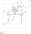
- Figure 1 shows a topology of an embodiment of an internal combustion engine 12, which is operated with gas, in particular natural gas or CNG, as fuel, in a vehicle 10 with an engine control unit 30 and an engine block 14.
- the internal combustion engine 12 is a spark-ignition internal combustion engine in this preferred embodiment.
- the internal combustion engine 12 can be charged by means of an exhaust gas turbocharger 18.
- the air is compressed in the fresh gas system 16 by a compressor 20 of the exhaust gas turbocharger 18. Downstream of the compressor 20 there is a throttle device (not shown in the drawing here).
- Each combustion chamber 26 is assigned a gas injector 28, with which gas can be introduced directly into the combustion chamber.
- the gas is distributed to the gas injectors 28 from a gas tank (not shown in the drawing here) via a gas rail (not shown in the drawing here).
- the gas rail is located downstream of a pressure reducing valve (not shown in the drawing here), which reduces the gas pressure from the tank pressure to the gas rail pressure.
- the exhaust gas discharged from the combustion chambers 26 reaches an exhaust system 22, in which initially drives a turbine 24 of the exhaust gas turbocharger 18.
- the relaxed exhaust gas then flows through exhaust gas aftertreatment components not shown in the drawing here.
- the Figure 2 schematically shows the sequence of a preferred embodiment of the method according to the invention.
- a spark-ignition internal combustion engine 12 with a topology according to the Figure 1 is operated with gas as fuel, with at least one inlet valve and at least one outlet valve of a combustion chamber 26 being opened and closed in cycles and the compressed charge being ignited with injected gas.
- the at least one outlet valve is opened in order to remove the exhaust gas from the combustion chamber mainly during the exhaust stroke.
- the at least one inlet valve is opened for an intake event before the at least one outlet valve is already closed again. In this way, valve overlap is brought about.
- the time window begins in which gas is injected into the combustion chamber (step 40), with the at least one inlet valve still open and the internal combustion engine being charged by means of the compressor.
- the time window then extends in particular into the intake stroke. Gas is no longer injected as soon as the charge is compressed with the injected gas in the combustion chamber 26. This is particularly the case when the at least one intake valve has been closed and at the same time the volume of the combustion chamber is geometrically reduced.
- the at least one intake valve is closed after the combustion chamber 26 has reached a maximum volume and the volume is already decreasing again (Miller cycle). This is followed in step 44 by the compression of the charge, which is then ignited so that a next working cycle begins.
- the Figure 3 shows preferred valve lift profiles of the preferred embodiment according to the invention.
- the height of the valve lift 48 is shown as a function of the crankshaft angle position 46 in degrees (°KW).
- the crankshaft angle is a measure of the relative time in the cycle of the combustion process.
- the crankshaft angles 0 degrees and 360 degrees are the times of the minimum volume of the combustion chamber, the crankshaft angles -180 degrees and 180 degrees are the times of the maximum volume of the combustion chamber. Ignition takes place in the range of 360 degrees crankshaft angle.
- the exhaust valve lift profile 50 extends essentially from -240 degrees to 30 degrees crankshaft angle.
- a reference 52 of the stroke curve for an intake valve is shown.
- This reference 52 represents the typical position of the stroke curve as a function of the crankshaft angle, which, for example, for which gasoline can be used.
- the intake valve lift profile 54 is earlier in the cycle than the reference 52. Since the intake valve lift profile 54 extends essentially from -60 degrees to 210 degrees, a valve overlap is realized in this intake event.
- a time window 56 from crankshaft angle 0 degrees to 270 degrees before ignition at 360 degrees crankshaft angle is available for the reference 52 of the stroke curve for the introduction of the gas into the combustion chamber. If gas is injected with the intake valve open, part of the gas flows through the intake valve towards the fresh gas system, in particular the intake manifold. This creates an operating point that is comparable to external mixture formation.
- the length of the intake event is set to 194 degrees crankshaft angle in the preferred version for reasons of optimal fresh gas filling.
- the injection In order to be able to use the advantage of injection directly into the combustion chamber, especially in the low-end torque range, the injection must be stopped after the intake valve has closed. In the context of reference 52, this is the case in the example shown at 240 degrees crankshaft angle. This means that up to the injection limit of 270 degrees, only 30 degrees crankshaft angle are available to release the entire amount of natural gas due to the increasing cylinder pressure.
- the intake event is moved to an early position, preferably to a maximum early position, using a phase adjuster, whereby a valve overlap with the exhaust valve takes place.
- a phase adjuster for adjusting 60 degrees crankshaft angle, so that 90 degrees crankshaft angle is now available for supplying the gas.
- this operating mode is of particular interest for the low-end torque range in supercharged gas-powered internal combustion engines, since the turbine output is not sufficient to compensate for the filling disadvantage of external mixture formation.
- the start of gas injection can, according to the invention, also take place while the intake valve is open.
- the filling disadvantage that results from this is effectively counteracted by increasing the boost pressure.
- the available time window can be increased even further.
- a time window of 270 degrees crankshaft angle can be achieved.
- the described operation with external mixture formation even has a positive effect on the consumption of the internal combustion engine.
- the filling disadvantage is compensated here by a further opening of the throttle device, for example a throttle valve.
Landscapes
- Engineering & Computer Science (AREA)
- Chemical & Material Sciences (AREA)
- Mechanical Engineering (AREA)
- General Engineering & Computer Science (AREA)
- Combustion & Propulsion (AREA)
- Chemical Kinetics & Catalysis (AREA)
- General Chemical & Material Sciences (AREA)
- Oil, Petroleum & Natural Gas (AREA)
- Output Control And Ontrol Of Special Type Engine (AREA)
Description
- Die Erfindung betrifft ein Verfahren zum Betreiben einer Brennkraftmaschine mit den Merkmalen gemäß dem Oberbegriff des Anspruchs 1. Des Weiteren betrifft die Erfindung eine Brennkraftmaschine gemäß dem Oberbegriff des Anspruchs 10.
- Ein vorteilhafter Kraftstoff für Brennkraftmaschinen ist Gas, insbesondere Erdgas, zum Beispiel Compressed Natural Gas (CNG), mit einem hohen Methananteil, da es eine große Oktanzahl und einen hohen Reinheitsgrad aufweist. Es gibt grundlegend zwei verschiedene Wege, das Gas einer Brennkammer der Brennkraftmaschine zuzuführen: In einer ersten Klasse von Brennkraftmaschinen erfolgt eine Saugrohreinblasung, bevorzugt an einer Mehrzahl von Positionen in zylinderindividuellen Fluidleitungen des Saugrohrs (äußere Gemischbildung). In einer zweiten Klasse von Brennkraftmaschinen wird das Gas direkt in die Brennkammer injiziert (innere Gemischbildung).
- Versorgt werden die Injektoren mit Gas für die innere Gemischbildung aus einem Gasverteilerrohr (Gasrail), welches mit einem bestimmten Gasdruck betrieben wird und über einen Druckminderer mit einem Gastank verbunden ist. Die Höhe des bestimmten Gasdruck bedingt die Injektionszeit für das Gas in die Brennkammer, welche sich mit zunehmendem Gasdruck verkürzt. Aus praktischen Gründen sollte der bestimmte Gasdruck aber eher niedrig festgelegt sein, da er gleichzeitig den minimalen Druck definiert, bei dem noch Gas aus dem Gastank in das Gasrail strömt. In der Folge ergeben sich Restriktionen für die Injektionszeiten von Gas in die Brennkammer hinein. Limitierend für die zur Verfügung stehende Zeitdauer (Zeitfenster) für die Einbringung des Gases ist einerseits das Schließen des Auslassventils, damit unverbranntes Gas nicht aus der Brennkammer gespült wird. Anderseits muss die Einbringung des Gases beendet sein, bevor der Druck in der Brennkammer während der Kompression zu hohe Werte annimmt. Wenn der Druck in der Brennkammer höher als der Gasdruck ist, kann aufgrund des Widerstands nicht die gewünschte Gasmenge in die Brennkammer gelangen oder sogar eine Rückströmung von Gas durch den Injektor erfolgen.
- Damit scheint die einbringbare Gasmenge bei einer Direktinjektion grundlegend beschränkt. Fraglich ist daher, welche Variabilität hinsichtlich dem Einsetzen der Kompression und dem Schließen des Auslassventils besteht.
- Aus dem Dokument
DE 10 2012 001 650 A1 gehen ein Verfahren zum Betreiben einer Brennkraftmaschine sowie eine Brennkraftmaschine hervor. Die Brennkraftmaschine ist bivalent wahlweise mit einem ersten Kraftstoff, der in ein Saugrohr eingebracht wird, insbesondere Gas, und mit einem zweiten Kraftstoff, der direkt in eine Brennkammer eingespritzt wird, insbesondere Benzin, betreibbar. Vor dem Hintergrund, trotz unterschiedlicher Kraftstoffeigenschaften einen niedrigen Verbrauch beim Betrieb der Brennkraftmaschine zu erzielen, können für verschiedene Betriebsarten die Zeitdauer der Öffnungszeiten eines Einlassventils der Brennkammer und der Schließzeitpunkt des Einlassventils in Abhängigkeit des Drehmoments variiert werden. - Zum Beispiel ist im Dokument
DE 10 2006 014 965 A1 eine Brennkraftmaschine, bevorzugt ein Ottomotor, mit einer Nockenwelle beschrieben, der als Direkteinspritzer ausgeführt und alternativ zu Benzin unter anderem auch mit verdichtetem Erdgas betreibbar ist. Ein Nocken ist relativ zur Nockenwelle verstellbar, so dass eine Ventilsteuerzeit des diesem Nocken zugeordneten Gaswechselventils variiert werden kann. Der verstellbare Nocken steuert bevorzugt gleichzeitig ein Einlassventil und ein Auslassventil eines Zylinders der Brennkraftmaschine an. - Aus dem Dokument
US 2015/0252695 A1 ist ein bivalenter Gas-Dieselmotor bekannt, in welchem der Kurbelwellenwinkel, an dem das Öffnungsmaximum eines Auslassventils liegt, variierbar ist. Um die Steuerzeit des Auslassventils zu verändert, gelangt zum Beispiel ein Phasensteller oder ein Nockenumschalter zum Einsatz. Bevorzugt handelt es sich um einen Zweitaktmotor. - Aus den Dokumenten
WO 2012/021990 A1 undCA 2 881 529 A1 gehen kompressionsgezündete oder fremdgezündete Brennkraftmaschinen hervor, welche mit Gas stöchiometrisch betreibbar sind. Mittels eines variablen Ventiltriebs sind Steuerzeiten und/oder Öffnungsweiten veränderbar. Das Einlassventil kann vor dem Ende des Einlasstaktes oder während des Kompressionstaktes geschlossen werden. Das Gas wird bevorzugt im Kompressionstakt nach Schließen des Einlassventils direkt in die Brennkammern eingeblasen. - Im Dokument
DE 10 2013 219 982 A1 wird ein Verfahren zum Betrieb einer fremdgezündeten Viertakt-Brennkraftmaschine mit Gas als Treibstoff beschrieben. In bestimmten Lastsituationen wird die Brennkraftmaschine mit positiver Ventilüberschneidung betrieben. Das Gas wird direkt in die Brennkammern eingeblasen, nachdem das Einlassventil geschlossen wurde. - Vor diesem Hintergrund stellt sich die Frage, inwiefern das Zeitfenster für die Gasinjektion vergrößert werden kann.
- Aufgabe der vorliegenden Erfindung ist es, für eine mit Gas betreibbare Brennkraftmaschine ein großes Zeitfenster für die Injektion von Gas direkt in die Brennkammer zu ermöglichen.
- Diese Aufgabe wird erfindungsgemäß durch ein Verfahren zum Betreiben einer Brennkraftmaschine mit den Merkmalen gemäß Anspruch 1 gelöst. Vorteilhafte Weiterbildungen der Erfindung sind in den abhängigen Ansprüchen charakterisiert.
- Im erfindungsgemäßen Verfahren zum Betreiben einer Brennkraftmaschine umfasst die Brennkraftmaschine wenigstens eine Brennkammer, die wenigstens ein Einlassventil und wenigstens ein Auslassventil aufweist, und ist das wenigstens eine Einlassventil für ein Einlassevent zum Einbringen einer Ladung in die Brennkammer für die Zeitdauer des Drehens um einen Kurbelwellenwinkel öffnenbar (kann geöffnet werden). Erfindungsgemäß wird Gas direkt in die wenigstens eine Brennkammer der Brennkraftmaschine eingeblasen, nachdem das wenigstens eine Auslassventil geschlossen wird und bevor die in der Brennkammer befindliche Ladung mit eingeblasenem Gas verdichtet wird. Dabei wird das wenigstens eine Einlassventil vor Schließen des wenigstens einen Auslassventils für das Einlassevent geöffnet. Dabei wird wenigstens ein Teil der Menge des Gases direkt in die wenigstens eine Brennkammer der Brennkraftmaschine eingeblasen, während das wenigstens eine Einlassventil geöffnet ist, wobei die Brennkraftmaschine mit einem Verdichter aufgeladen wird.
- Mit anderen Worten, im erfindungsgemäßen Verfahren wird eine Überschneidung der Öffnungszeiten des wenigstens einen Auslassventils und des wenigstens einen Einlassventils bewirkt (Ventilüberschneidung). Dieser Vorgang wird auch verbreitet als Scavenging bezeichnet. Auf diese Weise wird vorteilhaft das Restgas aus dem Brennraum ausgespült (spülender Ladungswechsel), wodurch sich eine verglichen zum Betrieb ohne Ventilüberschneidung höhere Frischluftfüllung ergibt.
- Aufgrund des erfindungsgemäßen frühen Öffnens des Einlassventils steht bis zur Verdichtung der in der Brennkammer befindlichen Ladung ein großes Zeitfenster für das Einblasen des Gases zur Verfügung.
- Bei mehreren Auslassventilen können insbesondere alle Auslassventile im betreffenden erfindungsgemäßen Schritt geschlossen werden. Bei mehreren Einlassventilen können insbesondere alle Einlassventile im betreffenden erfindungsgemäßen Schritt geöffnet werden. Ein Einlassevent ist eine Zeitdauer, während der das wenigstens eine Einlassventil, insbesondere wenigstens ein der mehreren Einlassventile, von einem Zeitpunkt, an dem das wenigstens eine Einlassventil, insbesondere wenigstens ein der mehreren Einlassventile, geschlossen ist, bis zu einem ersten darauf nachfolgenden Zeitpunkt, an dem das wenigstens eine Einlassventil, insbesondere wenigstens ein der mehreren Einlassventile, wieder geschlossen ist, geöffnet ist. Jedes weitere nachfolgende Öffnen und Schließen definiert ein weiteres Einlassevent.
- Im erfindungsgemäßen Verfahren gibt es bevorzugt genau ein Einlassevent. Des Weiteren gibt es bevorzugt auch nur ein Auslassevent, für welches eine analoge Definition zu Einlassevent gilt.
- Es ist besonders bevorzugt, wenn im erfindungsgemäßen Verfahren das Einlassventil geschlossen wird, bevor oder (bevorzugt) nachdem die Brennkammer ein maximales Volumen erreicht/erreicht hat, das heißt vor dem Ende eines Ansaugtaktes beziehungsweise bevorzugt bereits im Kompressionstakt. Mit anderen Worten, die Brennkraftmaschine wird in einem Miller-Zyklus betrieben. Damit ist die geometrische Expansion erhöht, ohne den Verdichtungsdruck zu erhöhen.
- Es hat sich als besonders vorteilhaft für eine optimierte Frischluftfüllung herausgestellt, das Einlassevent für die Brennkammer der Brennkraftmaschine derart zu gestalten, dass der Kurbelwellenwinkel des Einlassevents größer als 188 Grad und kleiner als 200 Grad, insbesondere größer als 190 Grad und kleiner als 198 Grad, bevorzugt größer als 192 Grad und kleiner als 196 Grad, ist. Die sich auf den Zyklus des Brennverfahrens beziehende Zeit wird in Kurbelwellenwinkelgröße bemessen, und relative Zeitangaben werden in Kurbelwellenwinkellagen angegeben.
- In bevorzugter Ausführungsform gelangt das Verfahren bei fremdgezündeten Brennkraftmaschinen zum Einsatz. Mit anderen Worten, in bevorzugter Ausführung wird die verdichtete in der Brennkammer befindliche Ladung fremdgezündet. Auf diese Weise werden die vorteilhaften Verbrennungseigenschaften des Gases genutzt.
- Es ist besonders vorteilhaft, wenn in der Brennkraftmaschine das Öffnen des wenigstens einen Einlassventils mittels eines Phasenstellers in seiner Kurbelwellenwinkellage verstellbar ist oder verstellt wird. Erfindungsgemäß kann mittels eines Phasenstellers einer Einlassnockenwelle der Brennkraftmaschine das Öffnen des wenigstens einen Einlassventils von einem ersten Zeitpunkt, welcher nach dem Schließen des Auslassventils liegt, auf einen zweiten Zeitpunkt, welcher vor dem Schließen des Auslassventils liegt, verstellt werden. Auf diese Weise ist die Ventilüberschneidung einstellbar, insbesondere wahlweise an- und abstellbar.
- Des Weiteren oder alternativ dazu ist es in einer Weiterentwicklung vorteilhaft, wenn in der Brennkraftmaschine das Schließen des wenigstens einen Auslassventils mittels eines Phasenstellers in seiner Kurbelwellenwinkellage verstellbar ist oder verstellt wird. Erfindungsgemäß kann mittels eines Phasenstellers einer Auslassnockenwelle der Brennkraftmaschine das Schließen des wenigstens einen Auslassventils von einem ersten Zeitpunkt, welcher vor dem Öffnen des Einlassventils liegt, auf einen zweiten Zeitpunkt, welcher nach dem Öffnen des Einlassventils liegt, verstellt wird. Auf diese Weise ist ebenfalls die Ventilüberschneidung einstellbar, insbesondere wahlweise ein- und abstellbar. Darüber hinaus kann das Ausspülen des Restgases aus dem Brennraum unterstützt, bevorzugt noch weiter verstärkt werden.
- Um einen Füllungsnachteil insbesondere im Teillastbereich zu verringern oder bevorzugt sogar zu kompensieren, kann im erfindungsgemäßen Verfahren ein Massenstrom durch eine Drosselvorrichtung der Brennkraftmaschine erhöht wird, indem die Öffnung der Drosselvorrichtung vergrößert wird. In vorteilhafter Weise können dadurch auch Ladungswechselverluste dank eines höheren Saugrohrdrucks gemindert werden.
- Im Zusammenhang des erfinderischen Gedankens steht auch eine Brennkraftmaschine, welche mit Gas als Kraftstoff betreibbar ist. Die erfindungsgemäße Brennkraftmaschine weist ein Motorsteuergerät auf, welches wenigstens einen Rechner und ein Speicherelement umfasst. Dabei ist in dem Speicherelement ein Programm abgelegt, welches bei wenigstens teilweiser Ausführung im Rechner die Schritte eines Verfahrens mit Merkmalen oder Merkmalskombinationen gemäß dieser Darstellung ausführt.
- Die Brennkraftmaschine kann eine Traktionsmaschine eines Fahrzeugs, insbesondere eines gleislosen Landfahrzeugs sein. Die Brennkraftmaschine kann aufladbar sein, insbesondere kann die Brennkraftmaschine eine Aufladegruppe, zum Beispiel mit wenigstens einem, bevorzugt genau einem Abgasturbolader, aufweisen.
- Die erfindungsgemäße Brennkraftmaschine kann darüber hinaus auch eine Flüssigkraftstoffverteileranlage aufweisen, so dass die Brennkraftmaschine bivalent wechselweise mit einem Flüssigkraftstoff, insbesondere mit Benzin, und mit Gas betreibbar ist. Insbesondere kann es sich auch um eine Brennkraftmaschine mit Direkteinspritzung des Flüssigkraftstoffs handeln.
- Weitere Vorteile und vorteilhafte Ausführungsformen und Weiterbildungen der Erfindung werden anhand der nachfolgenden Beschreibung unter Bezugnahme auf die Figuren dargestellt. Es zeigt im Einzelnen:
- Figur 1
- eine Topologie einer Ausführungsform einer Brennkraftmaschine in einem Fahrzeug mit Motorsteuergerät, in welchem ein Programm zur Durchführung des erfindungsgemäßen Verfahrens vorhanden ist,
- Figur 2
- eine schematische Darstellung des Ablaufs einer bevorzugten Ausführungsform des erfindungsgemäßen Verfahrens, und
- Figur 3
- bevorzugte Verläufe von Ventilhubverläufen der bevorzugten erfindungsgemäßen Ausführungsform.
-
Figur 1 zeigt eine Topologie einer Ausführungsform einer Brennkraftmaschine 12, welche mit Gas, insbesondere Erdgas oder CNG, als Kraftstoff betrieben wird, in einem Fahrzeug 10 mit einem Motorsteuergerät 30 und einem Motorblock 14. Die Brennkraftmaschine 12 ist in dieser bevorzugten Ausführungsform eine fremdgezündete Brennkraftmaschine. - Die Brennkraftmaschine 12 ist mittels eines Abgasturboladers 18 aufladbar. Dem Motorblock 14, bevorzugt einem Hubkolbenmotor mit hier beispielhaft vier Brennkammern 26 oder Zylindern, wird durch eine Frischgasanlage 16 Luft zugeführt. Die Luft wird mit einem Verdichter 20 des Abgasturboladers 18 in der Frischgasanlage 16 komprimiert. Stromab des Verdichters 20 befindet sich eine hier nicht zeichnerisch dargestellte Drosselvorrichtung. Jeder Brennkammer 26 ist ein Gasinjektor 28 zugeordnet, mit welchem Gas direkt in die Brennkammer eingebracht werden kann. An die Gasinjektoren 28 wird das Gas ausgehend von einem hier nicht zeichnerisch dargestellten Gastank über ein hier nicht zeichnerisch dargestelltes Gasrail verteilt. Das Gasrail befindet sich stromab eines hier nicht zeichnerisch dargestellten Druckminderventils, welches den Gasdruck vom Tankdruck auf den Gasraildruck reduziert. Das aus den Brennkammern 26 abgeführte Abgas gelangt in eine Abgasanlage 22, in welcher es zunächst eine Turbine 24 des Abgasturboladers 18 antreibt. Das entspannte Abgas strömt danach durch hier nicht zeichnerisch dargestellte Komponenten der Abgasnachbehandlung.
- Die
Figur 2 stellt schematisch den Ablauf einer bevorzugten Ausführungsform des erfindungsgemäßen Verfahrens dar. Eine fremdgezündete Brennkraftmaschine 12 mit einer Topologie gemäß derFigur 1 wird mit Gas als Kraftstoff betrieben, wobei taktweise wenigstens ein Einlassventil und wenigstens ein Auslassventil einer Brennkammer 26 geöffnet und geschlossen werden sowie die verdichtete Ladung mit eingeblasenem Gas fremdgezündet wird. Gegen Ende eines Arbeitstaktes wird das wenigstens eine Auslassventil geöffnet, um das Abgas aus der Brennkammer hauptsächlich während des Ausstoßtaktes zu entfernen. Erfindungsgemäß wird im Schritt 36 das wenigstens eine Einlassventil für ein Einlassevent geöffnet, bevor das wenigstens eine Auslassventil bereits wieder geschlossen ist. Auf diese Weise wird eine Ventilüberschneidung bewirkt. Nach einem Schritt 38, in welchem das wenigstens eine Auslassventil geschlossen wird, beginnt das Zeitfenster, in welchem Gas in die Brennkammer eingeblasen wird (Schritt 40), wobei noch das wenigstens eine Einlassventil geöffnet ist und die Brennkraftmaschine mittels des Verdichters aufgeladen wird. Das Zeitfenster erstreckt sich dann insbesondere in den Ansaugtakt hinein. Es wird nicht mehr eingeblasen, sobald die Ladung mit dem eingeblasen Gas in der Brennkammer 26 verdichtet wird. Das ist insbesondere dann der Fall, wenn das wenigstens eine Einlassventil geschlossen worden ist und gleichzeitig das Volumen der Brennkammer geometrisch reduziert wird. In einem Schritt 42 wird das wenigstens eine Einlassventil geschlossen, nachdem die Brennkammer 26 ein maximales Volumen erreicht hat und das Volumen bereits wieder abnimmt (Miller-Zyklus). Es schließt sich im Schritt 44 das Verdichten der Ladung an, welche danach gezündet wird, so dass ein nächster Arbeitstakt beginnt. - Die
Figur 3 zeigt bevorzugte Verläufe von Ventilhubverläufen der bevorzugten erfindungsgemäßen Ausführungsform. In Funktion der Kurbelwellenwinkelposition 46 in Grad (°KW) ist die Höhe des Ventilhubs 48 gezeigt. Der Kurbelwellenwinkel ist ein Maß für die relative Zeit im Takt des Brennverfahrens. Die Kurbelwellenwinkel 0 Grad und 360 Grad sind die Zeitpunkte des minimalen Volumens der Brennkammer, die Kurbelwellenwinkel -180 Grad und 180 Grad sind die Zeitpunkt des maximalen Volumens der Brennkammer. Die Zündung erfolgt im Bereich von 360 Grad Kurbelwellenwinkel. Der Auslassventilhubverlauf 50 erstreckt sich im Wesentlichen von -240 Grad bis 30 Grad Kurbelwellenwinkel. InFigur 3 ist zunächst eine Referenz 52 des Hubverlaufs für ein Einlassventil gezeigt. Diese Referenz 52 stellt die typische Lage des Hubverlaufs in Funktion des Kurbelwellenwinkels dar, welcher beispielsweise für den Kraftstoff Benzin zum Einsatz gelangen kann. Der Einlassventilhubverlauf 54 liegt erfindungsgemäß früher im Takt als die Referenz 52. Da der Einlassventilhubverlauf 54 sich im Wesentlichen von -60 Grad bis 210 Grad erstreckt, ist bei diesem Einlassevent eine Ventilüberschneidung realisiert. - Im gezeigten Beispiel steht für die Referenz 52 des Hubverlaufs ein Zeitfenster 56 von Kurbellwellenwinkel 0 Grad bis 270 Grad vor der Zündung bei 360 Grad Kurbelwellenwinkel für die Einbringung des Gases in die Brennkammer zur Verfügung. Wenn bei geöffnetem Einlassventil Gas injiziert wird, strömt ein Teil des Gases durch das Einlassventil in Richtung Frischgasanlage, insbesondere Saugrohr. Somit stellt sich ein Betriebspunkt ein, der vergleichbar mit einer äußeren Gemischbildung ist.
- Die Länge des Einlassevents ist aus Gründen einer optimalen Frischgasfüllung in bevorzugter Ausführung auf 194 Grad Kurbelwellenwinkel festgelegt. Um den Vorteil der Einblasung direkt in die Brennkammer insbesondere im Low-End-Torque-Bereich nutzen zu können, muss das Einblasen nach dem Schließen des Einlassventils abgesetzt werden. Im Zusammenhang der Referenz 52 ist das im gezeigten Beispiel bei 240 Grad Kurbelwellenwinkel der Fall. Somit stehen bis zur Grenze der Einblasung bei 270 Grad wegen des ansteigenden Zylinderdrucks nur 30 Grad Kurbelwellenwinkel zur Verfügung, um die gesamte Erdgasmenge abzusetzen.
- Um das Zeitfenster für das Einblasen des Gases zu vergrößern, wird das Einlassevent mithilfe eines Phasenstellers auf eine frühe Position, bevorzugt auf eine maximal frühe Position verlegt, wobei eine Ventilüberschneidung mit dem Auslassventil stattfindet. Beispielhaft ist hier eine Verstellung um 60 Grad Kurbelwellenwinkel gezeigt, so dass nunmehr 90 Grad Kurbelwellenwinkel für die Zufuhr des Gases zur Verfügung stehen. Generell ist diese Betriebsart besonders für den Low-End-Torque-Bereich bei aufgeladenen mit Gas betriebenen Brennkraftmaschinen von Interesse, da hier die Turbinenleistung für die Kompensation des Füllungsnachteils einer äußeren Gemischbildung nicht ausreicht.
- Für Betriebspunkten, in denen der Turbine genügend Abgasenthalpie zu Verfügung steht, kann der Beginn der Injektion des Gases erfindungsgemäß auch schon während des geöffneten Einlassventils stattfinden. Dem hierdurch entstehenden Füllungsnachteil wird erfindungsgemäß durch einen angehobenen Ladedruck effektiv entgegengewirkt. Auf diese Weise kann das zur Verfügung stehende Zeitfenster noch weiter vergrößert werden. Im gezeigten Beispiel sind 270 Grad Kurbelwellenwinkel Zeitfenster erreichbar.
- Im Teillastbereich wirkt sich der beschriebene Betrieb mit äußerer Gemischbildung sogar positiv auf den Verbrauch der Brennkraftmaschine aus. Der Füllungsnachteil wird hier durch eine weitere Öffnung der Drosselvorrichtung, zum Beispiel einer Drosselklappe, kompensiert.
-
- 10
- Fahrzeug
- 12
- Brennkraftmaschine
- 14
- Motorblock
- 16
- Frischgasanlage
- 18
- Abgasturbolader
- 20
- Verdichter
- 22
- Abgasanlage
- 24
- Abgasturbine
- 26
- Brennkammer
- 28
- Gasinjektor
- 30
- Motorsteuergerät
- 32
- Rechner
- 34
- Speicherelement
- 36
- Schritt des Öffnens des Einlassventils
- 38
- Schritt des Schließens des Auslassventils
- 40
- Schritt des Einblasens des Gases
- 42
- Schritt des Schließens des Einlassventils
- 44
- Schritt des Verdichtens der Ladung
- 46
- Kurbelwellenwinkelposition
- 48
- Ventilhub
- 50
- Auslassventilhubverlauf
- 52
- Referenz des Hubverlaufs
- 54
- Einlassventilhubverlauf
- 56
- Zeitfenster für Einblasung von Gas
- 58
- Grenze der Einblasung
Claims (10)
- Verfahren zum Betreiben einer mit einem Verdichter (20) aufgeladenen Brennkraftmaschine (12) mit wenigstens einer Brennkammer (26), die wenigstens ein Einlassventil und wenigstens ein Auslassventil aufweist, und wobei das wenigstens eine Einlassventil für ein Einlassevent zum Einbringen einer Ladung in die Brennkammer (26) für die Zeitdauer des Drehens um einen Kurbelwellenwinkel geöffnet wird,in welchem Gas direkt in die wenigstens eine Brennkammer (26) der Brennkraftmaschine (12) eingeblasen wird, nachdem das wenigstens eine Auslassventil geschlossen wird und bevor die in der Brennkammer (26) befindliche Ladung mit eingeblasenem Gas verdichtet wird,und wobei das wenigstens eine Einlassventil vor Schließen des wenigstens einen Auslassventils für das Einlassevent geöffnet wird, dadurch gekennzeichnet dass wenigstens ein Teil der Menge des Gases direkt in die wenigstens eine Brennkammer (26) der Brennkraftmaschine (12) eingeblasen wird, während das wenigstens eine Einlassventil geöffnet ist.
- Verfahren zum Betreiben einer Brennkraftmaschine (12) gemäß Anspruch 1,
dadurch gekennzeichnet
dass das Einlassventil geschlossen wird, bevor oder nachdem die Brennkammer (26) ein maximales Volumen erreicht. - Verfahren zum Betreiben einer Brennkraftmaschine (12) gemäß Anspruch 1 oder 2,
dadurch gekennzeichnet
dass der Kurbelwellenwinkel des Einlassevents größer als 188 Grad und kleiner als 200 Grad ist. - Verfahren zum Betreiben einer Brennkraftmaschine (12) gemäß einem der vorstehenden Ansprüche,
dadurch gekennzeichnet
dass die verdichtete in der Brennkammer befindliche Ladung fremdgezündet wird. - Verfahren zum Betreiben einer Brennkraftmaschine (12) gemäß Anspruch 1,
dadurch gekennzeichnet
dass ein Massenstrom durch eine Drosselvorrichtung der Brennkraftmaschine (12) erhöht wird, indem die Öffnung der Drosselvorrichtung vergrößert wird. - Verfahren zum Betreiben einer Brennkraftmaschine (12) gemäß einem der vorstehenden Ansprüche,
dadurch gekennzeichnet
dass das Gas ein CNG ist. - Brennkraftmaschine (12), welche mit Gas als Kraftstoff betreibbar ist, mit einem Motorsteuergerät (30), welches wenigstens einen Rechner (32) und ein Speicherelement (34) umfasst,
dadurch gekennzeichnet
dass in dem Speicherelement (34) ein Programm abgelegt ist, welches bei wenigstens teilweiser Ausführung im Rechner (32) die Schritte eines Verfahrens gemäß einem der vorstehenden Ansprüche ausführt. - Brennkraftmaschine (12) gemäß Anspruch 7,
gekennzeichnet durch
eine Aufladegruppe mit einem Abgasturbolader. - Brennkraftmaschine (12) gemäß Anspruch 7 oder 8,
dadurch gekennzeichnet
dass die Brennkraftmaschine bivalent wechselweise mit Flüssigkraftstoff und mit Gas betreibbar ist. - Brennkraftmaschine (12) gemäß Anspruch 9,
dadurch gekennzeichnet
dass der Flüssigkraftstoff Benzin ist.
Applications Claiming Priority (1)
| Application Number | Priority Date | Filing Date | Title |
|---|---|---|---|
| DE102015226323.1A DE102015226323A1 (de) | 2015-12-21 | 2015-12-21 | Verfahren zum Betreiben einer Brennkraftmaschine und Brennkraftmaschine |
Publications (2)
| Publication Number | Publication Date |
|---|---|
| EP3196446A1 EP3196446A1 (de) | 2017-07-26 |
| EP3196446B1 true EP3196446B1 (de) | 2024-05-01 |
Family
ID=57749672
Family Applications (1)
| Application Number | Title | Priority Date | Filing Date |
|---|---|---|---|
| EP16204200.6A Active EP3196446B1 (de) | 2015-12-21 | 2016-12-15 | Verfahren zum betreiben einer brennkraftmaschine und brennkraftmaschine |
Country Status (3)
| Country | Link |
|---|---|
| EP (1) | EP3196446B1 (de) |
| CN (1) | CN106894889B (de) |
| DE (1) | DE102015226323A1 (de) |
Families Citing this family (3)
| Publication number | Priority date | Publication date | Assignee | Title |
|---|---|---|---|---|
| DE102018206295A1 (de) | 2018-04-24 | 2019-10-24 | Volkswagen Aktiengesellschaft | Verfahren zum Betreiben einer mit Gas betriebenen Brennkraftmaschine mit VTG-Lader |
| DE102018206294A1 (de) | 2018-04-24 | 2019-10-24 | Volkswagen Aktiengesellschaft | Verfahren zum Betreiben einer mit Gas betriebenen Brennkraftmaschine mit VTG-Lader |
| CN108798874B (zh) * | 2018-07-23 | 2023-09-22 | 吉林大学 | 多缸米勒循环发动机协同进气节能装置及其控制方法 |
Family Cites Families (7)
| Publication number | Priority date | Publication date | Assignee | Title |
|---|---|---|---|---|
| DE102006014965A1 (de) | 2006-03-31 | 2007-10-11 | Volkswagen Ag | Brennkraftmaschine und Verfahren zum Betreiben dieser |
| CA2807879C (en) * | 2010-08-16 | 2018-12-04 | Westport Power Inc. | Gaseous-fuelled stoichiometric compression ignition internal combustion engine |
| US8291884B2 (en) * | 2011-09-29 | 2012-10-23 | Ford Global Technologies, Llc | Multi-zone gaseous fuel high efficiency engine |
| DE102012001650B4 (de) | 2012-01-27 | 2019-06-19 | Audi Ag | Verfahren zum Betreiben einer Brennkraftmaschine sowie Brennkraftmaschine |
| DE102013219982A1 (de) * | 2013-10-02 | 2015-04-02 | Robert Bosch Gmbh | Verfahren zum Betrieb einer Brennkraftmaschine |
| US9650924B2 (en) | 2014-03-07 | 2017-05-16 | Electro-Motive Diesel, Inc. | Engine control system having quick-open valve timing |
| CA2881529C (en) * | 2015-02-10 | 2016-04-19 | Westport Power Inc. | Reducing unburned hydrocarbon emissions in gaseous fuelled lean-burn engines |
-
2015
- 2015-12-21 DE DE102015226323.1A patent/DE102015226323A1/de not_active Withdrawn
-
2016
- 2016-11-29 CN CN201611078572.7A patent/CN106894889B/zh not_active Expired - Fee Related
- 2016-12-15 EP EP16204200.6A patent/EP3196446B1/de active Active
Also Published As
| Publication number | Publication date |
|---|---|
| DE102015226323A1 (de) | 2017-06-22 |
| EP3196446A1 (de) | 2017-07-26 |
| CN106894889A (zh) | 2017-06-27 |
| CN106894889B (zh) | 2020-11-03 |
Similar Documents
| Publication | Publication Date | Title |
|---|---|---|
| DE69915093T2 (de) | Brennkraftmaschine | |
| EP2898207B1 (de) | Verfahren zum betreiben einer steuerzeit eines einlassventils einer brennkraftmaschine | |
| DE102013213753B4 (de) | Verfahren und Vorrichtung zur Steuerung eines Viertakt-Verbrennungsmotors | |
| DE112011104585B4 (de) | Schichtladungsmotor mit Einlassrohreinspritzung und Verfahren dafür | |
| DE102017120512B4 (de) | Verfahren zum Betreiben eines Wasserstoffmotors für ein Kraftfahrzeug | |
| DE102009014087A1 (de) | Brennkraftmaschine | |
| DE102013220479A1 (de) | Mit flüssigem und gasförmigem Kraftstoff betreibbare Brennkraftmaschine und Verfahren zum Betreiben einer derartigen Brennkraftmaschine | |
| WO2011095197A1 (de) | Verfahren zum betreiben einer brennkraftmaschine | |
| WO2005035958A1 (de) | Verfahren zur optimierung des betriebs einer aufgeladenen kolbenbrennkraftmaschine im unteren drehzahlbereich | |
| EP3196446A1 (de) | Verfahren zum betreiben einer brennkraftmaschine und brennkraftmaschine | |
| EP1338777A1 (de) | Viertakt-Ottomotor mit Nockenwellen-Verstellung | |
| DE10048608C2 (de) | Verfahren und Computerprogramm zum Betreiben einer Brennkraftmaschine sowie Brennkraftmaschine | |
| EP3084197B1 (de) | Verfahren zum betreiben einer hubkolben-verbrennungskraftmaschine | |
| DE102019134628A1 (de) | Verfahren und Steuergerät zum Betreiben eines als Gasmotor oder Dual-Fuel-Motor ausgebildeten Motors | |
| DE102004023590B4 (de) | Verfahren zum Betrieb eines Verbrennungsmotors sowie Verbrennungsmotor zur Ausführung des Verfahrens | |
| DE112005002669B4 (de) | Luftmanagementstrategie für eine Eigenzündung in einem Verdichtungszündungsmotor | |
| EP2831400B1 (de) | Verfahren zum betreiben einer verbrennungskraftmaschine | |
| DE202012012891U1 (de) | Verbrennungsmotor mit großem Verdichtungsverhältnis und Bausatz zum Umrüsten eines Otto-Viertaktmotors | |
| DE102004001724A1 (de) | Verfahren zum Absenken einer Abgastemperatur im Hochlastbereich einer Brennkraftmaschine | |
| WO2018046212A1 (de) | Verfahren und vorrichtung zur steuerung der nach einem gaswechselvorgang im zylinder einer brennkraftmaschine verbleibenden restgasmasse und/oder der während eines gaswechselvorgangs in den abgaskrümmer der brennkraftmaschine gespülten spülluftmasse | |
| DE102010000741A1 (de) | Verfahren zum Umschalten zwischen einer HCCI-Verbrennung und einer SI-Verbrennung in einem Reaktor einer Brennkraftmaschine | |
| DE102015009898A1 (de) | Verfahren zum Betreiben einer Hubkolben-Verbrennungskraftmaschine | |
| EP1736640B1 (de) | Brennkraftmaschine mit einer Brennstoffeinspritzung direkt in einen Brennraum | |
| DE10203340A1 (de) | Zweitaktbrennkraftmaschine | |
| EP3784887A1 (de) | Verfahren zum betreiben einer mit gas betriebenen brennkraftmaschine mit vtg-lader |
Legal Events
| Date | Code | Title | Description |
|---|---|---|---|
| PUAI | Public reference made under article 153(3) epc to a published international application that has entered the european phase |
Free format text: ORIGINAL CODE: 0009012 |
|
| STAA | Information on the status of an ep patent application or granted ep patent |
Free format text: STATUS: THE APPLICATION HAS BEEN PUBLISHED |
|
| AK | Designated contracting states |
Kind code of ref document: A1 Designated state(s): AL AT BE BG CH CY CZ DE DK EE ES FI FR GB GR HR HU IE IS IT LI LT LU LV MC MK MT NL NO PL PT RO RS SE SI SK SM TR |
|
| AX | Request for extension of the european patent |
Extension state: BA ME |
|
| STAA | Information on the status of an ep patent application or granted ep patent |
Free format text: STATUS: REQUEST FOR EXAMINATION WAS MADE |
|
| 17P | Request for examination filed |
Effective date: 20180126 |
|
| RBV | Designated contracting states (corrected) |
Designated state(s): AL AT BE BG CH CY CZ DE DK EE ES FI FR GB GR HR HU IE IS IT LI LT LU LV MC MK MT NL NO PL PT RO RS SE SI SK SM TR |
|
| STAA | Information on the status of an ep patent application or granted ep patent |
Free format text: STATUS: EXAMINATION IS IN PROGRESS |
|
| 17Q | First examination report despatched |
Effective date: 20210526 |
|
| GRAP | Despatch of communication of intention to grant a patent |
Free format text: ORIGINAL CODE: EPIDOSNIGR1 |
|
| STAA | Information on the status of an ep patent application or granted ep patent |
Free format text: STATUS: GRANT OF PATENT IS INTENDED |
|
| INTG | Intention to grant announced |
Effective date: 20240207 |
|
| P01 | Opt-out of the competence of the unified patent court (upc) registered |
Effective date: 20240214 |
|
| GRAS | Grant fee paid |
Free format text: ORIGINAL CODE: EPIDOSNIGR3 |
|
| GRAA | (expected) grant |
Free format text: ORIGINAL CODE: 0009210 |
|
| STAA | Information on the status of an ep patent application or granted ep patent |
Free format text: STATUS: THE PATENT HAS BEEN GRANTED |
|
| AK | Designated contracting states |
Kind code of ref document: B1 Designated state(s): AL AT BE BG CH CY CZ DE DK EE ES FI FR GB GR HR HU IE IS IT LI LT LU LV MC MK MT NL NO PL PT RO RS SE SI SK SM TR |
|
| REG | Reference to a national code |
Ref country code: GB Ref legal event code: FG4D Free format text: NOT ENGLISH |
|
| REG | Reference to a national code |
Ref country code: CH Ref legal event code: EP |
|
| REG | Reference to a national code |
Ref country code: IE Ref legal event code: FG4D Free format text: LANGUAGE OF EP DOCUMENT: GERMAN |
|
| REG | Reference to a national code |
Ref country code: DE Ref legal event code: R096 Ref document number: 502016016497 Country of ref document: DE |
|
| REG | Reference to a national code |
Ref country code: LT Ref legal event code: MG9D |
|
| REG | Reference to a national code |
Ref country code: NL Ref legal event code: MP Effective date: 20240501 |
|
| PG25 | Lapsed in a contracting state [announced via postgrant information from national office to epo] |
Ref country code: IS Free format text: LAPSE BECAUSE OF FAILURE TO SUBMIT A TRANSLATION OF THE DESCRIPTION OR TO PAY THE FEE WITHIN THE PRESCRIBED TIME-LIMIT Effective date: 20240901 |
|
| PG25 | Lapsed in a contracting state [announced via postgrant information from national office to epo] |
Ref country code: BG Free format text: LAPSE BECAUSE OF FAILURE TO SUBMIT A TRANSLATION OF THE DESCRIPTION OR TO PAY THE FEE WITHIN THE PRESCRIBED TIME-LIMIT Effective date: 20240501 |
|
| PG25 | Lapsed in a contracting state [announced via postgrant information from national office to epo] |
Ref country code: FI Free format text: LAPSE BECAUSE OF FAILURE TO SUBMIT A TRANSLATION OF THE DESCRIPTION OR TO PAY THE FEE WITHIN THE PRESCRIBED TIME-LIMIT Effective date: 20240501 Ref country code: HR Free format text: LAPSE BECAUSE OF FAILURE TO SUBMIT A TRANSLATION OF THE DESCRIPTION OR TO PAY THE FEE WITHIN THE PRESCRIBED TIME-LIMIT Effective date: 20240501 |
|
| PG25 | Lapsed in a contracting state [announced via postgrant information from national office to epo] |
Ref country code: GR Free format text: LAPSE BECAUSE OF FAILURE TO SUBMIT A TRANSLATION OF THE DESCRIPTION OR TO PAY THE FEE WITHIN THE PRESCRIBED TIME-LIMIT Effective date: 20240802 |
|
| PG25 | Lapsed in a contracting state [announced via postgrant information from national office to epo] |
Ref country code: PT Free format text: LAPSE BECAUSE OF FAILURE TO SUBMIT A TRANSLATION OF THE DESCRIPTION OR TO PAY THE FEE WITHIN THE PRESCRIBED TIME-LIMIT Effective date: 20240902 |
|
| PG25 | Lapsed in a contracting state [announced via postgrant information from national office to epo] |
Ref country code: NL Free format text: LAPSE BECAUSE OF FAILURE TO SUBMIT A TRANSLATION OF THE DESCRIPTION OR TO PAY THE FEE WITHIN THE PRESCRIBED TIME-LIMIT Effective date: 20240501 |
|
| PG25 | Lapsed in a contracting state [announced via postgrant information from national office to epo] |
Ref country code: ES Free format text: LAPSE BECAUSE OF FAILURE TO SUBMIT A TRANSLATION OF THE DESCRIPTION OR TO PAY THE FEE WITHIN THE PRESCRIBED TIME-LIMIT Effective date: 20240501 |
|
| PG25 | Lapsed in a contracting state [announced via postgrant information from national office to epo] |
Ref country code: PL Free format text: LAPSE BECAUSE OF FAILURE TO SUBMIT A TRANSLATION OF THE DESCRIPTION OR TO PAY THE FEE WITHIN THE PRESCRIBED TIME-LIMIT Effective date: 20240501 |
|
| PG25 | Lapsed in a contracting state [announced via postgrant information from national office to epo] |
Ref country code: LV Free format text: LAPSE BECAUSE OF FAILURE TO SUBMIT A TRANSLATION OF THE DESCRIPTION OR TO PAY THE FEE WITHIN THE PRESCRIBED TIME-LIMIT Effective date: 20240501 |
|
| PG25 | Lapsed in a contracting state [announced via postgrant information from national office to epo] |
Ref country code: PT Free format text: LAPSE BECAUSE OF FAILURE TO SUBMIT A TRANSLATION OF THE DESCRIPTION OR TO PAY THE FEE WITHIN THE PRESCRIBED TIME-LIMIT Effective date: 20240902 Ref country code: PL Free format text: LAPSE BECAUSE OF FAILURE TO SUBMIT A TRANSLATION OF THE DESCRIPTION OR TO PAY THE FEE WITHIN THE PRESCRIBED TIME-LIMIT Effective date: 20240501 Ref country code: NO Free format text: LAPSE BECAUSE OF FAILURE TO SUBMIT A TRANSLATION OF THE DESCRIPTION OR TO PAY THE FEE WITHIN THE PRESCRIBED TIME-LIMIT Effective date: 20240801 Ref country code: NL Free format text: LAPSE BECAUSE OF FAILURE TO SUBMIT A TRANSLATION OF THE DESCRIPTION OR TO PAY THE FEE WITHIN THE PRESCRIBED TIME-LIMIT Effective date: 20240501 Ref country code: LV Free format text: LAPSE BECAUSE OF FAILURE TO SUBMIT A TRANSLATION OF THE DESCRIPTION OR TO PAY THE FEE WITHIN THE PRESCRIBED TIME-LIMIT Effective date: 20240501 Ref country code: IS Free format text: LAPSE BECAUSE OF FAILURE TO SUBMIT A TRANSLATION OF THE DESCRIPTION OR TO PAY THE FEE WITHIN THE PRESCRIBED TIME-LIMIT Effective date: 20240901 Ref country code: HR Free format text: LAPSE BECAUSE OF FAILURE TO SUBMIT A TRANSLATION OF THE DESCRIPTION OR TO PAY THE FEE WITHIN THE PRESCRIBED TIME-LIMIT Effective date: 20240501 Ref country code: GR Free format text: LAPSE BECAUSE OF FAILURE TO SUBMIT A TRANSLATION OF THE DESCRIPTION OR TO PAY THE FEE WITHIN THE PRESCRIBED TIME-LIMIT Effective date: 20240802 Ref country code: FI Free format text: LAPSE BECAUSE OF FAILURE TO SUBMIT A TRANSLATION OF THE DESCRIPTION OR TO PAY THE FEE WITHIN THE PRESCRIBED TIME-LIMIT Effective date: 20240501 Ref country code: ES Free format text: LAPSE BECAUSE OF FAILURE TO SUBMIT A TRANSLATION OF THE DESCRIPTION OR TO PAY THE FEE WITHIN THE PRESCRIBED TIME-LIMIT Effective date: 20240501 Ref country code: BG Free format text: LAPSE BECAUSE OF FAILURE TO SUBMIT A TRANSLATION OF THE DESCRIPTION OR TO PAY THE FEE WITHIN THE PRESCRIBED TIME-LIMIT Effective date: 20240501 Ref country code: RS Free format text: LAPSE BECAUSE OF FAILURE TO SUBMIT A TRANSLATION OF THE DESCRIPTION OR TO PAY THE FEE WITHIN THE PRESCRIBED TIME-LIMIT Effective date: 20240801 |
|
| PG25 | Lapsed in a contracting state [announced via postgrant information from national office to epo] |
Ref country code: DK Free format text: LAPSE BECAUSE OF FAILURE TO SUBMIT A TRANSLATION OF THE DESCRIPTION OR TO PAY THE FEE WITHIN THE PRESCRIBED TIME-LIMIT Effective date: 20240501 |
|
| PG25 | Lapsed in a contracting state [announced via postgrant information from national office to epo] |
Ref country code: EE Free format text: LAPSE BECAUSE OF FAILURE TO SUBMIT A TRANSLATION OF THE DESCRIPTION OR TO PAY THE FEE WITHIN THE PRESCRIBED TIME-LIMIT Effective date: 20240501 |
|
| PG25 | Lapsed in a contracting state [announced via postgrant information from national office to epo] |
Ref country code: CZ Free format text: LAPSE BECAUSE OF FAILURE TO SUBMIT A TRANSLATION OF THE DESCRIPTION OR TO PAY THE FEE WITHIN THE PRESCRIBED TIME-LIMIT Effective date: 20240501 |
|
| PG25 | Lapsed in a contracting state [announced via postgrant information from national office to epo] |
Ref country code: SK Free format text: LAPSE BECAUSE OF FAILURE TO SUBMIT A TRANSLATION OF THE DESCRIPTION OR TO PAY THE FEE WITHIN THE PRESCRIBED TIME-LIMIT Effective date: 20240501 Ref country code: RO Free format text: LAPSE BECAUSE OF FAILURE TO SUBMIT A TRANSLATION OF THE DESCRIPTION OR TO PAY THE FEE WITHIN THE PRESCRIBED TIME-LIMIT Effective date: 20240501 |
|
| PG25 | Lapsed in a contracting state [announced via postgrant information from national office to epo] |
Ref country code: SM Free format text: LAPSE BECAUSE OF FAILURE TO SUBMIT A TRANSLATION OF THE DESCRIPTION OR TO PAY THE FEE WITHIN THE PRESCRIBED TIME-LIMIT Effective date: 20240501 |
|
| PG25 | Lapsed in a contracting state [announced via postgrant information from national office to epo] |
Ref country code: SM Free format text: LAPSE BECAUSE OF FAILURE TO SUBMIT A TRANSLATION OF THE DESCRIPTION OR TO PAY THE FEE WITHIN THE PRESCRIBED TIME-LIMIT Effective date: 20240501 Ref country code: SK Free format text: LAPSE BECAUSE OF FAILURE TO SUBMIT A TRANSLATION OF THE DESCRIPTION OR TO PAY THE FEE WITHIN THE PRESCRIBED TIME-LIMIT Effective date: 20240501 Ref country code: RO Free format text: LAPSE BECAUSE OF FAILURE TO SUBMIT A TRANSLATION OF THE DESCRIPTION OR TO PAY THE FEE WITHIN THE PRESCRIBED TIME-LIMIT Effective date: 20240501 Ref country code: EE Free format text: LAPSE BECAUSE OF FAILURE TO SUBMIT A TRANSLATION OF THE DESCRIPTION OR TO PAY THE FEE WITHIN THE PRESCRIBED TIME-LIMIT Effective date: 20240501 Ref country code: DK Free format text: LAPSE BECAUSE OF FAILURE TO SUBMIT A TRANSLATION OF THE DESCRIPTION OR TO PAY THE FEE WITHIN THE PRESCRIBED TIME-LIMIT Effective date: 20240501 Ref country code: CZ Free format text: LAPSE BECAUSE OF FAILURE TO SUBMIT A TRANSLATION OF THE DESCRIPTION OR TO PAY THE FEE WITHIN THE PRESCRIBED TIME-LIMIT Effective date: 20240501 |
|
| REG | Reference to a national code |
Ref country code: DE Ref legal event code: R097 Ref document number: 502016016497 Country of ref document: DE |
|
| PG25 | Lapsed in a contracting state [announced via postgrant information from national office to epo] |
Ref country code: IT Free format text: LAPSE BECAUSE OF FAILURE TO SUBMIT A TRANSLATION OF THE DESCRIPTION OR TO PAY THE FEE WITHIN THE PRESCRIBED TIME-LIMIT Effective date: 20240501 |
|
| PLBE | No opposition filed within time limit |
Free format text: ORIGINAL CODE: 0009261 |
|
| STAA | Information on the status of an ep patent application or granted ep patent |
Free format text: STATUS: NO OPPOSITION FILED WITHIN TIME LIMIT |
|
| 26N | No opposition filed |
Effective date: 20250204 |
|
| PG25 | Lapsed in a contracting state [announced via postgrant information from national office to epo] |
Ref country code: SI Free format text: LAPSE BECAUSE OF FAILURE TO SUBMIT A TRANSLATION OF THE DESCRIPTION OR TO PAY THE FEE WITHIN THE PRESCRIBED TIME-LIMIT Effective date: 20240501 |
|
| REG | Reference to a national code |
Ref country code: DE Ref legal event code: R119 Ref document number: 502016016497 Country of ref document: DE |
|
| PG25 | Lapsed in a contracting state [announced via postgrant information from national office to epo] |
Ref country code: MC Free format text: LAPSE BECAUSE OF FAILURE TO SUBMIT A TRANSLATION OF THE DESCRIPTION OR TO PAY THE FEE WITHIN THE PRESCRIBED TIME-LIMIT Effective date: 20240501 |
|
| REG | Reference to a national code |
Ref country code: CH Ref legal event code: PL |
|
| PG25 | Lapsed in a contracting state [announced via postgrant information from national office to epo] |
Ref country code: LU Free format text: LAPSE BECAUSE OF NON-PAYMENT OF DUE FEES Effective date: 20241215 |
|
| GBPC | Gb: european patent ceased through non-payment of renewal fee |
Effective date: 20241215 |
|
| PG25 | Lapsed in a contracting state [announced via postgrant information from national office to epo] |
Ref country code: SE Free format text: LAPSE BECAUSE OF FAILURE TO SUBMIT A TRANSLATION OF THE DESCRIPTION OR TO PAY THE FEE WITHIN THE PRESCRIBED TIME-LIMIT Effective date: 20240501 |
|
| REG | Reference to a national code |
Ref country code: BE Ref legal event code: MM Effective date: 20241231 |
|
| PG25 | Lapsed in a contracting state [announced via postgrant information from national office to epo] |
Ref country code: DE Free format text: LAPSE BECAUSE OF NON-PAYMENT OF DUE FEES Effective date: 20250701 |
|
| PG25 | Lapsed in a contracting state [announced via postgrant information from national office to epo] |
Ref country code: GB Free format text: LAPSE BECAUSE OF NON-PAYMENT OF DUE FEES Effective date: 20241215 Ref country code: BE Free format text: LAPSE BECAUSE OF NON-PAYMENT OF DUE FEES Effective date: 20241231 |
|
| PG25 | Lapsed in a contracting state [announced via postgrant information from national office to epo] |
Ref country code: FR Free format text: LAPSE BECAUSE OF NON-PAYMENT OF DUE FEES Effective date: 20241231 |
|
| PG25 | Lapsed in a contracting state [announced via postgrant information from national office to epo] |
Ref country code: CH Free format text: LAPSE BECAUSE OF NON-PAYMENT OF DUE FEES Effective date: 20241231 |
|
| PG25 | Lapsed in a contracting state [announced via postgrant information from national office to epo] |
Ref country code: IE Free format text: LAPSE BECAUSE OF NON-PAYMENT OF DUE FEES Effective date: 20241215 |
|
| REG | Reference to a national code |
Ref country code: AT Ref legal event code: MM01 Ref document number: 1682625 Country of ref document: AT Kind code of ref document: T Effective date: 20241215 |
|
| PG25 | Lapsed in a contracting state [announced via postgrant information from national office to epo] |
Ref country code: AT Free format text: LAPSE BECAUSE OF NON-PAYMENT OF DUE FEES Effective date: 20241215 |