EP3196422A1 - Exhaust frame - Google Patents
Exhaust frame Download PDFInfo
- Publication number
- EP3196422A1 EP3196422A1 EP17152469.7A EP17152469A EP3196422A1 EP 3196422 A1 EP3196422 A1 EP 3196422A1 EP 17152469 A EP17152469 A EP 17152469A EP 3196422 A1 EP3196422 A1 EP 3196422A1
- Authority
- EP
- European Patent Office
- Prior art keywords
- diffuser
- passage
- exhaust frame
- cooling passage
- casing
- Prior art date
- Legal status (The legal status is an assumption and is not a legal conclusion. Google has not performed a legal analysis and makes no representation as to the accuracy of the status listed.)
- Granted
Links
- 238000001816 cooling Methods 0.000 claims abstract description 129
- 238000004891 communication Methods 0.000 claims abstract description 55
- 239000000567 combustion gas Substances 0.000 claims abstract description 30
- 238000011144 upstream manufacturing Methods 0.000 claims description 6
- 239000007789 gas Substances 0.000 abstract description 20
- 230000001965 increasing effect Effects 0.000 description 15
- 230000000694 effects Effects 0.000 description 8
- 238000000034 method Methods 0.000 description 8
- 230000000052 comparative effect Effects 0.000 description 5
- 239000002826 coolant Substances 0.000 description 4
- 238000002485 combustion reaction Methods 0.000 description 3
- 230000003247 decreasing effect Effects 0.000 description 3
- 239000012530 fluid Substances 0.000 description 2
- 239000000446 fuel Substances 0.000 description 2
- 239000003779 heat-resistant material Substances 0.000 description 2
- 238000004519 manufacturing process Methods 0.000 description 2
- 238000012986 modification Methods 0.000 description 2
- 230000004048 modification Effects 0.000 description 2
- 230000015572 biosynthetic process Effects 0.000 description 1
- 230000008878 coupling Effects 0.000 description 1
- 238000010168 coupling process Methods 0.000 description 1
- 238000005859 coupling reaction Methods 0.000 description 1
- 230000002708 enhancing effect Effects 0.000 description 1
- 238000010248 power generation Methods 0.000 description 1
- 239000011369 resultant mixture Substances 0.000 description 1
- 230000000630 rising effect Effects 0.000 description 1
- 238000007789 sealing Methods 0.000 description 1
Images


Classifications
-
- F—MECHANICAL ENGINEERING; LIGHTING; HEATING; WEAPONS; BLASTING
- F01—MACHINES OR ENGINES IN GENERAL; ENGINE PLANTS IN GENERAL; STEAM ENGINES
- F01D—NON-POSITIVE DISPLACEMENT MACHINES OR ENGINES, e.g. STEAM TURBINES
- F01D25/00—Component parts, details, or accessories, not provided for in, or of interest apart from, other groups
- F01D25/30—Exhaust heads, chambers, or the like
-
- F—MECHANICAL ENGINEERING; LIGHTING; HEATING; WEAPONS; BLASTING
- F01—MACHINES OR ENGINES IN GENERAL; ENGINE PLANTS IN GENERAL; STEAM ENGINES
- F01D—NON-POSITIVE DISPLACEMENT MACHINES OR ENGINES, e.g. STEAM TURBINES
- F01D25/00—Component parts, details, or accessories, not provided for in, or of interest apart from, other groups
- F01D25/08—Cooling; Heating; Heat-insulation
- F01D25/12—Cooling
-
- F—MECHANICAL ENGINEERING; LIGHTING; HEATING; WEAPONS; BLASTING
- F01—MACHINES OR ENGINES IN GENERAL; ENGINE PLANTS IN GENERAL; STEAM ENGINES
- F01D—NON-POSITIVE DISPLACEMENT MACHINES OR ENGINES, e.g. STEAM TURBINES
- F01D25/00—Component parts, details, or accessories, not provided for in, or of interest apart from, other groups
- F01D25/08—Cooling; Heating; Heat-insulation
- F01D25/14—Casings modified therefor
-
- F—MECHANICAL ENGINEERING; LIGHTING; HEATING; WEAPONS; BLASTING
- F01—MACHINES OR ENGINES IN GENERAL; ENGINE PLANTS IN GENERAL; STEAM ENGINES
- F01D—NON-POSITIVE DISPLACEMENT MACHINES OR ENGINES, e.g. STEAM TURBINES
- F01D25/00—Component parts, details, or accessories, not provided for in, or of interest apart from, other groups
- F01D25/24—Casings; Casing parts, e.g. diaphragms, casing fastenings
- F01D25/26—Double casings; Measures against temperature strain in casings
-
- F—MECHANICAL ENGINEERING; LIGHTING; HEATING; WEAPONS; BLASTING
- F01—MACHINES OR ENGINES IN GENERAL; ENGINE PLANTS IN GENERAL; STEAM ENGINES
- F01D—NON-POSITIVE DISPLACEMENT MACHINES OR ENGINES, e.g. STEAM TURBINES
- F01D9/00—Stators
- F01D9/06—Fluid supply conduits to nozzles or the like
- F01D9/065—Fluid supply or removal conduits traversing the working fluid flow, e.g. for lubrication-, cooling-, or sealing fluids
-
- F—MECHANICAL ENGINEERING; LIGHTING; HEATING; WEAPONS; BLASTING
- F02—COMBUSTION ENGINES; HOT-GAS OR COMBUSTION-PRODUCT ENGINE PLANTS
- F02C—GAS-TURBINE PLANTS; AIR INTAKES FOR JET-PROPULSION PLANTS; CONTROLLING FUEL SUPPLY IN AIR-BREATHING JET-PROPULSION PLANTS
- F02C7/00—Features, components parts, details or accessories, not provided for in, or of interest apart form groups F02C1/00 - F02C6/00; Air intakes for jet-propulsion plants
- F02C7/12—Cooling of plants
- F02C7/16—Cooling of plants characterised by cooling medium
- F02C7/18—Cooling of plants characterised by cooling medium the medium being gaseous, e.g. air
-
- F—MECHANICAL ENGINEERING; LIGHTING; HEATING; WEAPONS; BLASTING
- F05—INDEXING SCHEMES RELATING TO ENGINES OR PUMPS IN VARIOUS SUBCLASSES OF CLASSES F01-F04
- F05D—INDEXING SCHEME FOR ASPECTS RELATING TO NON-POSITIVE-DISPLACEMENT MACHINES OR ENGINES, GAS-TURBINES OR JET-PROPULSION PLANTS
- F05D2260/00—Function
- F05D2260/20—Heat transfer, e.g. cooling
-
- F—MECHANICAL ENGINEERING; LIGHTING; HEATING; WEAPONS; BLASTING
- F05—INDEXING SCHEMES RELATING TO ENGINES OR PUMPS IN VARIOUS SUBCLASSES OF CLASSES F01-F04
- F05D—INDEXING SCHEME FOR ASPECTS RELATING TO NON-POSITIVE-DISPLACEMENT MACHINES OR ENGINES, GAS-TURBINES OR JET-PROPULSION PLANTS
- F05D2260/00—Function
- F05D2260/94—Functionality given by mechanical stress related aspects such as low cycle fatigue [LCF] of high cycle fatigue [HCF]
- F05D2260/941—Functionality given by mechanical stress related aspects such as low cycle fatigue [LCF] of high cycle fatigue [HCF] particularly aimed at mechanical or thermal stress reduction
-
- Y—GENERAL TAGGING OF NEW TECHNOLOGICAL DEVELOPMENTS; GENERAL TAGGING OF CROSS-SECTIONAL TECHNOLOGIES SPANNING OVER SEVERAL SECTIONS OF THE IPC; TECHNICAL SUBJECTS COVERED BY FORMER USPC CROSS-REFERENCE ART COLLECTIONS [XRACs] AND DIGESTS
- Y02—TECHNOLOGIES OR APPLICATIONS FOR MITIGATION OR ADAPTATION AGAINST CLIMATE CHANGE
- Y02T—CLIMATE CHANGE MITIGATION TECHNOLOGIES RELATED TO TRANSPORTATION
- Y02T50/00—Aeronautics or air transport
- Y02T50/60—Efficient propulsion technologies, e.g. for aircraft
Definitions
- the present invention relates to an exhaust frame for a gas turbine.
- the inter-strut space is defined in a tubular shape such as to covert the strut which extends across the combustion gas passage at a position on the downstream side as compared to the cooling air supply hole and the final stage wheel space in the flow direction of the combustion gas. Therefore, as compared to the flow path length in the case of flowing by way of that portion of the inter-strut space which is the nearest to the cooling air supply hole (this portion will hereinafter be referred to as the near-side space), the flow path length in the case of flowing by way of that portion of the inter-strut space which is the farthest from the cooling air supply hole (this portion will hereinafter be referred to as the far-side space) is longer.
- the pressure loss of cooling air which flows through a passage or flow path is smaller as the flow path length is shorter.
- the flow rate of the cooling air is increased as the pressure loss is reduced.
- JP-2005-83199-A therefore, the flow rate of the cooling air flowing via the near-side space is increased, whereas the flow rate of the cooling air flowing via the far-side space is decreased.
- the cooling air flowing by way of the far-side space When the flow rate of the cooling air flowing by way of the far-side space is decreased, the cooling air becomes liable to stagnate in the passage in the vicinity of the inlet of the far-side space. In this case, the cooling efficiency for the exhaust frame may be lowered in the vicinity of the inlet of the far-side space.
- the present invention has been devised in view of the above and an object of the present invention is to restrain the cooling efficiency for an exhaust frame from being lowered.
- the present invention provides an exhaust frame connected to an outlet for a combustion gas of a turbine, the exhaust frame including: an inner casing; an inner diffuser which covers an outer side of the inner casing and which defines, between the inner diffuser and the inner casing, an annular inner cooling passage connected to a final-stage wheel space of the turbine; an outer diffuser which covers an outer side of the inner diffuser and which defines an exhaust passage for the combustion gas between the outer diffuser and the inner diffuser; an outer casing which covers an outer side of the outer diffuser and which defines an annular outer cooling passage between the outer casing and the outer diffuser; a strut which connects the inner casing and the outer casing to each other while crossing the exhaust passage; a strut cover which connects the inner diffuser and the outer diffuser to each other, covers the strut, and which defines, between the strut cover and the strut, an annular connection passage connecting the inner cooling passage and the outer cooling passage to each other; and/ or a communication hole provided in a
- FIG. 1 illustrates a configuration example of a gas turbine provided with an exhaust frame according to a first embodiment.
- the exhaust frame according to this embodiment is applied, for example, to a heavy structure type gas turbine that is disposed on the ground and used mainly for power generation.
- the gas turbine 100 includes a compressor 1, a combustor 2, a turbine 3 and an exhaust frame 4.
- the compressor 1 and the turbine 3 are connected to each other through a shaft (not shown).
- the compressor 1, which is rotationally driven by the turbine 3, compresses air 6 sucked in through a suction part 5 to generate high-pressure air (combustion air), and supplies the high-pressure air to the combustor 2.
- the combustor 2 mixes the high-pressure air supplied from the compressor 1 with a fuel supplied from a fuel system (not shown), burns a resultant mixture to generate a high-temperature combustion gas 7, and supplies the combustion gas 7 to the turbine 3.
- the turbine 3 is rotationally driven through expansion of the combustion gas 7 supplied from the combustor 2.
- the turbine 3 or the compressor 1 is connected with a load apparatus (not shown).
- a generator is connected to the turbine 3 as a load apparatus, and motive power obtained by subtracting motive power for driving the compressor 1 from rotational power of the turbine 3 is converted into electric power by the generator.
- the combustion gas 7 having driven the turbine 3 flows into the exhaust frame 4 as a turbine exhaust gas, and is released to the atmospheric air via the exhaust frame 4 and an exhaust duct (not shown).
- the exhaust frame 4 is provided on the downstream side of the turbine 3 with respect to the flow direction of the combustion gas 7, and connects an outlet for a combustion gas 7 of the turbine 3 and the exhaust duct to each other.
- the upstream and downstream with respect to the flow direction of the combustion gas 7 will hereinafter referred to simply as “upstream” and “downstream,” respectively.
- FIG. 2 is a schematic configuration view of the exhaust frame according to this embodiment
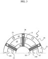
- FIG. 3 is a sectional view in an arrow direction taken along line III-III of FIG. 2
- the exhaust frame 4 according to this embodiment includes a casing 9, an upstream-side diffuser 10, strut 11, strut cover 12, a downstream-side diffuser 13 and communication holes 24.
- the casing 9 constitutes a part of a circumferential wall of the exhaust frame 4.
- the casing 9 includes an inner casing 9A and an outer casing 9B, with an annular space defined inside thereof.
- the upstream-side diffuser 10 is accommodated in the casing 9.
- the upstream-side diffuser 10 includes an inner diffuser 10A and an outer diffuser 10B.
- the inner casing 9A is a conical surface-shaped member which constitutes an inner circumferential wall of the casing 9.
- the inner diffuser 10A is a conical surface-shaped member formed such as to cover the outer side of the inner casing 9A, and constitutes an inner circumferential wall of the upstream-side diffuser 10.
- a final stage wheel 25 which includes final stage moving blades 27 of the turbine 3.
- the inner casing 9A and the inner diffuser 10A are spaced downstream from the final stage wheel 25 such as to secure a space (final stage wheel space) 21 between their upstream-side end portions and the final stage wheel 25.
- An annular space defined between the inner diffuser 10A and the inner casing 9A constitutes a passage (inner cooling passage) 16 through which cooling air supplied into the exhaust frame 4 flows.
- the inner cooling passage 16 communicates with the final stage wheel space 21.
- the outer diffuser 10B is a conical surface-shaped member formed such as to cover the outer side of the inner diffuser 10A, and constitutes an outer circumferential wall of the upstream-side diffuser 10.
- An annular space defined between the inner diffuser 10A and the outer diffuser 10B constitutes a passage (exhaust passage) 18 through which the combustion gas 7 from the turbine 3 flows.
- the outer casing 9B is a conical surface-shaped member formed such as to cover the outer side of the outer diffuser 10B, and constitutes an outer circumferential wall of the casing 9.
- An annular space defined between the outer diffuser 10B and the outer casing 9B constitutes a passage (outer cooling passage) 19 through which cooling air supplied into the exhaust frame 4 flows.
- the outer cooling passage 19 is provided with a cooling medium supply hole 15.
- the cooling medium supply hole 15 is a cooling air introduction hole provided in the outer cooling passage 19 at a position on the upstream side of connection passages 22 (described later). In this embodiment, a portion of the high-pressure air generated by the compressor 1 (see FIG. 1 ) is extracted and is supplied through the cooling medium supply hole 15 into the exhaust frame 4 as cooling air 23.
- the struts 11 are provided such as to cross the exhaust passage 18 at positions on the downstream side, in the inner diffuser 10A and the outer diffuser 10B, and connect the inner casing 9A and the outer casing 9B to each other.
- the outer casing 9B described above is supported by a turbine stand (not shown), and the struts 11 play the role of supporting the inner casing 9A relative to the outer casing 9B.
- the struts 11 are provided (in this embodiment, six) at regular intervals along the circumferential direction of the inner casing 9A. As shown in FIG.
- the struts 11 extend radially from the inner casing 9A in the radial directions of the casing 9 (in the directions from the inner casing 9A toward the outer casing 9B). It is to be noted, however, that the struts 11 may be provided to extend from the inner casing 9A in the state of being inclined in the circumferential direction in relation to the radial direction of the casing 9.
- the strut covers 12 connect the inner diffuser 10A and the outer diffuser 10B to each other, and are provided in such a manner that each strut cover 12 covers the outer side of the strut 11 as viewed in a section extending in the rotating direction (circumferential direction) of the turbine 3.
- Annular spaces each defined between the strut 11 and the strut cover 12 constitute passages (connection passages) 22 connecting the inner cooling passage 16 and the outer cooling passage 19 to each other.
- the downstream-side diffuser 13 is connected to the downstream side of the upstream-side diffuser 10 through a flange 20. A downstream-side end portion of the outer cooling passage 19 is closed with the flange 20 for the outer diffuser 10B and the downstream-side diffuser 13 that are connected to each other.
- the downstream-side diffuser 13 includes an inner diffuser 13A and an outer diffuser 13B.
- the inner diffuser 13A and the outer diffuser 13B are members which are formed in a trumpet shape such that an annular space defined therebetween is turned toward a radially outer side on the downstream side.
- the inner diffuser 13A and the outer diffuser 13B respectively constitute an inner circumferential wall and an outer circumferential wall of the downstream-side diffuser 13.
- At least one turn vane (in this embodiment, two turn vanes) 26 is provided inside the downstream-side diffuser 13.
- Each of the turn vanes 26 is provided in such a manner that its ventral side surface (positive-pressure surface, that is a surface hollowed in a concaved shape) is oriented toward the outer diffuser 13B side whereas its back side surface (negative-pressure surface, that is a surface projected in a convexed shape) is oriented toward the inner diffuser 13A side.
- the communication holes 24 are provided in a wall of the outer cooling passage 19 at positions on the downstream side of center lines X, which extend in the turbine radial directions, of the struts 11 in regard to the flow direction of the combustion gas 7.
- the communication holes 24 are provided on the downstream side of downstream edges 11B of the struts 11; specifically, the communication holes 24 are provided in the flange 20 by which the outer diffuser 10B and the downstream-side diffuser 13 are coupled to each other.
- the outer cooling passage 19 communicates with a space outside the downstream-side diffuser 13, namely, with the outside of gas turbine fluid systems such as systems of a working fluid, cooling air, sealing air, etc.
- the positions of the communication holes 24 are located on the downstream side of the center lines X of the struts 11, and, where the communication holes 24 are disposed on the downstream side of the downstream edges 11B of the struts 11, stagnation regions (which will be detailed later) inside the cooling passage can be thereby reduced.
- a plurality of the communication holes 24 are provided at intervals along the circumferential direction.
- the circumferential pitch of the communication holes 24 is set to be shorter than the circumferential pitch of the struts 11 which cross the outer cooling passage 19, such that at least one communication hole 24 is disposed between each pair of the adjacent struts 11.
- the communication holes 24 are each provided at each of the positions corresponding to the struts 11 and at each middle position between the adjacent struts 11, as viewed in the axial direction of the turbine. While one communication hole 24 is provided between the adjacent struts 11 in this embodiment, a plurality of the communication holes 24 may be provided between the adjacent struts 11. In this case, while the circumferential pitch of the communication holes 24 may be constant, the communication holes 24 may be unevenly distributed along the circumferential direction; for example, the communication holes 24 may be provided such that the circumferential density thereof is higher in the vicinity of the midpoint between the adjacent struts 11 and is lower in the vicinity of the struts 11.
- the opening area of the communication hole 24 is constant in this embodiment, the opening area of the communication hole 24 may be set to vary along the circumferential direction.
- the total opening area of the communication holes 24 is set such that most of the cooling air 23 supplied into the exhaust frame 4 is intercepted by the flange 20, and the flow rate of the cooling air 23 flowing out through the communication holes 24 can be suppressed to such an extent that its influence on gas turbine efficiency is negligible (for example, around 3% based on the total flow rate of the cooling air 23).
- the communication holes 24 are formed in such a manner that they can be closed with plugs or the like, by forming the communication holes 24 as threaded holes, for example.
- the combustion gas 7 produced in the combustor 2 flows into the turbine 3 in the state of a higher pressure (e.g., about 2 MPa) as compared to the atmospheric pressure, is lowered in pressure and temperature while performing a work at each stage of the turbine 3, and passes through the final-stage moving blades 27 to flow into the exhaust passage 18 (see FIG. 2 ).
- the combustion gas 7 at the time of flowing into the exhaust passage 18 has a pressure (e.g., about 0.09 MPa) having been lowered below the atmospheric pressure.
- the combustion gas 7 having flowed into the exhaust passage 18 is reduced in velocity in the process of flowing downstream (toward the outlet side) through the exhaust passage 18, and recovers pressure nearly to the atmospheric pressure.
- the cooling air 23 is an extracted portion of the high-pressure air produced in the compressor 1, and is supplied into the outer cooling passage 19 via the cooling medium supply hole 15 in the state of a high pressure (e.g., about 0.11 MPa). Since the combustion gas 7 flowing into the exhaust passage 18 has a pressure lower than the atmospheric pressure, the cooling air 23 supplied into the outer cooling passage 19 flows through the outer cooling passage 19, the connection passages 22 and the inner cooling passage 16 due to the pressure difference between its pressure and the internal pressure inside the exhaust passage 18, to join the combustion gas 7 flowing through the exhaust passage 18, by way of the final stage wheel space 21.
- a high pressure e.g., about 0.11 MPa
- the cooling air 23 flows along the casing 9, the upstream-side diffuser 10, the struts 11 and the strut covers 12 in a turning-back manner, whereby the casing 9, the upstream-side diffuser 10, the struts 11 and the strut covers 12 are effectively cooled.
- this is not restrictive; for example, other supply source such as a blower can also be used.
- FIG. 7 is a schematic configuration view of an exhaust frame according to a second embodiment.
- the equivalent parts to those in the first embodiment above are denoted by the same reference symbols as used above, and descriptions of them will be omitted appropriately.
- An exhaust frame 104 according to this embodiment differs from the exhaust frame 4 of the first embodiment in the position of communication holes. In other points of configuration, the exhaust frame 104 in this embodiment is the same as the exhaust frame 4 in the first embodiment.
- communication holes 28 are provided in the outer diffuser 10B at positions on the downstream side of the center lines X, which extend in the radial directions of the turbine, of the struts 11 in the flow direction of the combustion gas 7 (in the example illustrated, on the downstream side of downstream edges of the struts 11), and the outer cooling passage 19 communicates with the exhaust passage 18 through the communication holes 28.
- the internal pressure inside the outer cooling passage 19 is higher than the internal pressure inside the exhaust passage 18. Therefore, although the cooling air 23 having reached a downstream-side end portion of the outer cooling passage 19 mostly flows into the connection passages 22, part of the cooling air 23 is sucked into the communication holes 28 to join the combustion gas 7 flowing through the exhaust gas 18. As a result, the flow of the cooling air 23 in the vicinity of downstream edges of the struts 11 in the outer cooling passage 19 is accelerated, so that the flow rate and flow velocity of the cooling air 23 passing along the outer going-around flow path and flowing into the connection passages 22 are increased.
- the cooling air 23 having flowed through the outer cooling passage 19 and having cooled the outer diffuser 10B can be led into the exhaust passage 18, instead of into the space outside of the downstream-side diffuser 13. Therefore, the quantity of heat released to the external space from the gas turbine 100 (a diffusing heat quantity) can be decreased.
- the communication holes 28 are provided in the outer diffuser 10B which is thinner than the flange 20, the communication holes can be provided more easily than in the first embodiment.
- FIG. 8 is a schematic configuration view of an exhaust frame according to a third embodiment.
- the equivalent parts to those in the first embodiment above are denoted by the same reference symbols as used above, and descriptions of them will be omitted appropriately.
- An exhaust frame 204 according to this embodiment differs from the exhaust frame 4 of the first embodiment in the position of communication holes. In other points of configuration, the exhaust frame 204 in this embodiment is the same as the exhaust frame 4 in the first embodiment.
- communication holes 29 are provided in the outer casing 9B at positions on the downstream side of the center lines X, which extend in the radial directions of the turbine, of the struts 11 in the flow direction of the combustion gas 7, and the outer cooling passage 19 communicates with the space outside of the outer casing 9B through the outer casing 9B.
- the cooling air 23 flowing through the outer cooling passage 19 has a pressure higher than the atmospheric pressure whereas the air pressure in the space outside of the outer casing 9B is the atmospheric pressure, the internal pressure inside the outer cooling passage 19 is higher than the air pressure in the space outside of the outer casing 9B. Therefore, although the cooling air 23 having reached a downstream-side end portion of the outer cooling passage 19 mostly flows into the connection passages 22, part of the cooling air 23 is sucked into the communication holes 29. As a result, the flow of the cooling air 23 in the vicinity of downstream edges of the struts 11 in the outer cooling passage 19 is accelerated, so that the flow rate and flow velocity of the cooling air 23 passing along the outer going-around flow path and flowing into the connection passages 22 are increased.
- the present invention is not limited to the above-described embodiments, and includes various modifications.
- the above embodiments have been described in detail for easily understandable explanation of the present invention, and are not necessarily restricted to those having all the configurations described.
- part of the configurations of an embodiment may be replaced by a configuration of another embodiment, or part of the configurations of each embodiment may be omitted.
Landscapes
- Engineering & Computer Science (AREA)
- Mechanical Engineering (AREA)
- General Engineering & Computer Science (AREA)
- Chemical & Material Sciences (AREA)
- Combustion & Propulsion (AREA)
- Physics & Mathematics (AREA)
- Fluid Mechanics (AREA)
- Turbine Rotor Nozzle Sealing (AREA)
Abstract
Description
- The present invention relates to an exhaust frame for a gas turbine.
- In recent years, for enhancing the efficiency of a gas turbine, there has been a demand for a rising combustion temperature. A rise in the combustion temperature of a gas turbine is accompanied by a rise in the temperature of the exhaust gas from the turbine, and, as a result, the temperature of the exhaust frame into which the exhaust gas flows can also be raised. Therefore, it is necessary to efficiently cool the exhaust frame, for securing maintainability of the exhaust frame.
- As a method for cooling the exhaust frame, there is a method in which cooling air supplied into the exhaust frame via a cooling air supply hole is led to a final stage wheel space of the turbine by way of inter-strut spaces each of which is defined between a strut and a strut cover (see, for example,
JP-2005-83199-A - The inter-strut space is defined in a tubular shape such as to covert the strut which extends across the combustion gas passage at a position on the downstream side as compared to the cooling air supply hole and the final stage wheel space in the flow direction of the combustion gas. Therefore, as compared to the flow path length in the case of flowing by way of that portion of the inter-strut space which is the nearest to the cooling air supply hole (this portion will hereinafter be referred to as the near-side space), the flow path length in the case of flowing by way of that portion of the inter-strut space which is the farthest from the cooling air supply hole (this portion will hereinafter be referred to as the far-side space) is longer. In general, the pressure loss of cooling air which flows through a passage or flow path is smaller as the flow path length is shorter. In the case where the supply pressure of the cooling air is constant, the flow rate of the cooling air is increased as the pressure loss is reduced. In
JP-2005-83199-A - When the flow rate of the cooling air flowing by way of the far-side space is decreased, the cooling air becomes liable to stagnate in the passage in the vicinity of the inlet of the far-side space. In this case, the cooling efficiency for the exhaust frame may be lowered in the vicinity of the inlet of the far-side space.
- The present invention has been devised in view of the above and an object of the present invention is to restrain the cooling efficiency for an exhaust frame from being lowered.
- In order to achieve the object, the present invention provides an exhaust frame connected to an outlet for a combustion gas of a turbine, the exhaust frame including: an inner casing; an inner diffuser which covers an outer side of the inner casing and which defines, between the inner diffuser and the inner casing, an annular inner cooling passage connected to a final-stage wheel space of the turbine; an outer diffuser which covers an outer side of the inner diffuser and which defines an exhaust passage for the combustion gas between the outer diffuser and the inner diffuser; an outer casing which covers an outer side of the outer diffuser and which defines an annular outer cooling passage between the outer casing and the outer diffuser; a strut which connects the inner casing and the outer casing to each other while crossing the exhaust passage; a strut cover which connects the inner diffuser and the outer diffuser to each other, covers the strut, and which defines, between the strut cover and the strut, an annular connection passage connecting the inner cooling passage and the outer cooling passage to each other; and/ or a communication hole provided in a wall of the outer cooling passage at a position on a downstream side of a center line of the strut in a flow direction of the combustion gas.
- According to the present invention, it is possible to restrain the cooling efficiency for an exhaust frame from being lowered.
-
-
FIG. 1 illustrates a configuration example of a gas turbine provided with an exhaust frame according to a first embodiment of the present invention; -
FIG. 2 is a schematic configuration view of the exhaust frame according to the first embodiment of the present invention; -
FIG. 3 is a sectional view in an arrow direction taken along line III-III ofFIG. 2 ; -
FIG. 4 is a sectional view in an arrow direction taken along line IV-IV ofFIG. 2 ; -
FIG. 5 is a schematic configuration view of an exhaust frame according to a comparative example; -
FIG. 6 is a sectional view in an arrow direction taken along line VI-VI ofFIG. 5 ; -
FIG. 7 is a schematic configuration view of an exhaust frame according to a second embodiment of the present invention; and -
FIG. 8 is a schematic configuration view of an exhaust frame according to a third embodiment of the present invention. -
FIG. 1 illustrates a configuration example of a gas turbine provided with an exhaust frame according to a first embodiment. The exhaust frame according to this embodiment is applied, for example, to a heavy structure type gas turbine that is disposed on the ground and used mainly for power generation. - As shown in
FIG. 1 , thegas turbine 100 includes acompressor 1, acombustor 2, a turbine 3 and anexhaust frame 4. In this embodiment, thecompressor 1 and the turbine 3 are connected to each other through a shaft (not shown). Thecompressor 1, which is rotationally driven by the turbine 3, compressesair 6 sucked in through asuction part 5 to generate high-pressure air (combustion air), and supplies the high-pressure air to thecombustor 2. Thecombustor 2 mixes the high-pressure air supplied from thecompressor 1 with a fuel supplied from a fuel system (not shown), burns a resultant mixture to generate a high-temperature combustion gas 7, and supplies thecombustion gas 7 to the turbine 3. The turbine 3 is rotationally driven through expansion of thecombustion gas 7 supplied from thecombustor 2. The turbine 3 or thecompressor 1 is connected with a load apparatus (not shown). In this embodiment, a generator is connected to the turbine 3 as a load apparatus, and motive power obtained by subtracting motive power for driving thecompressor 1 from rotational power of the turbine 3 is converted into electric power by the generator. Thecombustion gas 7 having driven the turbine 3 flows into theexhaust frame 4 as a turbine exhaust gas, and is released to the atmospheric air via theexhaust frame 4 and an exhaust duct (not shown). - The
exhaust frame 4 is provided on the downstream side of the turbine 3 with respect to the flow direction of thecombustion gas 7, and connects an outlet for acombustion gas 7 of the turbine 3 and the exhaust duct to each other. The upstream and downstream with respect to the flow direction of thecombustion gas 7 will hereinafter referred to simply as "upstream" and "downstream," respectively. -
FIG. 2 is a schematic configuration view of the exhaust frame according to this embodiment, andFIG. 3 is a sectional view in an arrow direction taken along line III-III ofFIG. 2 . As illustrated inFIG. 2 , theexhaust frame 4 according to this embodiment includes acasing 9, an upstream-side diffuser 10,strut 11,strut cover 12, a downstream-side diffuser 13 andcommunication holes 24. - The
casing 9 constitutes a part of a circumferential wall of theexhaust frame 4. Thecasing 9 includes aninner casing 9A and anouter casing 9B, with an annular space defined inside thereof. The upstream-side diffuser 10 is accommodated in thecasing 9. The upstream-side diffuser 10 includes aninner diffuser 10A and anouter diffuser 10B. - The
inner casing 9A is a conical surface-shaped member which constitutes an inner circumferential wall of thecasing 9. - The
inner diffuser 10A is a conical surface-shaped member formed such as to cover the outer side of theinner casing 9A, and constitutes an inner circumferential wall of the upstream-side diffuser 10. On the upstream side of theinner casing 9A and theinner diffuser 10A, there is provided afinal stage wheel 25 which includes finalstage moving blades 27 of the turbine 3. Theinner casing 9A and theinner diffuser 10A are spaced downstream from thefinal stage wheel 25 such as to secure a space (final stage wheel space) 21 between their upstream-side end portions and thefinal stage wheel 25. An annular space defined between theinner diffuser 10A and theinner casing 9A constitutes a passage (inner cooling passage) 16 through which cooling air supplied into theexhaust frame 4 flows. Theinner cooling passage 16 communicates with the finalstage wheel space 21. - The
outer diffuser 10B is a conical surface-shaped member formed such as to cover the outer side of theinner diffuser 10A, and constitutes an outer circumferential wall of the upstream-side diffuser 10. An annular space defined between theinner diffuser 10A and theouter diffuser 10B constitutes a passage (exhaust passage) 18 through which thecombustion gas 7 from the turbine 3 flows. - The
outer casing 9B is a conical surface-shaped member formed such as to cover the outer side of theouter diffuser 10B, and constitutes an outer circumferential wall of thecasing 9. An annular space defined between theouter diffuser 10B and theouter casing 9B constitutes a passage (outer cooling passage) 19 through which cooling air supplied into theexhaust frame 4 flows. Theouter cooling passage 19 is provided with a coolingmedium supply hole 15. The coolingmedium supply hole 15 is a cooling air introduction hole provided in theouter cooling passage 19 at a position on the upstream side of connection passages 22 (described later). In this embodiment, a portion of the high-pressure air generated by the compressor 1 (seeFIG. 1 ) is extracted and is supplied through the coolingmedium supply hole 15 into theexhaust frame 4 ascooling air 23. - The
struts 11 are provided such as to cross theexhaust passage 18 at positions on the downstream side, in theinner diffuser 10A and theouter diffuser 10B, and connect theinner casing 9A and theouter casing 9B to each other. Theouter casing 9B described above is supported by a turbine stand (not shown), and thestruts 11 play the role of supporting theinner casing 9A relative to theouter casing 9B. Thestruts 11 are provided (in this embodiment, six) at regular intervals along the circumferential direction of theinner casing 9A. As shown inFIG. 3 , in this embodiment, thestruts 11 extend radially from theinner casing 9A in the radial directions of the casing 9 (in the directions from theinner casing 9A toward theouter casing 9B). It is to be noted, however, that thestruts 11 may be provided to extend from theinner casing 9A in the state of being inclined in the circumferential direction in relation to the radial direction of thecasing 9. - As shown in
FIG. 2 , the strut covers 12 connect theinner diffuser 10A and theouter diffuser 10B to each other, and are provided in such a manner that each strut cover 12 covers the outer side of thestrut 11 as viewed in a section extending in the rotating direction (circumferential direction) of the turbine 3. Annular spaces each defined between thestrut 11 and thestrut cover 12 constitute passages (connection passages) 22 connecting theinner cooling passage 16 and theouter cooling passage 19 to each other. - The downstream-
side diffuser 13 is connected to the downstream side of the upstream-side diffuser 10 through aflange 20. A downstream-side end portion of theouter cooling passage 19 is closed with theflange 20 for theouter diffuser 10B and the downstream-side diffuser 13 that are connected to each other. The downstream-side diffuser 13 includes aninner diffuser 13A and anouter diffuser 13B. Theinner diffuser 13A and theouter diffuser 13B are members which are formed in a trumpet shape such that an annular space defined therebetween is turned toward a radially outer side on the downstream side. Theinner diffuser 13A and theouter diffuser 13B respectively constitute an inner circumferential wall and an outer circumferential wall of the downstream-side diffuser 13. At least one turn vane (in this embodiment, two turn vanes) 26 is provided inside the downstream-side diffuser 13. Each of the turn vanes 26 is provided in such a manner that its ventral side surface (positive-pressure surface, that is a surface hollowed in a concaved shape) is oriented toward theouter diffuser 13B side whereas its back side surface (negative-pressure surface, that is a surface projected in a convexed shape) is oriented toward theinner diffuser 13A side. - The communication holes 24 are provided in a wall of the
outer cooling passage 19 at positions on the downstream side of center lines X, which extend in the turbine radial directions, of thestruts 11 in regard to the flow direction of thecombustion gas 7. In this embodiment, the communication holes 24 are provided on the downstream side ofdownstream edges 11B of thestruts 11; specifically, the communication holes 24 are provided in theflange 20 by which theouter diffuser 10B and the downstream-side diffuser 13 are coupled to each other. Through the communication holes 24, theouter cooling passage 19 communicates with a space outside the downstream-side diffuser 13, namely, with the outside of gas turbine fluid systems such as systems of a working fluid, cooling air, sealing air, etc. Note that it is important for the positions of the communication holes 24 to be located on the downstream side of the center lines X of thestruts 11, and, where the communication holes 24 are disposed on the downstream side of thedownstream edges 11B of thestruts 11, stagnation regions (which will be detailed later) inside the cooling passage can be thereby reduced. Besides, as shown inFIG. 3 , in this embodiment, a plurality of the communication holes 24 are provided at intervals along the circumferential direction. The circumferential pitch of the communication holes 24 is set to be shorter than the circumferential pitch of thestruts 11 which cross theouter cooling passage 19, such that at least onecommunication hole 24 is disposed between each pair of theadjacent struts 11. In this embodiment, the communication holes 24 are each provided at each of the positions corresponding to thestruts 11 and at each middle position between theadjacent struts 11, as viewed in the axial direction of the turbine. While onecommunication hole 24 is provided between theadjacent struts 11 in this embodiment, a plurality of the communication holes 24 may be provided between theadjacent struts 11. In this case, while the circumferential pitch of the communication holes 24 may be constant, the communication holes 24 may be unevenly distributed along the circumferential direction; for example, the communication holes 24 may be provided such that the circumferential density thereof is higher in the vicinity of the midpoint between theadjacent struts 11 and is lower in the vicinity of thestruts 11. While the opening area of thecommunication hole 24 is constant in this embodiment, the opening area of thecommunication hole 24 may be set to vary along the circumferential direction. The total opening area of the communication holes 24 is set such that most of the coolingair 23 supplied into theexhaust frame 4 is intercepted by theflange 20, and the flow rate of the coolingair 23 flowing out through the communication holes 24 can be suppressed to such an extent that its influence on gas turbine efficiency is negligible (for example, around 3% based on the total flow rate of the cooling air 23). The communication holes 24 are formed in such a manner that they can be closed with plugs or the like, by forming the communication holes 24 as threaded holes, for example. - The flow of the cooling
air 23 supplied to theexhaust frame 4 according to this embodiment will be described below. - The
combustion gas 7 produced in thecombustor 2 flows into the turbine 3 in the state of a higher pressure (e.g., about 2 MPa) as compared to the atmospheric pressure, is lowered in pressure and temperature while performing a work at each stage of the turbine 3, and passes through the final-stage moving blades 27 to flow into the exhaust passage 18 (seeFIG. 2 ). Thecombustion gas 7 at the time of flowing into theexhaust passage 18 has a pressure (e.g., about 0.09 MPa) having been lowered below the atmospheric pressure. Thecombustion gas 7 having flowed into theexhaust passage 18 is reduced in velocity in the process of flowing downstream (toward the outlet side) through theexhaust passage 18, and recovers pressure nearly to the atmospheric pressure. - The cooling
air 23 is an extracted portion of the high-pressure air produced in thecompressor 1, and is supplied into theouter cooling passage 19 via the coolingmedium supply hole 15 in the state of a high pressure (e.g., about 0.11 MPa). Since thecombustion gas 7 flowing into theexhaust passage 18 has a pressure lower than the atmospheric pressure, the coolingair 23 supplied into theouter cooling passage 19 flows through theouter cooling passage 19, theconnection passages 22 and theinner cooling passage 16 due to the pressure difference between its pressure and the internal pressure inside theexhaust passage 18, to join thecombustion gas 7 flowing through theexhaust passage 18, by way of the finalstage wheel space 21. In this way, the coolingair 23 flows along thecasing 9, the upstream-side diffuser 10, thestruts 11 and the strut covers 12 in a turning-back manner, whereby thecasing 9, the upstream-side diffuser 10, thestruts 11 and the strut covers 12 are effectively cooled. Note that an example wherein an extracted portion of the high-pressure air produced at thecompressor 1 is used as the coolingair 23 has been described in this embodiment, this is not restrictive; for example, other supply source such as a blower can also be used. -
- (1)
FIG. 5 is a schematic configuration view of an exhaust frame according to a comparative example, andFIG. 6 is a sectional view in an arrow direction taken along line VI-VI ofFIG. 5 . In the exhaust frame according to the comparative example, cooling air A supplied into an outer cooling passage F1 flows from the outer cooling passage F1 into connection passages F2, flows through the connection passages F2 into an inner cooling passage F3, and flows through the inner cooling passage F3 into an exhaust passage E. Here, as compared with the flow path length of an inner going-around flow path of going on the side of anupstream edge 11A of a strut S in the connection passage F2 of an outer diffuser D (namely, a flow path of going through points a, b, e and f inFIG. 5 ), the flow path length of an outer going-around flow path of going on the side of adownstream edge 11B of the strut S in the connection passage F2 (namely, a flow path of going through points a, b, c, d, e and f inFIG. 5 ) is longer. Therefore, the flow rate of the cooling air A flowing along the outer going-around flow path is smaller than the flow rate of the cooling air A flowing along the inner going-around flow path. In other words, the flow velocity of the cooling air A flowing along the outer going-around flow path to the side of thedownstream edges 11B of the struts S in the connection passages F2 is reduced. Consequently, as shown inFIG. 6 , stagnation regions P of the cooling air A are generated in the vicinity of inlets of the connection passages F2 on the side of thedownstream edges 11B between the adjacent struts S, and this can cause a lowering in the cooling efficiency for the exhaust frame.
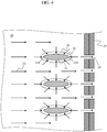
FIG. 4 is a sectional view in an arrow direction taken along line IV-IV ofFIG. 2 . As shown inFIG. 4 , in this embodiment, theflange 20 for coupling theouter diffuser 10B and the downstream-side diffuser 13 together is provided with the communication holes 24 through which theouter cooling passage 19 communicates with the space outside of the downstream-side diffuser 13. The internal pressure inside theouter cooling passage 19 is higher as compared with the pressure in the space outside of the downstream-side diffuser 13; therefore, although the coolingair 23 reaching a downstream-side end portion of theouter cooling passage 19 is mostly intercepted by theflange 20 and flows out into theconnection passages 22, part of the cooling air is sucked into the communication holes 24. By this, the flow of the coolingair 23 in the vicinity ofdownstream edges 11B of thestruts 11 in theouter cooling passage 19 can be accelerated, so that the flow rate and flow velocity of the coolingair 23 passing along the outer going-around flow path and flowing into theconnection passages 22 on the side of thedownstream edges 11B of thestruts 11 can be increased. In other words, the flow rate of the coolingair 23 flowing through the stagnation regions P shown inFIG. 6 relevant to the comparative example can be increased, whereby the cooling efficiency in the regions can be restrained from being lowered. Particularly, the stagnation regions in theouter cooling passage 19 are liable to be formed in the outer going-around flow path, namely, on the downstream side of the center lines X of thestruts 11; therefore, disposition of the communication holes 24 on the downstream side of the center lines X of thestruts 11 can be a countermeasure against the problem about the formation of the stagnation regions. Besides, with the positions of the communication holes 24 set on the downstream side of thedownstream edges 11B of thestruts 11, the flow rate of the coolingair 23 is increased, and the region in which the coolingair 23 is distributed is enlarged, whereby the stagnation regions can be reduced more. In addition, in this embodiment, since the communication holes 24 are provided also at positions between theadjacent struts 11, the stagnation of the coolingair 23 which is liable to be generated in the vicinity of inlets of theconnection passages 22 on the side of thedownstream edges 11B between theadjacent struts 11 can be effectively prevented. - (2) In the case where communication holes are not provided, as in the exhaust frame according to the comparative example, the
exhaust frame 4 according to this embodiment can be obtained by additionally providing the flange G with communication holes. Thus, theexhaust frame 4 according to this embodiment can be easily obtained by applying a simple working to an existing exhaust frame. - (3) In this embodiment, by providing the communication holes 24 through which the
outer cooling passage 19 communicates with the space outside of the downstream-side diffuser 13, it is possible to enhance the cooling efficiency for theexhaust frame 4. Therefore, maintainability of theexhaust frame 4 can be secured without using any highly heat-resistant material. Consequently, an increase in manufacturing cost can be suppressed, as compared to the case of manufacturing an exhaust frame by use of a valuable heat-resistant material. - (4) As a method for suppressing a rise in the temperature of an exhaust frame, there may be contemplated a method in which the flow rate of cooling air is increased or a method in which the number of struts is increased. According to the former method, however, in the case where an extracted portion of the high-pressure air produced at a compressor is used as a source of cooling air, the flow rate of the main flow gas is reduced, so that the gas turbine output is reduced and the efficiency is lowered. In the case where other element such as a blower is used as a cooling air supply source, also, the need to increase the blower capacity leads to an increase in cost. In addition, even if the flow rate of cooling air is increased, there still remains the tendency toward stagnation of cooling air in the vicinity of inlets of connection passages on the downstream side, and, therefore, it is difficult, by simply increasing the cooling air, to suppress the rise in the temperature of the exhaust frame. According to the latter method, by increasing the number of struts and thereby increasing the flow passage area of the connection passages, it is possible to lower the possibility of stagnation of cooling air and to suppress the rise in the temperature of the exhaust frame. However, the increase in the number of the struts which interfere with the flow of the combustion gas flowing through the diffuser may lower the performance of the diffuser.
On the other hand, in this embodiment, a lowering in the cooling efficiency for theexhaust frame 4 is restrained by providing theflange 20 with the communication holes 24 sized in such a manner as not to influence the gas turbine efficiency, without increasing the flow rate of the cooling air or increasing the number of the struts. In this case, therefore, a lowering in the gas turbine efficiency can be obviated, and a rise in the cost can be suppressed. In addition, a lowering in the diffuser performance can also be avoided. - (5) In this embodiment, the communication holes 24 are formed to be closable. Therefore, in the case of such an environment that stagnation of the cooling
air 23 inside theouter cooling passage 19 is not generated, for example, it is possible, by closing the communication holes 24, to restrain the coolingair 23 from being released to the space outside of the downstream-side diffuser 13. -
FIG. 7 is a schematic configuration view of an exhaust frame according to a second embodiment. InFIG. 7 , the equivalent parts to those in the first embodiment above are denoted by the same reference symbols as used above, and descriptions of them will be omitted appropriately. - An
exhaust frame 104 according to this embodiment differs from theexhaust frame 4 of the first embodiment in the position of communication holes. In other points of configuration, theexhaust frame 104 in this embodiment is the same as theexhaust frame 4 in the first embodiment. - In this embodiment, communication holes 28 are provided in the
outer diffuser 10B at positions on the downstream side of the center lines X, which extend in the radial directions of the turbine, of thestruts 11 in the flow direction of the combustion gas 7 (in the example illustrated, on the downstream side of downstream edges of the struts 11), and theouter cooling passage 19 communicates with theexhaust passage 18 through the communication holes 28. - Since the cooling
air 23 flowing through theouter cooling passage 19 has a pressure higher than the atmospheric pressure whereas thecombustion gas 7 flowing through theexhaust passage 18 has a pressure lower than the atmospheric pressure, the internal pressure inside theouter cooling passage 19 is higher than the internal pressure inside theexhaust passage 18. Therefore, although the coolingair 23 having reached a downstream-side end portion of theouter cooling passage 19 mostly flows into theconnection passages 22, part of the coolingair 23 is sucked into the communication holes 28 to join thecombustion gas 7 flowing through theexhaust gas 18. As a result, the flow of the coolingair 23 in the vicinity of downstream edges of thestruts 11 in theouter cooling passage 19 is accelerated, so that the flow rate and flow velocity of the coolingair 23 passing along the outer going-around flow path and flowing into theconnection passages 22 are increased. - In this embodiment, the following effects can be obtained, in addition to the same effects as in the first embodiment.
- In this embodiment, since the communication holes 28 are provided in the
outer diffuser 10B, the coolingair 23 having flowed through theouter cooling passage 19 and having cooled theouter diffuser 10B can be led into theexhaust passage 18, instead of into the space outside of the downstream-side diffuser 13. Therefore, the quantity of heat released to the external space from the gas turbine 100 (a diffusing heat quantity) can be decreased. - Besides, in this embodiment, since the communication holes 28 are provided in the
outer diffuser 10B which is thinner than theflange 20, the communication holes can be provided more easily than in the first embodiment. -
FIG. 8 is a schematic configuration view of an exhaust frame according to a third embodiment. InFIG. 8 , the equivalent parts to those in the first embodiment above are denoted by the same reference symbols as used above, and descriptions of them will be omitted appropriately. - An
exhaust frame 204 according to this embodiment differs from theexhaust frame 4 of the first embodiment in the position of communication holes. In other points of configuration, theexhaust frame 204 in this embodiment is the same as theexhaust frame 4 in the first embodiment. - In this embodiment, communication holes 29 are provided in the
outer casing 9B at positions on the downstream side of the center lines X, which extend in the radial directions of the turbine, of thestruts 11 in the flow direction of thecombustion gas 7, and theouter cooling passage 19 communicates with the space outside of theouter casing 9B through theouter casing 9B. - Since the cooling
air 23 flowing through theouter cooling passage 19 has a pressure higher than the atmospheric pressure whereas the air pressure in the space outside of theouter casing 9B is the atmospheric pressure, the internal pressure inside theouter cooling passage 19 is higher than the air pressure in the space outside of theouter casing 9B. Therefore, although the coolingair 23 having reached a downstream-side end portion of theouter cooling passage 19 mostly flows into theconnection passages 22, part of the coolingair 23 is sucked into the communication holes 29. As a result, the flow of the coolingair 23 in the vicinity of downstream edges of thestruts 11 in theouter cooling passage 19 is accelerated, so that the flow rate and flow velocity of the coolingair 23 passing along the outer going-around flow path and flowing into theconnection passages 22 are increased. - Even in the case where the communication holes 29 are provided in the
outer casing 9B, as in this embodiment, the same effects as in the first embodiment can be obtained. - The present invention is not limited to the above-described embodiments, and includes various modifications. For instance, the above embodiments have been described in detail for easily understandable explanation of the present invention, and are not necessarily restricted to those having all the configurations described. For instance, part of the configurations of an embodiment may be replaced by a configuration of another embodiment, or part of the configurations of each embodiment may be omitted.
- In each of the embodiments described above, a configuration wherein a plurality of communication holes 24 are arranged in the circumferential direction has been shown by way of example. However, the essential effect of the present invention is to restrain the cooling efficiency for the exhaust frame from being lowered, and the aforementioned configuration is not limitative, so long as this essential effect can be obtained. For instance, a configuration may be adopted wherein only one
communication hole 24 is arranged in the circumferential direction. - Features, components and specific details of the structures of the above-described embodiments may be exchanged or combined to form further embodiments optimized for the respective application. As far as those modifications are readily apparent for an expert skilled in the art they shall be disclosed implicitly by the above description without specifying explicitly every possible combination, for the sake of conciseness of the present description.
Claims (8)
- An exhaust frame (4) connected to an outlet for a combustion gas (7) of a turbine (3), the exhaust frame (4) comprising:an inner casing (9A);an inner diffuser (10A) that covers an outer side of the inner casing (9A) and defines, between the inner diffuser (10A) and the inner casing (9A), an annular inner cooling passage (16) connected to a final-stage wheel space (21) of the turbine (3);an outer diffuser (10B) that covers an outer side of the inner diffuser (10A) and defines an exhaust passage (18) for the combustion gas (7) between the outer diffuser (10B) and the inner diffuser (10A);an outer casing (9B) that covers an outer side of the outer diffuser (10B) and defines an annular outer cooling passage (19) between the outer casing (9B) and the outer diffuser (10B);a strut (11) that connects the inner casing (9A) and the outer casing (9B) to each other while crossing the exhaust passage (18); anda strut cover (12) that connects the inner diffuser (10A) and the outer diffuser (10B) to each other, covers the strut (11), and defines, between the strut cover (12) and the strut (11), an annular connection passage (22) connecting the inner cooling passage (16) and the outer cooling passage (19) to each other; characterized in that the exhaust frame (4) comprising:a communication hole (24; 28; 29) provided in a wall of the outer cooling passage (19) at a position on a downstream side of a center line (X) of the strut (11) in a flow direction of the combustion gas (7).
- The exhaust frame (4) according to claim 1,
wherein the communication hole (24; 28; 29) is provided at a position on the downstream side of a downstream edge of the strut (11). - The exhaust frame (4) according to claim 1,
wherein the outer cooling passage (19) is provided with a cooling air introduction hole (15) at a position on an upstream side in the flow direction of the combustion gas (7) as compared to the connection passage (22). - The exhaust frame (4) according to claim 1,
further comprising a downstream-side diffuser (13) connected to the outer diffuser (10B) at a position on the downstream side in the flow direction of the combustion gas (7),
wherein an end portion of the outer cooling passage (19) is closed with a flange (20) for the outer diffuser (10B) and the downstream-side diffuser (13) that are connected to each other, and
the communication hole (24) is provided in the flange (20) such that the outer cooling passage (19) communicates with a space outside of the downstream-side diffuser (13) through the flange (20). - The exhaust frame (4) according to claim 1,
wherein the communication hole (28) is provided in the outer diffuser (10B) such that the outer cooling passage (19) communicates with the exhaust passage (18) through the outer diffuser (10B). - The exhaust frame (4) according to claim 1,
wherein the communication hole (29) is provided in the outer casing (9B) such that the outer cooling passage (19) communicates with a space outside of the outer casing (9B) through the outer casing (9B). - The exhaust frame (4) according to claim 1,
wherein a plurality of the struts (11) are provided along the circumferential direction of the inner casing (9A), and
at least one of the communication holes (24; 28; 29) is provided between each pair of the adjacent struts (11). - The exhaust frame (4) according to claim 1,
wherein the communication hole (24; 28; 29) is formed in a closable manner.
Applications Claiming Priority (1)
| Application Number | Priority Date | Filing Date | Title |
|---|---|---|---|
| JP2016011010A JP6580494B2 (en) | 2016-01-22 | 2016-01-22 | Exhaust frame |
Publications (2)
| Publication Number | Publication Date |
|---|---|
| EP3196422A1 true EP3196422A1 (en) | 2017-07-26 |
| EP3196422B1 EP3196422B1 (en) | 2019-12-18 |
Family
ID=57881990
Family Applications (1)
| Application Number | Title | Priority Date | Filing Date |
|---|---|---|---|
| EP17152469.7A Active EP3196422B1 (en) | 2016-01-22 | 2017-01-20 | Exhaust frame |
Country Status (5)
| Country | Link |
|---|---|
| US (1) | US10422249B2 (en) |
| EP (1) | EP3196422B1 (en) |
| JP (1) | JP6580494B2 (en) |
| KR (1) | KR101981379B1 (en) |
| CN (1) | CN106996321B (en) |
Cited By (1)
| Publication number | Priority date | Publication date | Assignee | Title |
|---|---|---|---|---|
| GB2566498A (en) * | 2017-09-15 | 2019-03-20 | Gkn Aerospace Sweden Ab | Turbine exhaust case cooling |
Families Citing this family (3)
| Publication number | Priority date | Publication date | Assignee | Title |
|---|---|---|---|---|
| US10837316B2 (en) * | 2017-08-25 | 2020-11-17 | DOOSAN Heavy Industries Construction Co., LTD | High thermal response exhaust diffuser strut collar |
| CN107524524A (en) * | 2017-10-24 | 2017-12-29 | 江苏华强新能源科技有限公司 | A kind of high-efficiency gas turbine gas extraction system |
| KR102403823B1 (en) * | 2019-12-13 | 2022-05-30 | 두산에너빌리티 주식회사 | Strut structure with strip for exhaust diffuser and gas turbine having the same |
Citations (5)
| Publication number | Priority date | Publication date | Assignee | Title |
|---|---|---|---|---|
| US20030161718A1 (en) * | 2002-02-25 | 2003-08-28 | Honeywell International, Inc. | Thermally isolated housing in gas turbine engine |
| JP2005083199A (en) | 2003-09-04 | 2005-03-31 | Hitachi Ltd | Gas turbine equipment and cooling air feeding method |
| US20070089421A1 (en) * | 2005-10-25 | 2007-04-26 | General Electric Company | Assembly and method for cooling rear bearing and exhaust frame of gas turbine |
| EP2578816A2 (en) * | 2011-10-03 | 2013-04-10 | General Electric Company | Turbine exhaust section structures with internal flow passages |
| WO2014105492A1 (en) * | 2012-12-29 | 2014-07-03 | United Technologies Corporation | Passages to facilitate a secondary flow between components |
Family Cites Families (9)
| Publication number | Priority date | Publication date | Assignee | Title |
|---|---|---|---|---|
| US3631672A (en) * | 1969-08-04 | 1972-01-04 | Gen Electric | Eductor cooled gas turbine casing |
| JPS59173527A (en) * | 1983-03-22 | 1984-10-01 | Hitachi Ltd | Gas turbine exhaust frame cooling air system |
| JP5118496B2 (en) * | 2008-01-10 | 2013-01-16 | 三菱重工業株式会社 | Gas turbine exhaust structure and gas turbine |
| US8756911B1 (en) * | 2011-11-16 | 2014-06-24 | Florida Turbine Technologies, Inc. | Turbine exhaust cylinder and strut cooling |
| US10094285B2 (en) * | 2011-12-08 | 2018-10-09 | Siemens Aktiengesellschaft | Gas turbine outer case active ambient cooling including air exhaust into sub-ambient cavity |
| JP5646109B2 (en) * | 2012-02-27 | 2014-12-24 | 三菱日立パワーシステムズ株式会社 | gas turbine |
| US9611756B2 (en) * | 2012-11-02 | 2017-04-04 | General Electric Company | System and method for protecting components in a gas turbine engine with exhaust gas recirculation |
| US20150354382A1 (en) * | 2014-06-06 | 2015-12-10 | General Electric Company | Exhaust frame cooling via strut cooling passages |
| JP6399894B2 (en) * | 2014-10-29 | 2018-10-03 | 三菱日立パワーシステムズ株式会社 | Exhaust device and gas turbine |
-
2016
- 2016-01-22 JP JP2016011010A patent/JP6580494B2/en active Active
-
2017
- 2017-01-16 KR KR1020170006919A patent/KR101981379B1/en active IP Right Grant
- 2017-01-18 US US15/408,805 patent/US10422249B2/en active Active
- 2017-01-19 CN CN201710037420.0A patent/CN106996321B/en active Active
- 2017-01-20 EP EP17152469.7A patent/EP3196422B1/en active Active
Patent Citations (5)
| Publication number | Priority date | Publication date | Assignee | Title |
|---|---|---|---|---|
| US20030161718A1 (en) * | 2002-02-25 | 2003-08-28 | Honeywell International, Inc. | Thermally isolated housing in gas turbine engine |
| JP2005083199A (en) | 2003-09-04 | 2005-03-31 | Hitachi Ltd | Gas turbine equipment and cooling air feeding method |
| US20070089421A1 (en) * | 2005-10-25 | 2007-04-26 | General Electric Company | Assembly and method for cooling rear bearing and exhaust frame of gas turbine |
| EP2578816A2 (en) * | 2011-10-03 | 2013-04-10 | General Electric Company | Turbine exhaust section structures with internal flow passages |
| WO2014105492A1 (en) * | 2012-12-29 | 2014-07-03 | United Technologies Corporation | Passages to facilitate a secondary flow between components |
Cited By (3)
| Publication number | Priority date | Publication date | Assignee | Title |
|---|---|---|---|---|
| GB2566498A (en) * | 2017-09-15 | 2019-03-20 | Gkn Aerospace Sweden Ab | Turbine exhaust case cooling |
| GB2566498B (en) * | 2017-09-15 | 2021-02-17 | Gkn Aerospace Sweden Ab | Turbine exhaust case cooling |
| US11162385B2 (en) | 2017-09-15 | 2021-11-02 | Gkn Aerospace Sweden Ab | Turbine exhaust case cooling |
Also Published As
| Publication number | Publication date |
|---|---|
| JP6580494B2 (en) | 2019-09-25 |
| EP3196422B1 (en) | 2019-12-18 |
| JP2017129107A (en) | 2017-07-27 |
| US20170211424A1 (en) | 2017-07-27 |
| CN106996321B (en) | 2020-01-07 |
| CN106996321A (en) | 2017-08-01 |
| KR20170088296A (en) | 2017-08-01 |
| US10422249B2 (en) | 2019-09-24 |
| KR101981379B1 (en) | 2019-05-22 |
Similar Documents
| Publication | Publication Date | Title |
|---|---|---|
| US20200277862A1 (en) | Airfoil for a turbine engine | |
| US11655718B2 (en) | Blade with tip rail, cooling | |
| US20170248155A1 (en) | Centrifugal compressor diffuser passage boundary layer control | |
| US10830051B2 (en) | Engine component with film cooling | |
| JP6399894B2 (en) | Exhaust device and gas turbine | |
| EP3196422A1 (en) | Exhaust frame | |
| JP2009062976A (en) | Turbomachine with diffuser | |
| JP2009047411A (en) | Turbo machine diffuser | |
| US20180320530A1 (en) | Airfoil with tip rail cooling | |
| JP2016205383A (en) | Shroud assembly and shroud for gas turbine engine | |
| US10577943B2 (en) | Turbine engine airfoil insert | |
| US10605170B2 (en) | Engine component with film cooling | |
| US11391176B2 (en) | Method and apparatus for supplying cooling air to a turbine | |
| EP3273002A1 (en) | Impingement cooling of a blade platform | |
| US10563518B2 (en) | Gas turbine engine trailing edge ejection holes | |
| JP2015200211A (en) | Ventilation structure for turbine | |
| US10718217B2 (en) | Engine component with cooling passages | |
| JP2016510854A (en) | Hot streak alignment method for gas turbine durability | |
| JP2018500502A (en) | Diffuser for centrifugal compressor | |
| US10280785B2 (en) | Shroud assembly for a turbine engine | |
| CN106545364B (en) | Mixing chamber for turbine wheel space cooling | |
| US20180230812A1 (en) | Film hole arrangement for a turbine engine | |
| US20210277784A1 (en) | Turbomachine component for a gas turbine, turbomachine assembly and gas turbine having the same | |
| CN108691658B (en) | Turbine engine with platform cooling circuit | |
| US9745894B2 (en) | Compressor air provided to combustion chamber plenum and turbine guide vane |
Legal Events
| Date | Code | Title | Description |
|---|---|---|---|
| PUAI | Public reference made under article 153(3) epc to a published international application that has entered the european phase |
Free format text: ORIGINAL CODE: 0009012 |
|
| STAA | Information on the status of an ep patent application or granted ep patent |
Free format text: STATUS: REQUEST FOR EXAMINATION WAS MADE |
|
| 17P | Request for examination filed |
Effective date: 20170126 |
|
| AK | Designated contracting states |
Kind code of ref document: A1 Designated state(s): AL AT BE BG CH CY CZ DE DK EE ES FI FR GB GR HR HU IE IS IT LI LT LU LV MC MK MT NL NO PL PT RO RS SE SI SK SM TR |
|
| AX | Request for extension of the european patent |
Extension state: BA ME |
|
| RIN1 | Information on inventor provided before grant (corrected) |
Inventor name: KAWAI, RYO Inventor name: NAKAMURA, TETSUYA Inventor name: TAKEDA, TAKUYA Inventor name: NANATAKI, KENJI |
|
| GRAP | Despatch of communication of intention to grant a patent |
Free format text: ORIGINAL CODE: EPIDOSNIGR1 |
|
| STAA | Information on the status of an ep patent application or granted ep patent |
Free format text: STATUS: GRANT OF PATENT IS INTENDED |
|
| RIC1 | Information provided on ipc code assigned before grant |
Ipc: F01D 25/30 20060101ALI20190625BHEP Ipc: F01D 25/14 20060101ALI20190625BHEP Ipc: F01D 25/12 20060101AFI20190625BHEP Ipc: F01D 9/06 20060101ALI20190625BHEP |
|
| INTG | Intention to grant announced |
Effective date: 20190717 |
|
| GRAS | Grant fee paid |
Free format text: ORIGINAL CODE: EPIDOSNIGR3 |
|
| GRAA | (expected) grant |
Free format text: ORIGINAL CODE: 0009210 |
|
| STAA | Information on the status of an ep patent application or granted ep patent |
Free format text: STATUS: THE PATENT HAS BEEN GRANTED |
|
| RIN1 | Information on inventor provided before grant (corrected) |
Inventor name: NANATAKI, KENJI Inventor name: NAKAMURA, TETSUYA Inventor name: TAKEDA, TAKUYA Inventor name: KAWAI, RYO |
|
| AK | Designated contracting states |
Kind code of ref document: B1 Designated state(s): AL AT BE BG CH CY CZ DE DK EE ES FI FR GB GR HR HU IE IS IT LI LT LU LV MC MK MT NL NO PL PT RO RS SE SI SK SM TR |
|
| REG | Reference to a national code |
Ref country code: CH Ref legal event code: EP |
|
| REG | Reference to a national code |
Ref country code: DE Ref legal event code: R096 Ref document number: 602017009706 Country of ref document: DE |
|
| REG | Reference to a national code |
Ref country code: IE Ref legal event code: FG4D |
|
| REG | Reference to a national code |
Ref country code: AT Ref legal event code: REF Ref document number: 1214824 Country of ref document: AT Kind code of ref document: T Effective date: 20200115 |
|
| REG | Reference to a national code |
Ref country code: NL Ref legal event code: MP Effective date: 20191218 |
|
| PG25 | Lapsed in a contracting state [announced via postgrant information from national office to epo] |
Ref country code: LT Free format text: LAPSE BECAUSE OF FAILURE TO SUBMIT A TRANSLATION OF THE DESCRIPTION OR TO PAY THE FEE WITHIN THE PRESCRIBED TIME-LIMIT Effective date: 20191218 Ref country code: NO Free format text: LAPSE BECAUSE OF FAILURE TO SUBMIT A TRANSLATION OF THE DESCRIPTION OR TO PAY THE FEE WITHIN THE PRESCRIBED TIME-LIMIT Effective date: 20200318 Ref country code: GR Free format text: LAPSE BECAUSE OF FAILURE TO SUBMIT A TRANSLATION OF THE DESCRIPTION OR TO PAY THE FEE WITHIN THE PRESCRIBED TIME-LIMIT Effective date: 20200319 Ref country code: SE Free format text: LAPSE BECAUSE OF FAILURE TO SUBMIT A TRANSLATION OF THE DESCRIPTION OR TO PAY THE FEE WITHIN THE PRESCRIBED TIME-LIMIT Effective date: 20191218 Ref country code: LV Free format text: LAPSE BECAUSE OF FAILURE TO SUBMIT A TRANSLATION OF THE DESCRIPTION OR TO PAY THE FEE WITHIN THE PRESCRIBED TIME-LIMIT Effective date: 20191218 Ref country code: BG Free format text: LAPSE BECAUSE OF FAILURE TO SUBMIT A TRANSLATION OF THE DESCRIPTION OR TO PAY THE FEE WITHIN THE PRESCRIBED TIME-LIMIT Effective date: 20200318 Ref country code: FI Free format text: LAPSE BECAUSE OF FAILURE TO SUBMIT A TRANSLATION OF THE DESCRIPTION OR TO PAY THE FEE WITHIN THE PRESCRIBED TIME-LIMIT Effective date: 20191218 |
|
| REG | Reference to a national code |
Ref country code: LT Ref legal event code: MG4D |
|
| PG25 | Lapsed in a contracting state [announced via postgrant information from national office to epo] |
Ref country code: RS Free format text: LAPSE BECAUSE OF FAILURE TO SUBMIT A TRANSLATION OF THE DESCRIPTION OR TO PAY THE FEE WITHIN THE PRESCRIBED TIME-LIMIT Effective date: 20191218 Ref country code: HR Free format text: LAPSE BECAUSE OF FAILURE TO SUBMIT A TRANSLATION OF THE DESCRIPTION OR TO PAY THE FEE WITHIN THE PRESCRIBED TIME-LIMIT Effective date: 20191218 |
|
| PG25 | Lapsed in a contracting state [announced via postgrant information from national office to epo] |
Ref country code: AL Free format text: LAPSE BECAUSE OF FAILURE TO SUBMIT A TRANSLATION OF THE DESCRIPTION OR TO PAY THE FEE WITHIN THE PRESCRIBED TIME-LIMIT Effective date: 20191218 |
|
| PG25 | Lapsed in a contracting state [announced via postgrant information from national office to epo] |
Ref country code: CZ Free format text: LAPSE BECAUSE OF FAILURE TO SUBMIT A TRANSLATION OF THE DESCRIPTION OR TO PAY THE FEE WITHIN THE PRESCRIBED TIME-LIMIT Effective date: 20191218 Ref country code: NL Free format text: LAPSE BECAUSE OF FAILURE TO SUBMIT A TRANSLATION OF THE DESCRIPTION OR TO PAY THE FEE WITHIN THE PRESCRIBED TIME-LIMIT Effective date: 20191218 Ref country code: EE Free format text: LAPSE BECAUSE OF FAILURE TO SUBMIT A TRANSLATION OF THE DESCRIPTION OR TO PAY THE FEE WITHIN THE PRESCRIBED TIME-LIMIT Effective date: 20191218 Ref country code: RO Free format text: LAPSE BECAUSE OF FAILURE TO SUBMIT A TRANSLATION OF THE DESCRIPTION OR TO PAY THE FEE WITHIN THE PRESCRIBED TIME-LIMIT Effective date: 20191218 Ref country code: PT Free format text: LAPSE BECAUSE OF FAILURE TO SUBMIT A TRANSLATION OF THE DESCRIPTION OR TO PAY THE FEE WITHIN THE PRESCRIBED TIME-LIMIT Effective date: 20200513 |
|
| PG25 | Lapsed in a contracting state [announced via postgrant information from national office to epo] |
Ref country code: SM Free format text: LAPSE BECAUSE OF FAILURE TO SUBMIT A TRANSLATION OF THE DESCRIPTION OR TO PAY THE FEE WITHIN THE PRESCRIBED TIME-LIMIT Effective date: 20191218 Ref country code: IS Free format text: LAPSE BECAUSE OF FAILURE TO SUBMIT A TRANSLATION OF THE DESCRIPTION OR TO PAY THE FEE WITHIN THE PRESCRIBED TIME-LIMIT Effective date: 20200418 Ref country code: SK Free format text: LAPSE BECAUSE OF FAILURE TO SUBMIT A TRANSLATION OF THE DESCRIPTION OR TO PAY THE FEE WITHIN THE PRESCRIBED TIME-LIMIT Effective date: 20191218 |
|
| REG | Reference to a national code |
Ref country code: CH Ref legal event code: PL |
|
| REG | Reference to a national code |
Ref country code: DE Ref legal event code: R097 Ref document number: 602017009706 Country of ref document: DE |
|
| PG25 | Lapsed in a contracting state [announced via postgrant information from national office to epo] |
Ref country code: MC Free format text: LAPSE BECAUSE OF FAILURE TO SUBMIT A TRANSLATION OF THE DESCRIPTION OR TO PAY THE FEE WITHIN THE PRESCRIBED TIME-LIMIT Effective date: 20191218 |
|
| REG | Reference to a national code |
Ref country code: AT Ref legal event code: MK05 Ref document number: 1214824 Country of ref document: AT Kind code of ref document: T Effective date: 20191218 Ref country code: BE Ref legal event code: MM Effective date: 20200131 |
|
| PLBE | No opposition filed within time limit |
Free format text: ORIGINAL CODE: 0009261 |
|
| STAA | Information on the status of an ep patent application or granted ep patent |
Free format text: STATUS: NO OPPOSITION FILED WITHIN TIME LIMIT |
|
| PG25 | Lapsed in a contracting state [announced via postgrant information from national office to epo] |
Ref country code: ES Free format text: LAPSE BECAUSE OF FAILURE TO SUBMIT A TRANSLATION OF THE DESCRIPTION OR TO PAY THE FEE WITHIN THE PRESCRIBED TIME-LIMIT Effective date: 20191218 Ref country code: LU Free format text: LAPSE BECAUSE OF NON-PAYMENT OF DUE FEES Effective date: 20200120 Ref country code: DK Free format text: LAPSE BECAUSE OF FAILURE TO SUBMIT A TRANSLATION OF THE DESCRIPTION OR TO PAY THE FEE WITHIN THE PRESCRIBED TIME-LIMIT Effective date: 20191218 |
|
| 26N | No opposition filed |
Effective date: 20200921 |
|
| PG25 | Lapsed in a contracting state [announced via postgrant information from national office to epo] |
Ref country code: SI Free format text: LAPSE BECAUSE OF FAILURE TO SUBMIT A TRANSLATION OF THE DESCRIPTION OR TO PAY THE FEE WITHIN THE PRESCRIBED TIME-LIMIT Effective date: 20191218 Ref country code: LI Free format text: LAPSE BECAUSE OF NON-PAYMENT OF DUE FEES Effective date: 20200131 Ref country code: AT Free format text: LAPSE BECAUSE OF FAILURE TO SUBMIT A TRANSLATION OF THE DESCRIPTION OR TO PAY THE FEE WITHIN THE PRESCRIBED TIME-LIMIT Effective date: 20191218 Ref country code: CH Free format text: LAPSE BECAUSE OF NON-PAYMENT OF DUE FEES Effective date: 20200131 Ref country code: BE Free format text: LAPSE BECAUSE OF NON-PAYMENT OF DUE FEES Effective date: 20200131 |
|
| REG | Reference to a national code |
Ref country code: DE Ref legal event code: R082 Ref document number: 602017009706 Country of ref document: DE Representative=s name: MERH-IP MATIAS ERNY REICHL HOFFMANN PATENTANWA, DE Ref country code: DE Ref legal event code: R081 Ref document number: 602017009706 Country of ref document: DE Owner name: MITSUBISHI POWER, LTD., JP Free format text: FORMER OWNER: MITSUBISHI HITACHI POWER SYSTEMS, LTD., YOKOHAMA, KANAGAWA, JP |
|
| PG25 | Lapsed in a contracting state [announced via postgrant information from national office to epo] |
Ref country code: IE Free format text: LAPSE BECAUSE OF NON-PAYMENT OF DUE FEES Effective date: 20200120 Ref country code: IT Free format text: LAPSE BECAUSE OF FAILURE TO SUBMIT A TRANSLATION OF THE DESCRIPTION OR TO PAY THE FEE WITHIN THE PRESCRIBED TIME-LIMIT Effective date: 20191218 |
|
| PG25 | Lapsed in a contracting state [announced via postgrant information from national office to epo] |
Ref country code: PL Free format text: LAPSE BECAUSE OF FAILURE TO SUBMIT A TRANSLATION OF THE DESCRIPTION OR TO PAY THE FEE WITHIN THE PRESCRIBED TIME-LIMIT Effective date: 20191218 |
|
| PG25 | Lapsed in a contracting state [announced via postgrant information from national office to epo] |
Ref country code: TR Free format text: LAPSE BECAUSE OF FAILURE TO SUBMIT A TRANSLATION OF THE DESCRIPTION OR TO PAY THE FEE WITHIN THE PRESCRIBED TIME-LIMIT Effective date: 20191218 Ref country code: MT Free format text: LAPSE BECAUSE OF FAILURE TO SUBMIT A TRANSLATION OF THE DESCRIPTION OR TO PAY THE FEE WITHIN THE PRESCRIBED TIME-LIMIT Effective date: 20191218 Ref country code: CY Free format text: LAPSE BECAUSE OF FAILURE TO SUBMIT A TRANSLATION OF THE DESCRIPTION OR TO PAY THE FEE WITHIN THE PRESCRIBED TIME-LIMIT Effective date: 20191218 |
|
| PG25 | Lapsed in a contracting state [announced via postgrant information from national office to epo] |
Ref country code: MK Free format text: LAPSE BECAUSE OF FAILURE TO SUBMIT A TRANSLATION OF THE DESCRIPTION OR TO PAY THE FEE WITHIN THE PRESCRIBED TIME-LIMIT Effective date: 20191218 |
|
| PGFP | Annual fee paid to national office [announced via postgrant information from national office to epo] |
Ref country code: GB Payment date: 20231130 Year of fee payment: 8 |
|
| PGFP | Annual fee paid to national office [announced via postgrant information from national office to epo] |
Ref country code: FR Payment date: 20231212 Year of fee payment: 8 |
|
| PGFP | Annual fee paid to national office [announced via postgrant information from national office to epo] |
Ref country code: DE Payment date: 20231128 Year of fee payment: 8 |