EP3196337A1 - Film-formation device and film-formation method - Google Patents
Film-formation device and film-formation method Download PDFInfo
- Publication number
- EP3196337A1 EP3196337A1 EP15842589.2A EP15842589A EP3196337A1 EP 3196337 A1 EP3196337 A1 EP 3196337A1 EP 15842589 A EP15842589 A EP 15842589A EP 3196337 A1 EP3196337 A1 EP 3196337A1
- Authority
- EP
- European Patent Office
- Prior art keywords
- zones
- substrate
- film formation
- chamber
- gas
- Prior art date
- Legal status (The legal status is an assumption and is not a legal conclusion. Google has not performed a legal analysis and makes no representation as to the accuracy of the status listed.)
- Granted
Links
Images


Classifications
-
- C—CHEMISTRY; METALLURGY
- C23—COATING METALLIC MATERIAL; COATING MATERIAL WITH METALLIC MATERIAL; CHEMICAL SURFACE TREATMENT; DIFFUSION TREATMENT OF METALLIC MATERIAL; COATING BY VACUUM EVAPORATION, BY SPUTTERING, BY ION IMPLANTATION OR BY CHEMICAL VAPOUR DEPOSITION, IN GENERAL; INHIBITING CORROSION OF METALLIC MATERIAL OR INCRUSTATION IN GENERAL
- C23C—COATING METALLIC MATERIAL; COATING MATERIAL WITH METALLIC MATERIAL; SURFACE TREATMENT OF METALLIC MATERIAL BY DIFFUSION INTO THE SURFACE, BY CHEMICAL CONVERSION OR SUBSTITUTION; COATING BY VACUUM EVAPORATION, BY SPUTTERING, BY ION IMPLANTATION OR BY CHEMICAL VAPOUR DEPOSITION, IN GENERAL
- C23C16/00—Chemical coating by decomposition of gaseous compounds, without leaving reaction products of surface material in the coating, i.e. chemical vapour deposition [CVD] processes
- C23C16/44—Chemical coating by decomposition of gaseous compounds, without leaving reaction products of surface material in the coating, i.e. chemical vapour deposition [CVD] processes characterised by the method of coating
- C23C16/455—Chemical coating by decomposition of gaseous compounds, without leaving reaction products of surface material in the coating, i.e. chemical vapour deposition [CVD] processes characterised by the method of coating characterised by the method used for introducing gases into reaction chamber or for modifying gas flows in reaction chamber
- C23C16/45523—Pulsed gas flow or change of composition over time
- C23C16/45525—Atomic layer deposition [ALD]
- C23C16/45544—Atomic layer deposition [ALD] characterized by the apparatus
-
- C—CHEMISTRY; METALLURGY
- C23—COATING METALLIC MATERIAL; COATING MATERIAL WITH METALLIC MATERIAL; CHEMICAL SURFACE TREATMENT; DIFFUSION TREATMENT OF METALLIC MATERIAL; COATING BY VACUUM EVAPORATION, BY SPUTTERING, BY ION IMPLANTATION OR BY CHEMICAL VAPOUR DEPOSITION, IN GENERAL; INHIBITING CORROSION OF METALLIC MATERIAL OR INCRUSTATION IN GENERAL
- C23C—COATING METALLIC MATERIAL; COATING MATERIAL WITH METALLIC MATERIAL; SURFACE TREATMENT OF METALLIC MATERIAL BY DIFFUSION INTO THE SURFACE, BY CHEMICAL CONVERSION OR SUBSTITUTION; COATING BY VACUUM EVAPORATION, BY SPUTTERING, BY ION IMPLANTATION OR BY CHEMICAL VAPOUR DEPOSITION, IN GENERAL
- C23C16/00—Chemical coating by decomposition of gaseous compounds, without leaving reaction products of surface material in the coating, i.e. chemical vapour deposition [CVD] processes
- C23C16/44—Chemical coating by decomposition of gaseous compounds, without leaving reaction products of surface material in the coating, i.e. chemical vapour deposition [CVD] processes characterised by the method of coating
- C23C16/4412—Details relating to the exhausts, e.g. pumps, filters, scrubbers, particle traps
-
- C—CHEMISTRY; METALLURGY
- C23—COATING METALLIC MATERIAL; COATING MATERIAL WITH METALLIC MATERIAL; CHEMICAL SURFACE TREATMENT; DIFFUSION TREATMENT OF METALLIC MATERIAL; COATING BY VACUUM EVAPORATION, BY SPUTTERING, BY ION IMPLANTATION OR BY CHEMICAL VAPOUR DEPOSITION, IN GENERAL; INHIBITING CORROSION OF METALLIC MATERIAL OR INCRUSTATION IN GENERAL
- C23C—COATING METALLIC MATERIAL; COATING MATERIAL WITH METALLIC MATERIAL; SURFACE TREATMENT OF METALLIC MATERIAL BY DIFFUSION INTO THE SURFACE, BY CHEMICAL CONVERSION OR SUBSTITUTION; COATING BY VACUUM EVAPORATION, BY SPUTTERING, BY ION IMPLANTATION OR BY CHEMICAL VAPOUR DEPOSITION, IN GENERAL
- C23C16/00—Chemical coating by decomposition of gaseous compounds, without leaving reaction products of surface material in the coating, i.e. chemical vapour deposition [CVD] processes
- C23C16/44—Chemical coating by decomposition of gaseous compounds, without leaving reaction products of surface material in the coating, i.e. chemical vapour deposition [CVD] processes characterised by the method of coating
- C23C16/455—Chemical coating by decomposition of gaseous compounds, without leaving reaction products of surface material in the coating, i.e. chemical vapour deposition [CVD] processes characterised by the method of coating characterised by the method used for introducing gases into reaction chamber or for modifying gas flows in reaction chamber
- C23C16/45523—Pulsed gas flow or change of composition over time
- C23C16/45525—Atomic layer deposition [ALD]
- C23C16/45544—Atomic layer deposition [ALD] characterized by the apparatus
- C23C16/45548—Atomic layer deposition [ALD] characterized by the apparatus having arrangements for gas injection at different locations of the reactor for each ALD half-reaction
- C23C16/45551—Atomic layer deposition [ALD] characterized by the apparatus having arrangements for gas injection at different locations of the reactor for each ALD half-reaction for relative movement of the substrate and the gas injectors or half-reaction reactor compartments
-
- C—CHEMISTRY; METALLURGY
- C23—COATING METALLIC MATERIAL; COATING MATERIAL WITH METALLIC MATERIAL; CHEMICAL SURFACE TREATMENT; DIFFUSION TREATMENT OF METALLIC MATERIAL; COATING BY VACUUM EVAPORATION, BY SPUTTERING, BY ION IMPLANTATION OR BY CHEMICAL VAPOUR DEPOSITION, IN GENERAL; INHIBITING CORROSION OF METALLIC MATERIAL OR INCRUSTATION IN GENERAL
- C23C—COATING METALLIC MATERIAL; COATING MATERIAL WITH METALLIC MATERIAL; SURFACE TREATMENT OF METALLIC MATERIAL BY DIFFUSION INTO THE SURFACE, BY CHEMICAL CONVERSION OR SUBSTITUTION; COATING BY VACUUM EVAPORATION, BY SPUTTERING, BY ION IMPLANTATION OR BY CHEMICAL VAPOUR DEPOSITION, IN GENERAL
- C23C16/00—Chemical coating by decomposition of gaseous compounds, without leaving reaction products of surface material in the coating, i.e. chemical vapour deposition [CVD] processes
- C23C16/44—Chemical coating by decomposition of gaseous compounds, without leaving reaction products of surface material in the coating, i.e. chemical vapour deposition [CVD] processes characterised by the method of coating
- C23C16/52—Controlling or regulating the coating process
-
- C—CHEMISTRY; METALLURGY
- C23—COATING METALLIC MATERIAL; COATING MATERIAL WITH METALLIC MATERIAL; CHEMICAL SURFACE TREATMENT; DIFFUSION TREATMENT OF METALLIC MATERIAL; COATING BY VACUUM EVAPORATION, BY SPUTTERING, BY ION IMPLANTATION OR BY CHEMICAL VAPOUR DEPOSITION, IN GENERAL; INHIBITING CORROSION OF METALLIC MATERIAL OR INCRUSTATION IN GENERAL
- C23C—COATING METALLIC MATERIAL; COATING MATERIAL WITH METALLIC MATERIAL; SURFACE TREATMENT OF METALLIC MATERIAL BY DIFFUSION INTO THE SURFACE, BY CHEMICAL CONVERSION OR SUBSTITUTION; COATING BY VACUUM EVAPORATION, BY SPUTTERING, BY ION IMPLANTATION OR BY CHEMICAL VAPOUR DEPOSITION, IN GENERAL
- C23C16/00—Chemical coating by decomposition of gaseous compounds, without leaving reaction products of surface material in the coating, i.e. chemical vapour deposition [CVD] processes
- C23C16/44—Chemical coating by decomposition of gaseous compounds, without leaving reaction products of surface material in the coating, i.e. chemical vapour deposition [CVD] processes characterised by the method of coating
- C23C16/54—Apparatus specially adapted for continuous coating
- C23C16/545—Apparatus specially adapted for continuous coating for coating elongated substrates
Definitions
- the present invention relates to film formation apparatuses and film formation methods.
- Atomic layer deposition has been proposed as an example of a film formation method.
- Atomic layer deposition which is referred to as ALD, is a film formation process in which layers are deposited in a layer-by-layer manner at an atomic level by chemically reacting the substances which are adsorbed on the surface.
- a highly reactive gas which is referred to as a precursor, and a reactive gas are alternately used to perform adsorption on the substrate surface and chemical reactions subsequent to the adsorption to thereby grow thin layers in a layer-by-layer manner at an atomic level.
- the reactive gas is also called a precursor in the ALD process.
- the ALD is characterized by having fewer defects in film formation, and is expected to be applied to various fields.
- a film formation apparatus and a film formation method of a time-divided type have been proposed, in which supply and discharge of precursors are repeatedly performed in a single chamber.
- the film formation apparatus and the film formation method of a time-divided type have a problem of a slow speed of film formation, since one layer is deposited in each cycle at an atomic level.
- a space-divided type in which the chamber is divided into a several zones (areas) so that a single precursor or purge gas is supplied into the respective zones while the substrate is reciprocated among the zones (e.g., see PTL 1).
- the ALD process of a space-divided type significantly improves the speed of film formation.
- each zone has at least one supply port that supplies gas and one discharge port that discharges gas so that the gas is supplied and discharged to be distributed at a desired concentration.
- the zones in the chamber have an area in which the gas is not sufficiently supplied. This causes difficulty in achieving saturated adsorption of the precursor across the entire surface of the substrate. As a consequence, the film thickness may vary depending on the sites on the substrate.
- a film formation apparatus is characterized in that the film formation apparatus includes: a chamber which includes a plurality of zones into which gas is introduced, and a plurality of discharge ports that discharge the gas located in at least any of the zones and that can individually adjust an opening state; and a transportation unit that transports a substrate so as to pass through the plurality of the zones in the chamber.
- a film formation method is characterized in that the film formation method includes: in a chamber which includes a plurality of zones into which gas is introduced, and a plurality of discharge ports that discharge the gas located in at least any of the zones and that can individually adjust an opening state, introducing the gas into the plurality of zones; and transporting the substrate in the chamber so as to pass through the plurality of the zones.
- the distribution of gas in each zone in the chamber can be homogenized, thereby improving film formation precision.
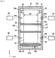
- Fig. 1 is a cross sectional view of a film formation apparatus 1 according to a first embodiment, and shows a configuration inside a chamber 20 in a front view.
- Fig. 2 is a cross sectional view taken along the line II-II' of Fig. 1 , and shows a configuration inside the chamber 20 in a side view.
- Fig. 3 is a cross sectional view taken along the line III-III' of Fig. 1 , and shows a configuration inside the chamber 20 in a plan view.
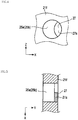
- Figs. 4 and 5 are a side view and a cross sectional view of an opening adjustment mechanism, respectively.
- the arrows X, Y, and Z in the figures indicate three directions which are perpendicular to one another. For convenience of description, the configuration shown in each figure is enlarged, reduced or omitted as appropriate.
- the film formation apparatus 1 shown in Figs. 1 to 3 is an ALD film formation apparatus 1 that forms a film on a substrate by means of atomic layer deposition (ALD).
- the film formation apparatus 1 is a space-divided type in which the chamber 20 is divided into a plurality of zones such that a single precursor or purge gas is supplied to each of the zones Z1 to Z3 while the substrate reciprocates among the zones Z1 to Z3.
- a flexible substrate 10 having a predetermined width (dimension in the Y direction) W1 and a thickness t1 is used as a substrate.
- a material of the substrate is selected from, but is not limited to, flexible materials such as a plastic film, plastic sheet, metal foil, metal sheet, paper, and non-woven cloth.
- the thickness of the substrate is, but is not limited to, in the range of 10 ⁇ m or more and 1000 ⁇ m or less.
- the flexible substrate 10 which is a flexible sheet having a small thickness relative to the width, is supplied from a supply chamber 41 provided on one side of the chamber 20 and is transported to a recovery chamber 42 provided on the other side of the chamber 20 via a traveling path P which reciprocates among the plurality of divided zones Z1, Z2, and Z3 multiple times.
- a so-called roll-to-roll method is used for the transportation in which the sheet shaped flexible substrate 10 wound into a roll is fed out from a supply roll 31, transported while forming a film, and taken up by a recovery roll 34.
- the film formation apparatus 1 includes the chamber 20 having the plurality of zones Z1, Z2, and Z3, a transportation unit 30 that transports the flexible substrate 10 along a predetermined traveling path P, and a control unit 50 that controls the operation of each component.
- the chamber 20 has upper and lower walls 21a and 21b, and side walls 21c, 21d, 21e, and 21f, each having a rectangular shape. These walls 21a to 21f define an inner space of a cuboid shape.
- the supply chamber 41 and the recovery chamber 42 are disposed adjacent to one side wall 21c of the chamber 20 and the opposed side wall 21d, respectively.
- partition walls 22 and 23 are disposed at two positions in the Z direction so as to form two surfaces extending along the XY plane.
- One partition wall 22 separates the first zone Z1 from the third zone Z3
- the other partition wall 23 separates the third zone Z3 from the second zone Z2.
- the chamber 20 is divided into the first zone Z1 that forms a first vacuum chamber into which a first precursor gas is introduced, the second zone Z2 that forms a second vacuum chamber into which a second precursor gas is introduced, and a third zone Z3 that is interposed between the first zone Z1 and the second zone Z2 and forms a third vacuum chamber into which a purge gas is introduced.
- the first precursor introduced into the first zone Z1 is appropriately selected depending on a target deposition material.
- a target deposition material for example, trimethylaluminum is used when a material to be deposited on the flexible substrate 10 (target deposition material) is aluminum oxide.
- the second precursor introduced into the second zone Z2 is appropriately selected depending on the target deposition material.
- the target deposition material is aluminum oxide.
- an inert gas As a purge gas introduced into the third zone Z3, an inert gas is used.
- the inert gas may be a gas appropriately selected from nitrogen, helium, argon and the like.
- the partition walls 22 and 23 has a plurality of slit shaped passage openings 22a and 23a which allow the flexible substrate 10 to pass through.
- the passage openings 22a and 23a penetrate through the partition walls 22 and 23 in the Z direction.
- 11 passage openings 22a and 23a are formed corresponding to the traveling path P which reciprocates six times.
- the traveling path P has a zigzag shape which includes a plurality of curved paths which turns over in the first zone Z1 and the second zone Z2 and straight paths which extend in the Z direction between the curved paths in the first zone Z1 and the curved paths in the second zone. These paths are juxtaposed side by side in the X direction.
- the traveling path P reciprocates between the first zone Z1 and the second zone Z2 multiple times, by which each cycle of sequentially passing through the first zone Z1, the third zone Z3, and the second zone Z2 and going back to the third zone is repeated multiple times.
- a supply ports 24 are disposed in the side wall 21e on one side of the chamber 20 in the Y direction.
- the supply ports 24 include supply ports 24a in the first zone Z1 for supplying the first precursor gas, and supply ports 24b in the second zone Z2 for supplying the second precursor gas.
- the supply ports 24a and 24b are located on one side in the width direction with respect to the traveling flexible substrate 10.
- the supply ports 24a and 24b communicate with a supply chamber 29 which is a supply unit of gas. Through the supply ports 24a and 24b, gas is supplied into the chamber 20.
- a plurality of supply ports 24a and 24b are disposed in the first zone Z1 and the second zone Z2 so as to correspond to the traveling path P which passes through the zones Z1 and Z2 multiple times.
- a total of 12 supply ports 24a and 24b are arranged side by side in the X direction such that each of the supply ports 24a and 24b correspond to each of the surfaces 10a and 10b of the substrate 10 in the plurality of straight paths which are arranged side by side in the X direction between guide rolls 32 and 33.
- the first precursor gas is introduced into the first zone Z1 through the supply port 24a in the first zone Z1
- the second precursor gas is introduced into the second zone Z2 through the supply port 24b in the second zone Z2.
- a plurality of discharge ports 25 are disposed in the side wall 21f on the other side of the chamber 20 in the Y direction.
- the discharge ports 25 include discharge ports 25a disposed in the first zone Z1 so as to discharge the first precursor gas, and discharge ports 25b disposed in the second zone Z2 so as to discharge the second precursor gas.
- the discharge ports 25 are located on the other side in the width direction (Y direction) of the traveling flexible substrate 10.
- the discharge ports 25a and 25b are connected to a vacuum pump 28 which is a discharge unit. The gas inside the chamber 20 is externally discharged from the chamber 20 via the discharge ports 25a and 25b by operation of the vacuum pump 28.
- the plurality of discharge ports 25 is disposed so as to correspond to the traveling path P which passes through the first zone Z1 and the second zone Z2 multiple times.
- a total of 12 discharge ports 25 are arranged side by side in the X direction such that each of the discharge ports 25 correspond to each of both surfaces 10a and 10b of the substrate in the plurality of straight paths which are arranged side by side in the X direction between guide rolls 32 and 33. That is, the first precursor gas in the first zone Z1 is externally discharged via the discharge ports 25a of the first zone Z1. The second precursor gas in the second zone Z2 is externally discharged via the discharge ports 25b of the second zone Z2.
- the discharge ports 25a and 25b each have an opening adjustment mechanism 27 so that their opening states can be individually adjusted.
- the opening adjustment mechanism 27 has a shutter mechanism having a shutter 27a that changes an opening rate by partially closing the opening of the discharge ports 25a and 25b.
- the opening adjustment mechanism 27 may use a butterfly valve mechanism that opens and closes to change the flow of gas.
- the opening adjustment mechanism 27 can individually adjust the opening rates of the plurality of discharge ports 25a and 25b to adjust the conductance of gas and control the flow of gas, thereby adjusting the concentration of gas.
- gas in the first zone Z1 and the second zone Z2 is discharged by the vacuum pump 28 through the discharge ports 25a and 25b, respectively.
- the pressure in the third zone Z3 is held higher than the pressure in the first zone Z1 and the second zone Z2. Accordingly, the first precursor gas and the second precursor gas introduced in the first zone Z1 and the second zone Z2, respectively, are maintained under conditions that do not allow these gases to easily diffuse into the third zone Z3.
- the transportation unit 30 includes the supply roll 31 disposed in the supply chamber 41, the plurality of first guide rolls 32 arranged in the first zone Z1 in the chamber 20, the plurality of second guide rolls 33 arranged in the second zone in the chamber 20, and the recovery roll 34 disposed in the recovery chamber 42.
- the supply roll 31 is formed in a columnar or cylindrical shape and has a rotation shaft 31a extending in the Y direction.
- the flexible substrate 10 before film formation is wound around the outer peripheral surface of the supply roll 31.
- the supply roll 31 rotates under control of the control unit 50, the flexible substrate 10 is fed out in the arrow direction shown in the figure.
- the recovery roll 34 is formed in a columnar or cylindrical shape and has a rotation shaft 34a extending in the Y direction. As the recovery roll 34 rotates about the shaft controlled by the control unit 50, the flexible substrate 10 is recovered by the recovery roll 34 after film formation by being wound around the outer peripheral surface of the recovery roll 34.
- the first guide rolls 32 and the second guide rolls 33 are formed in a columnar or cylindrical shape and have respective rotation shafts 32a and 33a extending in the Y direction.
- the plurality of first guide rolls 32 and the plurality of second guide rolls 33 are arranged side by side in the X direction on each of both sides of the chamber 20 in the Z direction.
- six first guide rolls 32 and six second guide rolls 33 are each arranged side by side in the X direction.
- the rotation shafts 32a and 33a of the first guide rolls 32 and the second guide rolls 33 are rotatably supported at their ends by the side walls 21e and 21f of the chamber 20.
- the second guide rolls 33 are each disposed at positions corresponding to intermediate positions between the adjacent first guide rolls 32 in the X direction. That is, the first guide rolls 32 and the second guide rolls 33 are located at alternate positions in the X direction.
- the first guide rolls 32 and the second guide rolls 33 have, for example, a clip type pinch mechanism that pinches the flexible substrate 10 by using a clip on both ends in the width direction.
- the traveling direction of the flexible substrate 10 is changed, that is, the flexible substrate 10 is curved and turned back. Accordingly, the traveling directions of the traveling paths P adjacent in the X direction are opposite to each other.
- the flexible substrate 10 is wound around the outer peripheral surfaces of the first guide rolls 32 and the second guide rolls 33 in an alternate manner in the chamber 20 so as to be guided along the traveling path P in a zigzag shape and transported while passing through the first zone Z1 and the second zone Z2 multiple times.
- the number of times that the flexible substrate 10 passes through the first zone and the second zone Z2, that is, the number of reciprocations, is designed to be the same as the number of cycles required to obtain a desired film thickness by depositing a desired number of atomic layers on the flexible substrate 10.
- the flexible substrate 10 is fed out from the supply roll 31 on one side in the X direction, guided by the first guide rolls 32 and the second guide rolls 33 to move along the traveling path P in a zigzag shape, and taken up by the recovery roll 34 on the other side in the X direction.
- the film formation method according to the present embodiment is an ALD film formation process of a space-divided type, in which thin layers grow in a layer-by-layer manner at an atomic level by alternately using a highly activated gas, which is referred to as a precursor, and a reactive gas, which is also referred to as a precursor.
- the film formation method includes an adjustment operation for adjusting the opening states of the discharge ports 25, an introduction operation for introducing gas into the chamber, and a transportation operation for transporting the flexible substrate 10 along a predetermined traveling path P.
- the opening states of the plurality of discharge ports 25 are individually adjusted by using the opening adjustment mechanism 27 operated under control of the control unit 50 or by hand. As shown in Fig. 4 , the opening rate is varied so as to change the flow of gas and adjust the distribution of gas in the chamber 20. Further, the opening rates that change the opening of the discharge ports 25a and 25b are determined as a specific value which is obtained, for example, by simulation or by repeating film formation and evaluation. Since appropriate opening rates are different for each of the discharge ports 25a and 25b depending on the shape of the chamber 20, the inner configuration of the zones Z1 to Z3 and the positions of the discharge ports 25a and 25b, the opening rates of the discharge ports 25a and 25b are appropriately adjusted for use. Accordingly, in the first zone Z1, the spatial distribution of the precursor which resides in different sites in the zone can be homogenized, thereby preventing reduction in the adsorption amount due to under-dosing.
- air purging is performed by operating the vacuum pump 28 by means of the control unit 50 or by hand with the discharge port 25 opened. Meanwhile, the first gas and the second gas are introduced into the first zone Z1 and the second zone Z2, respectively, by opening the supply ports 24a and 24b. Further, a purge gas is supplied into the third zone.
- the concentration of gas, pressure and distribution of gas in each zone are adjusted. Further, the pressure in the third zone Z3 is set to be higher than the pressure in the first zone Z1 and the pressure in the second zone Z2.
- control unit 50 rotates the supply roll 31, the recovery roll 34, and the plurality of guide rolls.
- the flexible substrate 10 moves from the supply chamber 41 provided on one side of the chamber 20 to the recovery chamber 42 provided on the other side of the chamber 20 along the zigzag shaped traveling path P which reciprocates among the plurality of divided zones Z1, Z2, and Z3 multiple times while flexing in the thickness direction.
- the flexible substrate 10 When focusing on a portion of the flexible substrate 10 in the transportation direction, the flexible substrate 10 is fed out from the supply roll 31 and transported into the first zone Z1.
- the first precursor since the first precursor is introduced into the first zone Z1, the first precursor is adsorbed on both surfaces of the flexible substrate 10 while the flexible substrate 10 passes through the first zone Z1.
- the transportation speed of the flexible substrate 10 in the first zone Z1 is calculated on the basis of the saturated adsorption time and the transport distance so that a period of time in which the flexible substrate 10 passes through the first zone Z1 becomes longer than the period of saturated adsorption time.
- the flexible substrate 10 is transported to the third zone Z3 via the passage openings 22a formed on the partition wall 22. Then, while the flexible substrate 10 passes through the third zone Z3 along the traveling path P, the excess first precursor adsorbed onto the flexible substrate 10 is evaporated and purged.
- the transportation speed of the flexible substrate 10 in the third zone Z3 is calculated on the basis of the transport distance so as to ensure a sufficient purge time.
- the flexible substrate 10 is transported into the second zone Z2 via the passage openings 23a formed on the partition wall 23 disposed between the third zone Z3 and the second zone Z2.
- the second precursor is introduced into the second zone Z2. While the flexible substrate 10 passes through the second zone Z2, a first precursor adsorbed on both surfaces of the flexible substrate 10 reacts with the second precursor, and thus an intended thin film is produced. After the absorbed first precursor reacts with the second precursor in the second zone Z2, the flexible substrate 10 is again transported into the third zone Z3 through the passage openings 23a formed on the partition wall 23 disposed between the second zone Z2 and the third zone Z3.
- the transportation speed of the flexible substrate 10 in the second zone Z2 is calculated on the basis of the reaction time and the transport distance so that a period of time in which the flexible substrate 10 passes through the second zone Z2 becomes longer than the period of reaction time.
- the flexible substrate 10 is again transported into the first zone Z1 via the passage openings 22a formed on the partition wall 22 disposed between the third zone Z3 and the first zone Z1.
- the aforementioned steps constitute one cycle of atomic layer deposition. Through these steps in one cycle, one atomic layer is deposited on the flexible substrate 10. The cycle is repeated multiple times to thereby form an atomic layer deposition film with a desired film thickness on a surface of the flexible substrate 10. After the atomic layer deposition film with a desired film thickness is formed on the surface of the flexible substrate 10, the flexible substrate 10 is taken up by the recovery roll 34.
- the transportation speed of the flexible substrate 10 is set to be the lowest speed among the respective transportation speeds calculated on the basis of the period of time required to expose the flexible substrate 10 to the first zone Z1, the second zone Z2, and the third zone Z3, and the transport distance of the flexible substrate 10 passing through the respective zones.
- the following effect can be obtained. That is, since the plurality of discharge ports 25 that can individually adjust the opening states are provided in the first zone Z1 and the second zone Z2, supply and discharge can be balanced, thereby adjusting the flow of gas. Accordingly, the distribution of gas concentration can be adjusted, thereby preventing excess supply or insufficient supply of the precursor. As a result, the film thickness can be homogenized by reducing failure in film formation due to insufficient supply of the precursor. On the other hand, excess supply of the precursor can be avoided, thereby optimizing the amount of raw material used and reducing waste, which is desirable in terms of cost and the environment. Furthermore, the possibility of gas infiltration or the amount of gas infiltrating into the adjacent zone can be reduced by avoiding excess supply of the precursor, which prevents unintended CVD growth.
- supply ports 24 and the discharge ports 25 are arranged at positions which correspond to the traveling paths P of the flexible substrate 10 arranged side by side or between the adjacent traveling paths P, gas distribution and film thickness distribution can be further homogenized.
- the flow of gas can be optimized, which is advantageous in homogenization of gas distribution and film thickness distribution.
- the space-divided type ALD process supply and discharge of gas are simultaneously performed.
- the discharge speed is high, the gas moves to the discharge ports 25 after it is supplied from the supply ports 24 without being diffused to a large extent. Consequently, there may be an area in which the gas is not sufficiently supplied.
- the plurality of supply ports 24 and the discharge ports 25 are disposed so that the flow and distribution of the gas is adjusted. This prevents insufficient supply and excess supply of the gas.
- the supply ports 24 and the discharge ports 25 are disposed to oppose each other on both sides in the width direction of the flexible substrate 10 which travels in each zone, the substrate does not disturb the flow, allowing the gas to be uniformly distributed in the zones Z1 and Z2.
- the flow of gas can be optimized, the inner space of the chamber 20 can be effectively used, reducing the size of the film formation apparatus 1.
- the present invention is not limited to the above embodiment.
- the above embodiment is described by illustrating a web coating technique performed on the flexible substrate 10, the invention is not limited thereto.
- a transportation/continuous film formation process may also be used, in which a substrate on which a film is formed as well as the flexible substrate 10 is continuously transported on a flexible sheet or on a partially flexible tray.
- the plurality of discharge ports 25 are formed in each of the first zone Z1 and the second zone Z2 in the above embodiment, the invention is not limited thereto.
- the plurality of discharge ports 25 may be disposed in either the first zone Z1 or the second zone Z2 depending on the types of the precursor used.
- the plurality of discharge ports may be disposed in the third zone Z3 in addition to the first zone Z1 and the second zone Z2, which produces the same effect as that in the above embodiment.
- pressure reduction can be performed by connecting a vacuum pump to the third zone Z3.
- the discharge ports 25 are disposed between the adjacent paths of the traveling path P arranged side by side in the X direction.
- the invention is not limited thereto, and the discharge ports 25 may be disposed at positions that overlap the traveling path P of the flexible substrate 10 as seen in the width direction, that is, positions on the path that the substrate passes through.
- discharge ports 25 that can adjust their openings are distributed, corresponding to the traveling path P that the substrate passes through multiple times. Accordingly, the flow of gas is controlled and the concentration of gas can be easily homogenized.
Landscapes
- Chemical & Material Sciences (AREA)
- General Chemical & Material Sciences (AREA)
- Chemical Kinetics & Catalysis (AREA)
- Engineering & Computer Science (AREA)
- Materials Engineering (AREA)
- Mechanical Engineering (AREA)
- Metallurgy (AREA)
- Organic Chemistry (AREA)
- Chemical Vapour Deposition (AREA)
Abstract
Description
- The present invention relates to film formation apparatuses and film formation methods.
- Atomic layer deposition has been proposed as an example of a film formation method. Atomic layer deposition, which is referred to as ALD, is a film formation process in which layers are deposited in a layer-by-layer manner at an atomic level by chemically reacting the substances which are adsorbed on the surface. A highly reactive gas, which is referred to as a precursor, and a reactive gas are alternately used to perform adsorption on the substrate surface and chemical reactions subsequent to the adsorption to thereby grow thin layers in a layer-by-layer manner at an atomic level. The reactive gas is also called a precursor in the ALD process.
- Specifically, by using a self-limiting effect in surface adsorption that prohibits a certain type of gas from being adsorbed onto a surface after the surface is covered by the gas, only one layer of precursor is adsorbed onto the surface and unreacted precursor is purged. Then, the reactive gas is introduced to oxidize or reduce the above precursor to thereby obtain one thin layer having a desired composition. After that, the reactive gas is purged. This cycle is repeated so as to grow thin layers in a layer-by-layer manner. Accordingly, the thin layers grow in two dimensions in the ALD process. The ALD is characterized by having fewer defects in film formation, and is expected to be applied to various fields.
- In the ALD process, a film formation apparatus and a film formation method of a time-divided type have been proposed, in which supply and discharge of precursors are repeatedly performed in a single chamber. The film formation apparatus and the film formation method of a time-divided type have a problem of a slow speed of film formation, since one layer is deposited in each cycle at an atomic level.
- In order to solve the above problem, a space-divided type has been proposed, in which the chamber is divided into a several zones (areas) so that a single precursor or purge gas is supplied into the respective zones while the substrate is reciprocated among the zones (e.g., see PTL 1). The ALD process of a space-divided type significantly improves the speed of film formation.
- In the space-divided type ALD process, a flexible substrate is typically transported along a predetermined transportation path in a chamber while being reciprocated among the zones. In the chamber, each zone has at least one supply port that supplies gas and one discharge port that discharges gas so that the gas is supplied and discharged to be distributed at a desired concentration.
- [PTL 1]
WO2007/112370 - However, if the gas is non-uniformly distributed in the chamber, the zones in the chamber have an area in which the gas is not sufficiently supplied. This causes difficulty in achieving saturated adsorption of the precursor across the entire surface of the substrate. As a consequence, the film thickness may vary depending on the sites on the substrate.
- According to one embodiment of the present invention, a film formation apparatus is characterized in that the film formation apparatus includes: a chamber which includes a plurality of zones into which gas is introduced, and a plurality of discharge ports that discharge the gas located in at least any of the zones and that can individually adjust an opening state; and a transportation unit that transports a substrate so as to pass through the plurality of the zones in the chamber.
- According to one embodiment of the present invention, a film formation method is characterized in that the film formation method includes: in a chamber which includes a plurality of zones into which gas is introduced, and a plurality of discharge ports that discharge the gas located in at least any of the zones and that can individually adjust an opening state, introducing the gas into the plurality of zones; and transporting the substrate in the chamber so as to pass through the plurality of the zones.
- According to the film formation apparatus and the film formation method of the embodiment of the present invention, the distribution of gas in each zone in the chamber can be homogenized, thereby improving film formation precision.
-
-
Fig. 1 is a cross sectional view of a film formation apparatus according to an embodiment of the present invention. -
Fig. 2 is a cross sectional view of the film formation apparatus taken along the line II-II' ofFig. 1 . -
Fig. 3 is a cross sectional view of the film formation apparatus taken along the line III-III' ofFig. 1 . -
Fig. 4 is a side view of an opening adjustment mechanism of the film formation apparatus. -
Fig. 5 is a cross sectional view of the opening adjustment mechanism. - With reference to
Figs. 1 to 5 , a film formation apparatus 1 according to an embodiment of the present invention will be described.Fig. 1 is a cross sectional view of a film formation apparatus 1 according to a first embodiment, and shows a configuration inside achamber 20 in a front view.Fig. 2 is a cross sectional view taken along the line II-II' ofFig. 1 , and shows a configuration inside thechamber 20 in a side view.Fig. 3 is a cross sectional view taken along the line III-III' ofFig. 1 , and shows a configuration inside thechamber 20 in a plan view.Figs. 4 and 5 are a side view and a cross sectional view of an opening adjustment mechanism, respectively. The arrows X, Y, and Z in the figures indicate three directions which are perpendicular to one another. For convenience of description, the configuration shown in each figure is enlarged, reduced or omitted as appropriate. - The film formation apparatus 1 shown in
Figs. 1 to 3 is an ALD film formation apparatus 1 that forms a film on a substrate by means of atomic layer deposition (ALD). The film formation apparatus 1 is a space-divided type in which thechamber 20 is divided into a plurality of zones such that a single precursor or purge gas is supplied to each of the zones Z1 to Z3 while the substrate reciprocates among the zones Z1 to Z3. - In this embodiment, a
flexible substrate 10 having a predetermined width (dimension in the Y direction) W1 and a thickness t1 is used as a substrate. A material of the substrate is selected from, but is not limited to, flexible materials such as a plastic film, plastic sheet, metal foil, metal sheet, paper, and non-woven cloth. The thickness of the substrate is, but is not limited to, in the range of 10 µm or more and 1000 µm or less. - The
flexible substrate 10, which is a flexible sheet having a small thickness relative to the width, is supplied from asupply chamber 41 provided on one side of thechamber 20 and is transported to arecovery chamber 42 provided on the other side of thechamber 20 via a traveling path P which reciprocates among the plurality of divided zones Z1, Z2, and Z3 multiple times. A so-called roll-to-roll method is used for the transportation in which the sheet shapedflexible substrate 10 wound into a roll is fed out from asupply roll 31, transported while forming a film, and taken up by arecovery roll 34. - The film formation apparatus 1 includes the
chamber 20 having the plurality of zones Z1, Z2, and Z3, atransportation unit 30 that transports theflexible substrate 10 along a predetermined traveling path P, and acontrol unit 50 that controls the operation of each component. - The
chamber 20 has upper andlower walls side walls walls 21a to 21f define an inner space of a cuboid shape. Thesupply chamber 41 and therecovery chamber 42 are disposed adjacent to oneside wall 21c of thechamber 20 and theopposed side wall 21d, respectively. - In the
chamber 20,partition walls partition wall 22 separates the first zone Z1 from the third zone Z3, theother partition wall 23 separates the third zone Z3 from the second zone Z2. Thesepartition walls chamber 20 into three zones in the Z direction. - The
chamber 20 is divided into the first zone Z1 that forms a first vacuum chamber into which a first precursor gas is introduced, the second zone Z2 that forms a second vacuum chamber into which a second precursor gas is introduced, and a third zone Z3 that is interposed between the first zone Z1 and the second zone Z2 and forms a third vacuum chamber into which a purge gas is introduced. - The first precursor introduced into the first zone Z1 is appropriately selected depending on a target deposition material. For example, trimethylaluminum is used when a material to be deposited on the flexible substrate 10 (target deposition material) is aluminum oxide.
- The second precursor introduced into the second zone Z2 is appropriately selected depending on the target deposition material. For example, water, ozone, hydrogen peroxide, or atomic oxygen is used when the target deposition material is aluminum oxide.
- As a purge gas introduced into the third zone Z3, an inert gas is used. The inert gas may be a gas appropriately selected from nitrogen, helium, argon and the like.
- The
partition walls passage openings flexible substrate 10 to pass through. Thepassage openings partition walls passage openings - The traveling path P has a zigzag shape which includes a plurality of curved paths which turns over in the first zone Z1 and the second zone Z2 and straight paths which extend in the Z direction between the curved paths in the first zone Z1 and the curved paths in the second zone. These paths are juxtaposed side by side in the X direction. The traveling path P reciprocates between the first zone Z1 and the second zone Z2 multiple times, by which each cycle of sequentially passing through the first zone Z1, the third zone Z3, and the second zone Z2 and going back to the third zone is repeated multiple times.
- A
supply ports 24 are disposed in theside wall 21e on one side of thechamber 20 in the Y direction. Thesupply ports 24 includesupply ports 24a in the first zone Z1 for supplying the first precursor gas, andsupply ports 24b in the second zone Z2 for supplying the second precursor gas. Thesupply ports flexible substrate 10. Thesupply ports supply chamber 29 which is a supply unit of gas. Through thesupply ports chamber 20. A plurality ofsupply ports - In this embodiment, a total of 12
supply ports supply ports surfaces substrate 10 in the plurality of straight paths which are arranged side by side in the X direction between guide rolls 32 and 33. The first precursor gas is introduced into the first zone Z1 through thesupply port 24a in the first zone Z1, and the second precursor gas is introduced into the second zone Z2 through thesupply port 24b in the second zone Z2. - A plurality of
discharge ports 25 are disposed in theside wall 21f on the other side of thechamber 20 in the Y direction. Thedischarge ports 25 includedischarge ports 25a disposed in the first zone Z1 so as to discharge the first precursor gas, and dischargeports 25b disposed in the second zone Z2 so as to discharge the second precursor gas. Thedischarge ports 25 are located on the other side in the width direction (Y direction) of the travelingflexible substrate 10. Thedischarge ports vacuum pump 28 which is a discharge unit. The gas inside thechamber 20 is externally discharged from thechamber 20 via thedischarge ports vacuum pump 28. The plurality ofdischarge ports 25 is disposed so as to correspond to the traveling path P which passes through the first zone Z1 and the second zone Z2 multiple times. In this embodiment, a total of 12discharge ports 25 are arranged side by side in the X direction such that each of thedischarge ports 25 correspond to each of bothsurfaces discharge ports 25a of the first zone Z1. The second precursor gas in the second zone Z2 is externally discharged via thedischarge ports 25b of the second zone Z2. - The
discharge ports opening adjustment mechanism 27 so that their opening states can be individually adjusted. As shown inFigs. 4 and 5 , theopening adjustment mechanism 27 has a shutter mechanism having ashutter 27a that changes an opening rate by partially closing the opening of thedischarge ports opening adjustment mechanism 27 may use a butterfly valve mechanism that opens and closes to change the flow of gas. Theopening adjustment mechanism 27 can individually adjust the opening rates of the plurality ofdischarge ports - Further, gas in the first zone Z1 and the second zone Z2 is discharged by the
vacuum pump 28 through thedischarge ports - The
transportation unit 30 includes thesupply roll 31 disposed in thesupply chamber 41, the plurality of first guide rolls 32 arranged in the first zone Z1 in thechamber 20, the plurality of second guide rolls 33 arranged in the second zone in thechamber 20, and therecovery roll 34 disposed in therecovery chamber 42. - The
supply roll 31 is formed in a columnar or cylindrical shape and has arotation shaft 31a extending in the Y direction. Theflexible substrate 10 before film formation is wound around the outer peripheral surface of thesupply roll 31. As thesupply roll 31 rotates under control of thecontrol unit 50, theflexible substrate 10 is fed out in the arrow direction shown in the figure. - The
recovery roll 34 is formed in a columnar or cylindrical shape and has arotation shaft 34a extending in the Y direction. As therecovery roll 34 rotates about the shaft controlled by thecontrol unit 50, theflexible substrate 10 is recovered by therecovery roll 34 after film formation by being wound around the outer peripheral surface of therecovery roll 34. - The first guide rolls 32 and the second guide rolls 33 are formed in a columnar or cylindrical shape and have
respective rotation shafts chamber 20 in the Z direction. In this embodiment, six first guide rolls 32 and six second guide rolls 33 are each arranged side by side in the X direction. Therotation shafts side walls chamber 20. - The second guide rolls 33 are each disposed at positions corresponding to intermediate positions between the adjacent first guide rolls 32 in the X direction. That is, the first guide rolls 32 and the second guide rolls 33 are located at alternate positions in the X direction. The first guide rolls 32 and the second guide rolls 33 have, for example, a clip type pinch mechanism that pinches the
flexible substrate 10 by using a clip on both ends in the width direction. - Every time the
flexible substrate 10 is wound around the outer peripheral surfaces of the first guide rolls 32 and the second guide rolls 33 which are located on both sides in the Z direction in an alternate manner, the traveling direction of theflexible substrate 10 is changed, that is, theflexible substrate 10 is curved and turned back. Accordingly, the traveling directions of the traveling paths P adjacent in the X direction are opposite to each other. Theflexible substrate 10 is wound around the outer peripheral surfaces of the first guide rolls 32 and the second guide rolls 33 in an alternate manner in thechamber 20 so as to be guided along the traveling path P in a zigzag shape and transported while passing through the first zone Z1 and the second zone Z2 multiple times. - The number of times that the
flexible substrate 10 passes through the first zone and the second zone Z2, that is, the number of reciprocations, is designed to be the same as the number of cycles required to obtain a desired film thickness by depositing a desired number of atomic layers on theflexible substrate 10. - The
flexible substrate 10 is fed out from thesupply roll 31 on one side in the X direction, guided by the first guide rolls 32 and the second guide rolls 33 to move along the traveling path P in a zigzag shape, and taken up by therecovery roll 34 on the other side in the X direction. - A film formation method using the film formation apparatus 1 according to the present embodiment will be described. The film formation method according to the present embodiment is an ALD film formation process of a space-divided type, in which thin layers grow in a layer-by-layer manner at an atomic level by alternately using a highly activated gas, which is referred to as a precursor, and a reactive gas, which is also referred to as a precursor.
- The film formation method according to the present embodiment includes an adjustment operation for adjusting the opening states of the
discharge ports 25, an introduction operation for introducing gas into the chamber, and a transportation operation for transporting theflexible substrate 10 along a predetermined traveling path P. - In the adjustment operation, the opening states of the plurality of
discharge ports 25 are individually adjusted by using theopening adjustment mechanism 27 operated under control of thecontrol unit 50 or by hand. As shown inFig. 4 , the opening rate is varied so as to change the flow of gas and adjust the distribution of gas in thechamber 20. Further, the opening rates that change the opening of thedischarge ports discharge ports chamber 20, the inner configuration of the zones Z1 to Z3 and the positions of thedischarge ports discharge ports - In an operation of introducing gas, air purging is performed by operating the
vacuum pump 28 by means of thecontrol unit 50 or by hand with thedischarge port 25 opened. Meanwhile, the first gas and the second gas are introduced into the first zone Z1 and the second zone Z2, respectively, by opening thesupply ports - Thus, while gas is introduced into the first zone Z1 to the third zone Z3, the concentration of gas, pressure and distribution of gas in each zone are adjusted. Further, the pressure in the third zone Z3 is set to be higher than the pressure in the first zone Z1 and the pressure in the second zone Z2.
- In the transportation operation, the
control unit 50 rotates thesupply roll 31, therecovery roll 34, and the plurality of guide rolls. Theflexible substrate 10 moves from thesupply chamber 41 provided on one side of thechamber 20 to therecovery chamber 42 provided on the other side of thechamber 20 along the zigzag shaped traveling path P which reciprocates among the plurality of divided zones Z1, Z2, and Z3 multiple times while flexing in the thickness direction. - When focusing on a portion of the
flexible substrate 10 in the transportation direction, theflexible substrate 10 is fed out from thesupply roll 31 and transported into the first zone Z1. Here, since the first precursor is introduced into the first zone Z1, the first precursor is adsorbed on both surfaces of theflexible substrate 10 while theflexible substrate 10 passes through the first zone Z1. - Further, the transportation speed of the
flexible substrate 10 in the first zone Z1 is calculated on the basis of the saturated adsorption time and the transport distance so that a period of time in which theflexible substrate 10 passes through the first zone Z1 becomes longer than the period of saturated adsorption time. - Then, the
flexible substrate 10 is transported to the third zone Z3 via thepassage openings 22a formed on thepartition wall 22. Then, while theflexible substrate 10 passes through the third zone Z3 along the traveling path P, the excess first precursor adsorbed onto theflexible substrate 10 is evaporated and purged. The transportation speed of theflexible substrate 10 in the third zone Z3 is calculated on the basis of the transport distance so as to ensure a sufficient purge time. - Then, the
flexible substrate 10 is transported into the second zone Z2 via thepassage openings 23a formed on thepartition wall 23 disposed between the third zone Z3 and the second zone Z2. - The second precursor is introduced into the second zone Z2. While the
flexible substrate 10 passes through the second zone Z2, a first precursor adsorbed on both surfaces of theflexible substrate 10 reacts with the second precursor, and thus an intended thin film is produced. After the absorbed first precursor reacts with the second precursor in the second zone Z2, theflexible substrate 10 is again transported into the third zone Z3 through thepassage openings 23a formed on thepartition wall 23 disposed between the second zone Z2 and the third zone Z3. - The transportation speed of the
flexible substrate 10 in the second zone Z2 is calculated on the basis of the reaction time and the transport distance so that a period of time in which theflexible substrate 10 passes through the second zone Z2 becomes longer than the period of reaction time. - Then, the
flexible substrate 10 is again transported into the first zone Z1 via thepassage openings 22a formed on thepartition wall 22 disposed between the third zone Z3 and the first zone Z1. - The aforementioned steps constitute one cycle of atomic layer deposition. Through these steps in one cycle, one atomic layer is deposited on the
flexible substrate 10. The cycle is repeated multiple times to thereby form an atomic layer deposition film with a desired film thickness on a surface of theflexible substrate 10. After the atomic layer deposition film with a desired film thickness is formed on the surface of theflexible substrate 10, theflexible substrate 10 is taken up by therecovery roll 34. - During repetition of the above cycles multiple times, the transportation speed of the
flexible substrate 10 is set to be the lowest speed among the respective transportation speeds calculated on the basis of the period of time required to expose theflexible substrate 10 to the first zone Z1, the second zone Z2, and the third zone Z3, and the transport distance of theflexible substrate 10 passing through the respective zones. - According to the film formation apparatus 1 and the film formation method of this embodiment, the following effect can be obtained. That is, since the plurality of
discharge ports 25 that can individually adjust the opening states are provided in the first zone Z1 and the second zone Z2, supply and discharge can be balanced, thereby adjusting the flow of gas. Accordingly, the distribution of gas concentration can be adjusted, thereby preventing excess supply or insufficient supply of the precursor. As a result, the film thickness can be homogenized by reducing failure in film formation due to insufficient supply of the precursor. On the other hand, excess supply of the precursor can be avoided, thereby optimizing the amount of raw material used and reducing waste, which is desirable in terms of cost and the environment. Furthermore, the possibility of gas infiltration or the amount of gas infiltrating into the adjacent zone can be reduced by avoiding excess supply of the precursor, which prevents unintended CVD growth. - Moreover, since the
supply ports 24 and thedischarge ports 25 are arranged at positions which correspond to the traveling paths P of theflexible substrate 10 arranged side by side or between the adjacent traveling paths P, gas distribution and film thickness distribution can be further homogenized. - Furthermore, since the same number of the
supply ports 24 and thedischarge ports 25 are disposed to oppose each other on both sides in the width direction of theflexible substrate 10, the flow of gas can be optimized, which is advantageous in homogenization of gas distribution and film thickness distribution. - Specifically, in the space-divided type ALD process, supply and discharge of gas are simultaneously performed. When the discharge speed is high, the gas moves to the
discharge ports 25 after it is supplied from thesupply ports 24 without being diffused to a large extent. Consequently, there may be an area in which the gas is not sufficiently supplied. According to the above embodiment, however, the plurality ofsupply ports 24 and thedischarge ports 25 are disposed so that the flow and distribution of the gas is adjusted. This prevents insufficient supply and excess supply of the gas. Further, since thesupply ports 24 and thedischarge ports 25 are disposed to oppose each other on both sides in the width direction of theflexible substrate 10 which travels in each zone, the substrate does not disturb the flow, allowing the gas to be uniformly distributed in the zones Z1 and Z2. Moreover, since the flow of gas can be optimized, the inner space of thechamber 20 can be effectively used, reducing the size of the film formation apparatus 1. - It should be noted that the present invention is not limited to the above embodiment. Although the above embodiment is described by illustrating a web coating technique performed on the
flexible substrate 10, the invention is not limited thereto. For example, a transportation/continuous film formation process may also be used, in which a substrate on which a film is formed as well as theflexible substrate 10 is continuously transported on a flexible sheet or on a partially flexible tray. - Although the plurality of
discharge ports 25 are formed in each of the first zone Z1 and the second zone Z2 in the above embodiment, the invention is not limited thereto. The plurality ofdischarge ports 25 may be disposed in either the first zone Z1 or the second zone Z2 depending on the types of the precursor used. Alternatively, the plurality of discharge ports may be disposed in the third zone Z3 in addition to the first zone Z1 and the second zone Z2, which produces the same effect as that in the above embodiment. Further, depending on the type of the precursor used, pressure reduction can be performed by connecting a vacuum pump to the third zone Z3. - In the above embodiment, the
discharge ports 25 are disposed between the adjacent paths of the traveling path P arranged side by side in the X direction. However, the invention is not limited thereto, and thedischarge ports 25 may be disposed at positions that overlap the traveling path P of theflexible substrate 10 as seen in the width direction, that is, positions on the path that the substrate passes through. In this case as well, dischargeports 25 that can adjust their openings are distributed, corresponding to the traveling path P that the substrate passes through multiple times. Accordingly, the flow of gas is controlled and the concentration of gas can be easily homogenized. - It should be noted that the present invention is not limited to the above embodiment, and various modifications can be made without departing from the spirit of the present invention. Further, the specific configuration and material of each component are not limited to the examples shown in the above embodiment, and may be modified as appropriate.
-
- 1...
- ALD film formation apparatus (film formation apparatus)
- 10...
- flexible substrate (substrate)
- 20...
- chamber
- 24 (24a, 24b)...
- supply port
- 25 (25a, 25b)...
- discharge port
- 27...
- opening adjustment mechanism
- 27a...
- shutter
- 28...
- vacuum pump (discharge unit)
- 29...
- supply chamber (supply unit)
- 30...
- transportation unit
- 31...
- supply roll
- 32, 33...
- guide roll (guide unit)
- 34...
- recovery roll
- 41...
- supply chamber
- 42...
- recovery chamber
- 50...
- control unit
- Z1, Z2, Z3...
- zone
Claims (11)
- A film formation apparatus, characterized in that the film formation apparatus comprises:a chamber which includes a plurality of zones into which gas is introduced, and a plurality of discharge ports that discharge the gas located in at least any of the zones and that can individually adjust an opening state; anda transportation unit that transports a substrate so as to pass through the plurality of zones in the chamber.
- The film formation apparatus according to claim 1, characterized in that:the substrate is a flexible sheet,the chamber includes two or more zones which can have their pressure reduced and into which different gases are respectively introduced,an atomic layer deposition film is formed by depositing an atomic layer on a surface of the substrate while the substrate reciprocates among the plurality of zones so as to alternately pass through the plurality of zones multiple times, andthe discharge ports are each located at positions on a path that the substrate passes through or positions between the adjacent paths.
- The film formation apparatus according to claim 1 or 2, characterized in that the number of the discharge ports corresponds to the number of times that the substrate passes through the zones.
- The film formation apparatus according to any one of claims 1 to 3, characterized in that a plurality of supply ports that supplies the gas into the zones are disposed at positions opposed to the discharge ports with the substrate interposed therebetween.
- The film formation apparatus according to any one of claims 1 to 4, characterized in that the film formation apparatus comprises:a guide section that guides the substrate along a zigzag shaped path which reciprocates among the plurality of zones multiple times in the chamber, whereinthe substrate is a flexible sheet having a small thickness relative to a width dimension in a cross section perpendicular to a transportation direction, and is transported from a supply unit provided on one side of the chamber to a recovery unit provided on the other side of the chamber along a traveling path, andthe supply ports are disposed on one side in a width direction perpendicular to the transportation direction of the substrate, and the discharge ports are disposed on the other side in the width direction.
- A film formation method, characterized in that the film formation method comprises:in a chamber which includes a plurality of zones into which gas is introduced, and a plurality of discharge ports that discharge the gas located in at least any of the zones and that can individually adjust an opening state,introducing the gas into the plurality of zones; andtransporting the substrate in the chamber to pass through the plurality of the zones.
- The film formation method according to claim 6, characterized in that:the substrate is a flexible sheet,the chamber includes two or more zones which can have their pressure reduced and into which different gases are respectively introduced,the discharge ports are each located at positions on a path that the substrate passes through or positions between the adjacent paths, andan atomic layer deposition film is formed by depositing an atomic layer on a surface of the substrate while the substrate reciprocates among the plurality of zones so as to alternately pass through the plurality of zones multiple times.
- The film formation method according to claim 6 or 7, characterized in that the number of the discharge ports corresponds to the number of times that the substrate passes through the zones.
- The film formation method according to any one of claims 6 to 8, characterized in that the gas is supplied from a plurality of supply ports disposed at positions which are opposed to the discharge ports with the substrate interposed therebetween.
- The film formation method according to any one of claims 6 to 9, characterized in that the opening states of the plurality of the discharge ports are individually adjusted.
- The film formation method according to any one of claims 6 to 10, characterized in that the film formation method comprises:a guide section that guides the substrate along a zigzag shaped path which reciprocates among the plurality of zones multiple times in the chamber, whereinthe substrate is a flexible sheet having a small thickness relative to a width dimension in a cross section perpendicular to a transportation direction, and is transported from a supply unit provided on one side of the chamber to a recovery unit provided on the other side of the chamber along a traveling path, andthe gas is introduced from the supply ports disposed on one side in a width direction perpendicular to the transportation direction of the substrate, andthe gas is discharged from the discharge ports disposed on the other side in the width direction.
Applications Claiming Priority (2)
| Application Number | Priority Date | Filing Date | Title |
|---|---|---|---|
| JP2014191090 | 2014-09-19 | ||
| PCT/JP2015/076527 WO2016043277A1 (en) | 2014-09-19 | 2015-09-17 | Film-formation device and film-formation method |
Publications (3)
| Publication Number | Publication Date |
|---|---|
| EP3196337A1 true EP3196337A1 (en) | 2017-07-26 |
| EP3196337A4 EP3196337A4 (en) | 2018-03-28 |
| EP3196337B1 EP3196337B1 (en) | 2019-11-20 |
Family
ID=55533313
Family Applications (1)
| Application Number | Title | Priority Date | Filing Date |
|---|---|---|---|
| EP15842589.2A Active EP3196337B1 (en) | 2014-09-19 | 2015-09-17 | Film-formation device and film-formation method |
Country Status (7)
| Country | Link |
|---|---|
| US (1) | US10422037B2 (en) |
| EP (1) | EP3196337B1 (en) |
| JP (1) | JP6669070B2 (en) |
| KR (1) | KR20170057350A (en) |
| CN (1) | CN106715752B (en) |
| TW (1) | TWI667366B (en) |
| WO (1) | WO2016043277A1 (en) |
Families Citing this family (4)
| Publication number | Priority date | Publication date | Assignee | Title |
|---|---|---|---|---|
| JP7073924B2 (en) * | 2018-06-06 | 2022-05-24 | 東京エレクトロン株式会社 | A method or device for forming a thin film on a substrate using the atomic layer growth method. |
| KR20200033507A (en) * | 2018-09-20 | 2020-03-30 | 주식회사 엘지화학 | Apparatus of Atomic Layer Deposition |
| DE102018218008A1 (en) * | 2018-10-22 | 2020-04-23 | Fraunhofer-Gesellschaft zur Förderung der angewandten Forschung e.V. | Method for forming a layer or individual clusters of a material in and / or on a substrate |
| FI129502B (en) * | 2019-04-25 | 2022-03-31 | Beneq Oy | Precursor supply cabinet |
Family Cites Families (36)
| Publication number | Priority date | Publication date | Assignee | Title |
|---|---|---|---|---|
| JPS59179783A (en) | 1983-03-31 | 1984-10-12 | Toshiba Corp | Sputtering target |
| US4420385A (en) | 1983-04-15 | 1983-12-13 | Gryphon Products | Apparatus and process for sputter deposition of reacted thin films |
| JPH07176481A (en) | 1993-12-20 | 1995-07-14 | Ulvac Japan Ltd | Multilayer film forming apparatus |
| US6242434B1 (en) * | 1997-08-08 | 2001-06-05 | Bone Care International, Inc. | 24-hydroxyvitamin D, analogs and uses thereof |
| JPH09307128A (en) | 1996-05-20 | 1997-11-28 | Fuji Electric Co Ltd | Manufacturing equipment and method of thin film photoelectric transducer |
| JPH1011026A (en) | 1996-06-20 | 1998-01-16 | Asahi Glass Co Ltd | Driving circuit of image display device |
| US6364597B2 (en) * | 1997-05-23 | 2002-04-02 | E & P Lifts Corporation | Hydraulic lift for motor home |
| US6663716B2 (en) * | 1998-04-14 | 2003-12-16 | Cvd Systems, Inc. | Film processing system |
| US6186090B1 (en) | 1999-03-04 | 2001-02-13 | Energy Conversion Devices, Inc. | Apparatus for the simultaneous deposition by physical vapor deposition and chemical vapor deposition and method therefor |
| JP4430165B2 (en) | 1999-09-02 | 2010-03-10 | 日東電工株式会社 | Vacuum thin film forming apparatus and vacuum thin film forming method |
| JP2001316818A (en) * | 2000-02-29 | 2001-11-16 | Canon Inc | Method and apparatus for forming film, silicon-based film, electromotive force element and solar battery therewith, and sensor and imaging element |
| DE102004036170B4 (en) | 2004-07-26 | 2007-10-11 | Schott Ag | Vacuum coating system and method for vacuum coating and their use |
| JP4720464B2 (en) | 2004-11-30 | 2011-07-13 | 東京エレクトロン株式会社 | Film forming method, film forming apparatus, and storage medium |
| KR100725397B1 (en) * | 2005-07-22 | 2007-06-07 | 삼성전자주식회사 | Broadcasting receiving device and method for performing data broadcasting application using the broadcasting receiving device |
| JP4725253B2 (en) | 2005-09-01 | 2011-07-13 | 住友金属鉱山株式会社 | Winding-type composite vacuum surface treatment apparatus and film surface treatment method |
| US20070068794A1 (en) | 2005-09-23 | 2007-03-29 | Barret Lippey | Anode reactive dual magnetron sputtering |
| ES2361661T3 (en) | 2006-03-26 | 2011-06-21 | Lotus Applied Technology, Llc | DEVICE AND PROCEDURE FOR DEPOSITION OF ATOMIC LAYERS AND FLEXIBLE SUBSTRATE COATING METHOD. |
| US20070281089A1 (en) * | 2006-06-05 | 2007-12-06 | General Electric Company | Systems and methods for roll-to-roll atomic layer deposition on continuously fed objects |
| US20100264017A1 (en) | 2007-07-25 | 2010-10-21 | Sang-Cheol Nam | Method for depositing ceramic thin film by sputtering using non-conductive target |
| JP5081712B2 (en) * | 2008-05-02 | 2012-11-28 | 富士フイルム株式会社 | Deposition equipment |
| US20090291209A1 (en) * | 2008-05-20 | 2009-11-26 | Asm International N.V. | Apparatus and method for high-throughput atomic layer deposition |
| US20100078312A1 (en) | 2008-09-26 | 2010-04-01 | Tango Systems, Inc. | Sputtering Chamber Having ICP Coil and Targets on Top Wall |
| WO2010065955A1 (en) | 2008-12-05 | 2010-06-10 | Solopower, Inc. | Method and apparatus for forming contact layers for continuous workpieces |
| JP5776132B2 (en) | 2009-04-03 | 2015-09-09 | 凸版印刷株式会社 | Deposition equipment |
| CN102639749B (en) * | 2009-10-14 | 2015-06-17 | 莲花应用技术有限责任公司 | Inhibiting excess precursor transport between separate precursor zones in an atomic layer deposition system |
| JP5434484B2 (en) | 2009-11-02 | 2014-03-05 | 東京エレクトロン株式会社 | Film forming apparatus, film forming method, and storage medium |
| JP5497423B2 (en) * | 2009-12-25 | 2014-05-21 | 東京エレクトロン株式会社 | Deposition equipment |
| JP5621258B2 (en) | 2009-12-28 | 2014-11-12 | ソニー株式会社 | Film forming apparatus and film forming method |
| JP5648402B2 (en) | 2010-09-30 | 2015-01-07 | 住友金属鉱山株式会社 | Sputtering apparatus, sputtering method, and method for producing resin film with metal base layer |
| TWI541378B (en) * | 2010-10-16 | 2016-07-11 | 奧特科技公司 | Ald coating system and method |
| WO2012133541A1 (en) * | 2011-03-29 | 2012-10-04 | 凸版印刷株式会社 | Rolled film formation apparatus |
| JP5787779B2 (en) | 2012-01-25 | 2015-09-30 | 日東電工株式会社 | Method for producing conductive film roll |
| JP2013234365A (en) * | 2012-05-09 | 2013-11-21 | Mitsubishi Plastics Inc | Method for producing gas barrier film |
| JP2014027191A (en) | 2012-07-30 | 2014-02-06 | Hitachi High-Technologies Corp | Manufacturing method of photo-cvd film and manufacturing apparatus of photo-cvd film |
| US20140326182A1 (en) | 2013-05-03 | 2014-11-06 | Areesys Corporation | Continuous Substrate Processing Apparatus |
| JP6547271B2 (en) | 2014-10-14 | 2019-07-24 | 凸版印刷株式会社 | Deposition method by vapor deposition on flexible substrate |
-
2015
- 2015-09-17 TW TW104130767A patent/TWI667366B/en not_active IP Right Cessation
- 2015-09-17 JP JP2016548947A patent/JP6669070B2/en active Active
- 2015-09-17 KR KR1020177010174A patent/KR20170057350A/en unknown
- 2015-09-17 EP EP15842589.2A patent/EP3196337B1/en active Active
- 2015-09-17 CN CN201580049958.2A patent/CN106715752B/en not_active Expired - Fee Related
- 2015-09-17 WO PCT/JP2015/076527 patent/WO2016043277A1/en active Application Filing
-
2017
- 2017-03-13 US US15/457,443 patent/US10422037B2/en not_active Expired - Fee Related
Also Published As
| Publication number | Publication date |
|---|---|
| CN106715752A (en) | 2017-05-24 |
| EP3196337A4 (en) | 2018-03-28 |
| WO2016043277A1 (en) | 2016-03-24 |
| JPWO2016043277A1 (en) | 2017-06-29 |
| JP6669070B2 (en) | 2020-03-18 |
| EP3196337B1 (en) | 2019-11-20 |
| US20170183774A1 (en) | 2017-06-29 |
| US10422037B2 (en) | 2019-09-24 |
| CN106715752B (en) | 2020-03-20 |
| TWI667366B (en) | 2019-08-01 |
| KR20170057350A (en) | 2017-05-24 |
| TW201615885A (en) | 2016-05-01 |
Similar Documents
| Publication | Publication Date | Title |
|---|---|---|
| US10422037B2 (en) | Film formation apparatus and film formation method | |
| US9783888B2 (en) | Atomic layer deposition head | |
| JP6209385B2 (en) | Parallel shift operation method of multiple reactors | |
| JP5977886B2 (en) | Substrate web coating by atomic layer deposition | |
| US20170145565A1 (en) | Method and system for continuous atomic layer deposition | |
| US9297077B2 (en) | Method and apparatus for depositing atomic layers on a substrate | |
| US20220231259A1 (en) | Atomic layer deposition apparatus and atomic layer deposition method | |
| RU2605408C2 (en) | Substrate web coating by atomic layers deposition | |
| TWI606137B (en) | Substrate processing apparatus | |
| JP2011171566A (en) | Ald film forming device, and method of manufacturing semiconductor device | |
| TWI724974B (en) | Fluid distributing device for a thin-film deposition apparatus, related apparatus and methods | |
| KR101471973B1 (en) | Atomic layer deposition equipment and its control method | |
| TW202104649A (en) | Semiconductor processing device and semiconductor processing method | |
| EP3653750B1 (en) | Device and method for coating surface of porous substrate | |
| KR102546076B1 (en) | Ald method and apparatus including a photon source | |
| JP5803488B2 (en) | Film forming method and film forming apparatus on flexible substrate by atomic layer deposition method | |
| WO2014207289A1 (en) | Forming a substrate web track in an atomic layer deposition reactor | |
| JP2019019391A (en) | Film deposition apparatus |
Legal Events
| Date | Code | Title | Description |
|---|---|---|---|
| STAA | Information on the status of an ep patent application or granted ep patent |
Free format text: STATUS: THE INTERNATIONAL PUBLICATION HAS BEEN MADE |
|
| PUAI | Public reference made under article 153(3) epc to a published international application that has entered the european phase |
Free format text: ORIGINAL CODE: 0009012 |
|
| STAA | Information on the status of an ep patent application or granted ep patent |
Free format text: STATUS: REQUEST FOR EXAMINATION WAS MADE |
|
| 17P | Request for examination filed |
Effective date: 20170315 |
|
| AK | Designated contracting states |
Kind code of ref document: A1 Designated state(s): AL AT BE BG CH CY CZ DE DK EE ES FI FR GB GR HR HU IE IS IT LI LT LU LV MC MK MT NL NO PL PT RO RS SE SI SK SM TR |
|
| AX | Request for extension of the european patent |
Extension state: BA ME |
|
| DAV | Request for validation of the european patent (deleted) | ||
| DAX | Request for extension of the european patent (deleted) | ||
| A4 | Supplementary search report drawn up and despatched |
Effective date: 20180226 |
|
| RIC1 | Information provided on ipc code assigned before grant |
Ipc: C23C 16/455 20060101AFI20180220BHEP Ipc: C23C 16/44 20060101ALI20180220BHEP |
|
| RIC1 | Information provided on ipc code assigned before grant |
Ipc: C23C 16/44 20060101ALI20181004BHEP Ipc: C23C 16/54 20060101ALI20181004BHEP Ipc: C23C 16/455 20060101AFI20181004BHEP Ipc: C23C 16/52 20060101ALI20181004BHEP |
|
| GRAJ | Information related to disapproval of communication of intention to grant by the applicant or resumption of examination proceedings by the epo deleted |
Free format text: ORIGINAL CODE: EPIDOSDIGR1 |
|
| GRAP | Despatch of communication of intention to grant a patent |
Free format text: ORIGINAL CODE: EPIDOSNIGR1 |
|
| GRAP | Despatch of communication of intention to grant a patent |
Free format text: ORIGINAL CODE: EPIDOSNIGR1 |
|
| STAA | Information on the status of an ep patent application or granted ep patent |
Free format text: STATUS: GRANT OF PATENT IS INTENDED |
|
| INTG | Intention to grant announced |
Effective date: 20181122 |
|
| GRAJ | Information related to disapproval of communication of intention to grant by the applicant or resumption of examination proceedings by the epo deleted |
Free format text: ORIGINAL CODE: EPIDOSDIGR1 |
|
| GRAJ | Information related to disapproval of communication of intention to grant by the applicant or resumption of examination proceedings by the epo deleted |
Free format text: ORIGINAL CODE: EPIDOSDIGR1 |
|
| GRAP | Despatch of communication of intention to grant a patent |
Free format text: ORIGINAL CODE: EPIDOSNIGR1 |
|
| STAA | Information on the status of an ep patent application or granted ep patent |
Free format text: STATUS: REQUEST FOR EXAMINATION WAS MADE |
|
| GRAP | Despatch of communication of intention to grant a patent |
Free format text: ORIGINAL CODE: EPIDOSNIGR1 |
|
| STAA | Information on the status of an ep patent application or granted ep patent |
Free format text: STATUS: GRANT OF PATENT IS INTENDED |
|
| INTG | Intention to grant announced |
Effective date: 20190524 |
|
| INTG | Intention to grant announced |
Effective date: 20190603 |
|
| GRAS | Grant fee paid |
Free format text: ORIGINAL CODE: EPIDOSNIGR3 |
|
| GRAA | (expected) grant |
Free format text: ORIGINAL CODE: 0009210 |
|
| STAA | Information on the status of an ep patent application or granted ep patent |
Free format text: STATUS: THE PATENT HAS BEEN GRANTED |
|
| AK | Designated contracting states |
Kind code of ref document: B1 Designated state(s): AL AT BE BG CH CY CZ DE DK EE ES FI FR GB GR HR HU IE IS IT LI LT LU LV MC MK MT NL NO PL PT RO RS SE SI SK SM TR |
|
| REG | Reference to a national code |
Ref country code: GB Ref legal event code: FG4D |
|
| REG | Reference to a national code |
Ref country code: CH Ref legal event code: EP |
|
| REG | Reference to a national code |
Ref country code: IE Ref legal event code: FG4D |
|
| REG | Reference to a national code |
Ref country code: DE Ref legal event code: R096 Ref document number: 602015042247 Country of ref document: DE |
|
| REG | Reference to a national code |
Ref country code: AT Ref legal event code: REF Ref document number: 1204280 Country of ref document: AT Kind code of ref document: T Effective date: 20191215 |
|
| REG | Reference to a national code |
Ref country code: NL Ref legal event code: MP Effective date: 20191120 |
|
| REG | Reference to a national code |
Ref country code: LT Ref legal event code: MG4D |
|
| PG25 | Lapsed in a contracting state [announced via postgrant information from national office to epo] |
Ref country code: FI Free format text: LAPSE BECAUSE OF FAILURE TO SUBMIT A TRANSLATION OF THE DESCRIPTION OR TO PAY THE FEE WITHIN THE PRESCRIBED TIME-LIMIT Effective date: 20191120 Ref country code: GR Free format text: LAPSE BECAUSE OF FAILURE TO SUBMIT A TRANSLATION OF THE DESCRIPTION OR TO PAY THE FEE WITHIN THE PRESCRIBED TIME-LIMIT Effective date: 20200221 Ref country code: NO Free format text: LAPSE BECAUSE OF FAILURE TO SUBMIT A TRANSLATION OF THE DESCRIPTION OR TO PAY THE FEE WITHIN THE PRESCRIBED TIME-LIMIT Effective date: 20200220 Ref country code: NL Free format text: LAPSE BECAUSE OF FAILURE TO SUBMIT A TRANSLATION OF THE DESCRIPTION OR TO PAY THE FEE WITHIN THE PRESCRIBED TIME-LIMIT Effective date: 20191120 Ref country code: SE Free format text: LAPSE BECAUSE OF FAILURE TO SUBMIT A TRANSLATION OF THE DESCRIPTION OR TO PAY THE FEE WITHIN THE PRESCRIBED TIME-LIMIT Effective date: 20191120 Ref country code: LV Free format text: LAPSE BECAUSE OF FAILURE TO SUBMIT A TRANSLATION OF THE DESCRIPTION OR TO PAY THE FEE WITHIN THE PRESCRIBED TIME-LIMIT Effective date: 20191120 Ref country code: LT Free format text: LAPSE BECAUSE OF FAILURE TO SUBMIT A TRANSLATION OF THE DESCRIPTION OR TO PAY THE FEE WITHIN THE PRESCRIBED TIME-LIMIT Effective date: 20191120 Ref country code: BG Free format text: LAPSE BECAUSE OF FAILURE TO SUBMIT A TRANSLATION OF THE DESCRIPTION OR TO PAY THE FEE WITHIN THE PRESCRIBED TIME-LIMIT Effective date: 20200220 |
|
| PG25 | Lapsed in a contracting state [announced via postgrant information from national office to epo] |
Ref country code: HR Free format text: LAPSE BECAUSE OF FAILURE TO SUBMIT A TRANSLATION OF THE DESCRIPTION OR TO PAY THE FEE WITHIN THE PRESCRIBED TIME-LIMIT Effective date: 20191120 Ref country code: RS Free format text: LAPSE BECAUSE OF FAILURE TO SUBMIT A TRANSLATION OF THE DESCRIPTION OR TO PAY THE FEE WITHIN THE PRESCRIBED TIME-LIMIT Effective date: 20191120 Ref country code: IS Free format text: LAPSE BECAUSE OF FAILURE TO SUBMIT A TRANSLATION OF THE DESCRIPTION OR TO PAY THE FEE WITHIN THE PRESCRIBED TIME-LIMIT Effective date: 20200320 |
|
| PG25 | Lapsed in a contracting state [announced via postgrant information from national office to epo] |
Ref country code: AL Free format text: LAPSE BECAUSE OF FAILURE TO SUBMIT A TRANSLATION OF THE DESCRIPTION OR TO PAY THE FEE WITHIN THE PRESCRIBED TIME-LIMIT Effective date: 20191120 |
|
| PG25 | Lapsed in a contracting state [announced via postgrant information from national office to epo] |
Ref country code: EE Free format text: LAPSE BECAUSE OF FAILURE TO SUBMIT A TRANSLATION OF THE DESCRIPTION OR TO PAY THE FEE WITHIN THE PRESCRIBED TIME-LIMIT Effective date: 20191120 Ref country code: PT Free format text: LAPSE BECAUSE OF FAILURE TO SUBMIT A TRANSLATION OF THE DESCRIPTION OR TO PAY THE FEE WITHIN THE PRESCRIBED TIME-LIMIT Effective date: 20200412 Ref country code: DK Free format text: LAPSE BECAUSE OF FAILURE TO SUBMIT A TRANSLATION OF THE DESCRIPTION OR TO PAY THE FEE WITHIN THE PRESCRIBED TIME-LIMIT Effective date: 20191120 Ref country code: CZ Free format text: LAPSE BECAUSE OF FAILURE TO SUBMIT A TRANSLATION OF THE DESCRIPTION OR TO PAY THE FEE WITHIN THE PRESCRIBED TIME-LIMIT Effective date: 20191120 Ref country code: RO Free format text: LAPSE BECAUSE OF FAILURE TO SUBMIT A TRANSLATION OF THE DESCRIPTION OR TO PAY THE FEE WITHIN THE PRESCRIBED TIME-LIMIT Effective date: 20191120 Ref country code: ES Free format text: LAPSE BECAUSE OF FAILURE TO SUBMIT A TRANSLATION OF THE DESCRIPTION OR TO PAY THE FEE WITHIN THE PRESCRIBED TIME-LIMIT Effective date: 20191120 |
|
| REG | Reference to a national code |
Ref country code: AT Ref legal event code: MK05 Ref document number: 1204280 Country of ref document: AT Kind code of ref document: T Effective date: 20191120 |
|
| REG | Reference to a national code |
Ref country code: DE Ref legal event code: R097 Ref document number: 602015042247 Country of ref document: DE |
|
| PG25 | Lapsed in a contracting state [announced via postgrant information from national office to epo] |
Ref country code: SM Free format text: LAPSE BECAUSE OF FAILURE TO SUBMIT A TRANSLATION OF THE DESCRIPTION OR TO PAY THE FEE WITHIN THE PRESCRIBED TIME-LIMIT Effective date: 20191120 Ref country code: SK Free format text: LAPSE BECAUSE OF FAILURE TO SUBMIT A TRANSLATION OF THE DESCRIPTION OR TO PAY THE FEE WITHIN THE PRESCRIBED TIME-LIMIT Effective date: 20191120 |
|
| PLBE | No opposition filed within time limit |
Free format text: ORIGINAL CODE: 0009261 |
|
| STAA | Information on the status of an ep patent application or granted ep patent |
Free format text: STATUS: NO OPPOSITION FILED WITHIN TIME LIMIT |
|
| 26N | No opposition filed |
Effective date: 20200821 |
|
| PG25 | Lapsed in a contracting state [announced via postgrant information from national office to epo] |
Ref country code: PL Free format text: LAPSE BECAUSE OF FAILURE TO SUBMIT A TRANSLATION OF THE DESCRIPTION OR TO PAY THE FEE WITHIN THE PRESCRIBED TIME-LIMIT Effective date: 20191120 Ref country code: AT Free format text: LAPSE BECAUSE OF FAILURE TO SUBMIT A TRANSLATION OF THE DESCRIPTION OR TO PAY THE FEE WITHIN THE PRESCRIBED TIME-LIMIT Effective date: 20191120 Ref country code: SI Free format text: LAPSE BECAUSE OF FAILURE TO SUBMIT A TRANSLATION OF THE DESCRIPTION OR TO PAY THE FEE WITHIN THE PRESCRIBED TIME-LIMIT Effective date: 20191120 |
|
| PG25 | Lapsed in a contracting state [announced via postgrant information from national office to epo] |
Ref country code: IT Free format text: LAPSE BECAUSE OF FAILURE TO SUBMIT A TRANSLATION OF THE DESCRIPTION OR TO PAY THE FEE WITHIN THE PRESCRIBED TIME-LIMIT Effective date: 20191120 |
|
| REG | Reference to a national code |
Ref country code: DE Ref legal event code: R119 Ref document number: 602015042247 Country of ref document: DE |
|
| PG25 | Lapsed in a contracting state [announced via postgrant information from national office to epo] |
Ref country code: MC Free format text: LAPSE BECAUSE OF FAILURE TO SUBMIT A TRANSLATION OF THE DESCRIPTION OR TO PAY THE FEE WITHIN THE PRESCRIBED TIME-LIMIT Effective date: 20191120 |
|
| REG | Reference to a national code |
Ref country code: CH Ref legal event code: PL |
|
| GBPC | Gb: european patent ceased through non-payment of renewal fee |
Effective date: 20200917 |
|
| REG | Reference to a national code |
Ref country code: BE Ref legal event code: MM Effective date: 20200930 |
|
| PG25 | Lapsed in a contracting state [announced via postgrant information from national office to epo] |
Ref country code: LU Free format text: LAPSE BECAUSE OF NON-PAYMENT OF DUE FEES Effective date: 20200917 |
|
| PG25 | Lapsed in a contracting state [announced via postgrant information from national office to epo] |
Ref country code: DE Free format text: LAPSE BECAUSE OF NON-PAYMENT OF DUE FEES Effective date: 20210401 Ref country code: FR Free format text: LAPSE BECAUSE OF NON-PAYMENT OF DUE FEES Effective date: 20200930 |
|
| PG25 | Lapsed in a contracting state [announced via postgrant information from national office to epo] |
Ref country code: IE Free format text: LAPSE BECAUSE OF NON-PAYMENT OF DUE FEES Effective date: 20200917 Ref country code: GB Free format text: LAPSE BECAUSE OF NON-PAYMENT OF DUE FEES Effective date: 20200917 Ref country code: LI Free format text: LAPSE BECAUSE OF NON-PAYMENT OF DUE FEES Effective date: 20200930 Ref country code: BE Free format text: LAPSE BECAUSE OF NON-PAYMENT OF DUE FEES Effective date: 20200930 Ref country code: CH Free format text: LAPSE BECAUSE OF NON-PAYMENT OF DUE FEES Effective date: 20200930 |
|
| PG25 | Lapsed in a contracting state [announced via postgrant information from national office to epo] |
Ref country code: TR Free format text: LAPSE BECAUSE OF FAILURE TO SUBMIT A TRANSLATION OF THE DESCRIPTION OR TO PAY THE FEE WITHIN THE PRESCRIBED TIME-LIMIT Effective date: 20191120 Ref country code: MT Free format text: LAPSE BECAUSE OF FAILURE TO SUBMIT A TRANSLATION OF THE DESCRIPTION OR TO PAY THE FEE WITHIN THE PRESCRIBED TIME-LIMIT Effective date: 20191120 Ref country code: CY Free format text: LAPSE BECAUSE OF FAILURE TO SUBMIT A TRANSLATION OF THE DESCRIPTION OR TO PAY THE FEE WITHIN THE PRESCRIBED TIME-LIMIT Effective date: 20191120 |
|
| PG25 | Lapsed in a contracting state [announced via postgrant information from national office to epo] |
Ref country code: MK Free format text: LAPSE BECAUSE OF FAILURE TO SUBMIT A TRANSLATION OF THE DESCRIPTION OR TO PAY THE FEE WITHIN THE PRESCRIBED TIME-LIMIT Effective date: 20191120 |