EP3196121B1 - Passagiersitz für ein flugzeug - Google Patents
Passagiersitz für ein flugzeug Download PDFInfo
- Publication number
- EP3196121B1 EP3196121B1 EP14900731.2A EP14900731A EP3196121B1 EP 3196121 B1 EP3196121 B1 EP 3196121B1 EP 14900731 A EP14900731 A EP 14900731A EP 3196121 B1 EP3196121 B1 EP 3196121B1
- Authority
- EP
- European Patent Office
- Prior art keywords
- passenger seat
- aircraft according
- aircraft
- seat
- frame
- Prior art date
- Legal status (The legal status is an assumption and is not a legal conclusion. Google has not performed a legal analysis and makes no representation as to the accuracy of the status listed.)
- Active
Links
- 229910052751 metal Inorganic materials 0.000 claims description 2
- 239000002184 metal Substances 0.000 claims description 2
- 238000012423 maintenance Methods 0.000 description 8
- 239000000463 material Substances 0.000 description 6
- 238000005299 abrasion Methods 0.000 description 3
- 229910052782 aluminium Inorganic materials 0.000 description 3
- XAGFODPZIPBFFR-UHFFFAOYSA-N aluminium Chemical compound [Al] XAGFODPZIPBFFR-UHFFFAOYSA-N 0.000 description 3
- 230000000717 retained effect Effects 0.000 description 3
- 230000008878 coupling Effects 0.000 description 2
- 238000010168 coupling process Methods 0.000 description 2
- 238000005859 coupling reaction Methods 0.000 description 2
- 230000000694 effects Effects 0.000 description 2
- 229910001220 stainless steel Inorganic materials 0.000 description 2
- 239000010935 stainless steel Substances 0.000 description 2
- 229910000639 Spring steel Inorganic materials 0.000 description 1
- 229910000831 Steel Inorganic materials 0.000 description 1
- 238000012790 confirmation Methods 0.000 description 1
- 230000007423 decrease Effects 0.000 description 1
- 239000010959 steel Substances 0.000 description 1
- 230000000007 visual effect Effects 0.000 description 1
Images


Classifications
-
- B—PERFORMING OPERATIONS; TRANSPORTING
- B64—AIRCRAFT; AVIATION; COSMONAUTICS
- B64D—EQUIPMENT FOR FITTING IN OR TO AIRCRAFT; FLIGHT SUITS; PARACHUTES; ARRANGEMENT OR MOUNTING OF POWER PLANTS OR PROPULSION TRANSMISSIONS IN AIRCRAFT
- B64D11/00—Passenger or crew accommodation; Flight-deck installations not otherwise provided for
- B64D11/06—Arrangements of seats, or adaptations or details specially adapted for aircraft seats
- B64D11/0639—Arrangements of seats, or adaptations or details specially adapted for aircraft seats with features for adjustment or converting of seats
- B64D11/064—Adjustable inclination or position of seats
-
- B—PERFORMING OPERATIONS; TRANSPORTING
- B60—VEHICLES IN GENERAL
- B60N—SEATS SPECIALLY ADAPTED FOR VEHICLES; VEHICLE PASSENGER ACCOMMODATION NOT OTHERWISE PROVIDED FOR
- B60N2/00—Seats specially adapted for vehicles; Arrangement or mounting of seats in vehicles
- B60N2/02—Seats specially adapted for vehicles; Arrangement or mounting of seats in vehicles the seat or part thereof being movable, e.g. adjustable
- B60N2/22—Seats specially adapted for vehicles; Arrangement or mounting of seats in vehicles the seat or part thereof being movable, e.g. adjustable the back-rest being adjustable
-
- B—PERFORMING OPERATIONS; TRANSPORTING
- B64—AIRCRAFT; AVIATION; COSMONAUTICS
- B64D—EQUIPMENT FOR FITTING IN OR TO AIRCRAFT; FLIGHT SUITS; PARACHUTES; ARRANGEMENT OR MOUNTING OF POWER PLANTS OR PROPULSION TRANSMISSIONS IN AIRCRAFT
- B64D11/00—Passenger or crew accommodation; Flight-deck installations not otherwise provided for
- B64D11/06—Arrangements of seats, or adaptations or details specially adapted for aircraft seats
- B64D11/0639—Arrangements of seats, or adaptations or details specially adapted for aircraft seats with features for adjustment or converting of seats
- B64D11/0642—Adjustable headrests
-
- B—PERFORMING OPERATIONS; TRANSPORTING
- B64—AIRCRAFT; AVIATION; COSMONAUTICS
- B64D—EQUIPMENT FOR FITTING IN OR TO AIRCRAFT; FLIGHT SUITS; PARACHUTES; ARRANGEMENT OR MOUNTING OF POWER PLANTS OR PROPULSION TRANSMISSIONS IN AIRCRAFT
- B64D11/00—Passenger or crew accommodation; Flight-deck installations not otherwise provided for
- B64D11/06—Arrangements of seats, or adaptations or details specially adapted for aircraft seats
- B64D11/0696—Means for fastening seats to floors, e.g. to floor rails
-
- Y—GENERAL TAGGING OF NEW TECHNOLOGICAL DEVELOPMENTS; GENERAL TAGGING OF CROSS-SECTIONAL TECHNOLOGIES SPANNING OVER SEVERAL SECTIONS OF THE IPC; TECHNICAL SUBJECTS COVERED BY FORMER USPC CROSS-REFERENCE ART COLLECTIONS [XRACs] AND DIGESTS
- Y02—TECHNOLOGIES OR APPLICATIONS FOR MITIGATION OR ADAPTATION AGAINST CLIMATE CHANGE
- Y02T—CLIMATE CHANGE MITIGATION TECHNOLOGIES RELATED TO TRANSPORTATION
- Y02T50/00—Aeronautics or air transport
- Y02T50/40—Weight reduction
Definitions
- the present invention relates to a passenger seat for an aircraft having an improved maintainability.
- a prior art passenger seat of an aircraft proposes providing a movable portion retained in a state sandwiched between spreaders, serving as a pair of frame bodies arranged on both sides of the seat, and that moves within a groove formed on the spreaders, to recline or change positions of the seat.
- the two spreaders In the case of a seat structure disclosed in Patent Literature 1, the two spreaders must maintain a certain mutual distance, and the spreaders are required to be fixed firmly to the airframe via tubes or fittings, to support the weight of the passenger applied on the movable portion.
- the operation of removing the spreaders in a short time and the operation of attaching the removed spreaders again at a correct distance and in a correct parallel relationship are difficult. Further, the operation may lead to a large-scale operation, such as having to remove an exterior member in order to remove the spreader.
- the components of the movable portion predicted to be consumed are required to be replaced with a more simple operation.
- the object of the present invention is to provide a passenger seat for an aircraft considering maintainability, by configuring a reclining assembly constituting the passenger seat for an aircraft that can be easily removed from and attached to a spreader, predicting consumption of structural members such as a direct-acting-type damper attached to a backrest or a hinge of a headrest extension member, and adopting a structure where the members can easily be replaced.
- the passenger seat for an aircraft provides, as basic means, a pair of legs attachable via fittings to a seat track on a floor surface of the aircraft, two pipes respectively fixed to a front and a rear of the legs, and a spreader serving as a frame fixed to the two pipes and supporting a reclining assembly of the seat, wherein the reclining assembly includes a seat bottom frame, a backrest frame and a headrest frame, the spreader having grooves receiving cam followers provided on both sides of the reclining assembly, and a cover covering an opening portion provided on an upper portion of the groove configured to allow attachment and detachment of the cam followers.
- the cover adopts a shape that prevents the cover from falling into the groove.
- the reclining assembly includes a direct-acting-type damper attached to a side portion of the backrest frame, and the direct-acting-type damper is a gas damper.
- a pin attaching the direct-acting-type damper to the backrest frame has a leading end portion having a tapered surface.
- the reclining assembly includes an extension member provided at a leading end of a headrest frame, and the extension member is attached pivotably via a pivoting hinge to the headrest frame.
- the pivoting hinge includes a ball pressed by a spring, a pipe-shaped bushing into which the spring is inserted, and a cam plate having a dent receiving the ball, wherein the cam plate is attached via a pin, and wherein the ball, the bushing and the cam plate are formed of a metal having a high hardness.
- the passenger seat for an aircraft according to the present invention adopts the above-described configuration, so that maintenance operation can be facilitated, and service life of the product can be extended.
- FIGs. 1 and 2 are explanatory views illustrating an arrangement of a passenger seat for an aircraft according to the present invention.
- a passenger seat for an aircraft denoted as a whole by reference number 100 is attached to seat tracks 10 laid on a floor of the aircraft.
- Each passenger seat 100 for an aircraft is surrounded by a back shell 20, provided with an ottoman 30, and arranged adjacent to a wall 5 of the aircraft.
- a mechanic S must perform maintenance of the passenger seat 100 for an aircraft within a limited space.
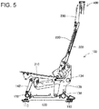
- FIGs. 3 , 4 and 5 are explanatory views illustrating an outline of the passenger seat for aircraft according to the present invention.
- the passenger seat 100 for an aircraft is attached via seat track fittings 110 fixed to the seat tracks 10 disposed on a floor of the aircraft.
- the seat track fittings 110 disposed in front of and behind the passenger seat support legs 120, and the left and right legs 120 are connected by two pipes 130 and 132.
- a reclining assembly (assembly) 200 is composed of a seat bottom frame 210 on which a passenger is to be seated, a backrest frame 220 supporting a back of the passenger, and a headrest frame 230 supporting a head portion of the passenger.
- the reclining assembly (assembly) 200 is supported reclinably by a pair of spreaders 170 that serve as a pair of frame bodies arranged on both sides of the assembly.
- the pair of spreaders 170 are coupled via a pipe 134.
- the reclining assembly (assembly) 200 includes cam followers 240 and 242 engaged with grooves 172 and 174 formed on the spreader 170, and moves in reclining motion.
- the reclining motion is driven by a direct-acting-type actuator 260.
- the actuator 260 drives a link plate 140, and moves the reclining assembly (assembly) 200 back and forth.
- the cam followers 240 and 242 move within the grooves 172 and 174 on the spreader 170, and reclines the reclining assembly (assembly) 200.
- Arms 142 and 144 are arranged on left and right sides of the link plate 140.
- FIGs. 6 , 7 and 8 illustrate steps for removing the reclining assembly (assembly) 200.
- the spreader 170 includes a rear groove 172 and a front groove 174.
- the rear groove 172 has an opening portion 173 opening upward, and the front groove 174 is opened frontward.
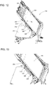
- FIGs. 9 through 11 illustrate the details of the grooves and a cover.
- the opening portion 173 of the rear groove 172 is covered by a cover 180, and the cover is fixed by a screw 190.
- the whole reclining assembly (assembly) 200 is held by hand, and the rear cam follower 240 is passed through the opening portion 173 of the groove 172 and removed upward.
- the front cam follower 242 is passed through a front opening 175 of the groove 174, and the reclining assembly (assembly) 200 is removed.
- Edge portions 173a and 173b are provided on an upper surface of the opening portion 173 of the groove 172.
- the rear edge portion 173b is designed so that a mounting surface 184 for the screw 190 of the cover 180 can be placed thereon.
- a joining portion 182 of the cover 180 engaged with the front edge portion 173a is formed to have a curved surface opening to the outer side. This configuration prevents the removed cover 180 from falling into the groove 172.
- the passenger seat 100 for an aircraft according to the present invention having the above-described configuration enables the reclining assembly (assembly) 200 to be attached to and detached from the spreader 170 easily without having to remove the spreader 170. As a result, maintenance operation can be performed efficiently.
- the passenger seat 100 for an aircraft according to the present invention can be converted into a bed mode by tilting the backrest frame 220 frontward.
- a direct-acting-type damper is provided to prevent the backrest frame 220 from tilting suddenly and to support the power to draw the back rest frame 220 up from the bed mode.
- a gas damper is used, for example, as the direct-acting-type damper.
- FIGs. 12 through 14 illustrate a direct-acting-type damper 300.
- a link frame 350 is arranged along a side frame 222 of the backrest frame 220.
- An end portion 302 of a cylinder of the direct-acting-type damper 300 is attached to the side frame 222 via a pin 330.
- An end portion 312 of a piston 310 of the direct-acting-type damper 300 is attached to the link frame 350 via the pin 330.
- the pin 330 is retained by a snap ring 340.
- FIG. 2 illustrates a state where the mechanic S is replacing the direct-acting-type damper 300.
- the mechanic cannot access the damper when the passenger seat 100 for an aircraft is positioned at an upright position, so the seat must be tilted somewhat frontward to allow access to the damper through the space between the backrest and the back shell.
- the damper cannot be visually observed directly, since there is a wall.
- the direct-acting-type damper 300 is contracted and exerts resilience. Therefore, during attachment, the direct-acting-type damper 300 must be retained in the contracted state, so it is difficult to carry out the operation in a narrow space where visual confirmation is not possible.
- a tapered portion 332 is provided at a tip of the pin 330 fixing the direct-acting-type damper 300. According to this structure, even if the mounting portion cannot be visually confirmed, or even if the direct-acting-type damper 300 is to be attached while maintaining a contracted state, the damper can be attached easily with only one hand. Therefore, the maintenance operation can be facilitated.
- the passenger seat 100 for an aircraft according to the present invention can be used in the bed mode, by tilting the backrest frame 220 and the headrest frame 230 frontward.
- an extension member 400 used during the bed mode is provided on a rear surface of the headrest frame 230.
- FIGs. 15 and 16 illustrate details of the extension member 400.
- the extension member 400 is attached pivotably to a rear surface of the headrest frame 230 by fixing an extension panel 405 using a fixed hinge 410 and a pivoting hinge 420.
- the fixed hinge 410 is fixed to a rear surface of the headrest frame 230, and one end portion of the pivoting hinge 420 is pivotably connected to the fixed hinge 410.
- the extension panel 405 is pivotably connected the other end portion of the pivoting hinge 420 via a bracket 402.
- the fixed hinge 410 is formed of an aluminum material, so as to contribute to lighter weight.
- a groove 412 is formed at a center of the fixed hinge, and a cam plate 470 is inserted thereto.
- the cam plate 470 is formed of a stainless steel or other material having a high hardness, and has a dent 472 formed thereto.
- the pivoting hinge 420 is formed of an aluminum material, and a pipe-shaped bushing 440 is inserted to an inner portion of the pivoting hinge 420.
- a spring 450 is arranged within the bushing 440, and the respective ends of the spring 450 push a ball 460.
- Each ball 460 is fit to the dent 472 of the cam plate 470, and maintains a rotation angle of the pivoting hinge 420.
- the bushing 440 and the spring 450 are formed of materials such as stainless steel and spring steel.
- a bushing 480 penetrates the cam plate 470, and a pin 430 is inserted to the bushing, which is fixed via a washer 432 and a retaining ring 434.
- the cam plate 470 can be replaced easily by pulling out the pin 430.
- the coupling portion between the pivoting hinge 420 and the bracket 402 of the extension panel can adopt a similar configuration.
- the seat according to the present invention realizes lighter weight, by only using heavy material such as steel to form portions, such as balls and springs, where abrasion occurs by action, and mainly using aluminum to form other structural members.
- the members that must be replaced when abrasion occurs are downsized, to reduce the amount of consumables. Further, the service life of the seat as a whole can be extended by considering the abrasion caused by the friction between the springs and the surrounding components, and facilitating the replacement of the bushing into which the spring is inserted.
- the passenger seat for an aircraft is configured as above, so that the replacement and maintenance of the reclining assembly and the direct-acting-type damper can be facilitated.
- the configuration and the material of components of the pivoting hinge attached to the extension member and maintaining the angle of the extension member are devised, so that the weight of the whole extension member can be reduced, and an effect is realized where maintenance such as the replacement of members can easily be performed.
Landscapes
- Engineering & Computer Science (AREA)
- Aviation & Aerospace Engineering (AREA)
- Transportation (AREA)
- Mechanical Engineering (AREA)
- Chairs For Special Purposes, Such As Reclining Chairs (AREA)
- Seats For Vehicles (AREA)
Claims (9)
- Passagiersitz (100) für ein Flugzeug, aufweisend:ein Paar Beine (120), welche über Anschlussstücke (110) an einer Sitzschiene (10) auf einer Bodenfläche des Flugzeugs befestigbar sind;zwei Rohre (130, 132), welche jeweils an einem vorderen und einem hinteren der Beine (120) befestigt sind; undein Spreizhalter (170), welcher als ein Rahmen dient, welcher an den beiden Rohren (130, 132) befestigt ist und eine Zurücklehnbaugruppe (200) des Sitzes (100) trägt,wobei die Zurücklehnbaugruppe (200) einen Sitzunterteilrahmen (210), einen Rückenlehnenrahmen (220) und einen Kopflehnenrahmen (230) aufweist, wobei der Spreizhalter (170) Nuten (172, 174), welche Steuerbolzen (240, 242) aufnehmen, welche an beiden Seiten der Zurücklehnbaugruppe (200) vorgesehen sind, und eine Abdeckung (180) aufweist, welche einen an einem oberen Abschnitt der Nut vorgesehenen Öffnungsabschnitt (173) abdeckt, welcher dafür ausgelegt ist, Montage und Demontage der Steuerbolzen (240, 242) zu ermöglichen.
- Passagiersitz (100) für ein Flugzeug nach Anspruch 1, wobei die Abdeckung (180) eine Form aufweist, welche die Abdeckung daran hindert, in die Nut zu fallen.
- Passagiersitz (100) für ein Flugzeug nach Anspruch 1, wobei die Zurücklehnbaugruppe (200) einen direkt wirkenden Dämpfer (300) aufweist, welcher an einem Seitenabschnitt des Rückenlehnenrahmens (220) angebracht ist.
- Passagiersitz (100) für ein Flugzeug nach Anspruch 3, wobei der direkt wirkende Dämpfer (300) ein Gasdämpfer ist.
- Passagiersitz (100) für ein Flugzeug nach Anspruch 3, wobei ein Stift (330), welcher den direkt wirkenden Dämpfer (300) an dem Rückenlehnenrahmen (220) befestigt, einen vorderen Endabschnitt aufweist, welcher eine konische Fläche aufweist.
- Passagiersitz (100) für ein Flugzeug nach Anspruch 1, wobei die Zurücklehnbaugruppe (200) ein Verlängerungselement (400) aufweist, welches an einem Bestückungsende des Kopflehnenrahmens (230) vorgesehen ist, und das Verlängerungselement (400) über ein drehbares Gelenk (420) an dem Kopflehnenrahmen (230) drehbar befestigt ist.
- Passagiersitz (100) für ein Flugzeug nach Anspruch 6, wobei das drehbare Gelenk (420) eine durch eine Feder (450) gedrückte Kugel (460), eine rohrförmige Hülse (440), in welche die Feder (450) eingesetzt ist, und eine Kurvenscheibenplatte (470) aufweist, welche eine die Kugel (460) aufnehmende Vertiefung aufweist.
- Passagiersitz (100) für ein Flugzeug nach Anspruch 7, wobei die Kurvenscheibenplatte (470) über einen Stift (430) befestigt ist.
- Passagiersitz (100) für ein Flugzeug nach Anspruch 7, wobei die Kugel (460), die Hülse (440) und die Kurvenscheibenplatte (470) aus einem Metall ausgebildet sind, welches eine größere Härte als das drehbare Gelenk aufweist.
Applications Claiming Priority (1)
| Application Number | Priority Date | Filing Date | Title |
|---|---|---|---|
| PCT/JP2014/072522 WO2016031003A1 (ja) | 2014-08-28 | 2014-08-28 | 航空機の乗客用シート |
Publications (3)
| Publication Number | Publication Date |
|---|---|
| EP3196121A1 EP3196121A1 (de) | 2017-07-26 |
| EP3196121A4 EP3196121A4 (de) | 2017-11-22 |
| EP3196121B1 true EP3196121B1 (de) | 2018-09-05 |
Family
ID=55398942
Family Applications (1)
| Application Number | Title | Priority Date | Filing Date |
|---|---|---|---|
| EP14900731.2A Active EP3196121B1 (de) | 2014-08-28 | 2014-08-28 | Passagiersitz für ein flugzeug |
Country Status (4)
| Country | Link |
|---|---|
| US (1) | US10093423B2 (de) |
| EP (1) | EP3196121B1 (de) |
| JP (1) | JP5890936B1 (de) |
| WO (1) | WO2016031003A1 (de) |
Families Citing this family (12)
| Publication number | Priority date | Publication date | Assignee | Title |
|---|---|---|---|---|
| EP3154818A2 (de) * | 2014-06-10 | 2017-04-19 | Zodiac Seats US LLC | Monocoque- und semimonocoque-passagiersitze mit ergonomischer gestaltung |
| CN109843641B (zh) * | 2016-09-28 | 2021-09-10 | 罗克韦尔柯林斯股份有限公司 | 包括靠背倾斜装置的飞机乘客座椅组件 |
| US10899458B2 (en) * | 2018-05-21 | 2021-01-26 | The Boeing Company | Sleep systems for aircraft |
| US11975839B2 (en) * | 2018-06-13 | 2024-05-07 | Safran Seats Usa Llc | Lightweight passenger privacy screen |
| EP3873805A1 (de) * | 2018-10-31 | 2021-09-08 | Safran Seats USA LLC | Gebogene rohrsitzstruktur |
| US10717534B2 (en) | 2018-12-17 | 2020-07-21 | Goodrich Corporation | Extendable split headrest |
| US11975842B2 (en) | 2019-09-30 | 2024-05-07 | Safran Seats Usa Llc | Bottom pan torque bearing attachment |
| DE102020106027A1 (de) * | 2020-03-05 | 2021-09-09 | Zim Flugsitz Gmbh | Fluggastsitz mit Umhausung |
| WO2021247011A1 (en) * | 2020-06-02 | 2021-12-09 | Safran Seats Santa Maria Llc | Modular channel-mounted furniture attachment |
| FR3112528B1 (fr) * | 2020-07-16 | 2022-08-12 | Safran Seats | Unite de siege munie d'une structure basse de siege de type tubulaire |
| CA3200629A1 (en) * | 2020-12-01 | 2022-06-09 | Mark Robert Hacker | Aircraft seating module |
| US11623751B2 (en) * | 2021-09-03 | 2023-04-11 | Safran Seats Usa Llc | Spreader with open slot for passenger seat |
Family Cites Families (10)
| Publication number | Priority date | Publication date | Assignee | Title |
|---|---|---|---|---|
| US4671572A (en) * | 1983-12-23 | 1987-06-09 | Erda, Inc. | Adjustable chair having roller cam adjustment mechanism |
| DE19906547B4 (de) * | 1999-02-17 | 2004-03-25 | Innovint Einrichtungs Gmbh | Kindersitz zur mobilen Verwendung in einem Flugzeug |
| US6692069B2 (en) * | 2001-07-20 | 2004-02-17 | B E Aerospace, Inc. | Aircraft sleeper seat |
| JP2004081263A (ja) | 2002-08-23 | 2004-03-18 | Aviointeriors Spa | 座席シート、特に航空機用座席シートの完全なリクライニング機能を得るための機構 |
| GB0706775D0 (en) * | 2007-04-05 | 2007-05-16 | Premium Aircraft Interiors Uk | Aircraft seat |
| JP5341991B2 (ja) * | 2008-07-08 | 2013-11-13 | ビー イー エアロスペイス,インク. | 連接式航空機シート |
| US8376458B2 (en) * | 2009-11-02 | 2013-02-19 | B/E Aerospace, Inc. | Seat pan cam follower with drop down mechanism |
| US8403415B2 (en) * | 2010-08-16 | 2013-03-26 | Be Aerospace, Inc. | Aircraft passenger seat recline mechanism |
| EP2729365B1 (de) * | 2011-07-06 | 2016-11-30 | Zodiac Seats US LLC | Sitzschalenanordnung |
| JP5827714B2 (ja) * | 2014-03-14 | 2015-12-02 | 株式会社ジャムコ | 航空機の乗客用シートのリクライニング機構 |
-
2014
- 2014-08-28 US US15/506,091 patent/US10093423B2/en active Active
- 2014-08-28 EP EP14900731.2A patent/EP3196121B1/de active Active
- 2014-08-28 WO PCT/JP2014/072522 patent/WO2016031003A1/ja active Application Filing
- 2014-08-28 JP JP2015512963A patent/JP5890936B1/ja active Active
Non-Patent Citations (1)
| Title |
|---|
| None * |
Also Published As
| Publication number | Publication date |
|---|---|
| US10093423B2 (en) | 2018-10-09 |
| WO2016031003A1 (ja) | 2016-03-03 |
| JP5890936B1 (ja) | 2016-03-22 |
| EP3196121A1 (de) | 2017-07-26 |
| US20180215469A1 (en) | 2018-08-02 |
| JPWO2016031003A1 (ja) | 2017-04-27 |
| EP3196121A4 (de) | 2017-11-22 |
Similar Documents
| Publication | Publication Date | Title |
|---|---|---|
| EP3196121B1 (de) | Passagiersitz für ein flugzeug | |
| EP2534049B1 (de) | Passagiersitz | |
| EP2983988B1 (de) | Flugzeugsitz mit übersetzendem sitzrückenlehnenverbindungsgelenk | |
| CN106114870B (zh) | 乘客座椅组件及其多个方面 | |
| CA2801760C (en) | Power actuated wall proximity furniture member | |
| EP2414233B1 (de) | Fahrgastsitz mit einem einzigen aktuatorsitzmechanismus | |
| US8366188B2 (en) | Release system for furniture member leg rest assemblies | |
| EP3060472B1 (de) | Linear ausfahrbare beinauflage eines flugzeugsitzes | |
| EP2709873B1 (de) | Kinematischer sitz mit elastischer schwingung | |
| US20110248547A1 (en) | Power actuated rocking furniture mechanism | |
| JP5827714B2 (ja) | 航空機の乗客用シートのリクライニング機構 | |
| US9061766B2 (en) | Synchronous seat recline mechanism | |
| US8714647B2 (en) | Passenger seat assembly | |
| US11305673B2 (en) | Seat and seat mounting structure | |
| EP3715255B1 (de) | Sitz, insbesondere flugzeugsitz | |
| EP3194206B1 (de) | Verstellbarer liegesitz | |
| EP4249377A1 (de) | Rücklehnmechanismus für die armlehne eines passagiersitzes | |
| US20220194280A1 (en) | Seat and seat mounting structure | |
| JP2022000366A (ja) | 荷重軽減のための滑り継ぎ手 | |
| JP3154967U (ja) | リクライニングチェア |
Legal Events
| Date | Code | Title | Description |
|---|---|---|---|
| STAA | Information on the status of an ep patent application or granted ep patent |
Free format text: STATUS: THE INTERNATIONAL PUBLICATION HAS BEEN MADE |
|
| PUAI | Public reference made under article 153(3) epc to a published international application that has entered the european phase |
Free format text: ORIGINAL CODE: 0009012 |
|
| STAA | Information on the status of an ep patent application or granted ep patent |
Free format text: STATUS: REQUEST FOR EXAMINATION WAS MADE |
|
| 17P | Request for examination filed |
Effective date: 20170222 |
|
| AK | Designated contracting states |
Kind code of ref document: A1 Designated state(s): AL AT BE BG CH CY CZ DE DK EE ES FI FR GB GR HR HU IE IS IT LI LT LU LV MC MK MT NL NO PL PT RO RS SE SI SK SM TR |
|
| AX | Request for extension of the european patent |
Extension state: BA ME |
|
| A4 | Supplementary search report drawn up and despatched |
Effective date: 20171019 |
|
| RIC1 | Information provided on ipc code assigned before grant |
Ipc: B64D 11/06 20060101AFI20171013BHEP Ipc: B60N 2/22 20060101ALI20171013BHEP |
|
| DAX | Request for extension of the european patent (deleted) | ||
| GRAP | Despatch of communication of intention to grant a patent |
Free format text: ORIGINAL CODE: EPIDOSNIGR1 |
|
| STAA | Information on the status of an ep patent application or granted ep patent |
Free format text: STATUS: GRANT OF PATENT IS INTENDED |
|
| INTG | Intention to grant announced |
Effective date: 20180313 |
|
| GRAS | Grant fee paid |
Free format text: ORIGINAL CODE: EPIDOSNIGR3 |
|
| GRAA | (expected) grant |
Free format text: ORIGINAL CODE: 0009210 |
|
| STAA | Information on the status of an ep patent application or granted ep patent |
Free format text: STATUS: THE PATENT HAS BEEN GRANTED |
|
| AK | Designated contracting states |
Kind code of ref document: B1 Designated state(s): AL AT BE BG CH CY CZ DE DK EE ES FI FR GB GR HR HU IE IS IT LI LT LU LV MC MK MT NL NO PL PT RO RS SE SI SK SM TR |
|
| REG | Reference to a national code |
Ref country code: GB Ref legal event code: FG4D |
|
| REG | Reference to a national code |
Ref country code: CH Ref legal event code: EP |
|
| REG | Reference to a national code |
Ref country code: AT Ref legal event code: REF Ref document number: 1037494 Country of ref document: AT Kind code of ref document: T Effective date: 20180915 |
|
| REG | Reference to a national code |
Ref country code: IE Ref legal event code: FG4D |
|
| REG | Reference to a national code |
Ref country code: DE Ref legal event code: R096 Ref document number: 602014032098 Country of ref document: DE |
|
| REG | Reference to a national code |
Ref country code: NL Ref legal event code: MP Effective date: 20180905 |
|
| REG | Reference to a national code |
Ref country code: LT Ref legal event code: MG4D |
|
| PG25 | Lapsed in a contracting state [announced via postgrant information from national office to epo] |
Ref country code: GR Free format text: LAPSE BECAUSE OF FAILURE TO SUBMIT A TRANSLATION OF THE DESCRIPTION OR TO PAY THE FEE WITHIN THE PRESCRIBED TIME-LIMIT Effective date: 20181206 Ref country code: NO Free format text: LAPSE BECAUSE OF FAILURE TO SUBMIT A TRANSLATION OF THE DESCRIPTION OR TO PAY THE FEE WITHIN THE PRESCRIBED TIME-LIMIT Effective date: 20181205 Ref country code: LT Free format text: LAPSE BECAUSE OF FAILURE TO SUBMIT A TRANSLATION OF THE DESCRIPTION OR TO PAY THE FEE WITHIN THE PRESCRIBED TIME-LIMIT Effective date: 20180905 Ref country code: BG Free format text: LAPSE BECAUSE OF FAILURE TO SUBMIT A TRANSLATION OF THE DESCRIPTION OR TO PAY THE FEE WITHIN THE PRESCRIBED TIME-LIMIT Effective date: 20181205 Ref country code: FI Free format text: LAPSE BECAUSE OF FAILURE TO SUBMIT A TRANSLATION OF THE DESCRIPTION OR TO PAY THE FEE WITHIN THE PRESCRIBED TIME-LIMIT Effective date: 20180905 Ref country code: RS Free format text: LAPSE BECAUSE OF FAILURE TO SUBMIT A TRANSLATION OF THE DESCRIPTION OR TO PAY THE FEE WITHIN THE PRESCRIBED TIME-LIMIT Effective date: 20180905 Ref country code: SE Free format text: LAPSE BECAUSE OF FAILURE TO SUBMIT A TRANSLATION OF THE DESCRIPTION OR TO PAY THE FEE WITHIN THE PRESCRIBED TIME-LIMIT Effective date: 20180905 |
|
| REG | Reference to a national code |
Ref country code: AT Ref legal event code: MK05 Ref document number: 1037494 Country of ref document: AT Kind code of ref document: T Effective date: 20180905 |
|
| PG25 | Lapsed in a contracting state [announced via postgrant information from national office to epo] |
Ref country code: AL Free format text: LAPSE BECAUSE OF FAILURE TO SUBMIT A TRANSLATION OF THE DESCRIPTION OR TO PAY THE FEE WITHIN THE PRESCRIBED TIME-LIMIT Effective date: 20180905 Ref country code: LV Free format text: LAPSE BECAUSE OF FAILURE TO SUBMIT A TRANSLATION OF THE DESCRIPTION OR TO PAY THE FEE WITHIN THE PRESCRIBED TIME-LIMIT Effective date: 20180905 Ref country code: HR Free format text: LAPSE BECAUSE OF FAILURE TO SUBMIT A TRANSLATION OF THE DESCRIPTION OR TO PAY THE FEE WITHIN THE PRESCRIBED TIME-LIMIT Effective date: 20180905 |
|
| PG25 | Lapsed in a contracting state [announced via postgrant information from national office to epo] |
Ref country code: EE Free format text: LAPSE BECAUSE OF FAILURE TO SUBMIT A TRANSLATION OF THE DESCRIPTION OR TO PAY THE FEE WITHIN THE PRESCRIBED TIME-LIMIT Effective date: 20180905 Ref country code: PL Free format text: LAPSE BECAUSE OF FAILURE TO SUBMIT A TRANSLATION OF THE DESCRIPTION OR TO PAY THE FEE WITHIN THE PRESCRIBED TIME-LIMIT Effective date: 20180905 Ref country code: IS Free format text: LAPSE BECAUSE OF FAILURE TO SUBMIT A TRANSLATION OF THE DESCRIPTION OR TO PAY THE FEE WITHIN THE PRESCRIBED TIME-LIMIT Effective date: 20190105 Ref country code: AT Free format text: LAPSE BECAUSE OF FAILURE TO SUBMIT A TRANSLATION OF THE DESCRIPTION OR TO PAY THE FEE WITHIN THE PRESCRIBED TIME-LIMIT Effective date: 20180905 Ref country code: RO Free format text: LAPSE BECAUSE OF FAILURE TO SUBMIT A TRANSLATION OF THE DESCRIPTION OR TO PAY THE FEE WITHIN THE PRESCRIBED TIME-LIMIT Effective date: 20180905 Ref country code: CZ Free format text: LAPSE BECAUSE OF FAILURE TO SUBMIT A TRANSLATION OF THE DESCRIPTION OR TO PAY THE FEE WITHIN THE PRESCRIBED TIME-LIMIT Effective date: 20180905 Ref country code: NL Free format text: LAPSE BECAUSE OF FAILURE TO SUBMIT A TRANSLATION OF THE DESCRIPTION OR TO PAY THE FEE WITHIN THE PRESCRIBED TIME-LIMIT Effective date: 20180905 Ref country code: ES Free format text: LAPSE BECAUSE OF FAILURE TO SUBMIT A TRANSLATION OF THE DESCRIPTION OR TO PAY THE FEE WITHIN THE PRESCRIBED TIME-LIMIT Effective date: 20180905 |
|
| PG25 | Lapsed in a contracting state [announced via postgrant information from national office to epo] |
Ref country code: SK Free format text: LAPSE BECAUSE OF FAILURE TO SUBMIT A TRANSLATION OF THE DESCRIPTION OR TO PAY THE FEE WITHIN THE PRESCRIBED TIME-LIMIT Effective date: 20180905 Ref country code: SM Free format text: LAPSE BECAUSE OF FAILURE TO SUBMIT A TRANSLATION OF THE DESCRIPTION OR TO PAY THE FEE WITHIN THE PRESCRIBED TIME-LIMIT Effective date: 20180905 Ref country code: PT Free format text: LAPSE BECAUSE OF FAILURE TO SUBMIT A TRANSLATION OF THE DESCRIPTION OR TO PAY THE FEE WITHIN THE PRESCRIBED TIME-LIMIT Effective date: 20190105 |
|
| REG | Reference to a national code |
Ref country code: DE Ref legal event code: R097 Ref document number: 602014032098 Country of ref document: DE |
|
| PLBE | No opposition filed within time limit |
Free format text: ORIGINAL CODE: 0009261 |
|
| STAA | Information on the status of an ep patent application or granted ep patent |
Free format text: STATUS: NO OPPOSITION FILED WITHIN TIME LIMIT |
|
| PG25 | Lapsed in a contracting state [announced via postgrant information from national office to epo] |
Ref country code: DK Free format text: LAPSE BECAUSE OF FAILURE TO SUBMIT A TRANSLATION OF THE DESCRIPTION OR TO PAY THE FEE WITHIN THE PRESCRIBED TIME-LIMIT Effective date: 20180905 |
|
| 26N | No opposition filed |
Effective date: 20190606 |
|
| PG25 | Lapsed in a contracting state [announced via postgrant information from national office to epo] |
Ref country code: SI Free format text: LAPSE BECAUSE OF FAILURE TO SUBMIT A TRANSLATION OF THE DESCRIPTION OR TO PAY THE FEE WITHIN THE PRESCRIBED TIME-LIMIT Effective date: 20180905 |
|
| PG25 | Lapsed in a contracting state [announced via postgrant information from national office to epo] |
Ref country code: TR Free format text: LAPSE BECAUSE OF FAILURE TO SUBMIT A TRANSLATION OF THE DESCRIPTION OR TO PAY THE FEE WITHIN THE PRESCRIBED TIME-LIMIT Effective date: 20180905 |
|
| PG25 | Lapsed in a contracting state [announced via postgrant information from national office to epo] |
Ref country code: LU Free format text: LAPSE BECAUSE OF NON-PAYMENT OF DUE FEES Effective date: 20190828 Ref country code: LI Free format text: LAPSE BECAUSE OF NON-PAYMENT OF DUE FEES Effective date: 20190831 Ref country code: CH Free format text: LAPSE BECAUSE OF NON-PAYMENT OF DUE FEES Effective date: 20190831 Ref country code: MC Free format text: LAPSE BECAUSE OF FAILURE TO SUBMIT A TRANSLATION OF THE DESCRIPTION OR TO PAY THE FEE WITHIN THE PRESCRIBED TIME-LIMIT Effective date: 20180905 |
|
| REG | Reference to a national code |
Ref country code: BE Ref legal event code: MM Effective date: 20190831 |
|
| PG25 | Lapsed in a contracting state [announced via postgrant information from national office to epo] |
Ref country code: IE Free format text: LAPSE BECAUSE OF NON-PAYMENT OF DUE FEES Effective date: 20190828 |
|
| PG25 | Lapsed in a contracting state [announced via postgrant information from national office to epo] |
Ref country code: BE Free format text: LAPSE BECAUSE OF NON-PAYMENT OF DUE FEES Effective date: 20190831 |
|
| PG25 | Lapsed in a contracting state [announced via postgrant information from national office to epo] |
Ref country code: CY Free format text: LAPSE BECAUSE OF FAILURE TO SUBMIT A TRANSLATION OF THE DESCRIPTION OR TO PAY THE FEE WITHIN THE PRESCRIBED TIME-LIMIT Effective date: 20180905 |
|
| PG25 | Lapsed in a contracting state [announced via postgrant information from national office to epo] |
Ref country code: MT Free format text: LAPSE BECAUSE OF FAILURE TO SUBMIT A TRANSLATION OF THE DESCRIPTION OR TO PAY THE FEE WITHIN THE PRESCRIBED TIME-LIMIT Effective date: 20180905 Ref country code: HU Free format text: LAPSE BECAUSE OF FAILURE TO SUBMIT A TRANSLATION OF THE DESCRIPTION OR TO PAY THE FEE WITHIN THE PRESCRIBED TIME-LIMIT; INVALID AB INITIO Effective date: 20140828 |
|
| PG25 | Lapsed in a contracting state [announced via postgrant information from national office to epo] |
Ref country code: MK Free format text: LAPSE BECAUSE OF FAILURE TO SUBMIT A TRANSLATION OF THE DESCRIPTION OR TO PAY THE FEE WITHIN THE PRESCRIBED TIME-LIMIT Effective date: 20180905 |
|
| P01 | Opt-out of the competence of the unified patent court (upc) registered |
Effective date: 20230527 |
|
| PGFP | Annual fee paid to national office [announced via postgrant information from national office to epo] |
Ref country code: IT Payment date: 20230711 Year of fee payment: 10 Ref country code: GB Payment date: 20230706 Year of fee payment: 10 |
|
| PGFP | Annual fee paid to national office [announced via postgrant information from national office to epo] |
Ref country code: FR Payment date: 20230703 Year of fee payment: 10 Ref country code: DE Payment date: 20230703 Year of fee payment: 10 |