EP3195967A1 - Drill - Google Patents
Drill Download PDFInfo
- Publication number
- EP3195967A1 EP3195967A1 EP15841373.2A EP15841373A EP3195967A1 EP 3195967 A1 EP3195967 A1 EP 3195967A1 EP 15841373 A EP15841373 A EP 15841373A EP 3195967 A1 EP3195967 A1 EP 3195967A1
- Authority
- EP
- European Patent Office
- Prior art keywords
- ridge line
- face
- curvature radius
- intersecting position
- drill
- Prior art date
- Legal status (The legal status is an assumption and is not a legal conclusion. Google has not performed a legal analysis and makes no representation as to the accuracy of the status listed.)
- Granted
Links
Images

Classifications
-
- B—PERFORMING OPERATIONS; TRANSPORTING
- B23—MACHINE TOOLS; METAL-WORKING NOT OTHERWISE PROVIDED FOR
- B23B—TURNING; BORING
- B23B51/00—Tools for drilling machines
- B23B51/02—Twist drills
-
- C—CHEMISTRY; METALLURGY
- C23—COATING METALLIC MATERIAL; COATING MATERIAL WITH METALLIC MATERIAL; CHEMICAL SURFACE TREATMENT; DIFFUSION TREATMENT OF METALLIC MATERIAL; COATING BY VACUUM EVAPORATION, BY SPUTTERING, BY ION IMPLANTATION OR BY CHEMICAL VAPOUR DEPOSITION, IN GENERAL; INHIBITING CORROSION OF METALLIC MATERIAL OR INCRUSTATION IN GENERAL
- C23C—COATING METALLIC MATERIAL; COATING MATERIAL WITH METALLIC MATERIAL; SURFACE TREATMENT OF METALLIC MATERIAL BY DIFFUSION INTO THE SURFACE, BY CHEMICAL CONVERSION OR SUBSTITUTION; COATING BY VACUUM EVAPORATION, BY SPUTTERING, BY ION IMPLANTATION OR BY CHEMICAL VAPOUR DEPOSITION, IN GENERAL
- C23C14/00—Coating by vacuum evaporation, by sputtering or by ion implantation of the coating forming material
- C23C14/04—Coating on selected surface areas, e.g. using masks
-
- C—CHEMISTRY; METALLURGY
- C23—COATING METALLIC MATERIAL; COATING MATERIAL WITH METALLIC MATERIAL; CHEMICAL SURFACE TREATMENT; DIFFUSION TREATMENT OF METALLIC MATERIAL; COATING BY VACUUM EVAPORATION, BY SPUTTERING, BY ION IMPLANTATION OR BY CHEMICAL VAPOUR DEPOSITION, IN GENERAL; INHIBITING CORROSION OF METALLIC MATERIAL OR INCRUSTATION IN GENERAL
- C23C—COATING METALLIC MATERIAL; COATING MATERIAL WITH METALLIC MATERIAL; SURFACE TREATMENT OF METALLIC MATERIAL BY DIFFUSION INTO THE SURFACE, BY CHEMICAL CONVERSION OR SUBSTITUTION; COATING BY VACUUM EVAPORATION, BY SPUTTERING, BY ION IMPLANTATION OR BY CHEMICAL VAPOUR DEPOSITION, IN GENERAL
- C23C14/00—Coating by vacuum evaporation, by sputtering or by ion implantation of the coating forming material
- C23C14/06—Coating by vacuum evaporation, by sputtering or by ion implantation of the coating forming material characterised by the coating material
-
- B—PERFORMING OPERATIONS; TRANSPORTING
- B23—MACHINE TOOLS; METAL-WORKING NOT OTHERWISE PROVIDED FOR
- B23B—TURNING; BORING
- B23B2224/00—Materials of tools or workpieces composed of a compound including a metal
- B23B2224/24—Titanium aluminium nitride
-
- B—PERFORMING OPERATIONS; TRANSPORTING
- B23—MACHINE TOOLS; METAL-WORKING NOT OTHERWISE PROVIDED FOR
- B23B—TURNING; BORING
- B23B2228/00—Properties of materials of tools or workpieces, materials of tools or workpieces applied in a specific manner
- B23B2228/08—Properties of materials of tools or workpieces, materials of tools or workpieces applied in a specific manner applied by physical vapour deposition [PVD]
-
- B—PERFORMING OPERATIONS; TRANSPORTING
- B23—MACHINE TOOLS; METAL-WORKING NOT OTHERWISE PROVIDED FOR
- B23B—TURNING; BORING
- B23B2228/00—Properties of materials of tools or workpieces, materials of tools or workpieces applied in a specific manner
- B23B2228/10—Coatings
-
- B—PERFORMING OPERATIONS; TRANSPORTING
- B23—MACHINE TOOLS; METAL-WORKING NOT OTHERWISE PROVIDED FOR
- B23B—TURNING; BORING
- B23B2251/00—Details of tools for drilling machines
- B23B2251/08—Side or plan views of cutting edges
- B23B2251/082—Curved cutting edges
-
- B—PERFORMING OPERATIONS; TRANSPORTING
- B23—MACHINE TOOLS; METAL-WORKING NOT OTHERWISE PROVIDED FOR
- B23B—TURNING; BORING
- B23B2251/00—Details of tools for drilling machines
- B23B2251/12—Cross sectional views of the cutting edges
- B23B2251/122—Bevelled cutting edges
-
- B—PERFORMING OPERATIONS; TRANSPORTING
- B23—MACHINE TOOLS; METAL-WORKING NOT OTHERWISE PROVIDED FOR
- B23B—TURNING; BORING
- B23B2251/00—Details of tools for drilling machines
- B23B2251/12—Cross sectional views of the cutting edges
- B23B2251/125—Rounded cutting edges
-
- B—PERFORMING OPERATIONS; TRANSPORTING
- B23—MACHINE TOOLS; METAL-WORKING NOT OTHERWISE PROVIDED FOR
- B23B—TURNING; BORING
- B23B2251/00—Details of tools for drilling machines
- B23B2251/14—Configuration of the cutting part, i.e. the main cutting edges
-
- B—PERFORMING OPERATIONS; TRANSPORTING
- B23—MACHINE TOOLS; METAL-WORKING NOT OTHERWISE PROVIDED FOR
- B23B—TURNING; BORING
- B23B2251/00—Details of tools for drilling machines
- B23B2251/40—Flutes, i.e. chip conveying grooves
- B23B2251/408—Spiral grooves
-
- B—PERFORMING OPERATIONS; TRANSPORTING
- B23—MACHINE TOOLS; METAL-WORKING NOT OTHERWISE PROVIDED FOR
- B23B—TURNING; BORING
- B23B2251/00—Details of tools for drilling machines
- B23B2251/44—Margins, i.e. the narrow portion of the land which is not cut away to provide clearance on the circumferential surface
-
- C—CHEMISTRY; METALLURGY
- C23—COATING METALLIC MATERIAL; COATING MATERIAL WITH METALLIC MATERIAL; CHEMICAL SURFACE TREATMENT; DIFFUSION TREATMENT OF METALLIC MATERIAL; COATING BY VACUUM EVAPORATION, BY SPUTTERING, BY ION IMPLANTATION OR BY CHEMICAL VAPOUR DEPOSITION, IN GENERAL; INHIBITING CORROSION OF METALLIC MATERIAL OR INCRUSTATION IN GENERAL
- C23C—COATING METALLIC MATERIAL; COATING MATERIAL WITH METALLIC MATERIAL; SURFACE TREATMENT OF METALLIC MATERIAL BY DIFFUSION INTO THE SURFACE, BY CHEMICAL CONVERSION OR SUBSTITUTION; COATING BY VACUUM EVAPORATION, BY SPUTTERING, BY ION IMPLANTATION OR BY CHEMICAL VAPOUR DEPOSITION, IN GENERAL
- C23C14/00—Coating by vacuum evaporation, by sputtering or by ion implantation of the coating forming material
- C23C14/22—Coating by vacuum evaporation, by sputtering or by ion implantation of the coating forming material characterised by the process of coating
- C23C14/228—Gas flow assisted PVD deposition
-
- Y—GENERAL TAGGING OF NEW TECHNOLOGICAL DEVELOPMENTS; GENERAL TAGGING OF CROSS-SECTIONAL TECHNOLOGIES SPANNING OVER SEVERAL SECTIONS OF THE IPC; TECHNICAL SUBJECTS COVERED BY FORMER USPC CROSS-REFERENCE ART COLLECTIONS [XRACs] AND DIGESTS
- Y10—TECHNICAL SUBJECTS COVERED BY FORMER USPC
- Y10T—TECHNICAL SUBJECTS COVERED BY FORMER US CLASSIFICATION
- Y10T408/00—Cutting by use of rotating axially moving tool
- Y10T408/89—Tool or Tool with support
- Y10T408/905—Having stepped cutting edges
- Y10T408/906—Axially spaced
-
- Y—GENERAL TAGGING OF NEW TECHNOLOGICAL DEVELOPMENTS; GENERAL TAGGING OF CROSS-SECTIONAL TECHNOLOGIES SPANNING OVER SEVERAL SECTIONS OF THE IPC; TECHNICAL SUBJECTS COVERED BY FORMER USPC CROSS-REFERENCE ART COLLECTIONS [XRACs] AND DIGESTS
- Y10—TECHNICAL SUBJECTS COVERED BY FORMER USPC
- Y10T—TECHNICAL SUBJECTS COVERED BY FORMER US CLASSIFICATION
- Y10T408/00—Cutting by use of rotating axially moving tool
- Y10T408/89—Tool or Tool with support
- Y10T408/909—Having peripherally spaced cutting edges
- Y10T408/9095—Having peripherally spaced cutting edges with axially extending relief channel
- Y10T408/9097—Spiral channel
Definitions
- the present invention relates to a drill whose life is extended by devising edge tip treatment.
- Drills especially, a drill formed of cemented carbide that is more brittle than highspeed steel is subjected to edge tip treatment to reinforce a cutting edge for longer life.
- the cutting edge can be reinforced by removing a sharp portion of the edge tip, for example by chamfering or honing.
- a cutting edge of a twist drill is chamfered to be a combination of a straight face and a curved face or to be a curved face.
- the curved part of the chamfered portion is mirror-finished or satin-finished to suppress floating of hard particles on the surface of the curved part.
- the edge tip is generally reinforced by cutting a rake face and a flank face along the cutting edge to dull the edge tip. In such treatment, however, it is difficult to suppress damage to an outer peripheral portion of the cutting edge.
- chipping resistance is insufficient in the outermost peripheral portion of the cutting edge where the cutting speed is the highest, particularly at ridge lines at an intersecting position of the flank face and the chamfered face and at an intersecting position of the flank face and a margin.
- An object of the present invention is to make the life of a drill longer than the life of a conventional drill subjected to general edge tip treatment by suppressing wear and damage in an outer peripheral portion of a cutting edge of the drill.
- a negative land for edge tip reinforcement is provided on a rake face, and a ridge line at an intersecting position of the negative land and a flank face, a ridge line at an intersecting position of the flank face and a margin, and a ridge line at an intersecting position of the negative land and the margin are convex faces in a longitudinal rectangular cross section.
- a curvature radius of the convex face of a first ridge line at the intersecting position of the flank face and the negative land is 1
- a curvature radius of the convex face of a second ridge line at the intersecting position of the flank face and the margin is 0.8 to 1.5 times the curvature radius of the first ridge line
- a curvature radius of the convex face of a fourth ridge line at the intersecting position of the negative land and the margin is 1.5 to 3.0 times the curvature radius of the first ridge line.
- fine chipping rarely occurs in an outer peripheral portion of a cutting edge, and early wear triggered by fine chipping is suppressed. This greatly extends the life.
- a negative land for edge tip reinforcement is provided on a rake face.
- a ridge line at an intersecting position of the negative land and a flank face, a ridge line at an intersecting position of the flank face and a margin, and a ridge line at an intersecting position of the negative land and the margin are convex faces in a longitudinal rectangular cross section.
- a curvature radius of the convex face of a first ridge line at the intersecting position of the flank face and the negative land is 1
- a curvature radius of the convex face of a second ridge line at the intersecting position of the flank face and the margin is 0.8 to 1.5 times the curvature radius of the first ridge line
- a curvature radius of the convex face of a fourth ridge line at the intersecting position of the negative land and the margin is 1.5 to 3.0 times the curvature radius of the first ridge line.
- the ridge line at the intersecting position of the negative land and the flank face, the ridge line at the intersecting position of the flank face and the margin, and the ridge line at the intersecting position of the negative land and the margin are formed by convex faces, and when the curvature radius of the convex face of the first ridge line at the intersecting position of the flank face and the negative land is 1, the curvature radius of the convex face of the second ridge line at the intersecting position of the flank face and the margin is 0.8 to 1.5 times the curvature radius of the first ridge, and the curvature radius of the convex face of the fourth ridge line at the intersecting position of the negative land and the margin is 1.5 to 3.0 times the curvature radius of the first ridge line.
- fine chipping rarely occurs in an outer peripheral portion of a cutting edge, and early wear triggered by fine chipping is suppressed. This greatly extends the life.
- An illustrated drill 1 is a two-flute twist drill.
- a flute face near a distal end of a helical flute 3 provided on an outer periphery of a body part 2 serves as a rake face 4.
- a cutting edge 6 is formed by a ridge line at an intersecting position of the rake face 4 and a distal flank face 5 and a ridge line at an intersecting position of the flank face 5 and a groove face of a web thinning portion 7 provided at the center of the distal end of the body part 2.
- Reference numerals 8 and 9 denote a margin and a shank continuing rearward from the body part 2, respectively.
- the drill 1 has a negative land 10 for edge tip reinforcement on the rake face 4.
- the negative land 10 provided in the illustrated drill is inclined by a predetermined angle ⁇ in a negative direction (a direction opposite from the helical direction of the helical flute 3) with respect to the axis of the drill.
- the angle ⁇ is set at about -15° to -35° with consideration for the balance between sharpness of the cutting edge and edge tip reinforcement.
- a width w of the negative land 10 when viewed from a direction perpendicular to the axis is set at about 0.03 to 0.15 mm.
- a region of the margin 8 shown by a one-dot chain line in Figs. 2 and 6 is removed. As illustrated in Fig. 6 , a corner C at which three faces of the negative land 10, the flank face 5, and the margin 8 intersect is formed at the most distal end portion of the margin 8.
- the present invention was made by examining the measures to effectively suppress wear and damage in the outer peripheral portion of the cutting edge. As a result, it was found to be effective to form a first ridge line RL1, a second ridge line RL2, and a fourth ridge line RL4 at intersecting positions of three faces of the flank face 5, the margin 8, and the negative land 10 in the shape of convex faces in a longitudinal rectangular cross section. These ridge lines are rounded to be convex faces.
- the first ridge line RL1 is a ridge line at the intersecting position of the flank face 5 and the negative land 10
- the second ridge line RL2 is a ridge line at the intersecting position of the flank face 5 and the margin 8
- the fourth ridge line RL4 is a ridge line at the intersecting position of the negative land 10 and the margin 8.
- a third ridge line RL3 at an intersecting position of the rake face 4 and the margin 8 and a fifth ridge line RL5 at an intersecting position of the negative land 10 and the rake face 4 may also be subjected to rounding similarly to the first ridge line RL1, the second ridge line RL2, and the fourth ridge line RL4.
- the fifth ridge line RL5 is also reinforced by rounding.
- the curvature radii of the convex faces of the first to fourth ridge lines RL1 to RL4 in the longitudinal rectangular cross section are preferably 0.01 mm or more.
- a so-called film skipping phenomenon (a portion in which a film is not deposited is formed) can be suppressed and the ridge lines can also be properly coated when the present invention is applied to a coating drill whose surface is provided with a highly wear-resistant hard coating of, for example, TiAl.
- the curvature radii of the convex faces of the ridge lines are given as the ratios to the curvature radius of the first ridge line RL1 when the curvature radius is 1. It was good that the curvature radii of the second ridge line RL2 and the third ridge line RL3 were 0.8 to 1.5 times the curvature radius of the first ridge line RL1 and the curvature radius of the fourth ridge line RL4 was 1.5 to 3.0 times the curvature radius of the first ridge line RL1.
- An adequate curvature radius of the first ridge line RL1 was 0.015 to 0.035 mm.
- a more preferable curvature radius of the first ridge line RL1 was 0.021 to 0.035 mm. In this range, fine chipping rarely occurs in the outer peripheral portion of the cutting edge, and early wear triggered by fine chipping is suppressed. This greatly extends the life.
- the curvature radius on the outer peripheral side was preferably larger than the curvature radius on the rotation center side. By making the curvature radius on the rotation center side to be smaller, reduction in sharpness of the cutting edge can be suppressed. By setting the curvature radius on the outer peripheral side to be larger, the reinforcing effect for the corner C can be enhanced.
- a preferable curvature radius of the second ridge line RL2 was 0.020 to 0.040 mm, and a preferable curvature radius of the fourth ridge line RL4 was 0.040 to 0.075 mm. In these ranges, fine chipping rarely occurs in the outer peripheral portion of the cutting edge, and early wear triggered by fine chipping is suppressed. This greatly extends the life. Examples
- a two-flute twist drill formed of cemented carbide and having the shape illustrated in Figs. 1 to 5 was prototyped.
- a diameter D was 8 mm, and a ratio L/D of an effective edge length L and the diameter D was 5.
- a rake face along the cutting edge is provided with a negative land having an inclination angle ⁇ of -25° and a width w of 0.07 mm when viewed from a direction perpendicular to the axis.
- Ridge lines (first ridge line RL1, second ridge line RL2, fourth ridge line RL4) between the negative land and a flank face, between the negative land and a margin, and between the flank face and the margin are rounded to be convex faces in a longitudinal rectangular cross section.
- ridge lines were rounded by inserting a distal end of the drill in polishing media powder and revolving and moving the drill in the direction perpendicular to the axis. For this reason, a third ridge line RL3 and a fifth ridge line RL5 are also rounded convex faces in a longitudinal rectangular cross section.
- the curvature radius of the first ridge line RL1 is about 0.025 mm
- the curvature radius of the second ridge line RL2 is about 0.03 mm
- the curvature radius of the fourth ridge line RL4 is about 0.060 mm.
- a coating film of TiAl was formed by PVD after reinforcing treatment of the edge tip.
- the comparative drill was markedly worn in a hatched region of Fig. 8 , that is, in regions near a corner of a first ridge line RL1, a second ridge line RL2, and a fourth ridge line RL4 and a region along the first ridge line RL1.
- the worn parts of the prototyped drill are slightly distant from the tip of the corner C. This is because the corner C was also rounded by rounding three ridge lines of the first ridge line RL1, the second ridge line RL2, and the fourth ridge line RL4 and the contact point of an outer end portion of the cutting edge with the workpiece retreated.
- the worn parts are less likely to be chipped than the tip of the corner.
- the spread of fine chipping is s, and the wear speed of the corner at which three faces of the negative land, the flank face, and the margin intersect is lower than in the conventional drill.
- the drills used in the performance evaluation test are each a two-flute coating twist drill having a hard coating on its surface
- the present invention is also applied to, for example, a drill having no hard coating, a drill having three or more flutes, and a straight drill in which a chip evacuation groove is not twisted.
Landscapes
- Chemical & Material Sciences (AREA)
- Engineering & Computer Science (AREA)
- Mechanical Engineering (AREA)
- Chemical Kinetics & Catalysis (AREA)
- Materials Engineering (AREA)
- Metallurgy (AREA)
- Organic Chemistry (AREA)
- Drilling Tools (AREA)
Description
- The present invention relates to a drill whose life is extended by devising edge tip treatment.
- Drills, especially, a drill formed of cemented carbide that is more brittle than highspeed steel is subjected to edge tip treatment to reinforce a cutting edge for longer life.
- The cutting edge can be reinforced by removing a sharp portion of the edge tip, for example by chamfering or honing.
- In edge tip treatment for reinforcement described in, for example,
PTL 1 below, a cutting edge of a twist drill is chamfered to be a combination of a straight face and a curved face or to be a curved face. The curved part of the chamfered portion is mirror-finished or satin-finished to suppress floating of hard particles on the surface of the curved part. - PTL 1: Japanese Unexamined Patent Application Publication No.
2000-52121 - As described in
PTL 1, the edge tip is generally reinforced by cutting a rake face and a flank face along the cutting edge to dull the edge tip. In such treatment, however, it is difficult to suppress damage to an outer peripheral portion of the cutting edge. - In the conventional typical edge tip treatment, chipping resistance is insufficient in the outermost peripheral portion of the cutting edge where the cutting speed is the highest, particularly at ridge lines at an intersecting position of the flank face and the chamfered face and at an intersecting position of the flank face and a margin.
- For this reason, fine chipping is caused in the outer peripheral portion of the cutting edge by repetition of microvibrations during treatment. This triggers progress of wear and damage.
- An object of the present invention is to make the life of a drill longer than the life of a conventional drill subjected to general edge tip treatment by suppressing wear and damage in an outer peripheral portion of a cutting edge of the drill.
- In a drill according to a mode of the present invention that is provided as a solution to the above-described problem, a negative land for edge tip reinforcement is provided on a rake face, and a ridge line at an intersecting position of the negative land and a flank face, a ridge line at an intersecting position of the flank face and a margin, and a ridge line at an intersecting position of the negative land and the margin are convex faces in a longitudinal rectangular cross section. When a curvature radius of the convex face of a first ridge line at the intersecting position of the flank face and the negative land is 1, a curvature radius of the convex face of a second ridge line at the intersecting position of the flank face and the margin is 0.8 to 1.5 times the curvature radius of the first ridge line, and a curvature radius of the convex face of a fourth ridge line at the intersecting position of the negative land and the margin is 1.5 to 3.0 times the curvature radius of the first ridge line.
- In the drill according to the mode of the present invention, fine chipping rarely occurs in an outer peripheral portion of a cutting edge, and early wear triggered by fine chipping is suppressed. This greatly extends the life.
-
- [
Fig. 1] Figure 1 is a side view of an example of a drill according to an embodiment of the present invention. - [
Fig. 2] Figure 2 is an enlarged side view of an outer end portion of a cutting edge as viewed from a direction of arrow A ofFig. 1 . - [
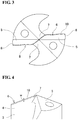
Fig. 3] Figure 3 is a front view of the drill ofFig. 1 . - [
Fig. 4] Figure 4 is an enlarged side view of a part ofFig. 1 . - [
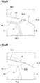
Fig. 5] Figure 5 is an enlarged perspective view of a corner part in the outer end portion of the cutting edge. - [
Fig. 6] Figure 6 is a perspective view illustrating a state before ridge lines between faces in the corner part ofFig. 5 are rounded. - [
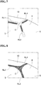
Fig. 7] Figure 7 is a perspective view illustrating a wear state of a corner part of an outer end portion of a cutting edge in a prototyped drill used in an evaluation test. - [
Fig. 8] Figure 8 is a perspective view illustrating a wear state of a corner part of an outer end portion of a cutting edge in a comparative drill used in the evaluation test. Description of Embodiments - In a drill according to an embodiment of the present invention, a negative land for edge tip reinforcement is provided on a rake face. A ridge line at an intersecting position of the negative land and a flank face, a ridge line at an intersecting position of the flank face and a margin, and a ridge line at an intersecting position of the negative land and the margin are convex faces in a longitudinal rectangular cross section. When a curvature radius of the convex face of a first ridge line at the intersecting position of the flank face and the negative land is 1, a curvature radius of the convex face of a second ridge line at the intersecting position of the flank face and the margin is 0.8 to 1.5 times the curvature radius of the first ridge line, and a curvature radius of the convex face of a fourth ridge line at the intersecting position of the negative land and the margin is 1.5 to 3.0 times the curvature radius of the first ridge line.
- In this way, the ridge line at the intersecting position of the negative land and the flank face, the ridge line at the intersecting position of the flank face and the margin, and the ridge line at the intersecting position of the negative land and the margin are formed by convex faces, and when the curvature radius of the convex face of the first ridge line at the intersecting position of the flank face and the negative land is 1, the curvature radius of the convex face of the second ridge line at the intersecting position of the flank face and the margin is 0.8 to 1.5 times the curvature radius of the first ridge, and the curvature radius of the convex face of the fourth ridge line at the intersecting position of the negative land and the margin is 1.5 to 3.0 times the curvature radius of the first ridge line. In such a drill, fine chipping rarely occurs in an outer peripheral portion of a cutting edge, and early wear triggered by fine chipping is suppressed. This greatly extends the life.
- A specific example of a drill according to an embodiment of the present invention will be described below with reference to the attached drawings of
Figs. 1 to 5 . It should be noted that the present invention is limited to these illustrations. The scope of the present invention is defined by the claims, and it is intended to include all modifications within the scope of the claims and the equivalents thereof. - An illustrated
drill 1 is a two-flute twist drill. A flute face near a distal end of ahelical flute 3 provided on an outer periphery of abody part 2 serves as arake face 4. - A
cutting edge 6 is formed by a ridge line at an intersecting position of therake face 4 and adistal flank face 5 and a ridge line at an intersecting position of theflank face 5 and a groove face of aweb thinning portion 7 provided at the center of the distal end of thebody part 2.Reference numerals body part 2, respectively. - The
drill 1 has anegative land 10 for edge tip reinforcement on therake face 4.
As illustrated inFig. 2 , thenegative land 10 provided in the illustrated drill is inclined by a predetermined angle α in a negative direction (a direction opposite from the helical direction of the helical flute 3) with respect to the axis of the drill. - The angle α is set at about -15° to -35° with consideration for the balance between sharpness of the cutting edge and edge tip reinforcement.
- A width w of the
negative land 10 when viewed from a direction perpendicular to the axis (seeFig. 4 ) is set at about 0.03 to 0.15 mm. By selecting this numerical range, the edge tip can be reinforced while ensuring sharpness. - By forming the
negative land 10 on the rake face, a region of themargin 8 shown by a one-dot chain line inFigs. 2 and6 is removed. As illustrated inFig. 6 , a corner C at which three faces of thenegative land 10, theflank face 5, and themargin 8 intersect is formed at the most distal end portion of themargin 8. - In conventional edge tip treatment, it seems that wear of the outer peripheral portion of the cutting edge is accelerated by reduction in sharpness because a tip of the corner C is easily chipped, fine chipping starts from the tip, and a damaged portion spreads.
- The present invention was made by examining the measures to effectively suppress wear and damage in the outer peripheral portion of the cutting edge. As a result, it was found to be effective to form a first ridge line RL1, a second ridge line RL2, and a fourth ridge line RL4 at intersecting positions of three faces of the
flank face 5, themargin 8, and thenegative land 10 in the shape of convex faces in a longitudinal rectangular cross section. These ridge lines are rounded to be convex faces. - The first ridge line RL1 is a ridge line at the intersecting position of the
flank face 5 and thenegative land 10, the second ridge line RL2 is a ridge line at the intersecting position of theflank face 5 and themargin 8, and the fourth ridge line RL4 is a ridge line at the intersecting position of thenegative land 10 and themargin 8. - A third ridge line RL3 at an intersecting position of the
rake face 4 and themargin 8 and a fifth ridge line RL5 at an intersecting position of thenegative land 10 and therake face 4 may also be subjected to rounding similarly to the first ridge line RL1, the second ridge line RL2, and the fourth ridge line RL4. The fifth ridge line RL5 is also reinforced by rounding. - The curvature radii of the convex faces of the first to fourth ridge lines RL1 to RL4 in the longitudinal rectangular cross section are preferably 0.01 mm or more. By setting the curvature radii at 0.01 mm or more, a so-called film skipping phenomenon (a portion in which a film is not deposited is formed) can be suppressed and the ridge lines can also be properly coated when the present invention is applied to a coating drill whose surface is provided with a highly wear-resistant hard coating of, for example, TiAl.
- The curvature radii of the convex faces of the ridge lines are given as the ratios to the curvature radius of the first ridge line RL1 when the curvature radius is 1. It was good that the curvature radii of the second ridge line RL2 and the third ridge line RL3 were 0.8 to 1.5 times the curvature radius of the first ridge line RL1 and the curvature radius of the fourth ridge line RL4 was 1.5 to 3.0 times the curvature radius of the first ridge line RL1.
- An adequate curvature radius of the first ridge line RL1 was 0.015 to 0.035 mm. A more preferable curvature radius of the first ridge line RL1 was 0.021 to 0.035 mm. In this range, fine chipping rarely occurs in the outer peripheral portion of the cutting edge, and early wear triggered by fine chipping is suppressed. This greatly extends the life. In the first ridge line RL1, the curvature radius on the outer peripheral side was preferably larger than the curvature radius on the rotation center side. By making the curvature radius on the rotation center side to be smaller, reduction in sharpness of the cutting edge can be suppressed. By setting the curvature radius on the outer peripheral side to be larger, the reinforcing effect for the corner C can be enhanced.
- A preferable curvature radius of the second ridge line RL2 was 0.020 to 0.040 mm, and a preferable curvature radius of the fourth ridge line RL4 was 0.040 to 0.075 mm. In these ranges, fine chipping rarely occurs in the outer peripheral portion of the cutting edge, and early wear triggered by fine chipping is suppressed. This greatly extends the life. Examples
- A two-flute twist drill formed of cemented carbide and having the shape illustrated in
Figs. 1 to 5 was prototyped. A diameter D was 8 mm, and a ratio L/D of an effective edge length L and the diameter D was 5. In the prototyped drill, a rake face along the cutting edge is provided with a negative land having an inclination angle α of -25° and a width w of 0.07 mm when viewed from a direction perpendicular to the axis. - Ridge lines (first ridge line RL1, second ridge line RL2, fourth ridge line RL4) between the negative land and a flank face, between the negative land and a margin, and between the flank face and the margin are rounded to be convex faces in a longitudinal rectangular cross section.
- The ridge lines were rounded by inserting a distal end of the drill in polishing media powder and revolving and moving the drill in the direction perpendicular to the axis. For this reason, a third ridge line RL3 and a fifth ridge line RL5 are also rounded convex faces in a longitudinal rectangular cross section.
- As the curvature radii of the convex faces of the first ridge line RL1, the second ridge line RL2, and the fourth ridge line RL4, the curvature radius of the first ridge line RL1 is about 0.025 mm, the curvature radius of the second ridge line RL2 is about 0.03 mm, and the curvature radius of the fourth ridge line RL4 is about 0.060 mm.
- On a surface of the drill, a coating film of TiAl was formed by PVD after reinforcing treatment of the edge tip.
- Workpieces were bored under the following conditions by using this prototyped drill and a comparative drill in which a negative land similar to that of the prototyped drill was formed on a rake face and a ridge line between the negative land and a flank face was rounded by honing (the comparative drill was different only in the treatment method for the ridge line from the prototyped drill).
-
- Workpiece: S50C (HB230)
- Cutting speed Vc = 80 m/min
- Feed f = 0.25 mm/rev
- Machined hole depth H = 38 mm
- Total cutting length: 36 m
- As a result of this test, the comparative drill was markedly worn in a hatched region of
Fig. 8 , that is, in regions near a corner of a first ridge line RL1, a second ridge line RL2, and a fourth ridge line RL4 and a region along the first ridge line RL1. - In contrast, as illustrated in
Fig. 7 , in the prototyped drill, parts of the rounded first ridge line RL1, second ridge line RL2, and fourth ridge line RL4 were just slightly worn. - The worn parts of the prototyped drill are slightly distant from the tip of the corner C. This is because the corner C was also rounded by rounding three ridge lines of the first ridge line RL1, the second ridge line RL2, and the fourth ridge line RL4 and the contact point of an outer end portion of the cutting edge with the workpiece retreated.
- The worn parts are less likely to be chipped than the tip of the corner. Thus, the spread of fine chipping is s, and the wear speed of the corner at which three faces of the negative land, the flank face, and the margin intersect is lower than in the conventional drill.
- While the drills used in the performance evaluation test are each a two-flute coating twist drill having a hard coating on its surface, the present invention is also applied to, for example, a drill having no hard coating, a drill having three or more flutes, and a straight drill in which a chip evacuation groove is not twisted.
-
- 1
- twist drill
- 2
- body part
- 3
- helical flute
- 4
- rake face
- 5
- flank face
- 6
- cutting edge
- 7
- web thinning portion
- 8
- margin
- 9
- shank
- 10
- negative land
- RL1
- first ridge line at intersecting position of flank face and negative land
- RL2
- second ridge line at intersecting position of flank face and margin
- RL3
- third ridge line at intersecting position of rake face and margin
- RL4
- fourth ridge line at intersecting position of negative land and margin
- RL5
- fifth ridge line at intersecting position of negative land and rake face
- α
- inclination angle of negative land
- w
- width of negative land when viewed from direction perpendicular to axis
- C
- corner at which three faces of negative land, flank face, and margin intersect
Claims (7)
- A drill in which a negative land is provided on a rake face and a ridge line at an intersecting position of the negative land and a flank face, a ridge line at an intersecting position of the flank face and a margin, and a ridge line at an intersecting position of the negative land and the margin are convex faces in a longitudinal rectangular cross section,
wherein, when a curvature radius of the convex face of a first ridge line at the intersecting position of the flank face and the negative land is 1, a curvature radius of the convex face of a second ridge line at the intersecting position of the flank face and the margin is 0.8 to 1.5 times the curvature radius of the first ridge line, and a curvature radius of the convex face of a fourth ridge line at the intersecting position of the negative land and the margin is 1.5 to 3.0 times the curvature radius of the first ridge line. - The drill according to Claim 1, wherein the curvature radius of the convex face of the first ridge line at the intersecting position of the flank face and the negative land is 0.015 to 0.035 mm.
- The drill according to Claim 1, wherein the curvature radius of the convex face of the first ridge line at the intersecting position of the flank face and the negative land is 0.021 to 0.035 mm.
- The drill according to any one of Claims 1 to 3, wherein the curvature radius of the convex face of the first ridge line at the intersecting position of the flank face and the negative land is larger on an outer peripheral side than on a rotation center side.
- The drill according to any one of Claims 1 to 4, wherein a width of the negative land is set at 0.03 to 0.15 mm when viewed from a direction perpendicular to an axis.
- The drill according to any one of Claims 1 to 5, wherein a third ridge line at an intersecting position of the rake face and the margin is a convex face in the longitudinal rectangular cross section.
- The drill according to any one of Claims 1 to 6, wherein a surface of the drill has a hard coating that is highly wear-resistant.
Applications Claiming Priority (2)
| Application Number | Priority Date | Filing Date | Title |
|---|---|---|---|
| JP2014191156 | 2014-09-19 | ||
| PCT/JP2015/075543 WO2016043098A1 (en) | 2014-09-19 | 2015-09-09 | Drill |
Publications (3)
| Publication Number | Publication Date |
|---|---|
| EP3195967A1 true EP3195967A1 (en) | 2017-07-26 |
| EP3195967A4 EP3195967A4 (en) | 2017-09-06 |
| EP3195967B1 EP3195967B1 (en) | 2018-08-01 |
Family
ID=55533137
Family Applications (1)
| Application Number | Title | Priority Date | Filing Date |
|---|---|---|---|
| EP15841373.2A Active EP3195967B1 (en) | 2014-09-19 | 2015-09-09 | Drill |
Country Status (5)
| Country | Link |
|---|---|
| US (1) | US10155269B2 (en) |
| EP (1) | EP3195967B1 (en) |
| JP (1) | JP6611260B2 (en) |
| CN (1) | CN106573317B (en) |
| WO (1) | WO2016043098A1 (en) |
Cited By (2)
| Publication number | Priority date | Publication date | Assignee | Title |
|---|---|---|---|---|
| JP2019209439A (en) * | 2018-06-06 | 2019-12-12 | 株式会社タンガロイ | drill |
| EP3733334A4 (en) * | 2017-12-26 | 2021-09-22 | Moldino Tool Engineering, Ltd. | Drill |
Families Citing this family (18)
| Publication number | Priority date | Publication date | Assignee | Title |
|---|---|---|---|---|
| US11376675B2 (en) * | 2014-04-23 | 2022-07-05 | Korloy Inc. | Cutting tool having partially-removed film formed thereon |
| JP1568741S (en) * | 2016-09-09 | 2017-02-06 | ||
| JP1581012S (en) * | 2016-11-17 | 2017-07-10 | ||
| USD840449S1 (en) * | 2017-06-28 | 2019-02-12 | Gino Development, Inc. | Twisted drill bit tip |
| EP3492205B1 (en) * | 2017-07-27 | 2023-08-16 | Sumitomo Electric Hardmetal Corp. | Drill |
| WO2019224862A1 (en) * | 2018-05-21 | 2019-11-28 | オーエスジー株式会社 | Drill |
| USD878437S1 (en) * | 2018-08-06 | 2020-03-17 | Peter L. Bono | Helical fluted forward and reverse rotation cutting tool |
| USD878438S1 (en) * | 2018-08-06 | 2020-03-17 | Peter L. Bono | Helical fluted forward and reverse rotation cutting tool |
| JP1622531S (en) * | 2018-08-07 | 2019-01-21 | ||
| WO2020075698A1 (en) * | 2018-10-11 | 2020-04-16 | 株式会社不二越 | Hard-film-coated drill |
| DE102019102334A1 (en) * | 2019-01-30 | 2020-07-30 | Kennametal Inc. | Process for producing a cutting tool and cutting tool |
| USD958856S1 (en) * | 2020-05-21 | 2022-07-26 | Korloy Inc. | Drill bit |
| JP7684685B2 (en) * | 2021-08-31 | 2025-05-28 | 株式会社タブチ | pipe cutting tool |
| JP1745655S (en) * | 2021-10-13 | 2023-06-06 | drill bit | |
| USD983850S1 (en) * | 2021-10-13 | 2023-04-18 | Seoul Fastening Co., Ltd. | Drill bit |
| JP7663064B2 (en) * | 2021-11-02 | 2025-04-16 | 三菱マテリアル株式会社 | drill |
| USD1061643S1 (en) * | 2021-12-02 | 2025-02-11 | Sumitomo Electric Hardmetal Corp. | Drill |
| USD1061644S1 (en) * | 2021-12-02 | 2025-02-11 | Sumitomo Electric Hardmetal Corp. | Drill |
Family Cites Families (23)
| Publication number | Priority date | Publication date | Assignee | Title |
|---|---|---|---|---|
| JPS59219108A (en) * | 1983-05-25 | 1984-12-10 | Sumitomo Electric Ind Ltd | Drill |
| JPS60221208A (en) * | 1984-04-13 | 1985-11-05 | Sumitomo Electric Ind Ltd | Very hard drill and method of strengthening cutting edge thereof |
| JPS60175513U (en) * | 1984-05-02 | 1985-11-20 | 住友電気工業株式会社 | drill structure |
| JPS6411703A (en) * | 1987-07-02 | 1989-01-17 | Mitsubishi Metal Corp | Twist drill |
| US5628837A (en) * | 1993-11-15 | 1997-05-13 | Rogers Tool Works, Inc. | Surface decarburization of a drill bit having a refined primary cutting edge |
| US5823720A (en) * | 1996-02-16 | 1998-10-20 | Bitmoore | High precision cutting tools |
| JP2000052121A (en) | 1998-08-03 | 2000-02-22 | Hitachi Tool Engineering Ltd | Twist drill with processed tip and tip processing method thereof |
| JP2001212703A (en) * | 1999-11-25 | 2001-08-07 | Sumitomo Electric Ind Ltd | Polycrystalline hard sintered compact cutting tool |
| JP2002172506A (en) * | 2000-12-05 | 2002-06-18 | Hitachi Tool Engineering Ltd | Covered twist drill |
| JP2002326109A (en) * | 2001-04-26 | 2002-11-12 | Allied Material Corp | Drill |
| US7832966B2 (en) * | 2003-01-30 | 2010-11-16 | Kennametal Inc. | Drill for making flat bottom hole |
| JP4471894B2 (en) * | 2005-07-01 | 2010-06-02 | オーエスジー株式会社 | Low work hardening carbide drill |
| JP2007007808A (en) * | 2005-07-01 | 2007-01-18 | Osg Corp | Cemented carbide drill causing low work hardening |
| SE528917C2 (en) * | 2005-07-05 | 2007-03-13 | Sandvik Intellectual Property | Twist drill |
| KR101086094B1 (en) * | 2007-10-26 | 2011-11-25 | 스미또모 덴꼬오 하드메탈 가부시끼가이샤 | Twist drill |
| JP4564562B2 (en) * | 2008-11-28 | 2010-10-20 | ユニオンツール株式会社 | Drilling tool |
| US8408850B2 (en) * | 2009-06-16 | 2013-04-02 | Kennametal Inc. | Twist drill with negative axial rake transition between the lip and the secondary cutting edge |
| IL201486A (en) * | 2009-10-13 | 2015-05-31 | Iscar Ltd | Drill |
| JP5828217B2 (en) * | 2011-04-15 | 2015-12-02 | 三菱マテリアル株式会社 | drill |
| EP2774704B1 (en) * | 2011-11-04 | 2018-09-26 | OSG Corporation | Drill |
| JP2014004671A (en) * | 2012-06-27 | 2014-01-16 | Sumitomo Electric Hardmetal Corp | Drill |
| JP2014008549A (en) | 2012-06-28 | 2014-01-20 | Sumitomo Electric Hardmetal Corp | Drill |
| JP5974695B2 (en) | 2012-07-13 | 2016-08-23 | 三菱日立ツール株式会社 | Drill and method for manufacturing drill tip |
-
2015
- 2015-09-09 JP JP2016506924A patent/JP6611260B2/en active Active
- 2015-09-09 EP EP15841373.2A patent/EP3195967B1/en active Active
- 2015-09-09 CN CN201580044289.XA patent/CN106573317B/en active Active
- 2015-09-09 US US15/504,970 patent/US10155269B2/en active Active
- 2015-09-09 WO PCT/JP2015/075543 patent/WO2016043098A1/en not_active Ceased
Cited By (2)
| Publication number | Priority date | Publication date | Assignee | Title |
|---|---|---|---|---|
| EP3733334A4 (en) * | 2017-12-26 | 2021-09-22 | Moldino Tool Engineering, Ltd. | Drill |
| JP2019209439A (en) * | 2018-06-06 | 2019-12-12 | 株式会社タンガロイ | drill |
Also Published As
| Publication number | Publication date |
|---|---|
| JPWO2016043098A1 (en) | 2017-07-06 |
| EP3195967B1 (en) | 2018-08-01 |
| US20170274460A1 (en) | 2017-09-28 |
| US10155269B2 (en) | 2018-12-18 |
| CN106573317B (en) | 2018-10-16 |
| CN106573317A (en) | 2017-04-19 |
| EP3195967A4 (en) | 2017-09-06 |
| JP6611260B2 (en) | 2019-11-27 |
| WO2016043098A1 (en) | 2016-03-24 |
Similar Documents
| Publication | Publication Date | Title |
|---|---|---|
| EP3195967B1 (en) | Drill | |
| JP5013435B2 (en) | Ball end mill | |
| EP2774704B1 (en) | Drill | |
| KR102573451B1 (en) | Tool with right and left hand cutting features extending along the entire length of the cutting section | |
| KR101740840B1 (en) | Drill | |
| CN104379284B (en) | Three-wing bit | |
| CN103764325B (en) | Drill bit | |
| US9522428B2 (en) | Small-diameter drill | |
| EP3034215A1 (en) | Cutting insert and drilling tool | |
| EP3195966A1 (en) | Drill | |
| CN111587160A (en) | drill | |
| CN105377484A (en) | drill | |
| JP5368384B2 (en) | Deep hole drill | |
| WO2018092729A1 (en) | Rotary tool and method for manufacturing cut product using same | |
| JP3933044B2 (en) | Drill | |
| WO2018187446A1 (en) | End mills having vibration mitigation elements | |
| JP2018176360A (en) | Rotary cutting hole drilling tool | |
| GB2562165A (en) | End mills having vibration mitigation elements | |
| JP5444265B2 (en) | Cutting tools | |
| JP2010105092A (en) | Ball end mill | |
| JP2005205526A (en) | Deep hole drilling tool | |
| JP2009154231A (en) | Solid reamer | |
| JP2007015066A (en) | Drill |
Legal Events
| Date | Code | Title | Description |
|---|---|---|---|
| PUAI | Public reference made under article 153(3) epc to a published international application that has entered the european phase |
Free format text: ORIGINAL CODE: 0009012 |
|
| 17P | Request for examination filed |
Effective date: 20170130 |
|
| AK | Designated contracting states |
Kind code of ref document: A1 Designated state(s): AL AT BE BG CH CY CZ DE DK EE ES FI FR GB GR HR HU IE IS IT LI LT LU LV MC MK MT NL NO PL PT RO RS SE SI SK SM TR |
|
| AX | Request for extension of the european patent |
Extension state: BA ME |
|
| A4 | Supplementary search report drawn up and despatched |
Effective date: 20170809 |
|
| RIC1 | Information provided on ipc code assigned before grant |
Ipc: B23B 51/02 20060101ALI20170803BHEP Ipc: B23B 51/00 20060101AFI20170803BHEP |
|
| DAV | Request for validation of the european patent (deleted) | ||
| DAX | Request for extension of the european patent (deleted) | ||
| GRAP | Despatch of communication of intention to grant a patent |
Free format text: ORIGINAL CODE: EPIDOSNIGR1 |
|
| RIC1 | Information provided on ipc code assigned before grant |
Ipc: C23C 14/04 20060101ALI20180118BHEP Ipc: C23C 14/06 20060101ALI20180118BHEP Ipc: C23C 14/22 20060101ALI20180118BHEP Ipc: B23B 51/00 20060101AFI20180118BHEP Ipc: B23B 51/02 20060101ALI20180118BHEP |
|
| INTG | Intention to grant announced |
Effective date: 20180215 |
|
| GRAS | Grant fee paid |
Free format text: ORIGINAL CODE: EPIDOSNIGR3 |
|
| GRAA | (expected) grant |
Free format text: ORIGINAL CODE: 0009210 |
|
| AK | Designated contracting states |
Kind code of ref document: B1 Designated state(s): AL AT BE BG CH CY CZ DE DK EE ES FI FR GB GR HR HU IE IS IT LI LT LU LV MC MK MT NL NO PL PT RO RS SE SI SK SM TR |
|
| REG | Reference to a national code |
Ref country code: GB Ref legal event code: FG4D |
|
| REG | Reference to a national code |
Ref country code: CH Ref legal event code: EP Ref country code: AT Ref legal event code: REF Ref document number: 1023723 Country of ref document: AT Kind code of ref document: T Effective date: 20180815 |
|
| REG | Reference to a national code |
Ref country code: IE Ref legal event code: FG4D |
|
| REG | Reference to a national code |
Ref country code: DE Ref legal event code: R096 Ref document number: 602015014458 Country of ref document: DE |
|
| REG | Reference to a national code |
Ref country code: NL Ref legal event code: MP Effective date: 20180801 |
|
| REG | Reference to a national code |
Ref country code: LT Ref legal event code: MG4D |
|
| REG | Reference to a national code |
Ref country code: AT Ref legal event code: MK05 Ref document number: 1023723 Country of ref document: AT Kind code of ref document: T Effective date: 20180801 |
|
| PG25 | Lapsed in a contracting state [announced via postgrant information from national office to epo] |
Ref country code: LT Free format text: LAPSE BECAUSE OF FAILURE TO SUBMIT A TRANSLATION OF THE DESCRIPTION OR TO PAY THE FEE WITHIN THE PRESCRIBED TIME-LIMIT Effective date: 20180801 Ref country code: IS Free format text: LAPSE BECAUSE OF FAILURE TO SUBMIT A TRANSLATION OF THE DESCRIPTION OR TO PAY THE FEE WITHIN THE PRESCRIBED TIME-LIMIT Effective date: 20181201 Ref country code: RS Free format text: LAPSE BECAUSE OF FAILURE TO SUBMIT A TRANSLATION OF THE DESCRIPTION OR TO PAY THE FEE WITHIN THE PRESCRIBED TIME-LIMIT Effective date: 20180801 Ref country code: PL Free format text: LAPSE BECAUSE OF FAILURE TO SUBMIT A TRANSLATION OF THE DESCRIPTION OR TO PAY THE FEE WITHIN THE PRESCRIBED TIME-LIMIT Effective date: 20180801 Ref country code: AT Free format text: LAPSE BECAUSE OF FAILURE TO SUBMIT A TRANSLATION OF THE DESCRIPTION OR TO PAY THE FEE WITHIN THE PRESCRIBED TIME-LIMIT Effective date: 20180801 Ref country code: NL Free format text: LAPSE BECAUSE OF FAILURE TO SUBMIT A TRANSLATION OF THE DESCRIPTION OR TO PAY THE FEE WITHIN THE PRESCRIBED TIME-LIMIT Effective date: 20180801 Ref country code: BG Free format text: LAPSE BECAUSE OF FAILURE TO SUBMIT A TRANSLATION OF THE DESCRIPTION OR TO PAY THE FEE WITHIN THE PRESCRIBED TIME-LIMIT Effective date: 20181101 Ref country code: GR Free format text: LAPSE BECAUSE OF FAILURE TO SUBMIT A TRANSLATION OF THE DESCRIPTION OR TO PAY THE FEE WITHIN THE PRESCRIBED TIME-LIMIT Effective date: 20181102 Ref country code: NO Free format text: LAPSE BECAUSE OF FAILURE TO SUBMIT A TRANSLATION OF THE DESCRIPTION OR TO PAY THE FEE WITHIN THE PRESCRIBED TIME-LIMIT Effective date: 20181101 Ref country code: SE Free format text: LAPSE BECAUSE OF FAILURE TO SUBMIT A TRANSLATION OF THE DESCRIPTION OR TO PAY THE FEE WITHIN THE PRESCRIBED TIME-LIMIT Effective date: 20180801 Ref country code: FI Free format text: LAPSE BECAUSE OF FAILURE TO SUBMIT A TRANSLATION OF THE DESCRIPTION OR TO PAY THE FEE WITHIN THE PRESCRIBED TIME-LIMIT Effective date: 20180801 |
|
| PG25 | Lapsed in a contracting state [announced via postgrant information from national office to epo] |
Ref country code: AL Free format text: LAPSE BECAUSE OF FAILURE TO SUBMIT A TRANSLATION OF THE DESCRIPTION OR TO PAY THE FEE WITHIN THE PRESCRIBED TIME-LIMIT Effective date: 20180801 Ref country code: LV Free format text: LAPSE BECAUSE OF FAILURE TO SUBMIT A TRANSLATION OF THE DESCRIPTION OR TO PAY THE FEE WITHIN THE PRESCRIBED TIME-LIMIT Effective date: 20180801 Ref country code: HR Free format text: LAPSE BECAUSE OF FAILURE TO SUBMIT A TRANSLATION OF THE DESCRIPTION OR TO PAY THE FEE WITHIN THE PRESCRIBED TIME-LIMIT Effective date: 20180801 |
|
| PG25 | Lapsed in a contracting state [announced via postgrant information from national office to epo] |
Ref country code: IT Free format text: LAPSE BECAUSE OF FAILURE TO SUBMIT A TRANSLATION OF THE DESCRIPTION OR TO PAY THE FEE WITHIN THE PRESCRIBED TIME-LIMIT Effective date: 20180801 Ref country code: MC Free format text: LAPSE BECAUSE OF FAILURE TO SUBMIT A TRANSLATION OF THE DESCRIPTION OR TO PAY THE FEE WITHIN THE PRESCRIBED TIME-LIMIT Effective date: 20180801 Ref country code: EE Free format text: LAPSE BECAUSE OF FAILURE TO SUBMIT A TRANSLATION OF THE DESCRIPTION OR TO PAY THE FEE WITHIN THE PRESCRIBED TIME-LIMIT Effective date: 20180801 Ref country code: ES Free format text: LAPSE BECAUSE OF FAILURE TO SUBMIT A TRANSLATION OF THE DESCRIPTION OR TO PAY THE FEE WITHIN THE PRESCRIBED TIME-LIMIT Effective date: 20180801 Ref country code: RO Free format text: LAPSE BECAUSE OF FAILURE TO SUBMIT A TRANSLATION OF THE DESCRIPTION OR TO PAY THE FEE WITHIN THE PRESCRIBED TIME-LIMIT Effective date: 20180801 Ref country code: CZ Free format text: LAPSE BECAUSE OF FAILURE TO SUBMIT A TRANSLATION OF THE DESCRIPTION OR TO PAY THE FEE WITHIN THE PRESCRIBED TIME-LIMIT Effective date: 20180801 |
|
| REG | Reference to a national code |
Ref country code: CH Ref legal event code: PL |
|
| REG | Reference to a national code |
Ref country code: DE Ref legal event code: R097 Ref document number: 602015014458 Country of ref document: DE |
|
| PG25 | Lapsed in a contracting state [announced via postgrant information from national office to epo] |
Ref country code: SK Free format text: LAPSE BECAUSE OF FAILURE TO SUBMIT A TRANSLATION OF THE DESCRIPTION OR TO PAY THE FEE WITHIN THE PRESCRIBED TIME-LIMIT Effective date: 20180801 Ref country code: SM Free format text: LAPSE BECAUSE OF FAILURE TO SUBMIT A TRANSLATION OF THE DESCRIPTION OR TO PAY THE FEE WITHIN THE PRESCRIBED TIME-LIMIT Effective date: 20180801 Ref country code: DK Free format text: LAPSE BECAUSE OF FAILURE TO SUBMIT A TRANSLATION OF THE DESCRIPTION OR TO PAY THE FEE WITHIN THE PRESCRIBED TIME-LIMIT Effective date: 20180801 |
|
| PLBE | No opposition filed within time limit |
Free format text: ORIGINAL CODE: 0009261 |
|
| STAA | Information on the status of an ep patent application or granted ep patent |
Free format text: STATUS: NO OPPOSITION FILED WITHIN TIME LIMIT |
|
| REG | Reference to a national code |
Ref country code: BE Ref legal event code: MM Effective date: 20180930 |
|
| REG | Reference to a national code |
Ref country code: IE Ref legal event code: MM4A |
|
| PG25 | Lapsed in a contracting state [announced via postgrant information from national office to epo] |
Ref country code: LU Free format text: LAPSE BECAUSE OF NON-PAYMENT OF DUE FEES Effective date: 20180909 |
|
| 26N | No opposition filed |
Effective date: 20190503 |
|
| PG25 | Lapsed in a contracting state [announced via postgrant information from national office to epo] |
Ref country code: IE Free format text: LAPSE BECAUSE OF NON-PAYMENT OF DUE FEES Effective date: 20180909 |
|
| PG25 | Lapsed in a contracting state [announced via postgrant information from national office to epo] |
Ref country code: CH Free format text: LAPSE BECAUSE OF NON-PAYMENT OF DUE FEES Effective date: 20180930 Ref country code: BE Free format text: LAPSE BECAUSE OF NON-PAYMENT OF DUE FEES Effective date: 20180930 Ref country code: LI Free format text: LAPSE BECAUSE OF NON-PAYMENT OF DUE FEES Effective date: 20180930 Ref country code: FR Free format text: LAPSE BECAUSE OF NON-PAYMENT OF DUE FEES Effective date: 20181001 Ref country code: SI Free format text: LAPSE BECAUSE OF FAILURE TO SUBMIT A TRANSLATION OF THE DESCRIPTION OR TO PAY THE FEE WITHIN THE PRESCRIBED TIME-LIMIT Effective date: 20180801 |
|
| REG | Reference to a national code |
Ref country code: DE Ref legal event code: R082 Ref document number: 602015014458 Country of ref document: DE Representative=s name: MAIER, LL.M., MICHAEL C., DE Ref country code: DE Ref legal event code: R082 Ref document number: 602015014458 Country of ref document: DE Representative=s name: BOULT WADE TENNANT LLP, DE |
|
| PG25 | Lapsed in a contracting state [announced via postgrant information from national office to epo] |
Ref country code: MT Free format text: LAPSE BECAUSE OF NON-PAYMENT OF DUE FEES Effective date: 20180909 |
|
| REG | Reference to a national code |
Ref country code: DE Ref legal event code: R082 Ref document number: 602015014458 Country of ref document: DE Representative=s name: BOULT WADE TENNANT LLP, DE |
|
| PG25 | Lapsed in a contracting state [announced via postgrant information from national office to epo] |
Ref country code: TR Free format text: LAPSE BECAUSE OF FAILURE TO SUBMIT A TRANSLATION OF THE DESCRIPTION OR TO PAY THE FEE WITHIN THE PRESCRIBED TIME-LIMIT Effective date: 20180801 |
|
| PG25 | Lapsed in a contracting state [announced via postgrant information from national office to epo] |
Ref country code: PT Free format text: LAPSE BECAUSE OF FAILURE TO SUBMIT A TRANSLATION OF THE DESCRIPTION OR TO PAY THE FEE WITHIN THE PRESCRIBED TIME-LIMIT Effective date: 20180801 |
|
| PG25 | Lapsed in a contracting state [announced via postgrant information from national office to epo] |
Ref country code: HU Free format text: LAPSE BECAUSE OF FAILURE TO SUBMIT A TRANSLATION OF THE DESCRIPTION OR TO PAY THE FEE WITHIN THE PRESCRIBED TIME-LIMIT; INVALID AB INITIO Effective date: 20150909 Ref country code: MK Free format text: LAPSE BECAUSE OF NON-PAYMENT OF DUE FEES Effective date: 20180801 Ref country code: CY Free format text: LAPSE BECAUSE OF FAILURE TO SUBMIT A TRANSLATION OF THE DESCRIPTION OR TO PAY THE FEE WITHIN THE PRESCRIBED TIME-LIMIT Effective date: 20180801 |
|
| GBPC | Gb: european patent ceased through non-payment of renewal fee |
Effective date: 20190909 |
|
| PG25 | Lapsed in a contracting state [announced via postgrant information from national office to epo] |
Ref country code: GB Free format text: LAPSE BECAUSE OF NON-PAYMENT OF DUE FEES Effective date: 20190909 |
|
| P01 | Opt-out of the competence of the unified patent court (upc) registered |
Effective date: 20230515 |
|
| PGFP | Annual fee paid to national office [announced via postgrant information from national office to epo] |
Ref country code: DE Payment date: 20250730 Year of fee payment: 11 |