EP3195792A1 - Optical transmitter unit, method for connecting optical transmitter module and transmission-side optical connector, and endoscope system - Google Patents
Optical transmitter unit, method for connecting optical transmitter module and transmission-side optical connector, and endoscope system Download PDFInfo
- Publication number
- EP3195792A1 EP3195792A1 EP15842698.1A EP15842698A EP3195792A1 EP 3195792 A1 EP3195792 A1 EP 3195792A1 EP 15842698 A EP15842698 A EP 15842698A EP 3195792 A1 EP3195792 A1 EP 3195792A1
- Authority
- EP
- European Patent Office
- Prior art keywords
- optical
- transmitter
- connector
- module
- ferrule
- Prior art date
- Legal status (The legal status is an assumption and is not a legal conclusion. Google has not performed a legal analysis and makes no representation as to the accuracy of the status listed.)
- Withdrawn
Links
- 230000003287 optical effect Effects 0.000 title claims abstract description 274
- 238000000034 method Methods 0.000 title claims abstract description 27
- 230000005540 biological transmission Effects 0.000 claims abstract description 33
- 239000013307 optical fiber Substances 0.000 claims abstract description 31
- 239000002184 metal Substances 0.000 claims abstract description 19
- 238000003825 pressing Methods 0.000 claims abstract description 13
- 238000012545 processing Methods 0.000 claims description 20
- 230000002093 peripheral effect Effects 0.000 claims description 15
- 238000003384 imaging method Methods 0.000 claims description 13
- 238000006243 chemical reaction Methods 0.000 claims description 10
- 238000005259 measurement Methods 0.000 claims description 2
- 238000003780 insertion Methods 0.000 description 25
- 230000037431 insertion Effects 0.000 description 25
- 238000012986 modification Methods 0.000 description 18
- 230000004048 modification Effects 0.000 description 18
- 239000011521 glass Substances 0.000 description 13
- 238000005286 illumination Methods 0.000 description 9
- 239000003550 marker Substances 0.000 description 6
- 230000000694 effects Effects 0.000 description 3
- 239000000835 fiber Substances 0.000 description 3
- 238000001727 in vivo Methods 0.000 description 3
- 239000000758 substrate Substances 0.000 description 3
- 230000008878 coupling Effects 0.000 description 2
- 238000010168 coupling process Methods 0.000 description 2
- 238000005859 coupling reaction Methods 0.000 description 2
- 238000010586 diagram Methods 0.000 description 2
- 230000005489 elastic deformation Effects 0.000 description 2
- 238000005401 electroluminescence Methods 0.000 description 2
- XLYOFNOQVPJJNP-UHFFFAOYSA-N water Substances O XLYOFNOQVPJJNP-UHFFFAOYSA-N 0.000 description 2
- 239000004973 liquid crystal related substance Substances 0.000 description 1
- 238000004519 manufacturing process Methods 0.000 description 1
- 239000000463 material Substances 0.000 description 1
- 239000007769 metal material Substances 0.000 description 1
- 210000000056 organ Anatomy 0.000 description 1
- 230000035945 sensitivity Effects 0.000 description 1
Images






Classifications
-
- G—PHYSICS
- G02—OPTICS
- G02B—OPTICAL ELEMENTS, SYSTEMS OR APPARATUS
- G02B23/00—Telescopes, e.g. binoculars; Periscopes; Instruments for viewing the inside of hollow bodies; Viewfinders; Optical aiming or sighting devices
- G02B23/24—Instruments or systems for viewing the inside of hollow bodies, e.g. fibrescopes
- G02B23/2407—Optical details
- G02B23/2461—Illumination
- G02B23/2469—Illumination using optical fibres
-
- A—HUMAN NECESSITIES
- A61—MEDICAL OR VETERINARY SCIENCE; HYGIENE
- A61B—DIAGNOSIS; SURGERY; IDENTIFICATION
- A61B1/00—Instruments for performing medical examinations of the interior of cavities or tubes of the body by visual or photographical inspection, e.g. endoscopes; Illuminating arrangements therefor
- A61B1/00002—Operational features of endoscopes
- A61B1/00004—Operational features of endoscopes characterised by electronic signal processing
- A61B1/00009—Operational features of endoscopes characterised by electronic signal processing of image signals during a use of endoscope
-
- A—HUMAN NECESSITIES
- A61—MEDICAL OR VETERINARY SCIENCE; HYGIENE
- A61B—DIAGNOSIS; SURGERY; IDENTIFICATION
- A61B1/00—Instruments for performing medical examinations of the interior of cavities or tubes of the body by visual or photographical inspection, e.g. endoscopes; Illuminating arrangements therefor
- A61B1/00002—Operational features of endoscopes
- A61B1/00043—Operational features of endoscopes provided with output arrangements
- A61B1/00045—Display arrangement
-
- A—HUMAN NECESSITIES
- A61—MEDICAL OR VETERINARY SCIENCE; HYGIENE
- A61B—DIAGNOSIS; SURGERY; IDENTIFICATION
- A61B1/00—Instruments for performing medical examinations of the interior of cavities or tubes of the body by visual or photographical inspection, e.g. endoscopes; Illuminating arrangements therefor
- A61B1/00112—Connection or coupling means
- A61B1/00117—Optical cables in or with an endoscope
-
- A—HUMAN NECESSITIES
- A61—MEDICAL OR VETERINARY SCIENCE; HYGIENE
- A61B—DIAGNOSIS; SURGERY; IDENTIFICATION
- A61B1/00—Instruments for performing medical examinations of the interior of cavities or tubes of the body by visual or photographical inspection, e.g. endoscopes; Illuminating arrangements therefor
- A61B1/04—Instruments for performing medical examinations of the interior of cavities or tubes of the body by visual or photographical inspection, e.g. endoscopes; Illuminating arrangements therefor combined with photographic or television appliances
-
- A—HUMAN NECESSITIES
- A61—MEDICAL OR VETERINARY SCIENCE; HYGIENE
- A61B—DIAGNOSIS; SURGERY; IDENTIFICATION
- A61B1/00—Instruments for performing medical examinations of the interior of cavities or tubes of the body by visual or photographical inspection, e.g. endoscopes; Illuminating arrangements therefor
- A61B1/06—Instruments for performing medical examinations of the interior of cavities or tubes of the body by visual or photographical inspection, e.g. endoscopes; Illuminating arrangements therefor with illuminating arrangements
-
- A—HUMAN NECESSITIES
- A61—MEDICAL OR VETERINARY SCIENCE; HYGIENE
- A61B—DIAGNOSIS; SURGERY; IDENTIFICATION
- A61B1/00—Instruments for performing medical examinations of the interior of cavities or tubes of the body by visual or photographical inspection, e.g. endoscopes; Illuminating arrangements therefor
- A61B1/06—Instruments for performing medical examinations of the interior of cavities or tubes of the body by visual or photographical inspection, e.g. endoscopes; Illuminating arrangements therefor with illuminating arrangements
- A61B1/07—Instruments for performing medical examinations of the interior of cavities or tubes of the body by visual or photographical inspection, e.g. endoscopes; Illuminating arrangements therefor with illuminating arrangements using light-conductive means, e.g. optical fibres
-
- G—PHYSICS
- G02—OPTICS
- G02B—OPTICAL ELEMENTS, SYSTEMS OR APPARATUS
- G02B23/00—Telescopes, e.g. binoculars; Periscopes; Instruments for viewing the inside of hollow bodies; Viewfinders; Optical aiming or sighting devices
- G02B23/24—Instruments or systems for viewing the inside of hollow bodies, e.g. fibrescopes
- G02B23/2407—Optical details
- G02B23/2453—Optical details of the proximal end
-
- G—PHYSICS
- G02—OPTICS
- G02B—OPTICAL ELEMENTS, SYSTEMS OR APPARATUS
- G02B6/00—Light guides; Structural details of arrangements comprising light guides and other optical elements, e.g. couplings
-
- H—ELECTRICITY
- H04—ELECTRIC COMMUNICATION TECHNIQUE
- H04N—PICTORIAL COMMUNICATION, e.g. TELEVISION
- H04N23/00—Cameras or camera modules comprising electronic image sensors; Control thereof
- H04N23/56—Cameras or camera modules comprising electronic image sensors; Control thereof provided with illuminating means
-
- G—PHYSICS
- G02—OPTICS
- G02B—OPTICAL ELEMENTS, SYSTEMS OR APPARATUS
- G02B6/00—Light guides; Structural details of arrangements comprising light guides and other optical elements, e.g. couplings
- G02B6/24—Coupling light guides
- G02B6/36—Mechanical coupling means
- G02B6/38—Mechanical coupling means having fibre to fibre mating means
- G02B6/3807—Dismountable connectors, i.e. comprising plugs
- G02B6/389—Dismountable connectors, i.e. comprising plugs characterised by the method of fastening connecting plugs and sockets, e.g. screw- or nut-lock, snap-in, bayonet type
- G02B6/3894—Screw-lock type
-
- G—PHYSICS
- G02—OPTICS
- G02B—OPTICAL ELEMENTS, SYSTEMS OR APPARATUS
- G02B6/00—Light guides; Structural details of arrangements comprising light guides and other optical elements, e.g. couplings
- G02B6/24—Coupling light guides
- G02B6/42—Coupling light guides with opto-electronic elements
- G02B6/4201—Packages, e.g. shape, construction, internal or external details
- G02B6/4202—Packages, e.g. shape, construction, internal or external details for coupling an active element with fibres without intermediate optical elements, e.g. fibres with plane ends, fibres with shaped ends, bundles
-
- G—PHYSICS
- G02—OPTICS
- G02B—OPTICAL ELEMENTS, SYSTEMS OR APPARATUS
- G02B6/00—Light guides; Structural details of arrangements comprising light guides and other optical elements, e.g. couplings
- G02B6/24—Coupling light guides
- G02B6/42—Coupling light guides with opto-electronic elements
- G02B6/4201—Packages, e.g. shape, construction, internal or external details
- G02B6/4219—Mechanical fixtures for holding or positioning the elements relative to each other in the couplings; Alignment methods for the elements, e.g. measuring or observing methods especially used therefor
- G02B6/4228—Passive alignment, i.e. without a detection of the degree of coupling or the position of the elements
- G02B6/423—Passive alignment, i.e. without a detection of the degree of coupling or the position of the elements using guiding surfaces for the alignment
- G02B6/4231—Passive alignment, i.e. without a detection of the degree of coupling or the position of the elements using guiding surfaces for the alignment with intermediate elements, e.g. rods and balls, between the elements
-
- G—PHYSICS
- G02—OPTICS
- G02B—OPTICAL ELEMENTS, SYSTEMS OR APPARATUS
- G02B6/00—Light guides; Structural details of arrangements comprising light guides and other optical elements, e.g. couplings
- G02B6/24—Coupling light guides
- G02B6/42—Coupling light guides with opto-electronic elements
- G02B6/4292—Coupling light guides with opto-electronic elements the light guide being disconnectable from the opto-electronic element, e.g. mutually self aligning arrangements
-
- H—ELECTRICITY
- H04—ELECTRIC COMMUNICATION TECHNIQUE
- H04N—PICTORIAL COMMUNICATION, e.g. TELEVISION
- H04N23/00—Cameras or camera modules comprising electronic image sensors; Control thereof
- H04N23/50—Constructional details
- H04N23/555—Constructional details for picking-up images in sites, inaccessible due to their dimensions or hazardous conditions, e.g. endoscopes or borescopes
Definitions
- the present invention relates to an optical transmitter unit, a method of connecting an optical transmitter module and a transmitter side optical connector, and an endoscope system.
- an endoscope system is used in the medical field when an organ of a subject such as a patient is observed.
- the endoscope system includes, for example, an endoscope and a processing device.
- the endoscope includes an insertion portion formed in a flexible elongated shape, a distal end of which is provided with an imaging sensor.
- the insertion portion is inserted into a body cavity of the subject.
- the processing device is coupled to the insertion portion via a cable and a connector to perform an image process on an in-vivo image captured by the imaging sensor.
- the processing device causes a display device to display the in-vivo image.
- the insertion portion is required to be reduced in diameter in consideration of easiness of introduction into the subject.
- an optical transmission system that transmits a signal using laser light is employed in the endoscope system.
- an optical connector and an aligning method have been disclosed in which a plurality of fitting portions and cutouts having different lengths in an axial direction are provided on an outer peripheral surface of a base fixed to a ferrule, the ferrule is rotated at an interval (90 degrees) of the provided fitting portions to adjust eccentricity (aligning), and fixation and coupling are performed (for example, refer to Patent Literature 1).
- Patent Literature 1 JP H11-38276 A
- the present invention has been made in consideration of the above-mentioned circumstances, and an object thereof is to provide an optical transmitter unit, a method of connecting an optical transmitter module and a transmitter side optical connector, and an endoscope system which reduce a light loss in optical transmission.
- an optical transmitter unit includes: an optical transmitter module configured to convert an electric signal into an optical signal and transmit the optical signal; and a transmitter side optical connector connected to the optical transmitter module and configured to hold an end portion of an optical fiber transmitting the optical signal, wherein the transmitter side optical connector includes a ferrule configured to hold the optical fiber, and a flange portion provided at one end of the ferrule, the optical transmitter module includes a light emitting element, and a metal case configured to store the light emitting element, a connector side screw portion is provided on the ferrule or the flange portion, and a module side screw portion formed of an elastic member and configured to be screwed with the connector side screw portion is provided in a sleeve of the metal case into which the ferrule is inserted, and the module side screw portion is elastically deformed by pressing force of a fixing member when the transmitter side optical connector and the optical transmitter module are pressed and fixed by the fixing member.
- the transmitter side optical connector includes a ferrule configured to hold the optical fiber, and a flange
- an optical transmitter unit includes: an optical transmitter module configured to convert an electric signal into an optical signal and transmit the optical signal; and a transmitter side optical connector connected to the optical transmitter module and configured to hold an end portion of an optical fiber transmitting the optical signal, wherein the transmitter side optical connector includes a ferrule configured to hold the optical fiber, and a flange portion provided at one end of the ferrule, the optical transmitter module includes a light emitting element, and a metal case configured to store the light emitting element, a connector side screw portion is provided on the ferrule or the flange portion, and a module side screw portion configured to be screwed with the connector side screw portion is provided in a sleeve of the metal case into which the ferrule is inserted, and the module side screw portion moves by means of pressing force of a fixing member when the transmitter side optical connector and the optical transmitter module are pressed and fixed by the fixing member.
- the transmitter side optical connector includes a ferrule configured to hold the optical fiber, and a flange portion provided at one end of the ferr
- positioning markers are provided on an outer peripheral portion of the sleeve and an outer peripheral portion of the flange portion.
- a method of connecting the optical transmitter module and the transmitter side optical connector in one of the above-described optical transmitter units includes: a step of inserting the ferrule into the sleeve of the metal case; a light quantity measuring step of measuring a light quantity of emission light emitted from the light emitting element and transmitted by the optical fiber while rotating the transmitter side optical connector such that the connector side screw portion provided on the ferrule or the flange portion and the module side screw portion provided in the sleeve are screwed with each other; an eccentricity adjusting step of rotating the transmitter side optical connector to place the transmitter side optical connector and the optical transmitter module at a position where a maximum light quantity is obtainable based on a measurement result obtained in the light quantity measuring step; and a fixing step of pressing and fixing the transmitter side optical connector and the optical transmitter module using the fixing member.
- an endoscope system is inserted into a subject and captures an inside of the subject, the endoscope system including: a light source unit configured to emit light with which the inside of the subject is irradiated; an imaging unit configured to perform a photoelectric conversion on light reflected from the subject to generate an image signal; an optical transmission unit including: one of the above-described optical transmitter units configured to perform a photoelectric conversion on the image signal and transmit an optical signal obtained by the conversion using the optical fiber; an optical receiving module configured to perform a photoelectric conversion on the optical signal transmitted by the optical fiber; and a receiving side optical connector configured to connect the optical fiber to the optical receiving module; and an image processing unit configured to process the image signal based on a signal transmitted by the optical transmission unit.
- the above-described endoscope system according to the present invention includes a plurality of the optical transmission units, wherein grooves are formed on a flange of the transmitter side optical connector and a flange of the receiving side optical connector, and different types of the grooves are provided on the respective optical transmission units.
- screw portions are provided on a ferrule or a flange portion and in a sleeve into which the ferrule is inserted, and a transmitter side optical connector and an optical transmitter module can be placed at a position for the maximum light quantity while the screw portions are rotated so as to be screwed with each other.
- the transmitter side optical connector and the optical transmitter module can also be brought into close contact with each other. Therefore, a light loss at the time of transmission can be reduced.
- FIG. 1 is a schematic view illustrating an overview configuration of an endoscope system according to a first embodiment of the present invention.
- an endoscope system 1 includes an endoscope 2, a processing device 3, a light source device 4, and a display device 5.
- the endoscope 2 is introduced into a subject and captures the inside of a body of the subject to generate an image signal of the inside of the subject.
- the processing device 3 performs a predetermined image process on the image signal captured by the endoscope 2, and controls each part of the endoscope system 1.
- the light source device 4 generates illumination light of the endoscope 2.
- the display device 5 displays an image of the image signal subjected to the image process by the processing device 3.
- the endoscope 2 includes an insertion portion 6, an operating unit 7, and a flexible universal code 8.
- the insertion portion 6 is inserted into the subject.
- the operating unit 7 is located on a proximal end portion side of the insertion portion 6 and gripped by an operator.
- the universal code 8 extends from the operating unit 7.
- the insertion portion 6 is realized with the use of an illumination fiber (light guide cable), an electric cable, and an optical fiber or the like.
- the insertion portion 6 includes a distal end portion 6a, a curve portion 6b, and a flexible pipe portion 6c.
- the distal end portion 6a includes an imaging unit in which an imaging sensor that captures the inside of the subject is incorporated.
- the curve portion 6b includes a plurality of curve pieces so as to be freely curved.
- the flexible pipe portion 6c is provided on a proximal end portion side of the curve portion 6b and has flexibility.
- the distal end portion 6a is provided with an illumination unit, an observation unit, an opening portion 6d, and an air/water supply nozzle (not illustrated).
- the illumination unit illuminates the inside of the subject through an illumination lens.
- the observation unit captures the inside of the subject.
- the opening portion 6d communicates with a processing tool channel.
- the operating unit 7 includes a curve knob 7a, a treatment tool insertion portion 7b, and a plurality of switch units 7c.
- the curve knob 7a curves the curve portion 6b in an up-down direction and a left-right direction.
- a treatment tool such as living body forceps and a laser scalpel is inserted into a body cavity of the subject through the treatment tool insertion portion 7b.
- a peripheral device such as the processing device 3, the light source device 4, an air supply device, a water supply device, and a gas supply device is operated through the plurality of switch units 7c.
- the treatment tool inserted through the treatment tool insertion portion 7b passes through a treatment tool channel provided inside and comes out of the opening portion 6d at the distal end of the insertion portion 6.
- the universal code 8 is configured with the use of an illumination fiber, an electric cable, and an optical fiber or the like.
- the universal code 8 branches at a proximal end thereof. An end portion of one of the branches is a connector 8a, and an end portion of the other is a connector 8b.
- the connector 8a is detachably attached to a connector 3a of the processing device 3.
- the connector 8b is detachably attached to the light source device 4.
- the universal code 8 propagates the illumination light emitted from the light source device 4 to the distal end portion 6a through the connector 8b, the operating unit 7, and the flexible pipe portion 6c.
- the universal code 8 transmits the image signal captured by the imaging unit provided in the distal end portion 6a to the processing device 3 by means of an optical transmitter unit to be described later.
- the processing device 3 performs the predetermined image process on the image signal of the inside of the subject captured by the imaging unit of the distal end portion 6a of the endoscope 2.
- the processing device 3 controls each part of the endoscope system 1 based on various instruction signals transmitted from the switch units 7c of the operating unit 7 of the endoscope 2 through the universal code 8.
- the light source device 4 is configured with the use of a light source that emits light and a condenser lens or the like. Under the control of the processing device 3, the light source device 4 emits the light from the light source and supplies, to the endoscope 2 coupled via the connector 8b and the illumination fiber of the universal code 8, the light as the illumination light for the inside of the subject that serves as an object.
- the display device 5 is configured with the use of a display or the like in which liquid crystal or organic electro luminescence (EL) is used.
- the display device 5 displays, through a video cable 5a, various types of information including the image subjected to the predetermined image process by the processing device 3. Consequently, the operator can observe a desired position in the subject and determine the condition of the desired position by operating the endoscope 2 while watching the image (in-vivo image) displayed by the display device 5.
- FIG. 2 is a view separately illustrating an optical transmitter module and a transmitter side optical connector that constitute the optical transmitter unit used in the endoscope system illustrated in FIG. 1 .
- an optical transmitter module 30 is illustrated in a cross-sectional view
- a transmitter side optical connector 20 is illustrated in a side view
- a fixing member is not illustrated.
- FIG. 3 is a side view of an optical transmitter unit 10 illustrated in FIG. 2 .
- the optical transmitter unit 10 is configured in such a manner that the transmitter side optical connector 20 and the optical transmitter module 30 are coupled by a fixing member 50 as illustrated in FIGS. 2 and 3 .
- the optical transmitter unit 10 is arranged at the operating unit 7 or the insertion portion 6 of the endoscope 2.
- the transmitter side optical connector 20 includes a ferrule 22 and a flange portion 23.
- the ferrule 22 holds an optical fiber 21.
- the flange portion 23 is provided at one end of the ferrule 22.
- a micro hole (not illustrated) that passes through a center of the columnar shape in an axial direction is provided.
- the optical fiber 21 is inserted into the micro hole, whereby the transmitter side optical connector 20 holds the optical fiber 21.
- the optical fiber 21 is inserted into the micro hole and exposed at an end surface (hereinafter referred to as a "distal end portion") of the ferrule 22 that is inserted into a sleeve 35.
- An end surface of the optical fiber 21 is polished in order to reduce a loss of the light quantity at an optical connection portion.
- a connector side screw portion 24 is formed on an outer peripheral portion of the ferrule 22 located on an insertion portion side.
- the flange portion 23 having a columnar shape that is concentric with the ferrule 22 is provided on an outer peripheral portion of the ferrule 22 located opposite to the distal end portion (hereinafter referred to as a "proximal end portion").
- the optical transmitter module 30 includes a light emitting element 32 and a metal case 34.
- the metal case 34 stores and optically connects the light emitting element 32 and the ferrule 22.
- the light emitting element 32 is coupled to a flexible substrate 40 via a lead 39.
- the image signal captured by the imaging unit is transmitted to the light emitting element 32 through the flexible substrate 40, subjected to a photoelectric conversion, and emitted from a light emitting unit 31 as an optical signal.
- the optical signal emitted from the light emitting unit 31 is collected by a condenser lens 33 and a transparent glass body 36.
- the metal case 34 includes the sleeve 35 into which the ferrule 22 is inserted.
- a module side screw portion 37 that is screwed with the connector side screw portion 24 is provided in the vicinity of the transparent glass body 36 in the sleeve 35.
- the module side screw portion 37 is formed of an elastic deformable material such as rubber.
- the ferrule 22 is inserted into the sleeve 35 of the optical transmitter module 30, the connector side screw portion 24 and the module side screw portion 37 are screwed with each other, and eccentricity is adjusted.
- the optical transmitter module 30 is fixed by the fixing member 50 that presses the ferrule 22 in the sleeve 35 of the metal case 34.
- the fixing member 50 is made of a metal material, and includes U-shaped holding portions 51 and 52 at both ends thereof. The holding portions 51 and 52 are fit with the optical transmitter unit 10 in an opening direction of the U shape, and fixed.
- the holding portion 51 is fit with a recessed portion 38 of the metal case 34, and the holding portion 52 is fit with a proximal end side of the flange portion 23 of the transmitter side optical connector 20.
- the length between the holding portion 51 and the holding portion 52 is designed to be shorter than the length from the recessed portion 38 to the proximal end portion of the flange portion 23. Therefore, when the fixing member 50 is fit with the optical transmitter unit 10, the fixing member 50 performs the fixation while pressing the ferrule 22 in the sleeve 35.
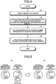
- FIG. 4 is a flowchart explaining a method of connecting the optical transmitter module 30 and the transmitter side optical connector 20.
- the flange portion 23 of the transmitter side optical connector 20 is directly gripped, or the transmitter side optical connector 20 is gripped using a jig attached to the flange portion 23, and the ferrule 22 is inserted into the sleeve 35 of the optical transmitter module 30 (step S1).
- the transmitter side optical connector 20 is rotated, and the connector side screw portion 24 is screwed with the module side screw portion 37. At this time, the light is emitted from the light emitting unit 31, and the light quantity transmitted by the optical fiber 21 is measured on a proximal end side of the optical fiber 21 (step S2).
- the eccentricity might occur between an outer diameter center of the ferrule 22 and a core center of the optical fiber 21 inserted into the micro hole during the manufacturing process. Similarly, the eccentricity might also occur between a center of the light emitting unit 31 and a center of the sleeve 35 in the optical transmitter module 30.
- FIG. 5 is a diagram explaining the adjustment of the eccentricity between the optical transmitter module 30 and the transmitter side optical connector 20.
- FIG. 5(a) is a state before the adjustment of the eccentricity
- FIG. 5(b) is a state after the adjustment of the eccentricity.
- the eccentricity is illustrated on a large scale for an easy understanding.
- the transmission light quantity can be sequentially detected, and a position where the maximum light quantity is obtainable can be detected.
- the transmitter side optical connector 20 is rotated, and the connector side screw portion 24 is screwed with the module side screw portion 37, the transmitter side optical connector 20 is rotated in an opposite direction until the transmitter side optical connector 20 reaches a position for the maximum light quantity, whereby the eccentricity between the transmitter side optical connector 20 and the optical transmitter module 30 is adjusted (step S3).
- the transmitter side optical connector 20 and the optical transmitter module 30 are fixed by the fixing member 50 (step S4).
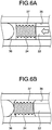
- the adjustment of the eccentricity is finished at the position in FIG. 6A .
- the light loss occurs since a space exists between the transparent glass body 36 and the distal end portion of the ferrule 22.
- the module side screw portion 37 is formed of the elastic member. Therefore, when the fixing member 50 is fit with the optical transmitter unit 10 in FIG. 6A subjected to the adjustment of the eccentricity, pressing force is exerted in a direction illustrated by an arrow in FIG. 6A , and the module side screw portion 37 is elastically deformed as illustrated in FIG. 6B . Consequently, the transparent glass body 36 and the distal end portion of the ferrule 22 can be brought into contact with each other and connected, and the light loss can be reduced.
- FIG. 7 is a view explaining a method of connecting an optical transmitter module and a transmitter side optical connector according to a first modification of the first embodiment of the present invention.
- a module side screw portion 37A is formed at a position apart from the transparent glass body 36 in the same way as that of the first embodiment illustrated in FIG. 6A .
- the module side screw portion 37A is pressed by the fixing member 50 and moves in a direction toward the transparent glass body 36 together with the ferrule 22.
- the pressing force of the fixing member 50 only needs to be set to be larger than frictional force between the sleeve 35 and the module side screw portion 37A. Consequently, the transparent glass body 36 and the distal end portion of the ferrule can be brought into contact with each other and connected, and the light loss can be reduced.
- FIG. 8 is a view explaining a method of connecting an optical transmitter module 30B and the transmitter side optical connector 20 according to a second modification of the first embodiment of the present invention.
- the optical transmitter module 30B and the transmitter side optical connector 20 are optically connected using the stub 41.
- a groove portion 41a is formed on an outer peripheral side of the stub 41 that is in contact with the sleeve 35.
- a module side screw portion 37B can move in a direction toward the stub 41 together with the ferrule 22 when pressed by the fixing member 50, and go into the groove portion 41a. Even in a case where the maximum light quantity is obtained when the distal end portion of the ferrule 22 is located before the rearmost end of the module side screw portion 37B, since the groove portion 41a is formed on the stub 41, the distal end portion of the ferrule 22 and the stub 41 can be brought into contact with each other and connected, and the light loss can be reduced.
- FIG. 9 is a side view of an optical transmitter unit according to a third modification of the first embodiment of the present invention.
- a marker 35e and a marker 25 are provided on the outer peripheral portion of the sleeve and the outer peripheral portion of a flange portion 23E, respectively.
- the adjustment of the eccentricity is facilitated by providing the marker 25 and the marker 35e.
- FIG. 10 is a view separately illustrating an optical transmitter module and a transmitter side optical connector in an optical transmitter unit according to a second embodiment of the present invention.
- a module side screw portion 37C is provided on an insertion opening side of the sleeve 35 for the ferrule 22, and a connector side screw portion 24C is provided on a side of the ferrule 22 located close to the flange portion 23.
- the ferrule 22 is inserted into the sleeve 35, a transmitter side optical connector 20C is rotated, and the connector side screw portion 24C is screwed with the module side screw portion 37C, whereby the transmitter side optical connector 20C is adjusted to reach a position for the maximum light quantity.
- an optical transmitter module 30C and the transmitter side optical connector 20C are pressed and fixed by the fixing member, and the transparent glass body 36 and the distal end portion of the ferrule 22 are brought into contact with each other and connected, whereby the light loss can be reduced.
- the module side screw portion 37C may be an elastic member, and the transparent glass body 36 and the distal end portion of the ferrule 22 may be connected in contact with each other by means of the elastic deformation of the module side screw portion 37C.
- the module side screw portion 37C may be configured to move through the inside of the sleeve 35 by means of the pressing force. A similar effect can be obtained when the transparent glass body 36 is replaced by the stub 41.
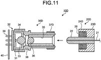
- FIG. 11 is a cross-sectional view explaining a method of connecting an optical transmitter module 30D and a transmitter side optical connector 20D according to a first modification of the second embodiment of the present invention.
- a flange portion 23D is formed to be thicker in diameter than the sleeve 35, and provided with, at a distal end side of the ferrule 22, an insertion portion 26 into which the sleeve 35 of the metal case 34 is inserted.
- a connector side screw portion 24D is provided in the insertion portion 26.
- the eccentricity can be adjusted to obtain the maximum light quantity, and the light loss can be reduced.
- a module side screw portion 37D may be an elastic member, and the transparent glass body 36 and the distal end portion of the ferrule 22 may be connected in contact with each other by means of the elastic deformation of the module side screw portion 37D.
- the module side screw portion 37D may be configured to move on the surface of the sleeve 35 by means of the pressing force.
- FIG. 12 is a schematic view illustrating an overview configuration of the optical transmission unit according to the third embodiment of the present invention.
- An optical transmission unit 100 includes an optical transmitter unit 10F, the optical fiber 21, and an optical receiving unit 80.
- the optical transmitter unit 10F is installed at the operating unit or the insertion portion of the endoscope, and the optical receiving unit 80 is installed in the processing device.
- the optical transmitter unit 10F is configured in such a manner that the optical transmitter module 30 and a transmitter side optical connector 20F illustrated in FIG. 12 are coupled and fixed by the fixing member.
- the optical transmitter module 30 has a configuration similar to that of the optical transmitter module 30 of the first embodiment.
- the transmitter side optical connector 20F includes a flange portion 23F in place of the flange portion 23 of the transmitter side optical connector 20 of the first embodiment.
- the flange portion 23F includes a groove 27 on an outer peripheral portion thereof. Since the flange portion 23F serves as a grip portion, a corner portion that constitutes the groove 27 is preferably rounded.
- the groove 27 may be provided over the entire periphery of the flange portion 23F, or may be partially provided.
- the optical receiving unit 80 is configured in such a manner that an optical receiving module 60 and a receiving side optical connector 70 illustrated in FIG. 12 are coupled and fixed by a fixing member.
- the optical receiving module 60 performs a photoelectric conversion on the optical signal transmitted by the optical fiber 21.
- the optical receiving module 60 includes a sleeve into which a ferrule 72 of the receiving side optical connector 70 to be described later is inserted, a module side screw portion is not formed in the sleeve.
- the receiving side optical connector 70 includes the ferrule 72 and a flange portion 73.
- the ferrule 72 holds the optical fiber 21.
- the flange portion 73 includes a groove 27 and is provided at one end of the ferrule 72.
- the flange portion 73 has the same shape as the flange portion 23F of the transmitter side optical connector 20F.
- the ferrule 72 is different from the ferrule 22 in that a distal end portion of the ferrule 72 does not include a connector side screw portion.
- a connector side screw portion and a module side screw portion similar to those of the optical transmitter unit 10C may be respectively provided on the ferrule 72 and inside a metal case of the optical receiving module, and may be fit with each other.
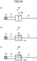
- the optical transmission units can be identified by changing the number of grooves formed on the flange portions of each optical transmission unit as illustrated in FIGS. 13 and 14 .
- the transmitter side optical connector 20F having the one groove 27 and the receiving side optical connector 70 having the one groove 27 constitute the optical transmission unit 100.
- a receiving side optical connector having two grooves 27G is used, and in an optical transmission unit that uses a transmitter side optical connector 20H having three grooves 27H illustrated in FIG. 13(c) , a receiving side optical connector having three grooves 27H is used, whereby the optical transmission units can be identified.
- transmitter side optical connectors having grooves 27, 27J, and 27K shaped as illustrated in FIG. 14 are used.
- the shapes of the grooves are not limited to those illustrated in FIGS. 13 and 14 .
Landscapes
- Health & Medical Sciences (AREA)
- Life Sciences & Earth Sciences (AREA)
- Physics & Mathematics (AREA)
- Surgery (AREA)
- Optics & Photonics (AREA)
- Engineering & Computer Science (AREA)
- Biomedical Technology (AREA)
- Veterinary Medicine (AREA)
- Biophysics (AREA)
- Pathology (AREA)
- Radiology & Medical Imaging (AREA)
- Nuclear Medicine, Radiotherapy & Molecular Imaging (AREA)
- Public Health (AREA)
- Heart & Thoracic Surgery (AREA)
- Medical Informatics (AREA)
- Molecular Biology (AREA)
- Animal Behavior & Ethology (AREA)
- General Health & Medical Sciences (AREA)
- General Physics & Mathematics (AREA)
- Signal Processing (AREA)
- Astronomy & Astrophysics (AREA)
- Multimedia (AREA)
- Endoscopes (AREA)
- Optical Couplings Of Light Guides (AREA)
- Instruments For Viewing The Inside Of Hollow Bodies (AREA)
Abstract
Description
- The present invention relates to an optical transmitter unit, a method of connecting an optical transmitter module and a transmitter side optical connector, and an endoscope system.
- Conventionally, an endoscope system is used in the medical field when an organ of a subject such as a patient is observed. The endoscope system includes, for example, an endoscope and a processing device. The endoscope includes an insertion portion formed in a flexible elongated shape, a distal end of which is provided with an imaging sensor. The insertion portion is inserted into a body cavity of the subject. The processing device is coupled to the insertion portion via a cable and a connector to perform an image process on an in-vivo image captured by the imaging sensor. The processing device causes a display device to display the in-vivo image.
- In recent years, an imaging sensor with a large number of pixels which enables a clearer image observation has been developed, and the use of the imaging sensor with a large number of pixels for the endoscope has been considered. In addition, the insertion portion is required to be reduced in diameter in consideration of easiness of introduction into the subject. Furthermore, in order to transmit a large volume of signals between the imaging sensor and the processing device at high speed while realizing the reduction in the diameter of the insertion portion, an optical transmission system that transmits a signal using laser light is employed in the endoscope system.
- In the optical transmission system with the use of the laser light or the like, it is important to perform the transmission without reducing the light quantity of an optical signal emitted from a light emitting element such as a laser diode. As an example of such a technique, an optical connector and an aligning method have been disclosed in which a plurality of fitting portions and cutouts having different lengths in an axial direction are provided on an outer peripheral surface of a base fixed to a ferrule, the ferrule is rotated at an interval (90 degrees) of the provided fitting portions to adjust eccentricity (aligning), and fixation and coupling are performed (for example, refer to Patent Literature 1).
- Patent Literature 1:
JP H11-38276 A - Although the adjustment of the eccentricity as well as the fixation and the coupling can be easily performed in
Patent Literature 1, the eccentricity can only be adjusted every 90 degrees. Therefore, it is difficult to adjust the eccentricity so that the optical signal is transmitted using the maximum light quantity, which results in a significant light loss. - The present invention has been made in consideration of the above-mentioned circumstances, and an object thereof is to provide an optical transmitter unit, a method of connecting an optical transmitter module and a transmitter side optical connector, and an endoscope system which reduce a light loss in optical transmission.
- To solve the above-described problem and achieve the object, an optical transmitter unit according to the present invention includes: an optical transmitter module configured to convert an electric signal into an optical signal and transmit the optical signal; and a transmitter side optical connector connected to the optical transmitter module and configured to hold an end portion of an optical fiber transmitting the optical signal, wherein the transmitter side optical connector includes a ferrule configured to hold the optical fiber, and a flange portion provided at one end of the ferrule, the optical transmitter module includes a light emitting element, and a metal case configured to store the light emitting element, a connector side screw portion is provided on the ferrule or the flange portion, and a module side screw portion formed of an elastic member and configured to be screwed with the connector side screw portion is provided in a sleeve of the metal case into which the ferrule is inserted, and the module side screw portion is elastically deformed by pressing force of a fixing member when the transmitter side optical connector and the optical transmitter module are pressed and fixed by the fixing member.
- Moreover, an optical transmitter unit according to the present invention includes: an optical transmitter module configured to convert an electric signal into an optical signal and transmit the optical signal; and a transmitter side optical connector connected to the optical transmitter module and configured to hold an end portion of an optical fiber transmitting the optical signal, wherein the transmitter side optical connector includes a ferrule configured to hold the optical fiber, and a flange portion provided at one end of the ferrule, the optical transmitter module includes a light emitting element, and a metal case configured to store the light emitting element, a connector side screw portion is provided on the ferrule or the flange portion, and a module side screw portion configured to be screwed with the connector side screw portion is provided in a sleeve of the metal case into which the ferrule is inserted, and the module side screw portion moves by means of pressing force of a fixing member when the transmitter side optical connector and the optical transmitter module are pressed and fixed by the fixing member.
- Moreover, in the above-described optical transmitter unit according to the present invention, positioning markers are provided on an outer peripheral portion of the sleeve and an outer peripheral portion of the flange portion.
- Moreover, a method of connecting the optical transmitter module and the transmitter side optical connector in one of the above-described optical transmitter units includes: a step of inserting the ferrule into the sleeve of the metal case; a light quantity measuring step of measuring a light quantity of emission light emitted from the light emitting element and transmitted by the optical fiber while rotating the transmitter side optical connector such that the connector side screw portion provided on the ferrule or the flange portion and the module side screw portion provided in the sleeve are screwed with each other; an eccentricity adjusting step of rotating the transmitter side optical connector to place the transmitter side optical connector and the optical transmitter module at a position where a maximum light quantity is obtainable based on a measurement result obtained in the light quantity measuring step; and a fixing step of pressing and fixing the transmitter side optical connector and the optical transmitter module using the fixing member.
- Moreover, an endoscope system according to the present invention is inserted into a subject and captures an inside of the subject, the endoscope system including: a light source unit configured to emit light with which the inside of the subject is irradiated; an imaging unit configured to perform a photoelectric conversion on light reflected from the subject to generate an image signal; an optical transmission unit including: one of the above-described optical transmitter units configured to perform a photoelectric conversion on the image signal and transmit an optical signal obtained by the conversion using the optical fiber; an optical receiving module configured to perform a photoelectric conversion on the optical signal transmitted by the optical fiber; and a receiving side optical connector configured to connect the optical fiber to the optical receiving module; and an image processing unit configured to process the image signal based on a signal transmitted by the optical transmission unit.
- Moreover, the above-described endoscope system according to the present invention includes a plurality of the optical transmission units, wherein grooves are formed on a flange of the transmitter side optical connector and a flange of the receiving side optical connector, and different types of the grooves are provided on the respective optical transmission units.
- According to the present invention, screw portions are provided on a ferrule or a flange portion and in a sleeve into which the ferrule is inserted, and a transmitter side optical connector and an optical transmitter module can be placed at a position for the maximum light quantity while the screw portions are rotated so as to be screwed with each other. The transmitter side optical connector and the optical transmitter module can also be brought into close contact with each other. Therefore, a light loss at the time of transmission can be reduced.
-
-
FIG. 1 is a schematic view illustrating an overview configuration of an endoscope system according to a first embodiment of the present invention. -
FIG. 2 is a view separately illustrating an optical transmitter module and a transmitter side optical connector that constitute an optical transmitter unit used in the endoscope system illustrated inFIG. 1 . -
FIG. 3 is a side view of the optical transmitter unit illustrated inFIG. 2 . -
FIG. 4 is a flowchart explaining a method of connecting the optical transmitter module and the transmitter side optical connector. -
FIG. 5 is a diagram explaining an adjustment of eccentricity between the optical transmitter module and the transmitter side optical connector. -
FIG. 6A is a view explaining the method of connecting the optical transmitter module and the transmitter side optical connector. -
FIG. 6B is a view explaining the method of connecting the optical transmitter module and the transmitter side optical connector. -
FIG. 7 is a view explaining a method of connecting an optical transmitter module and a transmitter side optical connector according to a first modification of the first embodiment of the present invention. -
FIG. 8 is a view explaining a method of connecting an optical transmitter module and a transmitter side optical connector in an optical transmitter unit according to a second modification of the first embodiment of the present invention. -
FIG. 9 is a side view of an optical transmitter unit according to a third modification of the first embodiment of the present invention. -
FIG. 10 is a view separately illustrating an optical transmitter module and a transmitter side optical connector in an optical transmitter unit according to a second embodiment of the present invention. -
FIG. 11 is a view explaining a method of connecting an optical transmitter module and a transmitter side optical connector in an optical transmitter unit according to a first modification of the second embodiment of the present invention. -
FIG. 12 is a schematic view illustrating an overview configuration of an optical transmission unit according to a third embodiment of the present invention. -
FIG. 13 is a view explaining a groove provided on a flange portion of a transmitter side optical connector according to the third embodiment of the present invention. -
FIG. 14 is a view explaining a groove provided on a flange portion of a transmitter side optical connector according to a modification of the third embodiment of the present invention. - In the following description, as an embodiment for practicing the present invention (hereinafter referred to as the "embodiment"), an endoscope system will be described. The present invention is not limited by the embodiments. In the drawings, identical elements are provided with the same reference signs.
-
FIG. 1 is a schematic view illustrating an overview configuration of an endoscope system according to a first embodiment of the present invention. As illustrated inFIG. 1 , anendoscope system 1 according to the present embodiment includes anendoscope 2, aprocessing device 3, alight source device 4, and adisplay device 5. Theendoscope 2 is introduced into a subject and captures the inside of a body of the subject to generate an image signal of the inside of the subject. Theprocessing device 3 performs a predetermined image process on the image signal captured by theendoscope 2, and controls each part of theendoscope system 1. Thelight source device 4 generates illumination light of theendoscope 2. Thedisplay device 5 displays an image of the image signal subjected to the image process by theprocessing device 3. - The
endoscope 2 includes aninsertion portion 6, an operating unit 7, and a flexibleuniversal code 8. Theinsertion portion 6 is inserted into the subject. The operating unit 7 is located on a proximal end portion side of theinsertion portion 6 and gripped by an operator. Theuniversal code 8 extends from the operating unit 7. - The
insertion portion 6 is realized with the use of an illumination fiber (light guide cable), an electric cable, and an optical fiber or the like. Theinsertion portion 6 includes adistal end portion 6a, acurve portion 6b, and aflexible pipe portion 6c. Thedistal end portion 6a includes an imaging unit in which an imaging sensor that captures the inside of the subject is incorporated. Thecurve portion 6b includes a plurality of curve pieces so as to be freely curved. Theflexible pipe portion 6c is provided on a proximal end portion side of thecurve portion 6b and has flexibility. Thedistal end portion 6a is provided with an illumination unit, an observation unit, anopening portion 6d, and an air/water supply nozzle (not illustrated). The illumination unit illuminates the inside of the subject through an illumination lens. The observation unit captures the inside of the subject. Theopening portion 6d communicates with a processing tool channel. - The operating unit 7 includes a
curve knob 7a, a treatmenttool insertion portion 7b, and a plurality ofswitch units 7c. Thecurve knob 7a curves thecurve portion 6b in an up-down direction and a left-right direction. A treatment tool such as living body forceps and a laser scalpel is inserted into a body cavity of the subject through the treatmenttool insertion portion 7b. A peripheral device such as theprocessing device 3, thelight source device 4, an air supply device, a water supply device, and a gas supply device is operated through the plurality ofswitch units 7c. The treatment tool inserted through the treatmenttool insertion portion 7b passes through a treatment tool channel provided inside and comes out of theopening portion 6d at the distal end of theinsertion portion 6. - The
universal code 8 is configured with the use of an illumination fiber, an electric cable, and an optical fiber or the like. Theuniversal code 8 branches at a proximal end thereof. An end portion of one of the branches is aconnector 8a, and an end portion of the other is aconnector 8b. Theconnector 8a is detachably attached to aconnector 3a of theprocessing device 3. Theconnector 8b is detachably attached to thelight source device 4. Theuniversal code 8 propagates the illumination light emitted from thelight source device 4 to thedistal end portion 6a through theconnector 8b, the operating unit 7, and theflexible pipe portion 6c. Theuniversal code 8 transmits the image signal captured by the imaging unit provided in thedistal end portion 6a to theprocessing device 3 by means of an optical transmitter unit to be described later. - The
processing device 3 performs the predetermined image process on the image signal of the inside of the subject captured by the imaging unit of thedistal end portion 6a of theendoscope 2. Theprocessing device 3 controls each part of theendoscope system 1 based on various instruction signals transmitted from theswitch units 7c of the operating unit 7 of theendoscope 2 through theuniversal code 8. - The
light source device 4 is configured with the use of a light source that emits light and a condenser lens or the like. Under the control of theprocessing device 3, thelight source device 4 emits the light from the light source and supplies, to theendoscope 2 coupled via theconnector 8b and the illumination fiber of theuniversal code 8, the light as the illumination light for the inside of the subject that serves as an object. - The
display device 5 is configured with the use of a display or the like in which liquid crystal or organic electro luminescence (EL) is used. Thedisplay device 5 displays, through avideo cable 5a, various types of information including the image subjected to the predetermined image process by theprocessing device 3. Consequently, the operator can observe a desired position in the subject and determine the condition of the desired position by operating theendoscope 2 while watching the image (in-vivo image) displayed by thedisplay device 5. - Next, in the
endoscope 2 described inFIG. 1 , the optical transmitter unit that transmits the image signal captured by the imaging unit to the processing device will be described.FIG. 2 is a view separately illustrating an optical transmitter module and a transmitter side optical connector that constitute the optical transmitter unit used in the endoscope system illustrated inFIG. 1 . InFIG. 2 , for an easy understanding, anoptical transmitter module 30 is illustrated in a cross-sectional view, a transmitter sideoptical connector 20 is illustrated in a side view, and a fixing member is not illustrated.FIG. 3 is a side view of anoptical transmitter unit 10 illustrated inFIG. 2 . - The
optical transmitter unit 10 is configured in such a manner that the transmitter sideoptical connector 20 and theoptical transmitter module 30 are coupled by a fixingmember 50 as illustrated inFIGS. 2 and 3 . Theoptical transmitter unit 10 is arranged at the operating unit 7 or theinsertion portion 6 of theendoscope 2. - The transmitter side
optical connector 20 includes aferrule 22 and aflange portion 23. Theferrule 22 holds anoptical fiber 21. Theflange portion 23 is provided at one end of theferrule 22. In theferrule 22 having a substantially columnar shape, a micro hole (not illustrated) that passes through a center of the columnar shape in an axial direction is provided. Theoptical fiber 21 is inserted into the micro hole, whereby the transmitter sideoptical connector 20 holds theoptical fiber 21. Theoptical fiber 21 is inserted into the micro hole and exposed at an end surface (hereinafter referred to as a "distal end portion") of theferrule 22 that is inserted into asleeve 35. An end surface of theoptical fiber 21 is polished in order to reduce a loss of the light quantity at an optical connection portion. A connectorside screw portion 24 is formed on an outer peripheral portion of theferrule 22 located on an insertion portion side. Theflange portion 23 having a columnar shape that is concentric with theferrule 22 is provided on an outer peripheral portion of theferrule 22 located opposite to the distal end portion (hereinafter referred to as a "proximal end portion"). - The
optical transmitter module 30 includes alight emitting element 32 and ametal case 34. Themetal case 34 stores and optically connects thelight emitting element 32 and theferrule 22. Thelight emitting element 32 is coupled to aflexible substrate 40 via alead 39. The image signal captured by the imaging unit is transmitted to thelight emitting element 32 through theflexible substrate 40, subjected to a photoelectric conversion, and emitted from alight emitting unit 31 as an optical signal. The optical signal emitted from thelight emitting unit 31 is collected by acondenser lens 33 and atransparent glass body 36. Themetal case 34 includes thesleeve 35 into which theferrule 22 is inserted. A moduleside screw portion 37 that is screwed with the connectorside screw portion 24 is provided in the vicinity of thetransparent glass body 36 in thesleeve 35. The moduleside screw portion 37 is formed of an elastic deformable material such as rubber. - The
ferrule 22 is inserted into thesleeve 35 of theoptical transmitter module 30, the connectorside screw portion 24 and the moduleside screw portion 37 are screwed with each other, and eccentricity is adjusted. After that, as illustrated inFIG. 3 , theoptical transmitter module 30 is fixed by the fixingmember 50 that presses theferrule 22 in thesleeve 35 of themetal case 34. The fixingmember 50 is made of a metal material, and includesU-shaped holding portions portions optical transmitter unit 10 in an opening direction of the U shape, and fixed. The holdingportion 51 is fit with a recessedportion 38 of themetal case 34, and the holdingportion 52 is fit with a proximal end side of theflange portion 23 of the transmitter sideoptical connector 20. The length between the holdingportion 51 and the holdingportion 52 is designed to be shorter than the length from the recessedportion 38 to the proximal end portion of theflange portion 23. Therefore, when the fixingmember 50 is fit with theoptical transmitter unit 10, the fixingmember 50 performs the fixation while pressing theferrule 22 in thesleeve 35. - Next, a connecting method for the
optical transmitter unit 10 will be described.FIG. 4 is a flowchart explaining a method of connecting theoptical transmitter module 30 and the transmitter sideoptical connector 20. - First, the
flange portion 23 of the transmitter sideoptical connector 20 is directly gripped, or the transmitter sideoptical connector 20 is gripped using a jig attached to theflange portion 23, and theferrule 22 is inserted into thesleeve 35 of the optical transmitter module 30 (step S1). - After the
ferrule 22 is inserted into thesleeve 35, the transmitter sideoptical connector 20 is rotated, and the connectorside screw portion 24 is screwed with the moduleside screw portion 37. At this time, the light is emitted from thelight emitting unit 31, and the light quantity transmitted by theoptical fiber 21 is measured on a proximal end side of the optical fiber 21 (step S2). - In the transmitter side
optical connector 20, the eccentricity might occur between an outer diameter center of theferrule 22 and a core center of theoptical fiber 21 inserted into the micro hole during the manufacturing process. Similarly, the eccentricity might also occur between a center of thelight emitting unit 31 and a center of thesleeve 35 in theoptical transmitter module 30. -
FIG. 5 is a diagram explaining the adjustment of the eccentricity between theoptical transmitter module 30 and the transmitter sideoptical connector 20.FIG. 5(a) is a state before the adjustment of the eccentricity, andFIG. 5(b) is a state after the adjustment of the eccentricity. InFIGS. 5(a) and 5(b) , the eccentricity is illustrated on a large scale for an easy understanding. - In a case where the eccentric transmitter side
optical connector 20 and the eccentricoptical transmitter module 30 are optically connected, no problem occurs when a direction of the eccentricity of the transmitter sideoptical connector 20 is the same as that of theoptical transmitter module 30. However, in a case where the directions are different from each other as illustrated inFIG. 5(a) , the transmission light quantity is significantly reduced if the transmitter sideoptical connector 20 and theoptical transmitter module 30 are connected as they are. In a case where the transmitter sideoptical connector 20 and theoptical transmitter module 30 that are eccentric in the different directions are connected, for example, the transmitter sideoptical connector 20 is rotated as illustrated by an arrow inFIG. 5(a) , whereby the direction of the eccentricity between the transmitter sideoptical connector 20 and theoptical transmitter module 30 can be adjusted as illustrated inFIG. 5(b) , and the light loss can be reduced. In the first embodiment, since the connectorside screw portion 24 and the moduleside screw portion 37 are screwed with each other to adjust the eccentricity, the transmission light quantity can be sequentially detected, and a position where the maximum light quantity is obtainable can be detected. - After the transmitter side
optical connector 20 is rotated, and the connectorside screw portion 24 is screwed with the moduleside screw portion 37, the transmitter sideoptical connector 20 is rotated in an opposite direction until the transmitter sideoptical connector 20 reaches a position for the maximum light quantity, whereby the eccentricity between the transmitter sideoptical connector 20 and theoptical transmitter module 30 is adjusted (step S3). - After the eccentricity between the transmitter side
optical connector 20 and theoptical transmitter module 30 is adjusted, the transmitter sideoptical connector 20 and theoptical transmitter module 30 are fixed by the fixing member 50 (step S4). - In a case where the light quantity is measured in step S2, and the maximum light quantity is obtained when the distal end portion of the
ferrule 22 is located at the rearmost end of the moduleside screw portion 37 as illustrated inFIG. 6A , the adjustment of the eccentricity is finished at the position inFIG. 6A . However, the light loss occurs since a space exists between thetransparent glass body 36 and the distal end portion of theferrule 22. In the first embodiment, the moduleside screw portion 37 is formed of the elastic member. Therefore, when the fixingmember 50 is fit with theoptical transmitter unit 10 inFIG. 6A subjected to the adjustment of the eccentricity, pressing force is exerted in a direction illustrated by an arrow inFIG. 6A , and the moduleside screw portion 37 is elastically deformed as illustrated inFIG. 6B . Consequently, thetransparent glass body 36 and the distal end portion of theferrule 22 can be brought into contact with each other and connected, and the light loss can be reduced. - Alternatively, the module side screw portion may move through the inside of the
sleeve 35 instead of being elastically deformed by the pressing force caused by the fixingmember 50.FIG. 7 is a view explaining a method of connecting an optical transmitter module and a transmitter side optical connector according to a first modification of the first embodiment of the present invention. In the first modification, a moduleside screw portion 37A is formed at a position apart from thetransparent glass body 36 in the same way as that of the first embodiment illustrated inFIG. 6A . However, the moduleside screw portion 37A is pressed by the fixingmember 50 and moves in a direction toward thetransparent glass body 36 together with theferrule 22. In the first modification, the pressing force of the fixingmember 50 only needs to be set to be larger than frictional force between thesleeve 35 and the moduleside screw portion 37A. Consequently, thetransparent glass body 36 and the distal end portion of the ferrule can be brought into contact with each other and connected, and the light loss can be reduced. - In addition, a similar effect can be obtained in the optical transmitter module that uses a
stub 41 in place of thetransparent glass body 36.FIG. 8 is a view explaining a method of connecting anoptical transmitter module 30B and the transmitter sideoptical connector 20 according to a second modification of the first embodiment of the present invention. In the second modification, theoptical transmitter module 30B and the transmitter sideoptical connector 20 are optically connected using thestub 41. Agroove portion 41a is formed on an outer peripheral side of thestub 41 that is in contact with thesleeve 35. In the same way as the moduleside screw portion 37A of the first modification, a moduleside screw portion 37B can move in a direction toward thestub 41 together with theferrule 22 when pressed by the fixingmember 50, and go into thegroove portion 41a. Even in a case where the maximum light quantity is obtained when the distal end portion of theferrule 22 is located before the rearmost end of the moduleside screw portion 37B, since thegroove portion 41a is formed on thestub 41, the distal end portion of theferrule 22 and thestub 41 can be brought into contact with each other and connected, and the light loss can be reduced. - In the first embodiment, the adjustment of the eccentricity between the optical transmitter module and the transmitter side optical connector is performed by causing the screw portions provided in the sleeve and on the surface of the ferrule to be fit with each other. Alternatively, the adjustment of the eccentricity can be easily performed by providing a positioning marker on each of an outer peripheral portion of the sleeve and an outer peripheral portion of the flange portion.
FIG. 9 is a side view of an optical transmitter unit according to a third modification of the first embodiment of the present invention. In theoptical transmitter unit 10E according to the third modification, amarker 35e and amarker 25 are provided on the outer peripheral portion of the sleeve and the outer peripheral portion of aflange portion 23E, respectively. The adjustment of the eccentricity is facilitated by providing themarker 25 and themarker 35e. -
FIG. 10 is a view separately illustrating an optical transmitter module and a transmitter side optical connector in an optical transmitter unit according to a second embodiment of the present invention. In anoptical transmitter unit 10C according to the second embodiment of the present invention, a moduleside screw portion 37C is provided on an insertion opening side of thesleeve 35 for theferrule 22, and a connectorside screw portion 24C is provided on a side of theferrule 22 located close to theflange portion 23. - In the second embodiment as well, the
ferrule 22 is inserted into thesleeve 35, a transmitter sideoptical connector 20C is rotated, and the connectorside screw portion 24C is screwed with the moduleside screw portion 37C, whereby the transmitter sideoptical connector 20C is adjusted to reach a position for the maximum light quantity. After that, anoptical transmitter module 30C and the transmitter sideoptical connector 20C are pressed and fixed by the fixing member, and thetransparent glass body 36 and the distal end portion of theferrule 22 are brought into contact with each other and connected, whereby the light loss can be reduced. In the same way as the moduleside screw portion 37 of the first embodiment, the moduleside screw portion 37C may be an elastic member, and thetransparent glass body 36 and the distal end portion of theferrule 22 may be connected in contact with each other by means of the elastic deformation of the moduleside screw portion 37C. Alternatively, in the same way as the moduleside screw portion 37A of the first modification of the first embodiment, the moduleside screw portion 37C may be configured to move through the inside of thesleeve 35 by means of the pressing force. A similar effect can be obtained when thetransparent glass body 36 is replaced by thestub 41. - In addition, the module side screw portion provided on the insertion opening side of the
sleeve 35 for theferrule 22 may be provided on the outer peripheral portion of thesleeve 35, not in thesleeve 35.FIG. 11 is a cross-sectional view explaining a method of connecting anoptical transmitter module 30D and a transmitter sideoptical connector 20D according to a first modification of the second embodiment of the present invention. In anoptical transmitter unit 10D according to the first modification of the second embodiment, aflange portion 23D is formed to be thicker in diameter than thesleeve 35, and provided with, at a distal end side of theferrule 22, aninsertion portion 26 into which thesleeve 35 of themetal case 34 is inserted. A connectorside screw portion 24D is provided in theinsertion portion 26. In the first modification of the second embodiment as well, the eccentricity can be adjusted to obtain the maximum light quantity, and the light loss can be reduced. In the same way as the moduleside screw portion 37 of the first embodiment, a moduleside screw portion 37D may be an elastic member, and thetransparent glass body 36 and the distal end portion of theferrule 22 may be connected in contact with each other by means of the elastic deformation of the moduleside screw portion 37D. Alternatively, in the same way as the moduleside screw portion 37A of the first modification of the first embodiment, the moduleside screw portion 37D may be configured to move on the surface of thesleeve 35 by means of the pressing force. - In an endoscope of a third embodiment, the transmission of the image signal is performed using a plurality of optical transmission units.
FIG. 12 is a schematic view illustrating an overview configuration of the optical transmission unit according to the third embodiment of the present invention. - An
optical transmission unit 100 includes anoptical transmitter unit 10F, theoptical fiber 21, and anoptical receiving unit 80. Theoptical transmitter unit 10F is installed at the operating unit or the insertion portion of the endoscope, and the optical receivingunit 80 is installed in the processing device. Theoptical transmitter unit 10F is configured in such a manner that theoptical transmitter module 30 and a transmitter sideoptical connector 20F illustrated inFIG. 12 are coupled and fixed by the fixing member. Theoptical transmitter module 30 has a configuration similar to that of theoptical transmitter module 30 of the first embodiment. The transmitter sideoptical connector 20F includes aflange portion 23F in place of theflange portion 23 of the transmitter sideoptical connector 20 of the first embodiment. Theflange portion 23F includes agroove 27 on an outer peripheral portion thereof. Since theflange portion 23F serves as a grip portion, a corner portion that constitutes thegroove 27 is preferably rounded. Thegroove 27 may be provided over the entire periphery of theflange portion 23F, or may be partially provided. - The
optical receiving unit 80 is configured in such a manner that anoptical receiving module 60 and a receiving sideoptical connector 70 illustrated inFIG. 12 are coupled and fixed by a fixing member. Theoptical receiving module 60 performs a photoelectric conversion on the optical signal transmitted by theoptical fiber 21. Although theoptical receiving module 60 includes a sleeve into which aferrule 72 of the receiving sideoptical connector 70 to be described later is inserted, a module side screw portion is not formed in the sleeve. The receiving sideoptical connector 70 includes theferrule 72 and aflange portion 73. Theferrule 72 holds theoptical fiber 21. Theflange portion 73 includes agroove 27 and is provided at one end of theferrule 72. In the third embodiment, theflange portion 73 has the same shape as theflange portion 23F of the transmitter sideoptical connector 20F. However, theferrule 72 is different from theferrule 22 in that a distal end portion of theferrule 72 does not include a connector side screw portion. Alternatively, in order to perform the adjustment in the optical receivingunit 80 so that the light quantity received at theoptical receiving module 60 is equal to or more than the lowest receiving sensitivity, a connector side screw portion and a module side screw portion similar to those of theoptical transmitter unit 10C may be respectively provided on theferrule 72 and inside a metal case of the optical receiving module, and may be fit with each other. - In a case where the image signal is transmitted using the plurality of optical transmission units, an insertion error might occur since the optical transmission units cannot be identified. In the third embodiment, therefore, different types of grooves are provided on the respective optical transmission units in order to identify the plurality of optical transmission units. For example, in a case where three types of optical transmission units are used, the optical transmission units can be identified by changing the number of grooves formed on the flange portions of each optical transmission unit as illustrated in
FIGS. 13 and14 . InFIG. 12 , the transmitter sideoptical connector 20F having the onegroove 27 and the receiving sideoptical connector 70 having the onegroove 27 constitute theoptical transmission unit 100. In an optical transmission unit that uses a transmitter sideoptical connector 20G having twogrooves 27G illustrated inFIG. 13(b) , a receiving side optical connector having twogrooves 27G is used, and in an optical transmission unit that uses a transmitter sideoptical connector 20H having threegrooves 27H illustrated inFIG. 13(c) , a receiving side optical connector having threegrooves 27H is used, whereby the optical transmission units can be identified. The same applies to a case where transmitter side opticalconnectors having grooves FIG. 14 are used. The shapes of the grooves are not limited to those illustrated inFIGS. 13 and14 . Reference Signs List -
- 1 ENDOSCOPE SYSTEM
- 2 ENDOSCOPE
- 3 PROCESSING DEVICE
- 4 LIGHT SOURCE DEVICE
- 5 DISPLAY DEVICE
- 6 INSERTION PORTION
- 6a DISTAL END PORTION
- 6b CURVE PORTION
- 6c FLEXIBLE PIPE PORTION
- 6d OPENING PORTION
- 7 OPERATING UNIT
- 7a CURVE KNOB
- 7b TREATMENT TOOL INSERTION PORTION
- 7c SWITCH UNIT
- 8 UNIVERSAL CODE
- 8a, 8b CONNECTOR
- 10, 10B, 10C, 10D, 10E OPTICAL TRANSMITTER UNIT
- 20, 20C, 20D, 20E, 20F, 20G, 20H, 20J, 20K TRANSMITTER SIDE OPTICAL CONNECTOR
- 21 OPTICAL FIBER
- 22, 72 FERRULE
- 23, 23D, 23E, 73 FLANGE PORTION
- 24, 24C, 24D CONNECTOR SIDE SCREW PORTION
- 25, 35e MARKER
- 26 INSERTION PORTION
- 27 GROOVE
- 30, 30B, 30C, 30D, 30E OPTICAL TRANSMITTER MODULE
- 31 LIGHT EMITTING UNIT
- 32 LIGHT EMITTING ELEMENT
- 33 CONDENSER LENS
- 34 METAL CASE
- 35 SLEEVE
- 36 TRANSPARENT GLASS BODY
- 37, 37A, 37B, 37C, 37D MODULE SIDE SCREW PORTION
- 38 RECESSED PORTION
- 39 LEAD
- 40 FLEXIBLE SUBSTRATE
- 41 STUB
- 50 FIXING MEMBER
- 51, 52 HOLDING PORTION
- 60 OPTICAL RECEIVING MODULE
- 70 RECEIVING SIDE OPTICAL CONNECTOR
- 80 OPTICAL RECEIVING UNIT
- 100 OPTICAL TRANSMISSION UNIT
Claims (6)
- An optical transmitter unit comprising:an optical transmitter module configured to convert an electric signal into an optical signal and transmit the optical signal; anda transmitter side optical connector connected to the optical transmitter module and configured to hold an end portion of an optical fiber transmitting the optical signal, whereinthe transmitter side optical connector includesa ferrule configured to hold the optical fiber, anda flange portion provided at one end of the ferrule,the optical transmitter module includesa light emitting element, anda metal case configured to store the light emitting element,a connector side screw portion is provided on the ferrule or the flange portion, and a module side screw portion formed of an elastic member and configured to be screwed with the connector side screw portion is provided in a sleeve of the metal case into which the ferrule is inserted, andthe module side screw portion is elastically deformed by pressing force of a fixing member when the transmitter side optical connector and the optical transmitter module are pressed and fixed by the fixing member.
- An optical transmitter unit comprising:an optical transmitter module configured to convert an electric signal into an optical signal and transmit the optical signal; anda transmitter side optical connector connected to the optical transmitter module and configured to hold an end portion of an optical fiber transmitting the optical signal, whereinthe transmitter side optical connector includesa ferrule configured to hold the optical fiber, anda flange portion provided at one end of the ferrule,the optical transmitter module includesa light emitting element, anda metal case configured to store the light emitting element,a connector side screw portion is provided on the ferrule or the flange portion, and a module side screw portion configured to be screwed with the connector side screw portion is provided in a sleeve of the metal case into which the ferrule is inserted, andthe module side screw portion moves by means of pressing force of a fixing member when the transmitter side optical connector and the optical transmitter module are pressed and fixed by the fixing member.
- The optical transmitter unit according to claim 1 or 2, wherein
positioning markers are provided on an outer peripheral portion of the sleeve and an outer peripheral portion of the flange portion. - A method of connecting the optical transmitter module and the transmitter side optical connector in the optical transmitter unit according to any one of claims 1 to 3, the method comprising:a step of inserting the ferrule into the sleeve of the metal case;a light quantity measuring step of measuring a light quantity of emission light emitted from the light emitting element and transmitted by the optical fiber while rotating the transmitter side optical connector such that the connector side screw portion provided on the ferrule or the flange portion and the module side screw portion provided in the sleeve are screwed with each other;an eccentricity adjusting step of rotating the transmitter side optical connector to place the transmitter side optical connector and the optical transmitter module at a position where a maximum light quantity is obtainable based on a measurement result obtained in the light quantity measuring step; anda fixing step of pressing and fixing the transmitter side optical connector and the optical transmitter module using the fixing member.
- An endoscope system for being inserted into a subject and capturing an inside of the subject, the endoscope system comprising:a light source unit configured to emit light with which the inside of the subject is irradiated;an imaging unit configured to perform a photoelectric conversion on light reflected from the subject to generate an image signal;an optical transmission unit including:the optical transmitter unit according to any one of claims 1 to 3 configured to perform a photoelectric conversion on the image signal and transmit an optical signal obtained by the conversion using the optical fiber;an optical receiving module configured to perform a photoelectric conversion on the optical signal transmitted by the optical fiber; anda receiving side optical connector configured to connect the optical fiber to the optical receiving module; andan image processing unit configured to process the image signal based on a signal transmitted by the optical transmission unit.
- The endoscope system according to claim 5, comprising a plurality of the optical transmission units, wherein
grooves are formed on a flange of the transmitter side optical connector and a flange of the receiving side optical connector, and different types of the grooves are provided on the respective optical transmission units.
Applications Claiming Priority (2)
| Application Number | Priority Date | Filing Date | Title |
|---|---|---|---|
| JP2014191851 | 2014-09-19 | ||
| PCT/JP2015/062564 WO2016042828A1 (en) | 2014-09-19 | 2015-04-24 | Optical transmitter unit, method for connecting optical transmitter module and transmission-side optical connector, and endoscope system |
Publications (2)
| Publication Number | Publication Date |
|---|---|
| EP3195792A1 true EP3195792A1 (en) | 2017-07-26 |
| EP3195792A4 EP3195792A4 (en) | 2018-06-06 |
Family
ID=55532875
Family Applications (1)
| Application Number | Title | Priority Date | Filing Date |
|---|---|---|---|
| EP15842698.1A Withdrawn EP3195792A4 (en) | 2014-09-19 | 2015-04-24 | Optical transmitter unit, method for connecting optical transmitter module and transmission-side optical connector, and endoscope system |
Country Status (5)
| Country | Link |
|---|---|
| US (1) | US20170184836A1 (en) |
| EP (1) | EP3195792A4 (en) |
| JP (1) | JP6062076B2 (en) |
| CN (1) | CN106687025A (en) |
| WO (1) | WO2016042828A1 (en) |
Families Citing this family (6)
| Publication number | Priority date | Publication date | Assignee | Title |
|---|---|---|---|---|
| CN106725261A (en) * | 2017-01-13 | 2017-05-31 | 苏新军 | Treatment mirror is peeped in a kind of fixed optical fiber |
| US11166622B2 (en) * | 2020-02-21 | 2021-11-09 | Ambu A/S | Video processing apparatus |
| US10980397B1 (en) | 2020-02-21 | 2021-04-20 | Ambu A/S | Video processing device |
| CN111381329A (en) * | 2020-04-07 | 2020-07-07 | 武汉电信器件有限公司 | Coupling adapter |
| US11287580B1 (en) * | 2020-09-16 | 2022-03-29 | Berk-Tek Llc | Armored cable and connection for the same |
| WO2025254233A1 (en) * | 2024-06-04 | 2025-12-11 | 배석만 | Led light source assembly and side lighting device employing same |
Family Cites Families (18)
| Publication number | Priority date | Publication date | Assignee | Title |
|---|---|---|---|---|
| JPS5744116A (en) * | 1980-08-29 | 1982-03-12 | Olympus Optical Co Ltd | Connector device of endoscope |
| US4697870A (en) * | 1983-01-25 | 1987-10-06 | Pilling Co. | Termination for light-conducting cable |
| US4641912A (en) * | 1984-12-07 | 1987-02-10 | Tsvi Goldenberg | Excimer laser delivery system, angioscope and angioplasty system incorporating the delivery system and angioscope |
| JPH01219805A (en) * | 1988-02-29 | 1989-09-01 | Nec Corp | Ferrule for optical fiber connector |
| US5349137A (en) * | 1993-05-17 | 1994-09-20 | W. L. Gore & Associates, Inc. | Sterilizable cable assemblies |
| JPH1138276A (en) * | 1997-07-22 | 1999-02-12 | Seiko Giken:Kk | Structure of optical connector and its alignment method |
| JP2997801B2 (en) * | 1997-09-18 | 2000-01-11 | オリンパス光学工業株式会社 | Endoscope device |
| JP2005091379A (en) * | 2001-10-09 | 2005-04-07 | Suncall Corp | Optical fiber connector |
| JP2004102251A (en) * | 2002-07-15 | 2004-04-02 | Seikoh Giken Co Ltd | Optical fiber connector plug, optical fiber connector plug frame, optical fiber connector plug holder and assembling method of the plug |
| US7010013B2 (en) * | 2003-05-02 | 2006-03-07 | Applied Optoelectronics, Inc. | Assembly with tapered, threaded ferrule housing for improved alignment of fiber with laser |
| US7178988B2 (en) * | 2003-07-15 | 2007-02-20 | Seikoh Giken Co., Ltd. | Optical connector plug and method for assembling same |
| JP2007156128A (en) * | 2005-12-06 | 2007-06-21 | Sumitomo Electric Ind Ltd | Optical module |
| JP2007241093A (en) * | 2006-03-10 | 2007-09-20 | Tyco Electronics Amp Kk | Optical connector |
| JP2008102290A (en) * | 2006-10-18 | 2008-05-01 | Fujikura Ltd | Optical connector and frame fixing jig for optical connector assembly |
| JP2008161550A (en) * | 2006-12-28 | 2008-07-17 | Olympus Corp | Endoscope system |
| US8278841B2 (en) * | 2009-07-02 | 2012-10-02 | Innovations In Optics, Inc. | Light emitting diode light engine |
| JP5983456B2 (en) * | 2013-02-15 | 2016-08-31 | 日立金属株式会社 | Ferrule fixing member |
| US10404048B2 (en) * | 2013-11-26 | 2019-09-03 | Commscope Technologies Llc | Adapter for sealing cover for electrical interconnections |
-
2015
- 2015-04-24 EP EP15842698.1A patent/EP3195792A4/en not_active Withdrawn
- 2015-04-24 JP JP2015561799A patent/JP6062076B2/en active Active
- 2015-04-24 CN CN201580049978.XA patent/CN106687025A/en active Pending
- 2015-04-24 WO PCT/JP2015/062564 patent/WO2016042828A1/en not_active Ceased
-
2017
- 2017-03-16 US US15/460,327 patent/US20170184836A1/en not_active Abandoned
Also Published As
| Publication number | Publication date |
|---|---|
| CN106687025A (en) | 2017-05-17 |
| WO2016042828A1 (en) | 2016-03-24 |
| JPWO2016042828A1 (en) | 2017-04-27 |
| US20170184836A1 (en) | 2017-06-29 |
| EP3195792A4 (en) | 2018-06-06 |
| JP6062076B2 (en) | 2017-01-18 |
Similar Documents
| Publication | Publication Date | Title |
|---|---|---|
| EP3195792A1 (en) | Optical transmitter unit, method for connecting optical transmitter module and transmission-side optical connector, and endoscope system | |
| US9125553B2 (en) | Endoscope with electrical conductive portion | |
| US9261662B2 (en) | Photoelectric conversion connector, optical transmission module, imaging apparatus, and endoscope | |
| US10687696B2 (en) | Endoscope system with communication mode stabilizing unit | |
| JP7143492B2 (en) | transmission cable | |
| US11125990B2 (en) | Endoscope distal end portion, endoscope, and method of manufacturing endoscope distal end portion | |
| WO2015122041A1 (en) | Optical fibre connector device, and endoscope system | |
| EP2912993B1 (en) | Light source device for endoscope system | |
| US10542874B2 (en) | Imaging device and endoscope device | |
| US9537574B2 (en) | Optical transmitting and receiving unit | |
| US12303108B2 (en) | Endoscope, distal end portion of endoscope, and insertion portion of endoscope | |
| US11026562B2 (en) | Endoscope | |
| JP6664943B2 (en) | Endoscope system and information processing device | |
| JP2016209084A (en) | Endoscope system |
Legal Events
| Date | Code | Title | Description |
|---|---|---|---|
| STAA | Information on the status of an ep patent application or granted ep patent |
Free format text: STATUS: THE INTERNATIONAL PUBLICATION HAS BEEN MADE |
|
| PUAI | Public reference made under article 153(3) epc to a published international application that has entered the european phase |
Free format text: ORIGINAL CODE: 0009012 |
|
| STAA | Information on the status of an ep patent application or granted ep patent |
Free format text: STATUS: REQUEST FOR EXAMINATION WAS MADE |
|
| 17P | Request for examination filed |
Effective date: 20170405 |
|
| AK | Designated contracting states |
Kind code of ref document: A1 Designated state(s): AL AT BE BG CH CY CZ DE DK EE ES FI FR GB GR HR HU IE IS IT LI LT LU LV MC MK MT NL NO PL PT RO RS SE SI SK SM TR |
|
| AX | Request for extension of the european patent |
Extension state: BA ME |
|
| DAV | Request for validation of the european patent (deleted) | ||
| DAX | Request for extension of the european patent (deleted) | ||
| A4 | Supplementary search report drawn up and despatched |
Effective date: 20180509 |
|
| RIC1 | Information provided on ipc code assigned before grant |
Ipc: G02B 23/24 20060101ALI20180503BHEP Ipc: A61B 1/07 20060101ALI20180503BHEP Ipc: A61B 1/04 20060101ALI20180503BHEP Ipc: A61B 1/06 20060101AFI20180503BHEP Ipc: A61B 1/00 20060101ALI20180503BHEP Ipc: H04N 5/225 20060101ALI20180503BHEP |
|
| STAA | Information on the status of an ep patent application or granted ep patent |
Free format text: STATUS: THE APPLICATION IS DEEMED TO BE WITHDRAWN |
|
| 18D | Application deemed to be withdrawn |
Effective date: 20181101 |