EP3195050B1 - Linse mit einstellbarer leistung und brillenfassung - Google Patents
Linse mit einstellbarer leistung und brillenfassung Download PDFInfo
- Publication number
- EP3195050B1 EP3195050B1 EP15756220.8A EP15756220A EP3195050B1 EP 3195050 B1 EP3195050 B1 EP 3195050B1 EP 15756220 A EP15756220 A EP 15756220A EP 3195050 B1 EP3195050 B1 EP 3195050B1
- Authority
- EP
- European Patent Office
- Prior art keywords
- lens
- frame
- adjuster
- seal
- dial
- Prior art date
- Legal status (The legal status is an assumption and is not a legal conclusion. Google has not performed a legal analysis and makes no representation as to the accuracy of the status listed.)
- Active
Links
Images


Classifications
-
- G—PHYSICS
- G02—OPTICS
- G02B—OPTICAL ELEMENTS, SYSTEMS OR APPARATUS
- G02B3/00—Simple or compound lenses
- G02B3/0081—Simple or compound lenses having one or more elements with analytic function to create variable power
-
- G—PHYSICS
- G02—OPTICS
- G02B—OPTICAL ELEMENTS, SYSTEMS OR APPARATUS
- G02B27/00—Optical systems or apparatus not provided for by any of the groups G02B1/00 - G02B26/00, G02B30/00
- G02B27/0006—Optical systems or apparatus not provided for by any of the groups G02B1/00 - G02B26/00, G02B30/00 with means to keep optical surfaces clean, e.g. by preventing or removing dirt, stains, contamination, condensation
-
- G—PHYSICS
- G02—OPTICS
- G02B—OPTICAL ELEMENTS, SYSTEMS OR APPARATUS
- G02B27/00—Optical systems or apparatus not provided for by any of the groups G02B1/00 - G02B26/00, G02B30/00
- G02B27/0075—Optical systems or apparatus not provided for by any of the groups G02B1/00 - G02B26/00, G02B30/00 with means for altering, e.g. increasing, the depth of field or depth of focus
-
- G—PHYSICS
- G02—OPTICS
- G02B—OPTICAL ELEMENTS, SYSTEMS OR APPARATUS
- G02B7/00—Mountings, adjusting means, or light-tight connections, for optical elements
- G02B7/02—Mountings, adjusting means, or light-tight connections, for optical elements for lenses
- G02B7/023—Mountings, adjusting means, or light-tight connections, for optical elements for lenses permitting adjustment
-
- G—PHYSICS
- G02—OPTICS
- G02C—SPECTACLES; SUNGLASSES OR GOGGLES INSOFAR AS THEY HAVE THE SAME FEATURES AS SPECTACLES; CONTACT LENSES
- G02C1/00—Assemblies of lenses with bridges or browbars
- G02C1/06—Bridge or browbar secured to or integral with closed rigid rims for the lenses
- G02C1/08—Bridge or browbar secured to or integral with closed rigid rims for the lenses the rims being tranversely split and provided with securing means
-
- G—PHYSICS
- G02—OPTICS
- G02C—SPECTACLES; SUNGLASSES OR GOGGLES INSOFAR AS THEY HAVE THE SAME FEATURES AS SPECTACLES; CONTACT LENSES
- G02C1/00—Assemblies of lenses with bridges or browbars
- G02C1/10—Special mounting grooves in the rim or on the lens
-
- G—PHYSICS
- G02—OPTICS
- G02C—SPECTACLES; SUNGLASSES OR GOGGLES INSOFAR AS THEY HAVE THE SAME FEATURES AS SPECTACLES; CONTACT LENSES
- G02C5/00—Constructions of non-optical parts
- G02C5/001—Constructions of non-optical parts specially adapted for particular purposes, not otherwise provided for or not fully classifiable according to technical characteristics, e.g. therapeutic glasses
-
- G—PHYSICS
- G02—OPTICS
- G02C—SPECTACLES; SUNGLASSES OR GOGGLES INSOFAR AS THEY HAVE THE SAME FEATURES AS SPECTACLES; CONTACT LENSES
- G02C7/00—Optical parts
- G02C7/02—Lenses; Lens systems ; Methods of designing lenses
- G02C7/08—Auxiliary lenses; Arrangements for varying focal length
- G02C7/081—Ophthalmic lenses with variable focal length
-
- G—PHYSICS
- G02—OPTICS
- G02C—SPECTACLES; SUNGLASSES OR GOGGLES INSOFAR AS THEY HAVE THE SAME FEATURES AS SPECTACLES; CONTACT LENSES
- G02C2200/00—Generic mechanical aspects applicable to one or more of the groups G02C1/00 - G02C5/00 and G02C9/00 - G02C13/00 and their subgroups
- G02C2200/10—Frame or frame portions made from wire
-
- G—PHYSICS
- G02—OPTICS
- G02C—SPECTACLES; SUNGLASSES OR GOGGLES INSOFAR AS THEY HAVE THE SAME FEATURES AS SPECTACLES; CONTACT LENSES
- G02C2200/00—Generic mechanical aspects applicable to one or more of the groups G02C1/00 - G02C5/00 and G02C9/00 - G02C13/00 and their subgroups
- G02C2200/18—Adjustment ridges or notches
-
- G—PHYSICS
- G02—OPTICS
- G02C—SPECTACLES; SUNGLASSES OR GOGGLES INSOFAR AS THEY HAVE THE SAME FEATURES AS SPECTACLES; CONTACT LENSES
- G02C2202/00—Generic optical aspects applicable to one or more of the subgroups of G02C7/00
- G02C2202/16—Laminated or compound lenses
Definitions
- the present invention relates to an adjustable power lens, such as used for corrective eyewear for the correction of refractive error, in particular presbyopia, myopia and hyperopia.
- the present invention also relates to an eyeglasses frame, such as may be particularly suited to said adjustable power lens.
- WO 2013/030603 describes changes to the surface profile away from a strict cubic polynomial form. These changes add terms and/or functions to the cubic polynomial with the aim of providing better off-axis viewing.
- a lens formed of lens plates having surface profiles or thicknesses as described by Alvarez or derived from the form described by Alvarez may be known as an "Alvarez-type lens".
- Alvarez type lens consist of a pair of lenses which are held close to each other or are in contact with each other. Like all corrective eyewear the lenses are exposed to dirt and moisture from the surrounding environment and sweat and grease from the user's body. Hence, the ability to maintain clean lenses is of particular importance. For the Alvarez type lenses it is even more important to be able to keep the lenses clean because there are double the number of optical surfaces compared to conventional fixed magnification corrective eyewear.
- An alternative approach is to conceal the periphery of the optical plates within the eyeglasses frame.
- the edges of the optical plates remain concealed in the eyeglasses frame as the optical power is adjusted and the plates move.
- the frames are required to be bulky to accommodate this movement.
- Alvarez-type lenses can be arranged such that one plate remains fixed while the other plate is moved, or where both lens plates are translated. In both cases under continued use the optical plates remain prone to becoming covered with dirt and moisture between the plates.
- the integration of the plates into the frame means that it is difficult clean between them without completely dismantling the eyeglasses.
- the lens unit is formed as a capsule.
- the capsule is formed of one of the Alvarez plates and a cover which forms the front and rear surfaces of the capsule with a cavity there between.
- the Alvarez plate and cover are sealed together by a peripheral wall.
- the second Alvarez lens plate resides in the cavity between the first plate and cover.
- the second plate is arranged for translation in the cavity, which is actuated by a rod passing through the peripheral wall of the cavity and coupling with the second plate.
- An elastomeric seal is used around the rod at the peripheral wall of the capsule to prevent dirt and moisture ingress into the cavity.
- the rod has a thread which engages with a thread in the peripheral wall of the capsule.
- the present invention provides a lens as set out in claim 1.
- a lens having optical power adjustable by relative lateral translation of two or more lens elements there are two lens elements which may be Alvarez-type lens plates.
- the lens comprises: a first lens element sealed to a cover to define a cavity therebetween; a second lens element disposed within the cavity and coupled to an elongate drive element extending laterally from the second lens element, the second lens element being arranged to be driven laterally relative to the first lens element by lateral translation of the elongate drive element to thereby adjust the optical power of the lens, the lens comprising a lateral projection into which the cavity and drive element extend, the lateral projection having there mounted an adjuster for driving lateral translation of the elongate drive element.
- An alternative view might be that the cavity itself is extended to include a lateral projection into which the drive element extends.
- the lateral projection provides integration of the adjuster to the lens and also provides a convenient location for the adjuster.
- the whole lens is also able to be sealed to prevent dirt and moisture ingress.
- the elongate drive element may be integrally formed with the second lens element.
- the lens might be considered or known as a capsule lens due to its self-contained nature.
- the lateral translation of the second lens element may comprise sliding of the lens within the cavity.
- the second lens element may slide against surfaces in the cavity, or may be suspended such as by the elongate drive element so as to slide within the cavity without contacting the cavity inner surfaces.
- lateral we mean transverse or substantially orthogonal to the optical axis. This may be equivalent to a tangential movement, such as tangential to a curved outer surface of the cover or a lens element.
- the lateral translation may take a straight path or a curved path, such as a curvilinear path.
- the first lens element and cover When used in spectacles or eyeglasses the first lens element and cover may be fixed to the spectacles or eyeglasses frame, and the second lens is arranged to translate laterally in the cavity.
- projection we mean a feature that extends outwardly from the main part of the lens.
- the projection is a feature of the lens that juts out or sticks out laterally from the main part, such as jutting out or sticking out sideways from the part providing the corrective optical power.
- the lateral projection may be provided at least partly by projection of the first lens element, cover or both the first lens element and cover.
- the first and second lens elements preferably include surfaces making up the Alvarez forms.
- the surface having the Alvarez form may be on either one side of the lens elements.
- the Alvarez-type surface may be on one side or the other of the first lens element such that it is inside or outside the capsule, and the Alvarez-type surface may be on the front or rear surface of the second lens element.
- a preferred configuration in which the Alvarez-type surfaces are inside the capsule is discussed in the detailed description. In that arrangement, the Alvarez-type surfaces preferably face each other.
- the optical effect of the Alvarez-type lens may be spread, staggered or split between the two surfaces of a lens element.
- the first or second lens element may have the cubic polynomial based form or Alvarez-type form distributed between the back and front surfaces of the lens element.
- the distribution of the curvature and/or optical path difference of the Alvarez-type form between the surfaces would be so as to achieve substantially the same optical effect as if all the Alvarez-type form was on one surface of the lens element. More information on arrangements regarding how this distribution or spreading of Alvarez-type form may be achieved is given in WO2013/030603 .
- the cover may also include optical power, such as a fixed optical power.
- the optical performance of one of the Alvarez plates, such as the first lens element or fixed lens element may be distributed between the first lens element and cover.
- the required optical effect provided by the combination of the first lens element and the cover may be partly provided by the first lens element and partly by the cover so as to achieve substantially the same effect as where all of the refraction is performed by the first lens element.
- the first lens element and cover may again be fixed to the spectacles or eyeglasses frame, and the second lens is arranged to translate laterally in the cavity.
- the capsule lens may comprise a lens element translatable within a cavity and the cavity having another lens element forming part of the cavity front or back.
- the lens element forming the cavity front or back in combination with the translatable lens provides the adjustment in optical power.
- the lens element forming the cavity front or back along with the cover which also comprises a lensing effect, in combination with the translatable lens provides the adjustment in optical power.
- Other combinations of lens elements and cover are possible.
- the lens may comprise a pair of Alvarez or Alvarez-type lens plates, wherein the first lens element forms at least part of the first of the Alvarez or Alvarez-type lens plates, and the second lens element forms at least part of the second of the Alvarez or Alvarez-type lens plates.
- the first of the Alvarez or Alvarez-type lens plates may be formed of the first lens element and cover acting together in combination.
- the first lens element and cover may be sealed to each other by a continuous join or weld around their periphery, or may have an intervening component such as a gasket there between to provide the seal.
- the lateral projection may comprise a covered channel in which the elongate drive element is arranged to move, the adjuster extending from the covered channel.
- the covered channel may be a U-shaped channel having a cover.
- the lens comprising adjuster is preferably a self-contained unit.
- the cavity is preferably sealed, so as to prevent dirt and/or moisture ingress.
- the adjuster may couple into the cavity a controlling movement from outside of the cavity, for driving lateral translation of the drive element.
- the adjuster comprises a rotational adjuster rotatable by a user to control the optical power of the lens.
- the rotational adjuster may comprise a shaft and the cavity may be sealed by a seal provided between the lateral projection and shaft.
- a seal may be around the shaft.
- the shaft may further comprise a seal flange, to one side of the seal flange the rotational adjuster is arranged to operate the elongate drive element, and to the other side of the seal flange is arranged a seal between the lateral projection and shaft.
- the seal flange may guide lateral translation of the elongate drive element.
- a seal around the rotational adjuster may comprise a biased membrane and/or resilient ring. The seal may seal against a sealing surface provided by at least one of the shaft and seal flange. The seal may be biased towards the seal flange.
- the seal flange may provide a surface or stop for the membrane and o-ring to push against.
- the membrane and o-ring seal has advantages over a simple o-ring as this does not always provide a reliable seal when one of the components to be sealed is arranged for rotation.
- the quality of the seal is often limited by the fit and tolerance of the o-ring.
- the seal may comprise said biased membrane, the membrane may be biased towards the seal flange and fixed with respect to the lateral projection at the outer periphery of the membrane. Between the membrane and seal flange may be a resilient ring.
- the resilient ring and biased membrane are formed together as one part, or are formed as separate parts.
- the resilient ring may be compressible.
- the resilient ring and biased membrane may be formed as separate parts, and when the rotational adjuster is rotated the resilient ring rotates with the rotational adjuster against the membrane. For example, the membrane remains fixed in the lateral projection and the resilient ring rotates with the shaft against the membrane. Compliance and flex in the membrane and resilient ring form a seal.
- the elongate drive element and rotational adjuster may comprise a rack and pinion.
- the axis of rotation of the rotational adjuster may be transverse to the direction of lateral translation of the elongate drive member and second lens element, and may be offset but in line with the optic axis of the lens, such as parallel to. Alternatively, the axis of rotation may be transverse to the optic axis of the lens.
- the rack may be flexible.
- the flexibility may be used to save space by wrapping around the pinion.
- Rack flexibility may be used to set the axis of rotation of the rotational adjuster different to directions parallel and perpendicular to the optic axis of the lens. For example, this may be by requiring the rack to curve slightly.
- the elongate drive element and rotational adjuster may, instead of comprising a rack and pinion, comprise a worm drive.
- the axis of rotation of the rotational adjuster is transverse to the optic axis of the lens and may correspond to the direction of lateral translation. Flexibility may also be provided in the worm screw of the worm drive for similar reasons as for the rack.
- the elongate drive element is a rack, instead of a worm screw, because a rack is easier to mould than a threaded shaft.
- the membrane may be sandwiched against the lateral projection by a bearing cup, the bearing cup housing biasing means for biasing the seal.
- the membrane may alternatively be formed integrally with a seal cap which pushes the membrane against the lateral projection.
- the rotational adjuster may comprise a dial extending inside an aperture in the bearing cup towards the shaft, the dial driving or engaging with the shaft for rotation.
- the dial and shaft may each comprise two or more spaced fingers, the fingers of the dial may locate in spaces between the fingers of the shaft and vice versa so as to transfer rotational drive of the adjuster to rotation of the shaft.
- the fingers of the dial may not fill the depth of the spaces between fingers of the shaft such that upon inward axial pressure on the dial no axial movement of the shaft occurs.
- dial and adjuster may be linked for driving by a keyway or coupled together by a fastener.
- Corrective eyewear such as spectacles or eyeglasses, may comprise one or two lenses as set out above, wherein the dial or adjuster is concealed behind endpiece(s) of the frame when worn by a user.
- the concealment may be partial or complete concealment of the adjuster so as to provide a pleasing appearance.
- the endpieces are the outer areas of the frame front to the sides of the lenses that attach to the temples or arms of the frame.
- an eyeglasses or spectacle frame for receiving a pair of lenses, the frame comprising: a pair of rims each having a groove arranged to close around and hold a lens, wherein when closed around a lens each groove has a gap for receiving an adjuster and/or a lateral projection of an adjustable optical power lens.
- Eyeglasses or spectacles comprise a pair of lenses mounted in a frame.
- the part of the frame between the two lenses that sits on or above the nose may be known as a bridge or nose-piece. Nose pads may be provided for comfort where the frame rests on the nose.
- the lenses may be mounted in eyewires or rims depending on the type of frame, for example metal or plastic.
- rim to denote the part of the frame around the lens which holds the lens in the frame.
- Rims may be plastic or metal.
- Eyewire for rims which are metal.
- eyewires may also include nylon cords which provide an apparent rimless or semi-rimless effect. Strictly, rimless frames have the lenses fixed at mountings near the temple and bridge.
- temples The parts of the frame which run along the sides of the face towards the ears are known as the “temples” or more commonly as “arms". Endpieces of the frame connect the rims to the temples, that is, they are the parts of the frame at the sides of the lenses to which the temples may be hinged.
- the gap in the groove for holding the lens may preferably be provided at the endpiece of the frame, but alternatively may be provided at the bridge or nose-piece.
- the frame front may span the gap in the groove, so as to link the parts of the rim or eyewire in which the groove is formed.
- Each rim may have ends arranged to be coupled together by a fastener to close around the lens edge, and on release of the fastener the rim being flexible for insertion of the lens.
- the fastener may be arranged at an endpiece or nose-piece.
- Each rim may comprise a first section and second section, the two sections may be fixedly coupled at a first end and arranged to be coupled by said fastener at the other end so as to close around the lens edge.
- both ends may be joined together by a fastener or one end may be joined by a snap-fit feature.
- the fixed coupling may be at the endpiece, and the fastener coupling is proximal to the bridge or nose pad.
- the fastener coupling may be integral to the nose pad or its connection to the rim or frame front.
- the fastener coupling may be at the endpiece of the frame.
- the fastener coupling may couple to the frame front.
- the gap in the groove for holding the lens may be proximal to the fastener coupling.
- the gap for receiving an adjuster of an adjustable optical power lens and a cut in the frame or rim closed by the fastener coupling may be adjacent to each other at the endpiece.
- the first section may be an upper section for retaining or restraining the upper edge of the lens
- the second section is a lower section for retaining or restraining the lower edge of the lens.
- the frame may comprise an exterior facing defining all or part of the frontal appearance of the frame.
- the rim may be an eyewire coupled to the rear of the exterior facing such that it may be hidden behind the exterior facing, for example in a metal frame.
- the first and second sections may be sections of the eyewire and the first or second section of the eyewire may be coupled to the rear of the exterior facing such that said section of eyewire is held rigid along its length.
- a first end of the other of the first and second section of the eyewire may be fixed to the rear of the exterior facing such that the second end of said section can be opened and closed around a lens by a fastener.
- the eyewire is coupled to the exterior facing along its whole length or at least at both ends, and the exterior facing has a split or cut in it at the endpiece, such that the eyewire and exterior facing open together to provide an opening at the endpiece for receiving the lens.
- the fastener coupling is provided at the endpiece.
- the grooves may be integral to the frame, and the frame may comprise a recessed pocket adjacent to the gap in the groove for receiving an adjuster and/or lateral projection of an adjustable optical power lens.
- This arrangement may be particularly applicable to plastic frames.
- the frame may comprise an exterior facing defining the frontal appearance of the frame, and the recessed pocket may be formed in the rear of the exterior facing.
- an eyeglasses frame having nose pads, the frame comprising rims or eyewires arranged for closing around a lens to hold the lens, wherein a fastener coupling couples the eyewires or rims together, the fastener coupling being integral to the nose pads or nose pad mountings.
- an eyeglasses frame having endpieces for hinged attachment of temples or arms, the frame comprising rims or eyewires arranged for closing around a lens to hold the lens, wherein a fastener coupling couples the eyewires or rims together, the fastener coupling being integral to the endpieces.
- corrective eyewear, eyeglasses or spectacles comprising the lens set out above and the eyeglasses frame set out above.
- a sealed optical cavity featuring an optical front lens, an optical rear cover and an adjustment protrusion as follows:
- an Alvarez lens consists of a pair of lens plates.
- Figure 1 shows schematically an arrangement of such a lens.
- each lens plate has a flat optical surface and a surface defined by a cubic polynomial.
- the plates may be placed together as shown in figure 1 with the flat surfaces adjacent to each other. This permits the lens plates to slide against each other to provide the adjustment in optical power.
- one of the problems of prior Alvarez lens plates is that they are difficult to keep clean.
- Another problem is that for at least one of the lenses to be translatable the lens plates are fitted into specialist frames incorporating a wheel or dial adjuster. The resulting frames can be complex or bulky having low aesthetic appeal.
- Another problem with having the lenses built into the frames is that the inventory becomes very large because the number of lens-frame combinations.
- the lens comprises the two Alvarez lens plates and a cover.
- the first lens plate and the cover are joined together around their edges by a peripheral wall which also spaces them apart.
- Between the cover and first lens plate is a cavity in which the second lens plate is housed.
- the cavity is larger than the second lens plate such that the second lens plate can be translated in the cavity to vary the optical power of the Alvarez lens.
- the lens plates may be arranged differently to figure 1 , that is, they may be arranged with the cubic surfaces facing each other. This has the advantage that the outer surfaces can be flatter or more simply curved providing an appearance more like conventional single vision eyeglasses.
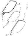
- Figure 3 shows a view of the lens assembly 100 and part of the eyeglasses frame 300 of the present invention.
- the view is from the rear of the lens, that is, from the normal viewing direction through the lens. Only the part of the eyeglasses frame around the lens is shown in the figure.
- the figure includes part of the bridge 308 of the eyeglasses frame to be supported on the nose of the user and part of the arm or temples 305 of the eyeglasses frame.
- the lens includes adjuster or dial 150 for adjusting the optical power of the lens.
- the dial or adjuster 150 is conveniently positioned behind the endpiece 306 of the frame that is at the side of the frame extending from the lens to where the arm or temple is attached.
- the dial or adjuster 150 forms part of the lens or lens assembly 100.
- the lens fits into and is held by an eyewire or rim 310 which forms part of the eyeglasses frame.
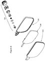
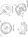
- Figure 4 shows three components of the lens 100. These are the first lens plate 110, second lens plate 120 and cover 130.
- the first lens plate is at the front or outside, and in use would be furthest from the pupil.
- the second lens plate 120 is in the middle between the first lens plate and cover.
- the cover is at the back, closest to the pupil.
- the cover maybe a simple flat plate or may be curved but with little or no fixed optical power.
- the first and second lens plates include the Alvarez surfaces.
- the form of any of the surfaces of the first and second lens plates may also include an additional contribution to the form which may provide no or a fixed optical power in addition to the variable power provided by the Alvarez forms.
- the front lens plate may include a piano or zero power, a spherical, aspheric or freeform optical outer surface, and the Alvarez surface as the inner surface.
- the second lens plate or middle lens comprises the Alvarez surface outer most from the user's pupil, that is, facing the Alvarez surface of the front lens plate.
- the middle lens may have a spherical or aspheric optical surface facing the user.
- the front lens plate 110 and rear cover 130 have a wall around their peripheries which when joined together form a cavity between the front lens and rear cover.
- Other arrangements of peripheral wall are possible, including forming the wall solely on the front lens or rear cover and mating that lens against the other of the front lens and rear cover.
- the peripheral wall may be a separate component assembled between the front lens plate and rear cover. Whichever arrangement of wall is chosen the wall seals the cavity between one of the lens plates and cover.
- the two lens plates having the Alvarez forms may be arranged as middle lens and rear lens plate, with the cover at the front, outermost from the pupil.
- the Alvarez surface of the two lens plates may be positioned such that one forms an outside surface of the lens assembly.
- the lens includes projection 140 in which a drive element 141 for translating the middle lens is housed.
- the projection is sealed to the atmosphere also by a peripheral wall.
- the adjuster or dial extends from the projection. Internally part of the dial interacts with the drive element 141.
- the drive element may be straight or curved so as to move the middle lens along a straight or curved path. For example, it may be advantageous to have a slightly curved or partially flexible drive element so as to move the middle lens along a curvilinear path within the optical cavity.
- a seal is provided between the drive element and dial.
- the seals prevent moisture or dirt from entering the cavity. If moisture gets into the cavity this may cause the internal surfaces to mist or steam up when the lens experiences changes in temperature. Any dirt entering the cavity will be difficult to remove so the seal is important in preventing its entry.
- Figures 5a and 5b provide more detail regarding the formation of the lens.
- Figure 5a relates to the front lens and figure 5b relates to the middle lens.
- Figure 5d relates to the rear cover.
- the front lens may comprise a bevel that locates in the eyewire or rim of the frame.
- the bevel may be formed as part of the rear cover or a combination of the rear cover and front lens.
- the front lens also includes a peripheral wall which locates to a corresponding peripheral wall of the rear cover.
- the peripheral wall may include a guidance feature 114 which is shown in detail E of figure 5a .
- the guidance feature guides translation of the middle lens.
- the guidance feature may be a channel cut into the peripheral wall.
- Figure 5a shows a channel cut into the inside of the top peripheral wall.
- the channel does not penetrate through the wall so as not to affect the cavity seal.
- the bottom peripheral wall may also include a channel.
- Figure 5b shows the middle lens including matching or cooperating guidance features. These may take the form of guidance lugs 116 as shown in detail C of figure 5b .
- the guidance lugs locate and move in the guidance channels 114 of the front lens.
- the guidance lugs and channels in combination maintain the orientation of the middle lens within the cavity such that the lens is maintained orthogonal to the optical axis.
- Details A and B on the middle lens are shown in figure 5b . These details include stabilisation bumps or dots 118 which are small round raised portions at the edge of the lens.
- the inside of the cavity may be provided with rails to guide the movement of the middle lens.
- Surfaces within the cavity may be provided with low-friction surfaces to aid movement on the middle lens plate. These surfaces may use coating, low-friction inserts, surface finishes or low-friction materials.
- the low-friction surfaces may be used within the adjustment protrusion on the peripheral wall of at the edge of the middle lens. Lubrication may also be used. Edge surfaces of the middle lens may also, or alternatively, be provided with low friction surfaces or lubrication.
- the embodiment of figure 5b shows the drive element 141 of the middle lens in more detail.
- the drive element includes a projection extending laterally from the lens.
- the projection includes teeth to form a rack.
- the rack may be driven by a pinion gear.
- the axis of rotation of the pinion gear is substantially parallel to the optical axis but offset therefrom.
- the lateral projection may include a worm for driving by a worm gear.
- the axis of rotation of the worm gear is substantially perpendicular to the optical axis.
- the pinion gear or worm gear is coupled to a shaft driven by a dial operated by the user.
- Other alternative drive arrangements include a flexible rack or chain section which can wrap around a pinion gear. A flexible rack or chain would result in shorter lateral adjustment projection.
- a gearbox may be included to increase or decrease the number of turns required for a given change in optical power.
- Figure 5c shows a cross-section vertically through the assembled lens.
- Figure 5d shows detail of the rear cover.
- the rear cover 130 and front lens plate 110 include peripheral walls 124 that meet together to form a cavity.
- the wall of the rear cover and that of the front lens may include complementary locating stepped portions which mate together and provide self-alignment of the two parts.
- Front lens and rear cover can be welded, bonded or otherwise joined where they meet.
- the middle lens plate can be seen between the front lens plate and rear cover.
- Figure 5d shows more detail of the rear side of the rear cover, that is, the side closest to the user's pupil.
- the lateral projection includes a circular collar in which will be sited the adjuster components including dial.
- the dial and adjuster extend from the collar. More detail regarding the collar is given below in the description of the adjuster.
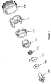
- Figure 6 is an exploded view of the lens 100 and adjuster 150.
- Figure 7 is a further exploded view showing more detail of the components of the adjuster.
- the adjuster shown is an exemplary embodiment. Other arrangements and configurations are possible. For example, components may be combined to reduce the number of components in the assembly.
- the adjuster comprises eight components, namely shaft 160, o-ring 162, membrane 164, compression spring 166, bearing 168, seal cap 170, dial clip 172 and dial 174.
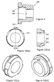
- Figure 8 shows further detail of the shaft 160.
- Figure 8 includes six view of the shaft.
- Figure 8a is an end view of the pinion gear end of the shaft, which indicates the positions of two cross-sections A and B. Section A is shown in figure 8b . Section B is shown in figure 8d.
- Figure 8c is an end view of the distal end to the pinion gear and shows the ends of fingers 182 for mating with corresponding features on the dial clip for rotational driving of the shaft.
- Figures 8e and 8f are perspective views of the shaft from different viewpoints.
- Shaft 160 includes pinion gear 183 for meshing with teeth of rack of drive element 141 of the middle lens.
- the end of the shaft includes a locating pin 184 which locates in a corresponding hole or recess in the lateral projection of the front lens to set the axis of rotation of the shaft.
- Shaft 160 includes a dividing flange 181 which may be a disc axially mounted part way along the shaft.
- the flange may be a circular or other shaped disc.
- On the shaft to one side of the disc flange are located driving features for driving movement of the lens.
- the other side of the flange are sealing and external drive components.
- the flange provides a surface against which a seal between the inside cavity between the lens plates and the external environment is provided.
- the seal may be provided by one or more components.
- the seal is provided by two sealing components with one of the sealing components biased against flange 181 by a spring.
- the components are shown in figure 7 as o-ring 162, membrane 164 and compression spring 166.
- the spring 166 is held in position by bearing 168 which includes a cup feature.
- the o-ring is fitted onto shaft and seals around shaft.
- the membrane is annular in shape and fits against the o-ring.
- the membrane and o-ring are biased towards the flange by the spring.
- the o-ring sits against the flange. Hence, the o-ring is in contact with the flange and shaft and seals against these two surfaces.
- the membrane 164 is made of a flexible impermeable material such as POM, PET or TPE and may have gasket-like properties.
- the membrane has a circular aperture so as to fit over the shaft.
- Figure 12 shows how the components of the adjuster 150 fit together.
- Figure 12b is a cross-section of the adjuster taken through the line indicated "B" in figure 12a .
- the membrane outer edge is constrained between the bearing 168 and a lip in the inside of the rear cover.
- Compression spring 166 pushes against the membrane urging it against o-ring 162.
- the membrane is positioned on the opposite side of the o-ring to the shaft flange 181 such that the biased membrane pushes the o-ring against the flange.
- the membrane may be coated with a sealing and/or lubricating grease.
- the compression spring fits over the shaft and is concentrically constrained by the shaft.
- Bearing 168 has an internal cup shape which retains the spring and constrains it in the axial direction. The spring pushes against the inside of the bearing cup at one end and urges the membrane towards the o-ring at the other end.
- the compression spring may be replaced by a biasing or lever arrangement which is integral to the bearing.
- the compression spring is selected to have characteristics such that the force exerted on the membrane by the compression spring equals the force exerted by air trapped within the lens cavity at its highest expected in-service pressure.
- the membrane and o-ring may be formed as a single component.
- This component would be annular when viewed in plan view but would have a cross-section of varying thickness, such as a pear or teardrop-shape.
- the inner part of the annulus has a thicker, almost circular cross-section similar to the o-ring and the outer part is flat similar to the membrane.
- Other variations on the shape of a seal part taking the place of the o-ring and membrane are possible.
- the bearing 168 is shown in more detail in figure 9 , where the above-mentioned cup-like shape can be seen.
- the bearing has a central aperture 189 through into which the shaft extends.
- the cup-like shape is formed by the aperture having a wider diameter section to house the compression spring which adjoins the narrower part by a step in the inner cylindrical wall.
- the compression spring sits in an annulus between the shaft and the wider diameter section of aperture of the bearing.
- the cup-like shape is further provided by lip 187 protruding from the top of wall 188. Bearing cup lip 187 pushes against membrane 164 constraining the outer part of the membrane.
- the annular space in which the compression spring sits may be filled with a sealing and/or lubricating grease.
- seal cap 170 and membrane 164 are formed as one part. This combined membrane cap fits within a substantially similar annular space.
- the bearing for such an embodiment is substantially similar to that described above, except for no longer requiring a lip 187 because the membrane is held in place by the seal cap.
- Figure 10 shows four views of seal cap 170.
- Figure 10a is a top plan view of the seal cap.
- Figure 10b is a sectional view through a diameter of the cap along the line "A" in figure 10a.
- Figures 10c and 10d are perspective views of the seal cap. In figure 10c the view is from the top and in figure 10d the view is from the underside.
- the seal cap is annular in shape. The seal cap constrains the bearing in position thereby keeping the compression spring, membrane and o-ring in position along the shaft. Like the bearing the seal cap does not rotate when the dial and shaft are rotated. The edge of the lip 187 of the bearing pushes against the inside of the collar of the rear cover 130. As a result of this the bearing determines the concentric alignment of the seal cap, shaft and compression spring.
- the bearing fits into a central aperture in the seal cap.
- the seal cap may be held in place by an adhesive or ultrasonic bond to the collar of the rear cover.
- seal cap 170 and membrane 164 forming a single part may be made from ABS or some other material that can be joined to the rest of the structure and is tough enough yet provides flex for the membrane application. Advantages to this combination part over the separate parts are a reduction in the number of potential leak paths, a reduction in part count and simplification of assembly.
- this alternative embodiment requires that the bearing 168 loses its lip 187 as it is simply pushed into a receiving cavity within the combined cap membrane component.
- This method of assembling the bearing 168 into the seal cap 170 means some sort of closure or constraining geometry is needed to prevent the spring 166 pushing it out again.
- Constraining geometry can be implemented through one or more features such as crush ribs, swaging features, heat staking features, etc. or even a separate component (sub-optimal but possible).
- a preferred way of overcoming this problem is to use an ultrasonic welding stage to melt swaging features on the seal cap 170 over the bearing 168, so we are in a very similar mode of operation to the embodiment of the figures.
- Glue is also possible, but is less preferred due to preferred bearing materials not being compatible with adhesives.
- An alternative method of locating the bearing in this embodiment would be over- or co-moulding of the seal cap over the bearing inside a mould tool.
- the seal cap outer edge may include lead-in or bevel regions 191. Three such regions are shown in figure 10 but other numbers may be used.
- the bevel regions allow the dial clip 172 to be easily pushed and snap fitted over the seal cap. This will be described more below in relation to the dial clip. These regions may be of different sizes and receive appropriately size matched features on the dial clip such that the dial clip is correctly orientated.
- the seal cap also comprises undercut 195 all around the peripheral underside edge which further enables snap fit.
- the seal cap may also comprise one or more alignment features. These are often known as poka yoke features 193 and prevent parts being incorrectly assembled because the alignment features permit assembly in a single orientation only.
- the poka yoke features may include lips, flats, tabs, holes, slots, protrusions etc.
- the poka yoke feature 193 is a slot which receives protrusion 194 of collar 126 as shown in figure 5d . This permits only one orientation for fitting the seal cap to the collar.
- the undercut and snap fit face allow elimination of flash or other moulding witness features on geometry on which the dial clip must rotate resulting in smoother actuation.
- Figure 11 shows four views of the dial clip 172.
- Figure 11a is a plan view of the underside.
- Figure 11b is a plan view from above of detail "A", which is a central portion of figure 11a.
- Figure 11c is a plan view from the side.
- Figure 11d is a perspective view of the underside.
- the dial clip has axle features which in the embodiment of figure 11 are fingers 197. These fingers 197 interface with the spaces between fingers 182 of shaft. The number of fingers is the same as the number of spaces between the fingers of the shaft. When assembled the fingers 197 of the dial clip preferably do not fill the depth of the spaces between the fingers 182 of the shaft. Similarly the fingers 182 of the shaft do not fill the depth of the spaces between the fingers of the dial clip 172.
- the resultant axial offset is a buffer to prevent shock or impact to the dial or dial clip from damaging or breaking the fingers, and may act as a buffer preventing the shock or impact been communicated all through the adjuster causing internal damage.
- the tips of the fingers of the dial clip (and/or the shaft) may include one or more chamfers so that during assembly the fingers of the dial clip are self-aligned (lead-in) to the spaces between the fingers of the shaft.
- each finger of the dial clip has a chamfer 198.
- interfaces other than fingers may be used between the shaft and dial clip.
- end of a shaft of the dial clip may abut and be screwed to the end of the shaft 160, or a keyway may be used.
- the dial clip includes a number of tines or prongs 203 extending from the face of the dial clip. These tines interface with the lead-in or bevel regions 191 of the dial clip. Hence, the number and spacing of the tines 203 matches that of the bevel regions 191. In figure 11 , there are three tines 203. As can be seen in figures 10 and 11a the spacing and size of each of the tines and bevel regions may not be the same. In the embodiment of figure 11a the tine at the top left of the figure is wider than the other two tines. This wider tine interfaces with the wider bevel region at the top right of figure 10a . This acts as a poka yoke feature for assembly in a single orientation or position.
- barbs 201 are formed of an undercut in the tine.
- the barbs facing inwards towards the axis of the dial clip.
- the chamfered part of the barb slides against the bevel regions 191 thereby pushing the tines slightly open. Further pushing of the dial clip towards the seal cap results in the barbs sliding over the lip at the edge of the dial clip.
- the step part of the barb 201 is now located beyond the lip preventing removal of the dial clip.
- the bevel or lead-in regions 191 are advantageous as they ease the tines over the lip without causing excessive strain or bending to the tines which could result in damage to them.
- the barbs snap fit to the seal cap.
- the inner diameter across the underside of the dial clip between the tines is sized so as to have an interference fit with the outer of the seal cap.
- the interference fit is to eliminate rattle during adjustment and normal wear.
- the interference fit also acts as a brake on unwanted accidental rotation.
- the dial clip includes a stop 205.
- the stop is not essential.
- the stop 205 is comprised of a further tine or elongation of one the tines 205.
- the stop 205 is an elongation of part of one of the tines.
- Protrusion 196 on the outside of the collar limits rotation the dial clip.
- the single protrusion shown allows a single rotation of the dial clip only. Smaller amounts of rotation can be limited by use of two protrusions extending from the collar at different circumferential positions.
- the stop 205 and protrusion 196 features prevent excessive rotation of the dial to protect the middle lens from excessive movement. Stops may be implemented by other features. For example, one or more projections may be provided running in complementary grooves with end limits.
- a clutch may be built into the adjuster instead of the stops to prevent over-turning of the dial.
- the dial 174 fits over the dial clip to form an easily rotatable feature.
- the dial is also cosmetic or aesthetic.
- the dial 174 is shown in figure 7 and figure 12b .
- the dial shown is a cylindrical cup-shape, having features on the sides of the cup to aid grip and rotation by fingers. These features may be grooves as shown, knurling, or a tactile material.
- the dial may include an alignment feature to fit the dial to the dial clip in correct alignment. The same feature or another feature may be used to hold the dial to the dial clip.
- the dial is located on to dial clip by peg 174 on dial which fits into hole 176 in the dial clip. One or a plurality of pegs and holes may be used.
- dial clip shown in figure 11 includes 3 holes, one adjacent to each tine.
- these holes also aid flexibility of the tines for the snap-fit.
- the pegs and holes may be differently sized such that the dial fits onto the dial clip in one orientation only. If the dial and dial clip have a single orientation of fixing together, the dial may be provided with a marker to allow the user to set the power of the lens by the rotational position of the dial.
- the dial and adjuster may also incorporate a tactile or audible feedback system to inform the user to the amount of rotation. This may for example be by a clicking sound or feel as the dial is rotated.
- dial and dial clip may be formed as a single component. In such as case, this may be by over-moulding or co-moulding of the dial to the dial clip.
- figure 12b shows a cross-section through the assembled adjuster.
- the bearing 168, shaft 160, spring 166, membrane 164 and o-ring 162 fit together.
- the fitting of two fingers 197 of the dial clip through the central aperture 189 in the bearing and to the shaft 160 is clearly shown.
- the dial is fitted to dial clip by peg 175 into hole 176.
- the cross-section taken mean that other pegs and holes are not shown.
- bearing and seal cap could be formed as a single part, as could be other combinations of parts in the adjuster.
- Figure 3 shows part of the eyeglasses frame and adjustable power lens according to the present invention.
- Eyeglasses frames conventionally mount a lens for each eye and fit to the face by a bridge which fits over the user's nose and temples or arms which fit over the user's ears.
- Figure 3 shows part of the bridge 308, one the lenses 100 mounted in the frame 300 and part of one of the temples or arms 305.
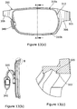
- the eyeglasses frame is also shown in plan view in figure 13a , without the lens and adjuster 150.
- the endpiece 306 hides the adjuster.
- Figure 3 is directed to metal frames, in which case eyewires 310 hold the lens in the frame.
- a rim holds the lens in place.
- the term rim can also be applied to metal frames.
- Some metal or plastic frames can appear to be partly rimless, such as semi-rimless frames which appear to only have a rim around the upper half of the lens.
- a narrow wire or plastic cord is used to secure the bottom of the lens.
- eyewire is applicable.
- the lens would include a groove in which the wire sits instead of having a bevel around the edge of the lens.
- Figure 13a is a plan view of the frame part shown in figure 3 without lens and adjuster.
- Figure 13b is a cross-sectional view along line A in figure 13a also without the lens mounted therein.
- Figure 13c is a detailed view of the groove in the eyewire 310a circled "B" in figure 13b .
- Figure 14 is a perspective view of the part of the frame shown in figure 13a without lens and adjuster.
- two eyewires 310a and 310b are shown for holding a lens. The two eyewires are secured together as they would be when holding the lens.
- the eyewires 310a, 310b are not coupled together.
- Figures 13b and 13c show groove 320 in receipt of bevel 322 around edge of lens.
- Conventionally such groove-bevel arrangements completely encircle the lens.
- the groove is formed in the eyewire of the frame.
- the groove is in the plastic rim of the frame which closes around the lens.
- the frame or eyewire closes around the lens at the endpiece 306 of the frame and is fixedly closed by a screw coupling the two sides of the rim or eyewire together.
- the frames according to the present invention must have a gap in the eyewire. This presents a problem because a gap in a conventional eyewire would result in release of the lens from the frame.
- a gap 312 is provided in the rim or eyewire at the endpiece of the frame.
- Comparison of figure 14 with figure 3 shows the lateral projection 140 and adjuster extending through the gap 312 when a lens of the present invention is fitted to the frame.
- the embodiment of figure 14 shows an upper portion 310a of the eyewire and a lower portion 310b of the eyewire.
- the frame comprises a frame front 330 which is the front part of the frame and most visible when the frames are worn by the user.
- the bridge 308 and endpiece 306 are formed by the frame front.
- the endpiece 306 meets the temple at its distal end.
- the frame may comprise nose pads 340. The frame rests on the nose at the nose pad and may hold the bridge of the frame above the nose.
- figure 14 shows the eyewire formed of upper portion 310a and lower portion 310b.
- the upper portion 310 is preferably rigidly fixed to the frame front in a position to match the perimeter shape of the upper portion of the lens.
- the upper eyewire 310a may be fixed to the frame front towards its two ends or may be fixed at any number of points or may form a continuous join along the length of the upper eyewire. The fixing may be by welding, gluing or other means.
- the upper eyewire is spaced apart from the lower eyewire forming gap 312 to accommodate the lens lateral projection and adjuster.
- the lower eyewire 310b is fixedly coupled to the frame front at the endpiece. The other end of the lower eyewire is not fixed to the frame.
- the lower eyewire is flexible because of its limited fixing to the frame.
- the flexibility of the lower eyewire allows the eyewire to be opened for insertion of the lens.
- the end of the lower eyewire 310b adjacent to the bridge and distal to the endpiece is coupled to the upper wire 310a using a fastener such as a screw, bolt etc.
- the upper and lower eyewires have a screw boss fixed to it. One has a thread for receiving screw and the other has a hole through which the screw can pass to engage to the threaded portion in the other boss. By screwing the screw bosses together the upper and lower eyewires close against each other to hold the lens in place. The grooves in the closing eyewires pull tight around the bevel of the lens keeping it in position.
- the upper eyewire may be fixed to the frame along only part of its length but sufficient to securely hold the lens relative to the frame.
- the screw boss 325 of fixed upper eyewire 310a provides the mounting point for nose pad 340.
- This is a convenient mounting point hidden behind the frame front but remaining in a fixed position even when the lower eyewire is released.
- the nose pad can be coupled to the frame front or bridge of the frame.
- the lens is shown to have the bevel and the eyewires are shown to have the groove.
- the lens may have the groove and the eyewires may include the bevel.
- a groove and bevel or other locating features are required to constrain the lens in position in the frame.
- the gap in the eyewires is positioned at the endpiece and the endpiece bridges the across the gap.
- the endpiece location of adjuster provides a convenient position for the adjuster for access at the sides of the eyeglasses.
- the endpiece may also hide the adjuster.
- the gap is at the endpiece and it could be located elsewhere such as at the bridge.
- the position where the eyewires are coupled together, such as by fastener may not be adjacent to the bridge. It must be at a different position compared to the gap.
- the eyewires could for example couple together at point such as above the centre of the lens.
- the lower eyewire would also extend around along half of the length along the top of the lens.
- the upper eyewire would be around half the length of that shown in figure 14 .
- the eyewires arranged of approximately equal lengths and arranged as an upper half and lower half in that it provides good access for attaching the lens.
- the gap 312a for receiving the adjuster and lateral protrusion and the break in the eyewire for insertion of the lens into the frame are both located at the endpiece of the frame.
- the fastener coupling 325a is located behind the endpiece.
- the gap in the eyewire for 312a is slightly larger than that in figure so as that the fastener coupling can be accommodated.
- the break in the eyewire for insertion of the lens into the frame is shown as split or cut in the eyewire and/or frame at 350. Similar to the above-described embodiment there is a first first break in the eyewire 312a to allow the adjuster protrusion to sit directly behind the frame at the temple.
- the second break in the eyewire that allows the eyewire to open up to accept the lens now extends through the frame itself so that the entire frame opens up to accept the lens. In the above embodiments only the eyewire has as split and not the frame.
- FIG 16 A further alternative arrangement based on figure 14 is shown in figure 16 .
- the nose pad is not shown but could be coupled to the eyewire or bridge.
- the frame front itself is reduced such that it is formed of the bridge and endpiece. Between these the frame has been removed.
- the eyewires remain for holding the lens.
- the combination of lens and eyewires provides strength to keep the eyeglasses rigid.
- the removal of the frame front between the endpiece and bridge provides a lighter appearance to the frames.
- plastic frames for mounting the lens of the present invention which includes lateral projection and adjuster.
- the groove is formed in the frame itself, such as in the rim.
- a gap in the groove is again formed to allow the lens protrusion to extend past the groove.
- the gap is part of a pocket formed at the temple of the frame that at least partly conceals the lateral projection when viewed from the front.
- the mounting of the lens may be accomplished by softening the rim of the frame, inserting the lens, and re-hardening the rim.
- the lens may be snap-fit such that the lens bevel snap-fits into the groove of the rim.
- plastic frames are to incorporate one or more break points in the rim which can be opened up for insertion of the lens.
- the break points may be joined together by snap-fit, interference fit or a mechanical fastener.
- a further alternative to the above securing methods is to secure the lens to the frame using adhesive bonding, welding, heat staking or fasteners. These methods are applicable to metal or plastic frames.
- the lens may be mounted using anchor points instead of the groove-bevel features discussed above.
- This arrangement might be used for rimless type eyeglasses frames.
- the lens is coupled directly to the endpiece or temples and bridge by direction mounting of them to the optical surfaces.
- the anchor points must clear the adjuster and not interfere with the movement of the middle lens. In this regard they could be fixed to the front lens only or rear cover only, or pass through the whole lens assembly but sealed to the assembly.
- the anchor points may also take the form of tabs or projections extending from the lens.
Landscapes
- Physics & Mathematics (AREA)
- General Physics & Mathematics (AREA)
- Optics & Photonics (AREA)
- Health & Medical Sciences (AREA)
- Ophthalmology & Optometry (AREA)
- General Health & Medical Sciences (AREA)
- Eyeglasses (AREA)
Claims (16)
- Linse (100), deren optische Kraft durch relative seitliche Verlagerung von zwei Linsenelementen einstellbar ist, wobei die Linse aufweist:ein erstes Linsenelement (110), das zu einer Abdeckung (130) versiegelt ist, um dazwischen einen Hohlraum zu definieren;ein zweites Linsenelement (120), das in dem Hohlraum angeordnet und mit einem länglichen Antriebselement (141) gekoppelt ist, das sich von dem zweiten Linsenelement seitlich erstreckt, wobei das zweite Linsenelement so angeordnet ist, dass es relativ zu dem ersten Linsenelement durch seitliche Verlagerung des länglichen Antriebselements seitlich anzutreiben ist, um hierdurch die optische Kraft der Linse einzustellen,wobei die Linse einen Einsteller (150) zum Antrieb der seitlichen Verlagerung des länglichen Antriebselements aufweist,wobei die Linse ferner dadurch gekennzeichnet ist, dass sie einen seitlichen Vorsprung (140) aufweist, in den sich der Hohlraum und das Antriebselement erstrecken, wobei an dem seitlichen Vorsprung der Einsteller angebracht ist, wobei der Einsteller ein Dreheinsteller ist, der vom Benutzer drehbar ist, um die optische Kraft der Linse zu steuern.
- Die Linse von Anspruch 1, wobei der seitliche Vorsprung zumindest teilweise durch einen Vorsprung des ersten Linsenelements und/oder der Abdeckung vorgesehen ist.
- Die Linse von Anspruch 1, wobei der seitliche Vorsprung einen abgedeckten Kanal aufweist, in dem das längliche Antriebselement angeordnet ist, um den sich von dem abgedeckten Kanal erstreckenden Einsteller zu bewegen.
- Die Linse nach einem vorhergehenden Anspruch, die ein Paar von Alvarez- oder Alvarez-artigen Linsenplatten aufweist,
wobei das erste Linsenelement (110) zumindest ein Teil der ersten der Alvarez- oder Alvarez-artigen Linsenplatten bildet, und
das zweite Linsenelement (120) zumindest ein Teil der zweiten der Alvarez- oder Alvarez-artigen Linsenplatten bildet. - Die Linse von Anspruch 1, wobei der Dreheinsteller (150) eine Welle (160) aufweist und der Hohlraum durch eine Dichtung versiegelt ist, die zwischen dem seitlichen Vorsprung und der Welle vorgesehen ist.
- Die Linse von Anspruch 5, wobei die Welle einen Dichtungsflansch (181) aufweist, wobei an der einen Seite des Dichtungsflanschs der Dreheinsteller angeordnet ist, um das längliche Antriebselement zu betätigen, und an der anderen Seite des Dichtungsflanschs eine Dichtung zwischen dem seitlichen Vorsprung und der Welle angeordnet ist,
wobei der Dichtungsflansch die seitliche Verlagerung des länglichen Antriebselements führt. - Die Linse von Anspruch 5 oder 6, wobei eine Dichtung um den Dreheinsteller herum eine vorgespannte Membran und/oder einen elastischen Ring aufweist, und wobei die Dichtung gegen eine Dichtungsfläche abdichtet, die durch die Welle und/oder den Dichtungsflansch vorgesehen ist,und optionaldie Membran gegen den seitlichen Vorsprung durch eine Lagerkappe geschichtet ist, wobei die Lagerkappe Vorspannmittel aufnimmt, um die Dichtung vorzuspannen, und der Dreheinsteller ein Einstellrad aufweist, das sich innerhalb einer Öffnung in der Lagerkappe zu der Welle hin erstreckt, wobei das Einstellrad angeordnet ist, um die Welle drehend anzutreiben.
- Die Linse von einem vorhergehenden Anspruch, wobei:das längliche Antriebselement und der Dreheinsteller Zahnstange und Ritzel aufweisen, und optional die Drehachse des Dreheinstellers quer zur Richtung der seitlichen Verlagerung ist, oderdas längliche Antriebselement und der Dreheinsteller einen Schneckenantrieb aufweisen, und die Drehachse des Dreheinstellers quer zur optischen Achse der Linse ist.
- Die Linse von Anspruch 8, wobei das längliche Antriebselement und der Dreheinsteller Zahnstange und Ritzel aufweisen, und wobei die Zahnstange flexibel ist.
- Korrekturbrille, die eine oder zwei Linsen nach einem vorhergehenden Anspruch aufweist, wobei der Einsteller hinter Endstücken des Rahmens versteckt ist, wenn er von einem Benutzer getragen wird.
- Korrekturbrille, die die Linse von einem der Ansprüche 1 bis 9 und einen Brillenrahmen (300) aufweist, wobei der Rahmen aufweist:
ein Paar von Rändern oder Brillendrähten (310a, 310b), die jeweils eine Nut (320) aufweisen, die angeordnet ist, um die Linse zu umschließen und zu halten, wobei, wenn die Linse umschlossen ist, jede Nut eine Lücke (312; 312a) aufweist, um den seitlichen Vorsprung (140) der Linse mit einstellbarer optischer Kraft aufzunehmen. - Die Korrekturbrille von Anspruch 11, wobei die Lücke (312; 312a) an dem Endstück (306) des Rahmens vorgesehen ist.
- Die Korrekturbrille von Anspruch 11 oder 12, wobei die Rahmenvorderseite die Lücke in der Nut überspannt.
- Die Korrekturbrille von einem der Ansprüche 11 bis 13, wobei jeder Rand oder Brillendraht Enden aufweist, die angeordnet sind, um durch ein Befestigungselement miteinander gekoppelt zu werden, um den Linsenrand zu umschließen, und beim Lösen des Befestigungselements der Rand flexibel ist, um die Linse einzusetzen.
- Die Korrekturbrille von Anspruch 14, wobei die Befestigungskupplung proximal zur Brücke oder zum Nasenpolster ist, und die Befestigungskupplung mit dem Nasenpolster oder dessen Verbindung mit dem Rand oder der Rahmenfront integriert ist, oder
wobei die Befestigungskupplung an dem Endstück des Rahmens ist und die Befestigungskupplung zur Rahmenfront koppelt. - Die Korrekturbrille von einem der Ansprüche 11 bis 15, wobei die Nuten mit dem Rahmen integriert sind, und der Rahmen benachbart der Lücke in der Nut eine vertiefte Tasche aufweist, um den Einsteller der Linse mit einstellbarer optischer Kraft aufzunehmen.
Applications Claiming Priority (2)
| Application Number | Priority Date | Filing Date | Title |
|---|---|---|---|
| GB1414965.2A GB2529477A (en) | 2014-08-22 | 2014-08-22 | Adjustable power lens and eyeglasses frame |
| PCT/GB2015/052420 WO2016027093A1 (en) | 2014-08-22 | 2015-08-20 | Adjustable power lens and eyeglasses frame |
Publications (2)
| Publication Number | Publication Date |
|---|---|
| EP3195050A1 EP3195050A1 (de) | 2017-07-26 |
| EP3195050B1 true EP3195050B1 (de) | 2018-07-04 |
Family
ID=51726959
Family Applications (1)
| Application Number | Title | Priority Date | Filing Date |
|---|---|---|---|
| EP15756220.8A Active EP3195050B1 (de) | 2014-08-22 | 2015-08-20 | Linse mit einstellbarer leistung und brillenfassung |
Country Status (4)
| Country | Link |
|---|---|
| US (1) | US10302967B2 (de) |
| EP (1) | EP3195050B1 (de) |
| GB (1) | GB2529477A (de) |
| WO (1) | WO2016027093A1 (de) |
Cited By (1)
| Publication number | Priority date | Publication date | Assignee | Title |
|---|---|---|---|---|
| DE102019129445A1 (de) * | 2019-10-31 | 2021-05-06 | Carl Zeiss Jena Gmbh | Gemeinsame Führung beweglicher optischer Elemente |
Families Citing this family (8)
| Publication number | Priority date | Publication date | Assignee | Title |
|---|---|---|---|---|
| US10663765B2 (en) | 2015-11-20 | 2020-05-26 | Santana L. Nottage | Customizable eyeglass system and method of use |
| US10670886B2 (en) | 2015-11-20 | 2020-06-02 | Santana L. Nottage | Customizable scope system and method of use |
| GB201603149D0 (en) * | 2016-02-22 | 2016-04-06 | Adlens Ltd | Improvements in or relating to glasses with selectively adjustable optical power lenses |
| ITUA20163093A1 (it) * | 2016-05-03 | 2017-11-03 | Luca Maresca | Strumento ottico reversibile |
| CN111399219A (zh) * | 2019-02-28 | 2020-07-10 | 南昌虚拟现实研究院股份有限公司 | 虚拟现实镜组、设备以及系统 |
| GB2618587A (en) * | 2022-05-11 | 2023-11-15 | Adlens Ltd | Improvements in or relating to the manufacture of adjustable focal length lenses |
| CN115826323B (zh) * | 2022-08-26 | 2025-08-26 | 合肥市商巨智能装备有限公司 | 一种检测相机的自动调焦系统 |
| CN115356854B (zh) * | 2022-10-19 | 2023-01-20 | 歌尔股份有限公司 | 智能眼镜 |
Family Cites Families (13)
| Publication number | Priority date | Publication date | Assignee | Title |
|---|---|---|---|---|
| US3305294A (en) | 1964-12-03 | 1967-02-21 | Optical Res & Dev Corp | Two-element variable-power spherical lens |
| FR2489003A2 (fr) * | 1979-10-16 | 1982-02-26 | Essilor Int | Monture de lunettes |
| US5499063A (en) * | 1994-04-25 | 1996-03-12 | Vision Express Group Limited | Multifocal trial frame system |
| US6966657B2 (en) * | 2004-02-19 | 2005-11-22 | Barco N.V. | Projection lens fixation and adjustment mechanism |
| US7079332B2 (en) * | 2004-06-21 | 2006-07-18 | Pentax Corporation | Lens tilt adjusting mechanism |
| US8197062B1 (en) * | 2008-03-19 | 2012-06-12 | Glenn Arthur Morrison | Varifical lens system for eyeglasses |
| GB2477264B (en) * | 2010-01-18 | 2015-02-25 | Gici Labs Llp | Eyeglasses and means for their adjustment |
| CN201853012U (zh) * | 2010-10-26 | 2011-06-01 | 澳加光学有限公司 | 一种双镜片眼镜 |
| GB2486212A (en) | 2010-12-06 | 2012-06-13 | Owen Reading | A self-contained variable power lens unit with enclosed laterally movable optical plate |
| GB201115124D0 (en) | 2011-09-01 | 2011-10-19 | Crosby David | Improved adjustable refractive optical device for context specific use |
| GB2498171A (en) * | 2011-11-03 | 2013-07-10 | Sas Self Adjustable Spectacles B V | Spectacles with laterally adjustable dual lenses to vary focal length |
| KR101420157B1 (ko) * | 2012-10-22 | 2014-07-17 | 주식회사 케이엠디피 | 렌즈의 초점 가변 장치 및 이를 구비한 안경 |
| GB201302719D0 (en) | 2013-02-15 | 2013-04-03 | Adlens Ltd | Variable-power lens |
-
2014
- 2014-08-22 GB GB1414965.2A patent/GB2529477A/en not_active Withdrawn
-
2015
- 2015-08-20 EP EP15756220.8A patent/EP3195050B1/de active Active
- 2015-08-20 US US15/504,849 patent/US10302967B2/en active Active
- 2015-08-20 WO PCT/GB2015/052420 patent/WO2016027093A1/en not_active Ceased
Non-Patent Citations (1)
| Title |
|---|
| None * |
Cited By (1)
| Publication number | Priority date | Publication date | Assignee | Title |
|---|---|---|---|---|
| DE102019129445A1 (de) * | 2019-10-31 | 2021-05-06 | Carl Zeiss Jena Gmbh | Gemeinsame Führung beweglicher optischer Elemente |
Also Published As
| Publication number | Publication date |
|---|---|
| GB2529477A (en) | 2016-02-24 |
| US20170242270A1 (en) | 2017-08-24 |
| US10302967B2 (en) | 2019-05-28 |
| EP3195050A1 (de) | 2017-07-26 |
| GB201414965D0 (en) | 2014-10-08 |
| WO2016027093A1 (en) | 2016-02-25 |
Similar Documents
| Publication | Publication Date | Title |
|---|---|---|
| EP3195050B1 (de) | Linse mit einstellbarer leistung und brillenfassung | |
| US8002403B2 (en) | Variable focus lens and spectacles | |
| US5526068A (en) | Optical plastic and glass lens assembly for use in an eyewear frame | |
| US9075247B2 (en) | Eyeglasses and means for their adjustment | |
| US6074059A (en) | Sunglasses with removable lenses | |
| EP1865363B1 (de) | Gelenksystem für Brillen | |
| JPS6115124A (ja) | 眼鏡のスプリング・ヒンジ | |
| US20090190089A1 (en) | Eyeglasses structure | |
| EP3350647B1 (de) | Rahmenverbindung und scharnier für brille | |
| US20140078461A1 (en) | Receptor and lock for glasses with removable lenses | |
| JP2000147436A (ja) | 眼鏡用のフルリムフレ―ムのセントラルピ―ス及び眼鏡のセントラルピ―スを製造する製造方法 | |
| US20220283447A1 (en) | Removable, interchangeable, unbreakable, screwless, one-piece flexible spring hinge system for eyewear | |
| EP3750006B1 (de) | Flexible brillenanordnung | |
| US20040046930A1 (en) | Configurable eyewear | |
| US5896186A (en) | Eyeglass assembly having pivotable receiving means | |
| US20230139609A1 (en) | Adjustable included angle of rotatable shaft assembly and terminal device | |
| WO1997016761A1 (en) | Magnetic eyewear system | |
| KR20040044134A (ko) | 향상된 안경-부착식 선그라스 | |
| US20010024262A1 (en) | Spectacle frame having rotatable temples | |
| JP2009092946A (ja) | 眼鏡フレームのバネ付勢式モダン角度調整機構 | |
| MX2013010903A (es) | Anteojos. | |
| JP2010085590A (ja) | 眼鏡のテンプル連結構造及び眼鏡フレーム | |
| JP3141598U (ja) | 眼鏡用テンプル構造 | |
| CN219245875U (zh) | 一种转动组件及眼镜 | |
| US20240061277A1 (en) | Glasses |
Legal Events
| Date | Code | Title | Description |
|---|---|---|---|
| PUAI | Public reference made under article 153(3) epc to a published international application that has entered the european phase |
Free format text: ORIGINAL CODE: 0009012 |
|
| 17P | Request for examination filed |
Effective date: 20170222 |
|
| AK | Designated contracting states |
Kind code of ref document: A1 Designated state(s): AL AT BE BG CH CY CZ DE DK EE ES FI FR GB GR HR HU IE IS IT LI LT LU LV MC MK MT NL NO PL PT RO RS SE SI SK SM TR |
|
| AX | Request for extension of the european patent |
Extension state: BA ME |
|
| DAV | Request for validation of the european patent (deleted) | ||
| DAX | Request for extension of the european patent (deleted) | ||
| RIC1 | Information provided on ipc code assigned before grant |
Ipc: G02B 7/02 20060101ALI20171128BHEP Ipc: G02C 1/08 20060101ALI20171128BHEP Ipc: G02C 5/00 20060101ALI20171128BHEP Ipc: G02C 7/08 20060101AFI20171128BHEP Ipc: G02C 1/00 20060101ALI20171128BHEP Ipc: G02B 27/00 20060101ALI20171128BHEP |
|
| GRAP | Despatch of communication of intention to grant a patent |
Free format text: ORIGINAL CODE: EPIDOSNIGR1 |
|
| INTG | Intention to grant announced |
Effective date: 20180118 |
|
| GRAS | Grant fee paid |
Free format text: ORIGINAL CODE: EPIDOSNIGR3 |
|
| GRAA | (expected) grant |
Free format text: ORIGINAL CODE: 0009210 |
|
| AK | Designated contracting states |
Kind code of ref document: B1 Designated state(s): AL AT BE BG CH CY CZ DE DK EE ES FI FR GB GR HR HU IE IS IT LI LT LU LV MC MK MT NL NO PL PT RO RS SE SI SK SM TR |
|
| REG | Reference to a national code |
Ref country code: GB Ref legal event code: FG4D |
|
| REG | Reference to a national code |
Ref country code: CH Ref legal event code: EP |
|
| REG | Reference to a national code |
Ref country code: AT Ref legal event code: REF Ref document number: 1015117 Country of ref document: AT Kind code of ref document: T Effective date: 20180715 |
|
| REG | Reference to a national code |
Ref country code: IE Ref legal event code: FG4D |
|
| REG | Reference to a national code |
Ref country code: DE Ref legal event code: R096 Ref document number: 602015013123 Country of ref document: DE |
|
| REG | Reference to a national code |
Ref country code: FR Ref legal event code: PLFP Year of fee payment: 4 Ref country code: NL Ref legal event code: FP |
|
| REG | Reference to a national code |
Ref country code: LT Ref legal event code: MG4D |
|
| REG | Reference to a national code |
Ref country code: AT Ref legal event code: MK05 Ref document number: 1015117 Country of ref document: AT Kind code of ref document: T Effective date: 20180704 |
|
| PG25 | Lapsed in a contracting state [announced via postgrant information from national office to epo] |
Ref country code: SE Free format text: LAPSE BECAUSE OF FAILURE TO SUBMIT A TRANSLATION OF THE DESCRIPTION OR TO PAY THE FEE WITHIN THE PRESCRIBED TIME-LIMIT Effective date: 20180704 Ref country code: CZ Free format text: LAPSE BECAUSE OF FAILURE TO SUBMIT A TRANSLATION OF THE DESCRIPTION OR TO PAY THE FEE WITHIN THE PRESCRIBED TIME-LIMIT Effective date: 20180704 Ref country code: AT Free format text: LAPSE BECAUSE OF FAILURE TO SUBMIT A TRANSLATION OF THE DESCRIPTION OR TO PAY THE FEE WITHIN THE PRESCRIBED TIME-LIMIT Effective date: 20180704 Ref country code: NO Free format text: LAPSE BECAUSE OF FAILURE TO SUBMIT A TRANSLATION OF THE DESCRIPTION OR TO PAY THE FEE WITHIN THE PRESCRIBED TIME-LIMIT Effective date: 20181004 Ref country code: BG Free format text: LAPSE BECAUSE OF FAILURE TO SUBMIT A TRANSLATION OF THE DESCRIPTION OR TO PAY THE FEE WITHIN THE PRESCRIBED TIME-LIMIT Effective date: 20181004 Ref country code: GR Free format text: LAPSE BECAUSE OF FAILURE TO SUBMIT A TRANSLATION OF THE DESCRIPTION OR TO PAY THE FEE WITHIN THE PRESCRIBED TIME-LIMIT Effective date: 20181005 Ref country code: LT Free format text: LAPSE BECAUSE OF FAILURE TO SUBMIT A TRANSLATION OF THE DESCRIPTION OR TO PAY THE FEE WITHIN THE PRESCRIBED TIME-LIMIT Effective date: 20180704 Ref country code: FI Free format text: LAPSE BECAUSE OF FAILURE TO SUBMIT A TRANSLATION OF THE DESCRIPTION OR TO PAY THE FEE WITHIN THE PRESCRIBED TIME-LIMIT Effective date: 20180704 Ref country code: RS Free format text: LAPSE BECAUSE OF FAILURE TO SUBMIT A TRANSLATION OF THE DESCRIPTION OR TO PAY THE FEE WITHIN THE PRESCRIBED TIME-LIMIT Effective date: 20180704 Ref country code: IS Free format text: LAPSE BECAUSE OF FAILURE TO SUBMIT A TRANSLATION OF THE DESCRIPTION OR TO PAY THE FEE WITHIN THE PRESCRIBED TIME-LIMIT Effective date: 20181104 Ref country code: PL Free format text: LAPSE BECAUSE OF FAILURE TO SUBMIT A TRANSLATION OF THE DESCRIPTION OR TO PAY THE FEE WITHIN THE PRESCRIBED TIME-LIMIT Effective date: 20180704 |
|
| PG25 | Lapsed in a contracting state [announced via postgrant information from national office to epo] |
Ref country code: ES Free format text: LAPSE BECAUSE OF FAILURE TO SUBMIT A TRANSLATION OF THE DESCRIPTION OR TO PAY THE FEE WITHIN THE PRESCRIBED TIME-LIMIT Effective date: 20180704 Ref country code: AL Free format text: LAPSE BECAUSE OF FAILURE TO SUBMIT A TRANSLATION OF THE DESCRIPTION OR TO PAY THE FEE WITHIN THE PRESCRIBED TIME-LIMIT Effective date: 20180704 Ref country code: LV Free format text: LAPSE BECAUSE OF FAILURE TO SUBMIT A TRANSLATION OF THE DESCRIPTION OR TO PAY THE FEE WITHIN THE PRESCRIBED TIME-LIMIT Effective date: 20180704 Ref country code: HR Free format text: LAPSE BECAUSE OF FAILURE TO SUBMIT A TRANSLATION OF THE DESCRIPTION OR TO PAY THE FEE WITHIN THE PRESCRIBED TIME-LIMIT Effective date: 20180704 |
|
| REG | Reference to a national code |
Ref country code: CH Ref legal event code: PL |
|
| REG | Reference to a national code |
Ref country code: DE Ref legal event code: R097 Ref document number: 602015013123 Country of ref document: DE |
|
| PG25 | Lapsed in a contracting state [announced via postgrant information from national office to epo] |
Ref country code: CH Free format text: LAPSE BECAUSE OF NON-PAYMENT OF DUE FEES Effective date: 20180831 Ref country code: LU Free format text: LAPSE BECAUSE OF NON-PAYMENT OF DUE FEES Effective date: 20180820 Ref country code: EE Free format text: LAPSE BECAUSE OF FAILURE TO SUBMIT A TRANSLATION OF THE DESCRIPTION OR TO PAY THE FEE WITHIN THE PRESCRIBED TIME-LIMIT Effective date: 20180704 Ref country code: LI Free format text: LAPSE BECAUSE OF NON-PAYMENT OF DUE FEES Effective date: 20180831 Ref country code: MC Free format text: LAPSE BECAUSE OF FAILURE TO SUBMIT A TRANSLATION OF THE DESCRIPTION OR TO PAY THE FEE WITHIN THE PRESCRIBED TIME-LIMIT Effective date: 20180704 Ref country code: IT Free format text: LAPSE BECAUSE OF FAILURE TO SUBMIT A TRANSLATION OF THE DESCRIPTION OR TO PAY THE FEE WITHIN THE PRESCRIBED TIME-LIMIT Effective date: 20180704 Ref country code: RO Free format text: LAPSE BECAUSE OF FAILURE TO SUBMIT A TRANSLATION OF THE DESCRIPTION OR TO PAY THE FEE WITHIN THE PRESCRIBED TIME-LIMIT Effective date: 20180704 |
|
| PLBE | No opposition filed within time limit |
Free format text: ORIGINAL CODE: 0009261 |
|
| REG | Reference to a national code |
Ref country code: BE Ref legal event code: MM Effective date: 20180831 |
|
| STAA | Information on the status of an ep patent application or granted ep patent |
Free format text: STATUS: NO OPPOSITION FILED WITHIN TIME LIMIT |
|
| REG | Reference to a national code |
Ref country code: IE Ref legal event code: MM4A |
|
| PG25 | Lapsed in a contracting state [announced via postgrant information from national office to epo] |
Ref country code: SK Free format text: LAPSE BECAUSE OF FAILURE TO SUBMIT A TRANSLATION OF THE DESCRIPTION OR TO PAY THE FEE WITHIN THE PRESCRIBED TIME-LIMIT Effective date: 20180704 Ref country code: DK Free format text: LAPSE BECAUSE OF FAILURE TO SUBMIT A TRANSLATION OF THE DESCRIPTION OR TO PAY THE FEE WITHIN THE PRESCRIBED TIME-LIMIT Effective date: 20180704 Ref country code: SM Free format text: LAPSE BECAUSE OF FAILURE TO SUBMIT A TRANSLATION OF THE DESCRIPTION OR TO PAY THE FEE WITHIN THE PRESCRIBED TIME-LIMIT Effective date: 20180704 |
|
| 26N | No opposition filed |
Effective date: 20190405 |
|
| PG25 | Lapsed in a contracting state [announced via postgrant information from national office to epo] |
Ref country code: IE Free format text: LAPSE BECAUSE OF NON-PAYMENT OF DUE FEES Effective date: 20180820 |
|
| PG25 | Lapsed in a contracting state [announced via postgrant information from national office to epo] |
Ref country code: SI Free format text: LAPSE BECAUSE OF FAILURE TO SUBMIT A TRANSLATION OF THE DESCRIPTION OR TO PAY THE FEE WITHIN THE PRESCRIBED TIME-LIMIT Effective date: 20180704 Ref country code: BE Free format text: LAPSE BECAUSE OF NON-PAYMENT OF DUE FEES Effective date: 20180831 |
|
| PG25 | Lapsed in a contracting state [announced via postgrant information from national office to epo] |
Ref country code: MT Free format text: LAPSE BECAUSE OF NON-PAYMENT OF DUE FEES Effective date: 20180820 |
|
| PG25 | Lapsed in a contracting state [announced via postgrant information from national office to epo] |
Ref country code: TR Free format text: LAPSE BECAUSE OF FAILURE TO SUBMIT A TRANSLATION OF THE DESCRIPTION OR TO PAY THE FEE WITHIN THE PRESCRIBED TIME-LIMIT Effective date: 20180704 |
|
| PG25 | Lapsed in a contracting state [announced via postgrant information from national office to epo] |
Ref country code: PT Free format text: LAPSE BECAUSE OF FAILURE TO SUBMIT A TRANSLATION OF THE DESCRIPTION OR TO PAY THE FEE WITHIN THE PRESCRIBED TIME-LIMIT Effective date: 20180704 |
|
| PG25 | Lapsed in a contracting state [announced via postgrant information from national office to epo] |
Ref country code: HU Free format text: LAPSE BECAUSE OF FAILURE TO SUBMIT A TRANSLATION OF THE DESCRIPTION OR TO PAY THE FEE WITHIN THE PRESCRIBED TIME-LIMIT; INVALID AB INITIO Effective date: 20150820 Ref country code: CY Free format text: LAPSE BECAUSE OF FAILURE TO SUBMIT A TRANSLATION OF THE DESCRIPTION OR TO PAY THE FEE WITHIN THE PRESCRIBED TIME-LIMIT Effective date: 20180704 Ref country code: MK Free format text: LAPSE BECAUSE OF NON-PAYMENT OF DUE FEES Effective date: 20180704 |
|
| PGFP | Annual fee paid to national office [announced via postgrant information from national office to epo] |
Ref country code: NL Payment date: 20240819 Year of fee payment: 10 |
|
| PGFP | Annual fee paid to national office [announced via postgrant information from national office to epo] |
Ref country code: DE Payment date: 20240821 Year of fee payment: 10 |
|
| PGFP | Annual fee paid to national office [announced via postgrant information from national office to epo] |
Ref country code: GB Payment date: 20240819 Year of fee payment: 10 |
|
| PGFP | Annual fee paid to national office [announced via postgrant information from national office to epo] |
Ref country code: FR Payment date: 20240819 Year of fee payment: 10 |
|
| REG | Reference to a national code |
Ref country code: DE Ref legal event code: R119 Ref document number: 602015013123 Country of ref document: DE |
|
| REG | Reference to a national code |
Ref country code: NL Ref legal event code: MM Effective date: 20250901 |