EP3194890B1 - Procédés et appareil de détermination de dépense d'énergie et de technique durant un mouvement des jambes - Google Patents
Procédés et appareil de détermination de dépense d'énergie et de technique durant un mouvement des jambes Download PDFInfo
- Publication number
- EP3194890B1 EP3194890B1 EP15841179.3A EP15841179A EP3194890B1 EP 3194890 B1 EP3194890 B1 EP 3194890B1 EP 15841179 A EP15841179 A EP 15841179A EP 3194890 B1 EP3194890 B1 EP 3194890B1
- Authority
- EP
- European Patent Office
- Prior art keywords
- user
- data
- processor
- axis motion
- motion data
- Prior art date
- Legal status (The legal status is an assumption and is not a legal conclusion. Google has not performed a legal analysis and makes no representation as to the accuracy of the status listed.)
- Active
Links
- 230000033001 locomotion Effects 0.000 title claims description 220
- 238000000034 method Methods 0.000 title claims description 95
- 238000005259 measurement Methods 0.000 claims description 57
- 230000001133 acceleration Effects 0.000 claims description 38
- 238000005070 sampling Methods 0.000 claims description 35
- 230000008859 change Effects 0.000 claims description 30
- 238000009826 distribution Methods 0.000 claims description 21
- 230000037081 physical activity Effects 0.000 claims description 13
- 230000002503 metabolic effect Effects 0.000 claims description 9
- 238000009530 blood pressure measurement Methods 0.000 claims description 8
- 150000001875 compounds Chemical class 0.000 claims description 8
- 238000004382 potting Methods 0.000 claims description 8
- 230000005484 gravity Effects 0.000 claims description 5
- 238000004891 communication Methods 0.000 description 40
- 210000002683 foot Anatomy 0.000 description 38
- 230000000694 effects Effects 0.000 description 35
- 210000003414 extremity Anatomy 0.000 description 32
- 238000012549 training Methods 0.000 description 32
- 206010016256 fatigue Diseases 0.000 description 28
- 238000012545 processing Methods 0.000 description 23
- 230000000386 athletic effect Effects 0.000 description 16
- 210000003205 muscle Anatomy 0.000 description 12
- 238000004458 analytical method Methods 0.000 description 11
- 230000006870 function Effects 0.000 description 11
- 239000000463 material Substances 0.000 description 10
- 230000009471 action Effects 0.000 description 9
- 230000006399 behavior Effects 0.000 description 9
- 238000004364 calculation method Methods 0.000 description 9
- 239000013598 vector Substances 0.000 description 9
- 238000001994 activation Methods 0.000 description 8
- 230000002996 emotional effect Effects 0.000 description 8
- 210000002414 leg Anatomy 0.000 description 8
- 238000013459 approach Methods 0.000 description 7
- 239000002184 metal Substances 0.000 description 7
- 238000009877 rendering Methods 0.000 description 7
- 238000012360 testing method Methods 0.000 description 7
- 230000006378 damage Effects 0.000 description 6
- 238000010586 diagram Methods 0.000 description 6
- 238000005516 engineering process Methods 0.000 description 6
- 238000012544 monitoring process Methods 0.000 description 6
- 238000011084 recovery Methods 0.000 description 6
- 230000002123 temporal effect Effects 0.000 description 6
- 208000027418 Wounds and injury Diseases 0.000 description 5
- 230000004913 activation Effects 0.000 description 5
- 230000007423 decrease Effects 0.000 description 5
- 230000001419 dependent effect Effects 0.000 description 5
- 210000001624 hip Anatomy 0.000 description 5
- 208000014674 injury Diseases 0.000 description 5
- 230000004044 response Effects 0.000 description 5
- 230000035939 shock Effects 0.000 description 5
- 230000007704 transition Effects 0.000 description 5
- 210000000707 wrist Anatomy 0.000 description 5
- 239000006096 absorbing agent Substances 0.000 description 4
- 238000009825 accumulation Methods 0.000 description 4
- 230000037147 athletic performance Effects 0.000 description 4
- 210000004027 cell Anatomy 0.000 description 4
- 238000001514 detection method Methods 0.000 description 4
- 238000005265 energy consumption Methods 0.000 description 4
- 238000001914 filtration Methods 0.000 description 4
- 229920005989 resin Polymers 0.000 description 4
- 239000011347 resin Substances 0.000 description 4
- 238000012546 transfer Methods 0.000 description 4
- 230000008901 benefit Effects 0.000 description 3
- 238000004422 calculation algorithm Methods 0.000 description 3
- 230000007613 environmental effect Effects 0.000 description 3
- 238000000605 extraction Methods 0.000 description 3
- 230000006872 improvement Effects 0.000 description 3
- 230000004118 muscle contraction Effects 0.000 description 3
- 238000012935 Averaging Methods 0.000 description 2
- 229920000049 Carbon (fiber) Polymers 0.000 description 2
- CWYNVVGOOAEACU-UHFFFAOYSA-N Fe2+ Chemical compound [Fe+2] CWYNVVGOOAEACU-UHFFFAOYSA-N 0.000 description 2
- 229920000271 Kevlar® Polymers 0.000 description 2
- 238000010521 absorption reaction Methods 0.000 description 2
- 210000003423 ankle Anatomy 0.000 description 2
- 230000009286 beneficial effect Effects 0.000 description 2
- 239000004917 carbon fiber Substances 0.000 description 2
- 230000000052 comparative effect Effects 0.000 description 2
- 238000009795 derivation Methods 0.000 description 2
- 238000013461 design Methods 0.000 description 2
- 238000006073 displacement reaction Methods 0.000 description 2
- 229920001971 elastomer Polymers 0.000 description 2
- 239000003822 epoxy resin Substances 0.000 description 2
- 230000005021 gait Effects 0.000 description 2
- 238000009532 heart rate measurement Methods 0.000 description 2
- 230000003993 interaction Effects 0.000 description 2
- 238000007726 management method Methods 0.000 description 2
- 238000013507 mapping Methods 0.000 description 2
- 230000003340 mental effect Effects 0.000 description 2
- 210000005036 nerve Anatomy 0.000 description 2
- 230000000704 physical effect Effects 0.000 description 2
- 230000035790 physiological processes and functions Effects 0.000 description 2
- 239000004033 plastic Substances 0.000 description 2
- 229920003023 plastic Polymers 0.000 description 2
- 229920000647 polyepoxide Polymers 0.000 description 2
- 238000005381 potential energy Methods 0.000 description 2
- 230000033764 rhythmic process Effects 0.000 description 2
- 239000005060 rubber Substances 0.000 description 2
- 229910000679 solder Inorganic materials 0.000 description 2
- 230000002459 sustained effect Effects 0.000 description 2
- 210000004243 sweat Anatomy 0.000 description 2
- 230000036962 time dependent Effects 0.000 description 2
- 210000001519 tissue Anatomy 0.000 description 2
- XLYOFNOQVPJJNP-UHFFFAOYSA-N water Substances O XLYOFNOQVPJJNP-UHFFFAOYSA-N 0.000 description 2
- JVTAAEKCZFNVCJ-UHFFFAOYSA-M Lactate Chemical compound CC(O)C([O-])=O JVTAAEKCZFNVCJ-UHFFFAOYSA-M 0.000 description 1
- 241001272996 Polyphylla fullo Species 0.000 description 1
- 230000003213 activating effect Effects 0.000 description 1
- 230000006978 adaptation Effects 0.000 description 1
- 230000003044 adaptive effect Effects 0.000 description 1
- 230000004931 aggregating effect Effects 0.000 description 1
- 230000002776 aggregation Effects 0.000 description 1
- 238000004220 aggregation Methods 0.000 description 1
- 230000003042 antagnostic effect Effects 0.000 description 1
- 230000005540 biological transmission Effects 0.000 description 1
- 244000309466 calf Species 0.000 description 1
- 238000012512 characterization method Methods 0.000 description 1
- 230000001149 cognitive effect Effects 0.000 description 1
- 230000002860 competitive effect Effects 0.000 description 1
- 230000003750 conditioning effect Effects 0.000 description 1
- 239000004020 conductor Substances 0.000 description 1
- 230000008602 contraction Effects 0.000 description 1
- 230000001351 cycling effect Effects 0.000 description 1
- 230000002542 deteriorative effect Effects 0.000 description 1
- 238000011161 development Methods 0.000 description 1
- VJYFKVYYMZPMAB-UHFFFAOYSA-N ethoprophos Chemical compound CCCSP(=O)(OCC)SCCC VJYFKVYYMZPMAB-UHFFFAOYSA-N 0.000 description 1
- 239000004744 fabric Substances 0.000 description 1
- 210000001512 fast-twitch muscle fiber Anatomy 0.000 description 1
- 239000006260 foam Substances 0.000 description 1
- 238000005470 impregnation Methods 0.000 description 1
- 238000011065 in-situ storage Methods 0.000 description 1
- 230000010354 integration Effects 0.000 description 1
- 230000009191 jumping Effects 0.000 description 1
- 210000003127 knee Anatomy 0.000 description 1
- 238000012417 linear regression Methods 0.000 description 1
- 230000007774 longterm Effects 0.000 description 1
- 238000010801 machine learning Methods 0.000 description 1
- 238000004519 manufacturing process Methods 0.000 description 1
- 239000011159 matrix material Substances 0.000 description 1
- VNWKTOKETHGBQD-UHFFFAOYSA-N methane Chemical compound C VNWKTOKETHGBQD-UHFFFAOYSA-N 0.000 description 1
- 239000000203 mixture Substances 0.000 description 1
- 230000013663 muscle adaptation Effects 0.000 description 1
- 238000010606 normalization Methods 0.000 description 1
- 230000002853 ongoing effect Effects 0.000 description 1
- 238000005457 optimization Methods 0.000 description 1
- 230000036284 oxygen consumption Effects 0.000 description 1
- 238000004806 packaging method and process Methods 0.000 description 1
- 230000000737 periodic effect Effects 0.000 description 1
- 229910000889 permalloy Inorganic materials 0.000 description 1
- 230000002085 persistent effect Effects 0.000 description 1
- 238000010248 power generation Methods 0.000 description 1
- 230000002028 premature Effects 0.000 description 1
- 230000008569 process Effects 0.000 description 1
- 230000002787 reinforcement Effects 0.000 description 1
- 230000003252 repetitive effect Effects 0.000 description 1
- 239000011435 rock Substances 0.000 description 1
- 238000010079 rubber tapping Methods 0.000 description 1
- 210000002807 slow-twitch muscle fiber Anatomy 0.000 description 1
- 239000004984 smart glass Substances 0.000 description 1
- 238000001228 spectrum Methods 0.000 description 1
- 238000003860 storage Methods 0.000 description 1
- 238000000547 structure data Methods 0.000 description 1
- 230000001360 synchronised effect Effects 0.000 description 1
- 229920002994 synthetic fiber Polymers 0.000 description 1
- 239000012209 synthetic fiber Substances 0.000 description 1
- 230000008685 targeting Effects 0.000 description 1
- 210000002435 tendon Anatomy 0.000 description 1
- 210000005010 torso Anatomy 0.000 description 1
- 238000013519 translation Methods 0.000 description 1
- 230000001960 triggered effect Effects 0.000 description 1
- 210000000689 upper leg Anatomy 0.000 description 1
- 230000000007 visual effect Effects 0.000 description 1
- 239000002982 water resistant material Substances 0.000 description 1
Images


Classifications
-
- A—HUMAN NECESSITIES
- A63—SPORTS; GAMES; AMUSEMENTS
- A63B—APPARATUS FOR PHYSICAL TRAINING, GYMNASTICS, SWIMMING, CLIMBING, OR FENCING; BALL GAMES; TRAINING EQUIPMENT
- A63B24/00—Electric or electronic controls for exercising apparatus of preceding groups; Controlling or monitoring of exercises, sportive games, training or athletic performances
- A63B24/0003—Analysing the course of a movement or motion sequences during an exercise or trainings sequence, e.g. swing for golf or tennis
- A63B24/0006—Computerised comparison for qualitative assessment of motion sequences or the course of a movement
-
- A—HUMAN NECESSITIES
- A61—MEDICAL OR VETERINARY SCIENCE; HYGIENE
- A61B—DIAGNOSIS; SURGERY; IDENTIFICATION
- A61B5/00—Measuring for diagnostic purposes; Identification of persons
- A61B5/103—Detecting, measuring or recording devices for testing the shape, pattern, colour, size or movement of the body or parts thereof, for diagnostic purposes
- A61B5/11—Measuring movement of the entire body or parts thereof, e.g. head or hand tremor, mobility of a limb
- A61B5/1118—Determining activity level
-
- A—HUMAN NECESSITIES
- A61—MEDICAL OR VETERINARY SCIENCE; HYGIENE
- A61B—DIAGNOSIS; SURGERY; IDENTIFICATION
- A61B5/00—Measuring for diagnostic purposes; Identification of persons
- A61B5/16—Devices for psychotechnics; Testing reaction times ; Devices for evaluating the psychological state
- A61B5/165—Evaluating the state of mind, e.g. depression, anxiety
-
- A—HUMAN NECESSITIES
- A61—MEDICAL OR VETERINARY SCIENCE; HYGIENE
- A61B—DIAGNOSIS; SURGERY; IDENTIFICATION
- A61B5/00—Measuring for diagnostic purposes; Identification of persons
- A61B5/48—Other medical applications
- A61B5/4866—Evaluating metabolism
-
- A—HUMAN NECESSITIES
- A61—MEDICAL OR VETERINARY SCIENCE; HYGIENE
- A61B—DIAGNOSIS; SURGERY; IDENTIFICATION
- A61B5/00—Measuring for diagnostic purposes; Identification of persons
- A61B5/68—Arrangements of detecting, measuring or recording means, e.g. sensors, in relation to patient
- A61B5/6801—Arrangements of detecting, measuring or recording means, e.g. sensors, in relation to patient specially adapted to be attached to or worn on the body surface
- A61B5/6802—Sensor mounted on worn items
- A61B5/6804—Garments; Clothes
- A61B5/6807—Footwear
-
- A—HUMAN NECESSITIES
- A61—MEDICAL OR VETERINARY SCIENCE; HYGIENE
- A61B—DIAGNOSIS; SURGERY; IDENTIFICATION
- A61B5/00—Measuring for diagnostic purposes; Identification of persons
- A61B5/72—Signal processing specially adapted for physiological signals or for diagnostic purposes
- A61B5/7271—Specific aspects of physiological measurement analysis
-
- A—HUMAN NECESSITIES
- A63—SPORTS; GAMES; AMUSEMENTS
- A63B—APPARATUS FOR PHYSICAL TRAINING, GYMNASTICS, SWIMMING, CLIMBING, OR FENCING; BALL GAMES; TRAINING EQUIPMENT
- A63B24/00—Electric or electronic controls for exercising apparatus of preceding groups; Controlling or monitoring of exercises, sportive games, training or athletic performances
- A63B24/0062—Monitoring athletic performances, e.g. for determining the work of a user on an exercise apparatus, the completed jogging or cycling distance
-
- A—HUMAN NECESSITIES
- A63—SPORTS; GAMES; AMUSEMENTS
- A63B—APPARATUS FOR PHYSICAL TRAINING, GYMNASTICS, SWIMMING, CLIMBING, OR FENCING; BALL GAMES; TRAINING EQUIPMENT
- A63B69/00—Training appliances or apparatus for special sports
- A63B69/0028—Training appliances or apparatus for special sports for running, jogging or speed-walking
-
- G—PHYSICS
- G01—MEASURING; TESTING
- G01C—MEASURING DISTANCES, LEVELS OR BEARINGS; SURVEYING; NAVIGATION; GYROSCOPIC INSTRUMENTS; PHOTOGRAMMETRY OR VIDEOGRAMMETRY
- G01C21/00—Navigation; Navigational instruments not provided for in groups G01C1/00 - G01C19/00
- G01C21/10—Navigation; Navigational instruments not provided for in groups G01C1/00 - G01C19/00 by using measurements of speed or acceleration
- G01C21/12—Navigation; Navigational instruments not provided for in groups G01C1/00 - G01C19/00 by using measurements of speed or acceleration executed aboard the object being navigated; Dead reckoning
- G01C21/16—Navigation; Navigational instruments not provided for in groups G01C1/00 - G01C19/00 by using measurements of speed or acceleration executed aboard the object being navigated; Dead reckoning by integrating acceleration or speed, i.e. inertial navigation
- G01C21/166—Mechanical, construction or arrangement details of inertial navigation systems
-
- G—PHYSICS
- G01—MEASURING; TESTING
- G01C—MEASURING DISTANCES, LEVELS OR BEARINGS; SURVEYING; NAVIGATION; GYROSCOPIC INSTRUMENTS; PHOTOGRAMMETRY OR VIDEOGRAMMETRY
- G01C21/00—Navigation; Navigational instruments not provided for in groups G01C1/00 - G01C19/00
- G01C21/10—Navigation; Navigational instruments not provided for in groups G01C1/00 - G01C19/00 by using measurements of speed or acceleration
- G01C21/12—Navigation; Navigational instruments not provided for in groups G01C1/00 - G01C19/00 by using measurements of speed or acceleration executed aboard the object being navigated; Dead reckoning
- G01C21/16—Navigation; Navigational instruments not provided for in groups G01C1/00 - G01C19/00 by using measurements of speed or acceleration executed aboard the object being navigated; Dead reckoning by integrating acceleration or speed, i.e. inertial navigation
- G01C21/183—Compensation of inertial measurements, e.g. for temperature effects
- G01C21/188—Compensation of inertial measurements, e.g. for temperature effects for accumulated errors, e.g. by coupling inertial systems with absolute positioning systems
-
- G—PHYSICS
- G01—MEASURING; TESTING
- G01L—MEASURING FORCE, STRESS, TORQUE, WORK, MECHANICAL POWER, MECHANICAL EFFICIENCY, OR FLUID PRESSURE
- G01L5/00—Apparatus for, or methods of, measuring force, work, mechanical power, or torque, specially adapted for specific purposes
-
- G—PHYSICS
- G09—EDUCATION; CRYPTOGRAPHY; DISPLAY; ADVERTISING; SEALS
- G09B—EDUCATIONAL OR DEMONSTRATION APPLIANCES; APPLIANCES FOR TEACHING, OR COMMUNICATING WITH, THE BLIND, DEAF OR MUTE; MODELS; PLANETARIA; GLOBES; MAPS; DIAGRAMS
- G09B19/00—Teaching not covered by other main groups of this subclass
- G09B19/0015—Dancing
-
- G—PHYSICS
- G09—EDUCATION; CRYPTOGRAPHY; DISPLAY; ADVERTISING; SEALS
- G09B—EDUCATIONAL OR DEMONSTRATION APPLIANCES; APPLIANCES FOR TEACHING, OR COMMUNICATING WITH, THE BLIND, DEAF OR MUTE; MODELS; PLANETARIA; GLOBES; MAPS; DIAGRAMS
- G09B19/00—Teaching not covered by other main groups of this subclass
- G09B19/003—Repetitive work cycles; Sequence of movements
- G09B19/0038—Sports
-
- A—HUMAN NECESSITIES
- A61—MEDICAL OR VETERINARY SCIENCE; HYGIENE
- A61B—DIAGNOSIS; SURGERY; IDENTIFICATION
- A61B2503/00—Evaluating a particular growth phase or type of persons or animals
- A61B2503/10—Athletes
-
- A—HUMAN NECESSITIES
- A61—MEDICAL OR VETERINARY SCIENCE; HYGIENE
- A61B—DIAGNOSIS; SURGERY; IDENTIFICATION
- A61B2560/00—Constructional details of operational features of apparatus; Accessories for medical measuring apparatus
- A61B2560/04—Constructional details of apparatus
- A61B2560/0406—Constructional details of apparatus specially shaped apparatus housings
-
- A—HUMAN NECESSITIES
- A61—MEDICAL OR VETERINARY SCIENCE; HYGIENE
- A61B—DIAGNOSIS; SURGERY; IDENTIFICATION
- A61B2562/00—Details of sensors; Constructional details of sensor housings or probes; Accessories for sensors
- A61B2562/02—Details of sensors specially adapted for in-vivo measurements
- A61B2562/0219—Inertial sensors, e.g. accelerometers, gyroscopes, tilt switches
-
- A—HUMAN NECESSITIES
- A63—SPORTS; GAMES; AMUSEMENTS
- A63B—APPARATUS FOR PHYSICAL TRAINING, GYMNASTICS, SWIMMING, CLIMBING, OR FENCING; BALL GAMES; TRAINING EQUIPMENT
- A63B24/00—Electric or electronic controls for exercising apparatus of preceding groups; Controlling or monitoring of exercises, sportive games, training or athletic performances
- A63B24/0003—Analysing the course of a movement or motion sequences during an exercise or trainings sequence, e.g. swing for golf or tennis
- A63B24/0006—Computerised comparison for qualitative assessment of motion sequences or the course of a movement
- A63B2024/0009—Computerised real time comparison with previous movements or motion sequences of the user
-
- A—HUMAN NECESSITIES
- A63—SPORTS; GAMES; AMUSEMENTS
- A63B—APPARATUS FOR PHYSICAL TRAINING, GYMNASTICS, SWIMMING, CLIMBING, OR FENCING; BALL GAMES; TRAINING EQUIPMENT
- A63B2220/00—Measuring of physical parameters relating to sporting activity
- A63B2220/10—Positions
- A63B2220/12—Absolute positions, e.g. by using GPS
-
- A—HUMAN NECESSITIES
- A63—SPORTS; GAMES; AMUSEMENTS
- A63B—APPARATUS FOR PHYSICAL TRAINING, GYMNASTICS, SWIMMING, CLIMBING, OR FENCING; BALL GAMES; TRAINING EQUIPMENT
- A63B2220/00—Measuring of physical parameters relating to sporting activity
- A63B2220/62—Time or time measurement used for time reference, time stamp, master time or clock signal
-
- A—HUMAN NECESSITIES
- A63—SPORTS; GAMES; AMUSEMENTS
- A63B—APPARATUS FOR PHYSICAL TRAINING, GYMNASTICS, SWIMMING, CLIMBING, OR FENCING; BALL GAMES; TRAINING EQUIPMENT
- A63B2220/00—Measuring of physical parameters relating to sporting activity
- A63B2220/70—Measuring or simulating ambient conditions, e.g. weather, terrain or surface conditions
- A63B2220/74—Atmospheric pressure
-
- A—HUMAN NECESSITIES
- A63—SPORTS; GAMES; AMUSEMENTS
- A63B—APPARATUS FOR PHYSICAL TRAINING, GYMNASTICS, SWIMMING, CLIMBING, OR FENCING; BALL GAMES; TRAINING EQUIPMENT
- A63B2220/00—Measuring of physical parameters relating to sporting activity
- A63B2220/80—Special sensors, transducers or devices therefor
- A63B2220/803—Motion sensors
-
- A—HUMAN NECESSITIES
- A63—SPORTS; GAMES; AMUSEMENTS
- A63B—APPARATUS FOR PHYSICAL TRAINING, GYMNASTICS, SWIMMING, CLIMBING, OR FENCING; BALL GAMES; TRAINING EQUIPMENT
- A63B2220/00—Measuring of physical parameters relating to sporting activity
- A63B2220/80—Special sensors, transducers or devices therefor
- A63B2220/83—Special sensors, transducers or devices therefor characterised by the position of the sensor
- A63B2220/836—Sensors arranged on the body of the user
-
- A—HUMAN NECESSITIES
- A63—SPORTS; GAMES; AMUSEMENTS
- A63B—APPARATUS FOR PHYSICAL TRAINING, GYMNASTICS, SWIMMING, CLIMBING, OR FENCING; BALL GAMES; TRAINING EQUIPMENT
- A63B2225/00—Miscellaneous features of sport apparatus, devices or equipment
- A63B2225/50—Wireless data transmission, e.g. by radio transmitters or telemetry
-
- A—HUMAN NECESSITIES
- A63—SPORTS; GAMES; AMUSEMENTS
- A63B—APPARATUS FOR PHYSICAL TRAINING, GYMNASTICS, SWIMMING, CLIMBING, OR FENCING; BALL GAMES; TRAINING EQUIPMENT
- A63B2230/00—Measuring physiological parameters of the user
Definitions
- Human activity can be classified based on comparisons between physiological and/or motion-related metrics and absolute thresholds. Sensors have been used to make measurements, based on which metrics are calculated. The current values of metrics are compared with absolute ranges to indicate whether adjustments are desired or needed. For example, a runner's heart rate metric might be compared with fixed thresholds and a warning produced if the metric varies outside a fixed range believed to be beneficial for training, competition, and/or recovery. In this case, the heart rate might be classified as inappropriately high, appropriate, or inappropriately low.
- GPS Global Positioning System
- a method of measuring motion of a user during physical activity with a system comprising an IMU and an orientation sensor disposed within a housing includes: (1) acquiring multi-axis motion data with the IMU at a first sampling rate, where the multi-axis motion represents motion of the housing in a reference frame fixed with respect to the housing; (2) acquiring orientation data with the orientation sensor at a second sampling rate, where the orientation data represents an orientation of the housing with respect to the Earth; and (3) varying the second sampling rate based on the multi-axis motion data.
- Some examples of the present disclosure relate to activity classification and providing feedback to those participating in and monitoring these activities, including automated methods of classifying and providing feedback on athletic activities. Some embodiments relate to determining the motion and/or positions of people engaging in bipedal motion, and/or the motion, positions, and/or orientations of their limbs, for example determining the power being produced by a human body during bipedal motion. Some embodiments of the present disclosure relate to the field of embedded sensing and signal processing hardware and software. For example, a wearable hardware-software system for sensing motion and other data, and analysis of these data to calculate metrics related to bipedal motion that can be used for on-line and off-line feedback to its user, are described.
- the invention is defined by appended claim 1-15.
- Wearable sensor platforms and sensing systems described herein can sense motion and estimate power (i.e., mechanical power or biomechanical power) that a human body expends during physical activities such as running and other forms of bipedal motion. Training at the proper level of effort may be important for athletes whose objective is to achieve the best results in the least time.
- power i.e., mechanical power or biomechanical power
- Training at the proper level of effort may be important for athletes whose objective is to achieve the best results in the least time.
- pacing i.e., maintaining a desired speed
- pace alone is often not sufficient for achieving optimal or consistent results. For example, maintaining a runner's pace on hilly terrain can lead to early fatigue and/or reduced performance.
- measuring pace alone does not reveal specific issues with regard to running form, efficiency, or technique, much less inform how training should be modified to improve performance or fitness.
- Examples of an inventive sensing system and wearable sensor platform described herein sense motion and provide real-time feedback to a user/wearer of his power expenditure during an activity.
- an athlete can readily observe how changes in his technique (e.g., stride, body positioning, pace, cadence, etc.) impact his efficiency, and make adjustments to his technique accordingly, for example to minimize the power that he is expending.
- his technique e.g., stride, body positioning, pace, cadence, etc.
- the user will naturally modify his technique in ways that result in more efficient running forms, and that reduce the "wear and tear" experienced by his body during the activity.
- the user can achieve faster overall times on a course by redistributing his effort and avoiding premature fatigue. Furthermore, by monitoring his capacity to produce and sustain power, an athlete can better assess his fitness level, as well as monitor how his training is affecting his fitness level over time.
- Embedded hardware/software sensing systems of the present disclosure use a variety of signal processing techniques to calculate activity-specific metrics of merit for those involved in bipedal activities, such as walking, running, dancing, and/or the like.
- time-dependent distributions of physiological and/or motion-related metrics for a user are measured/sensed by the sensor platform, and used to inform automated and manual advice that is provided to the user via the sensing system.
- Applications of the present disclosure include reducing injury risk, improving athletic performance, improving the benefits of training sessions, enabling physical collaboration, and enabling motion-based control over other devices.
- Functionalities of the disclosed system can include: (1) measuring physiological and motion-related data with one or more sensors (e.g., within a sensor platform), each of which may have one or more sensors as well as wired or wireless communication interfaces; (2) computing metrics of interest based on these data, either on the same module that gathered the data or after wired or wireless transmission to another module; and/or (3) displaying metrics of interest (e.g., via a user interface) to users of the system and providing advice on how to change their activity, form, or technique to achieve better training, competition, and/or recovery results.
- These functionalities may be distributed across different physical modules, some of which may be computing/communication devices from third parties, such as smart phones, smart watches, and/or other computing devices. They may also be integrated into one or more physical modules. For example, any of the functionalities described herein may be performed within the sensor platform, within a mobile device that is separate from the sensor platform (e.g., a smart phone in wireless communication with the sensor platform), or shared between the sensor platform and the mobile device.
- Sensing devices can include multiple sensors, such as inertial measurement units (IMUs, such as accelerometers (e.g., one-axis, two-axis or three-axis accelerometers), gyroscopes, and magnetometers), temperature sensors, inertial sensors, force sensors, pressure sensors, Global Positioning System (GPS) receivers, and flex sensors, as well as local digital and analog signal processing hardware, storage device(s), energy source(s), and wireless transceivers integrated into apparel and/or wearable accessories relevant to bipedal motion, such as shoes, insoles, socks, leg bands, arm bands, chest straps, wrist bands/bracelets, and/or the like.
- IMUs inertial measurement units
- accelerometers e.g., one-axis, two-axis or three-axis accelerometers
- gyroscopes e.g., one-axis, two-axis or three-axis accelerometers
- magnetometers e.g., gyr
- the aforementioned sensors can function as orientation sensors.
- the sensor platform may contain or be attached/operably coupled to more than one sensor of each type. Additional interface devices and computation devices capable of communicating with the sensor platform may also be used.
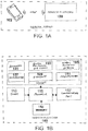
- FIG. 1A shows an exemplary sensing system for sensing motion of a user, in which a sensor platform 100 is configured to wirelessly communicate with a mobile device 102 (e.g., a smart phone) and/or a communications network via a wireless communications link (e.g., using one or more RF protocols such as Bluetooth LE, Bluetooth, Wi-Fi, and/or Zigbee).
- the sensor platform is also configured for wired communication (e.g., via an Ethernet cable, universal serial bus (USB), etc.) with the mobile device 102, personal computer, tablet, and/or the like.
- FIG. 1B is an example block diagram of the sensor platform 100 of FIG. 1A , in which a collection of sensors (barometer 101, Global Positioning System (GPS) subsystem 103 (e.g., including a GPS receiver), global positioning antenna 105, accelerometer 107, gyroscope 109, and magnetometer 111) and a timer 113 are electrically coupled to a processor 115, configured to send/receive signals via a communications port 117.
- GPS Global Positioning System
- any other type of pressure sensor e.g., atmospheric pressure sensor, air pressure sensor, pressure altimeter, and/or the like
- the barometer 101 or other pressure sensor can measure/sense changes in pressure, for example as the user is moving.
- the GPS subsystem 103 can acquire, via the global positioning antenna 105, a GPS signal including a user's geolocation (e.g., including latitude, longitude, altitude, and the current time).
- the accelerometer 107 can be a single-axis, two-axis, or three-axis accelerometer.
- IMU inertial measurement unit
- the accelerometer 107 or other IMU can measure/sense magnitude and direction of "proper acceleration” (physical acceleration), velocity, and/or orientation of a user.
- the gyroscope 109 e.g., a MEMS gyroscope
- the magnetometer 111 can measure the orientation of a user with respect to the Earth's magnetic field.
- each of the accelerometer 107, the gyroscope 109, and the magnetometer 111 is capable of measuring orientation, one or more can be omitted from some designs of the sensor platform.
- a separate gyroscope 109 and/or magnetometer 111 may not be included in the sensor platform.
- True net acceleration in physical space can include both linear acceleration (e.g., as measured by an accelerometer) and angular acceleration (e.g., as measured by a gyroscope).
- the timer 113 can provide time data (e.g., time stamps corresponding to historical measurements taken by sensors of the sensor platform 100).
- Time data can be stored locally (e.g., in a memory 114), used by the processor 115 for computation of one or more metrics of interest described herein, and/or transmitted via the communications port 117 (e.g., along with other measurement data derived directly from the sensors of the sensor platform 100 or stored in memory 114) to a mobile device (e.g., smart phone 102) or other remote processing device, e.g., over a communications network.
- the communications port 117 includes, or is replaced by, a "data interface" which can include an antenna, an Ethernet connection, a USB port, or any other wireless or wired interface to facilitate communication (and transfer of data) between the sensor platform and a remote device (e.g., a mobile device, a communications network, etc.).
- signal processing and feature extraction is completed via one or more algorithms running on one or more processors (e.g., processor 115).
- the signal processing and feature extraction can be performed partially on the sensor platform (e.g., sensor platform 100, which can be an apparel-embedded or athletic accessory-embedded portion of the sensing system) and may also be completed partially on a processing device (e.g., mobile device 102 or other device in wireless communication with the sensor platform).
- the sensor platform 100 transmits raw data (once measured/collected and/or stored in memory 114) to a remote processing device (e.g., mobile device 102or other device in wireless communication with the sensor platform), either autonomously (e.g., according to a delivery schedule) or in response to a request received at the sensor platform from the remote processing device, for example by RF communications over a wireless communications link established by the communications port of the sensor platform, or via a wired connection (e.g., Ethernet) such that the remote processing device performs the signal processing.
- Information can be provided to the user (1) partially by the sensor platform and partially by a mobile device; (2) primarily or exclusively by the sensor platform (e.g., sensor platform 100); or (3) primarily or exclusively by the mobile device (e.g., mobile device 102).
- a user interface and a computation device may reside within the same device, e.g., within mobile device 102, or in the sensor platform 100 itself, or may be housed separately (e.g., a computation device or processor within the sensor platform and a user interface in a mobile device, or vice-versa).
- a server e.g., one or more remote servers, "the cloud,” etc.
- a single server may gather data from one or more sensor platforms 100. Data may be transmitted from the sensor platform 100 to the server via a proxy, such as a computation device.
- FIGS. 2A-2D are renderings of a sensor platform 200, according to some embodiments.
- the sensor platform 200 can be used, for example, as part of a sensing system (e.g., as sensor platform 100 in FIG. 1A ).
- FIG. 2A is a side view of an assembled sensor platform 200, in which an enclosure or "housing" 219 and two metal snaps 223A, 223B are visible.
- FIG. 2B is a side view of a partially disassembled sensor platform 200, in which a battery 221 and two metal snaps 223A, 223B are visible.
- FIG. 2C is a top view of an assembled sensor platform 200, showing enclosure 219.
- FIG. 1A is a side view of an assembled sensor platform 200, in which an enclosure or "housing" 219 and two metal snaps 223A, 223B are visible.
- FIG. 2B is a side view of a partially disassembled sensor platform 200, in which a battery 221 and two metal snaps 223A
- 2D is a top view of a partially disassembled sensor platform 200, in which a portion of the enclosure 219, a printed circuit board 225, a vent 227, an accelerometer 207, a gyroscope 209, a barometer 201, a microcontroller (or “processor”) 215 operably coupled to a memory 216, and an antenna 205 are visible.
- the metal snaps 223A, 223B can be used to mechanically and/or electrically couple the sensor platform 200 to a garment (e.g., a shirt, shorts, arm band, leg band, shoe, etc.) or an accessory (e.g., a chest strap, arm band, leg band, watch, wrist band. bracelet, and/or the like) so that the sensor platform 200 is in close proximity with, or in contact with, the user's body.
- the processor 215 is configured to: (1) translate multi-axis motion data, using orientation data (e.g., measured by the accelerometer 207 and/or the gyroscope 209), from the reference frame fixed with respect to the housing 219 to a reference frame fixed with respect to the Earth so as to yield translated multi-axis motion data; (2) decompose the translated multi-axis motion data into horizontal motion components and vertical motion components in the reference frame fixed with respect to the Earth; and (3) estimate power expended by the user based on the horizontal motion components and the vertical motion components.
- orientation data e.g., measured by the accelerometer 207 and/or the gyroscope 209
- the memory 216 can store previously measured multi-axis motion data, and the processor 215 can be configured to vary the first sampling rate based on a comparison of the motion data to the previously measured multi-axis motion data.
- the sensor platform 200 or sensing system can include a pressure sensor (e.g., an atmospheric pressure sensor or air pressure sensor, such as barometer, operably coupled to a processor.
- a pressure sensor e.g., an atmospheric pressure sensor or air pressure sensor, such as barometer
- barometer 201 is operably coupled to the processor 215 via PCB 225, to measure changes in pressure experienced by the system due to variations in altitude and/or wind resistance.
- the sensor platform or sensing system can include a Global Positioning System (GPS) receiver (e.g., of GPS subsystem 103 in FIG. 1A ), operably coupled to the processor 215, to receive a GPS location signal representing a location of the system.
- GPS Global Positioning System
- the sensor platform 200 can also include a flexible potting compound (see, e.g., discussion of FIG. 4 below), disposed within the housing 219, to reduce mechanical stress experienced by at least one of the housing 219, the IMU (e.g., accelerometer 207), and the orientation sensor (e.g., gyroscope 209), and/or other components of the sensor platform 200 whose performance can be affected by excessive mechanical stress, e.g., due to impact forces during running, vibration, etc.
- a flexible potting compound see, e.g., discussion of FIG. 4 below
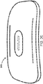
- FIGS. 3A and 3B are renderings of top and bottom views, respectively, of an assembled sensing platform 300 according to some embodiments
- FIG. 3C is a rendering of a top perspective view thereof.
- the sensor platform 300 can be used, for example, as part of a sensing system (e.g., as sensor platform 100 in FIG. 1A ).
- the sensing platform enclosure or housing can include a replaceable cover coupled (e.g., threadably) to the housing, that a user can rotate for removal, e.g., to allow the user access to the internal power source (e.g., a coin cell battery) for replacement.
- the profile of the sensing platform housing as shown in FIGS.
- 3A-3C can have a smooth, contoured profile and compact form factor to facilitate integration into a wearable electronics garment and/or for attachment to a garment or accessory.
- Two holes shown in FIG. 3A ) can be provided for mechanical and/or electrical attachment to the garment or accessory (e.g., via snap engagement).
- FIG. 4 shows a sensor platform 400 with an enclosure (also referred to herein as a "housing” or “package”) for harsh environments, according to some examples.
- the sensor platform 400 can be used, for example, as part of a sensing system (e.g., as sensor platform 100 in FIG. 1A ).
- the enclosure of the sensor platform 400 may be embedded in a piece of apparel (e.g., in an athletic shoe, a shirt, shorts, etc.) or an athletic accessory (e.g., a chest strap, arm band, leg band, wrist band, headband, watch, smartphone, dongle, and/or the like) that is, or will be during use, subject to high forces, and as such may include one or more features (such as those shown in FIG. 4 ) to promote durability and/or to protect the embedded electronics of the sensor platform 400.
- a piece of apparel e.g., in an athletic shoe, a shirt, shorts, etc.
- an athletic accessory e.g., a chest strap, arm band
- the sensor platform enclosure can be a high-performance, robust enclosure for protecting embedded electronics.
- the sensor platform 400 enclosure as shown in FIG. 4 includes an arched top 431, a reinforced bottom plate 432, a plurality of weight distribution pillars 433 to distribute forces (e.g., impact, vibration, etc.) experienced by the sensor platform, a flexible potting compound 434, a plurality of shock absorbers 435 each disposed at an end of a corresponding weigh distribution pillar, a printed circuit board (PCB) 436, and a battery 437 (e.g., a coin cell battery).
- PCB printed circuit board
- a package/enclosure e.g., including arched top 431 and/or bottom plate 432 with structural rigidity can be used.
- the enclosure e.g., including arched top 431 and/or bottom plate 432 can include flexible sections placed in areas mirroring the points of flex, e.g., joints of the human foot.
- the bottom side of the shoe can experience forces that are both high in pressure and confined to small spatial areas. Some examples include stepping into a curb corner, an upturned rock, upturned metal bolt, or any other often accidentally-encountered debris. Such forces pose a risk to embedded circuitry through either extreme torsion (e.g., possibly damaging solder joints), or other types of damage, such as punctures.
- the enclosure e.g., including arched top 431 and/or bottom plate 432
- a shoe with embedded circuitry can include protection against accumulated water, dirt, and sweat encountered over the life of the shoe.
- the enclosure e.g., including arched top 431 and/or bottom plate 432
- the enclosure can include a watertight or water-resistant material.
- a shoe with wirelessly connected embedded circuitry can include an enclosure that will not impair the RF performance of its wireless antenna.
- metallic and other conductive materials may not be used on the upper portions of the enclosure (e.g., arched top 431) which may otherwise impair wireless antenna signal strength.
- the density of the enclosure (e.g., including arched top 431 and/or bottom plate 432), in some embodiments, is designed so as not to exceed the density of the surrounding shoe materials, thereby adding little or no extra weight as compared with a shoe without embedded circuitry.
- the enclosure size is kept small while increasing or maximizing structural support to provide high performing load-bearing and shock-absorption capabilities.
- the sensing device enclosure can also include one or more of the following:
- the package/enclosure (e.g., including arched top 431 and/or bottom plate 432) can include both rigid and flexible materials, each of which may be both light in weight ("lightweight”) and have high strength (“rugged").
- Rigid materials can include lightweight yet high-strength Kevlar® plastics or woven carbon fibers.
- Flexible materials can include flexible potting compounds, foams, and fabrics.
- Vertical enclosure walls of the package/enclosure can be reinforced.
- the enclosure walls can be made thicker by additional impregnation of high strength materials throughout in designs advantageous for increased load-bearing performance (e.g., in a weight-saving honeycomb structure).
- the top (foot-facing) side of the enclosure can have a curved arch shape (e.g., also placed with and following the contours of the human arch) to distribute the weight of the user directly and evenly into each reinforced load-bearing structure of the enclosure.
- Honeycombed bridge-like supports connect the arch top with the reinforced walls for extra weight-bearing and shock-absorbing capability.
- Sensor platform 400 of FIG. 4 for example, includes a top arch/exterior wall 431.
- the package/enclosure may employ a reinforced flat plate (e.g., reinforced bottom plate 432 in FIG. 4 ) for added toughness/durability on the road-facing side of the shoe.
- the reinforced plate can include materials such as metal plate or other high-strength materials, e.g., made from synthetic fibers such as Kevlar® plastics and woven carbon fiber.
- the reinforced plate can be sized to match the areas of circuitry it is intended to protect, and can be cut into sections that link together so as not to compromise the overall flexibility performance of the shoe. It can be attached to the main package itself through an epoxy resin bonding process, e.g., prior to or during the shoe manufacturing process.
- Multiple cylindrical pillars e.g., load-bearing weight distribution pillars 433 of FIG. 4
- the pillars can thus be configured to transfer applied stresses from the top of the arch or, alternatively, from the reinforced bottom plate, to completely bypass the embedded circuitry.
- the bottoms of the pillars can be positioned so that they rest against resin or rubber shock absorbers (e.g., shock absorbers 435 of FIG. 4 ) disposed between the pillars and the coin battery.
- the package/enclosure of the sensor platform 400 can include flexible sections to allow movement of the enclosure with the natural movement of the shoe under scenarios, such as normal walking, running, and/or sports playing.
- Such flexible sections can be made of flexible materials such as rubbers and resins, and can be attached in the area between the enclosure bottom and the reinforced bottom plate 432.
- a flexible, non-conductive epoxy resin canl be used to partially or entirely fill the package/enclosure (e.g., as defined between the arched top 431 and the bottom plate 432) containing both circuitry and battery.
- the flexibility of the resin can aid in shock absorption to buffer and neutralize mechanical stresses applied to the enclosure.
- the potting compound can also provide watertight protection from water, dirt, and sweat, while also protecting the circuitry from unnecessary access and/or tampering by the user.
- the sensor platform 400 of FIG. 4 for example, includes a flexible potting compound 434.
- a system for measuring motion of a user during physical activity can include a housing and an inertial measurement unit (IMU) disposed within the housing to acquire multi-axis motion data at a first sampling rate.
- the multi-axis motion represents motion of the system in a reference frame fixed with respect to the housing.
- An orientation sensor e.g., an accelerometer, gyroscope, or magnetometer
- the IMU itself (e.g., when the IMU is an accelerometer) serves as an orientation sensor by sensing the direction of weight changes of the user.
- the orientation data represents an orientation of the system, for example with respect to the Earth.
- a processor is disposed within the housing and operably coupled to the IMU and to the orientation sensor, to vary the second sampling rate based on the multi-axis motion data.
- a memory disposed within the housing and operably coupled to the processor, is configured to store the multi-axis motion data and the orientation data.
- a data interface operably coupled to the processor, is configured to transmit the multi-axis motion data and the orientation data to another computing device.
- the housing can include an arched wall (e.g., arched top wall 431), a reinforced plate (e.g., reinforced bottom plate 432) disposed opposite the arched wall, and a plurality of weight distribution pillars (e.g., weight distribution pillars 433) between the arched wall and the reinforced plate.
- arched wall e.g., arched top wall 431
- reinforced plate e.g., reinforced bottom plate 432
- weight distribution pillars e.g., weight distribution pillars 433
- the orientation sensor comprises a gyroscope.
- the memory can store previously measured multi-axis motion data, and the processor can be configured to vary the second sampling rate based on a comparison of the multi-axis motion data to the previously measured multi-axis motion data.
- the processor can also be configured to (i) estimate when the user is airborne based on the multi-axis motion data and (ii) disable the gyroscope when the user is airborne.
- a user affixes a sensor platform as described herein (e.g., sensor platform 100 of FIG. 1A ) to a surface of, or in close proximity to, his body (e.g., secured by a chest strap, wrist strap, leg band, etc.) and conducts a physical activity such as walking, running, dancing, and/or the like.
- the sensor platform e.g., including one or more inertial measurement units, an orientation sensor, and an optional barometer
- the body may be placed on various locations of the body, for example, at the following locations, as shown in FIG.
- each location can have one or more of the following advantages: (a) convenience to the user, (b) accuracy of measuring running and/or walking technique and distance, (c) accuracy in measuring the geographic position of the user, (d) improved sensed data quality, (e) improved user comfort, (f) monitoring of one or more limbs of a user; and (f) reduced stress on the sensing device.
- beneficial locations can include within or on a strap attached to the ankle, leg, wrist, waist, or torso.
- the sensor platform can also be placed within or on apparel such as clothing, belts, or shoes. It can also be placed on, under, or to the side of the foot.
- sensing devices can be used per person or group. For example, in some situations, it may be difficult or impractical to monitor more than one limb, and the estimation accuracy enabled by such data may differ depending on limb. In such cases, the sensing device(s) can be placed on the limb enabling more accurate estimation(s) of metrics of interest.
- the sensor platform can include a user interface (e.g., including an electronic display, touchscreen, pushbuttons, dials, indicator light(s), speaker(s), microphone(s), keyboard, etc.), for example to allow users access to information about metrics and maps described herein.
- the user interface functionality is divided between/among the sensor platform, and software running on a mobile device (e.g., commodity or special-purpose devices, such as smartphones) that communicates with the sensor platform.
- the user interface functionality resides within a mobile device.
- the user interface functionality resides within the sensor platform.
- the device that contains the user interface e.g., the mobile device 102 and/or the sensor platform 100 of FIG. 1A
- the sensor platform can provide feedback to a user in audio-visual form during use.
- the sensor platform and user interface can provide off-line and real-time information to the users.
- the real-time information can be easy to access, and accessible during physical or mental activity.
- a compact colored light on the sensor platform, or audio output from the user interface may be used to indicate information to a user.
- the off-line information is organized to allow users to vary the level of detail and type of information displayed. For example, users may scroll through a map or timeline of activities to see detailed information about metrics of interest for different times and locations.
- the system may also be prompted to provide information of interest that did not originate in the sensor platform, e.g., metrics of interest from other users, the time, and personal information stored on the interface device (e.g., a smartphone).
- the sensor platform and/or interface device can provide active and/or passive feedback to the users.
- Active feedback has the potential to distract the user from physical or mental activities, and can be presented on a schedule chosen by the user, when explicitly requested, or when determined to be valuable due to values or patterns in metrics of interest.
- Users may explicitly request active feedback through actions that require little deviation from their ongoing activities, e.g., by a gesture such as tapping a foot, changing the angle of a limb, or tensing a particular muscle.
- Feedback about metrics of interest may be provided via subtle changes in the rhythm, harmony, and dissonance of automatically generated music, or through automatic changes in music recordings or media references provided by the user.
- the feedback can be adjusted and synchronized to motion patterns of the user. For example, subtle notes can be played to direct the user toward the ideal cadence.
- subtle notes can be played to direct the user toward the ideal cadence.
- an activity such as running starts
- another bass or drumbeat sound can be joined/added.
- the background beat can naturally adjust phase to match that of the athlete's steps, and/or adjust period to be slightly closer to the ideal than the user's current cadence. As the user adjusts cadence slightly in the right direction, the background beat can take another step towards the optimal. When the user hits the optimal cadence, both beats can overlap.
- the notes for the beats can be harmonic.
- the athlete footstep beat can be composed of two notes. They can be harmonic when other efficiency metrics are well optimized. Otherwise, they can be dissonant. Different tones, degrees of harmony, and tone durations can be used to provide information about multiple metrics of interest.
- a variant of this interface technique is to modify parameters of music provided by the athlete. For example, a piece of music with appropriate initial tempo can be automatically chosen from multiple pieces of music provided by the user. Information about metrics of interest can be provided by signal processing the music during playback, e.g., changing the playback speed, frequency-shifting the music, and emphasizing or deemphasizing particular instruments and voices using signal processing techniques. The timing of active feedback may also be controlled to produce sound at ideal times, e.g., between pieces of music or during quiet intervals.
- the sensing device detects user gestures and the contraction of particular muscles and, in concert with computation device(s), uses specific actions to enable control of other objects. For example, a user may dance and have the types and intensities of dance steps modify the tempo, instruments, volume, and tones of music, or temporal and color patterns of lighting effects. Examples of actions that may be controlled include sending emails, sending short messages, and controlling building temperature.
- Multiple sensing and/or interface devices may be used by different uses to enable collaboration, education, and entertainment.
- Metrics are numerical values, or vectors of numerical values that are computed based on measurements and/or based on information explicitly provided by individuals.
- Metrics of interest gathered from one or multiple users can be transmitted to an aggregating computing device for real-time aggregation and display.
- metrics of interest for users participating in training or competitive sports can be aggregated and displayed, perhaps to large audiences concurrently with live video of the associated athletic activity, for educational or entertainment purposes.
- These data can also be used off-line, to assist users in emulating other, more advanced, users.
- a user might emulate the metrics of interest for a group of top athletes in their athletic activity or sport of interest.
- These data may also be used to assist in judgments in athletic competitions.
- a sensing and interface device may communicate the time at which a race is started and ended or determine whether sensed data indicate a prohibited action during a sporting event.
- Metrics of interest gathered from multiple users by separate sensing devices can be aggregated on computation devices and used to make leaders and participants in the physical activity aware of positions, activities, and physical and emotional states of other participants. For example, individuals involved in group athletic events can use this information to better coordinate their actions toward a shared goal. Another use case is allowing users to compete or collaborate with other users, who might be at physically separate locations. Specific actions may also be used to initiate communication. Action/location/time context may also be used to trigger the interface device to provide information that may be helpful to the user, including information about relevant goods and services.
- data is gathered by the sensor platform and analyzed on the sensor platform, and/or on a remote computing system such as a smartphone, smartwatch, sports watch, and/or on a network-attached server or virtual server.
- a remote computing system such as a smartphone, smartwatch, sports watch, and/or on a network-attached server or virtual server.
- manual and/or automated coaching e.g., based on power determinations
- a user e.g., a runner or walker.
- Real-time sensing and analysis enables real-time calculation of metrics of interest. These metrics (e.g., the power metric, described in greater detail below) can be selectively provided to users to assist them in reducing or minimizing injury risk, improving athletic performance, and/or improving the benefits of training sessions.
- Such information can also be used to advise the user on appropriate adjustments in technique to bring about desired results such as improved running and/or walking efficiency, reduced injury risk, improved muscle adaptation results, and/or improved pace. For example, users can be warned when their fatigue levels have reached levels rendering them susceptible to injury. Users who would have better training results by training more or less intensely can be guided to do so by the sensing and interface devices. Users with metrics indicating suboptimal technique can be guided to adjust their technique. For example, runners with excessive braking force can be coached to change their technique, thereby improving athletic performance.
- a sensing platform 600 can gather and analyze data.
- the sensing platform 600 may also transmit the data to a remote computing system, such as a smartphone 602, smartwatch 604, sports watch 606, and/or on a network-attached server or virtual server, for analysis.
- the sensor platform 600 can be used, for example, as part of a sensing system (e.g., as sensor platform 100 in FIG. 1A ).
- the analysis results including the user's ability to sustain particular power levels for particular durations, can be used to advise the user on appropriate training intensities and durations to bring about the adaptation necessary to reach the user's power and performance goals.
- Automated coaching can also be used, for example, to warn users of impending overtraining risk and/or to provide advice on pacing.
- Coaching advice may be provided through vibration and/or sound produced by the sensing platform.
- Coaching advice may also be provided via vibration, screen display, or audio output from a smartphone 602, smartwatch 604, and/or sports watch 606, e.g., worn or carried by the user.
- communication between the sensor platform and other components of the sensing system is carried out through one or more wireless communication technologies such as Bluetooth LE, Bluetooth, Wi-Fi, and Zigbee.
- coaching advice can be provided using comparison's of user running and/or walking techniques with those of expert runners and walkers, and with theoretical ideal techniques based on physiological models of user body structures informed by height, weight, limb, and/or limb segment measurements explicitly provided by the user or inferred based on user motion patterns.
- the method of displaying user techniques relative to expert or ideal techniques can include display of superimposed comparative animations and/or real-time and offline feedback on specific aspects of technique the user is capable of adjusting, including any of the metrics described herein.
- Some components of the sensor platform and/or the sensing system can be shut down periodically to conserve power.
- one or more hardware components in the sensing system has its activity state managed in order to achieve the current desired tradeoff between electrical power consumption and measurement accuracy or measurement latency.
- the sensors with the highest power consumptions are activated least frequently.
- Signal processing and prediction techniques can be run by the processor (e.g., residing within the sensor platform and/or within a mobile device in wireless communication with the sensor platform) on data from more power efficient sensors to determine when changes in motion patterns occur that would require activation of more power demanding sensors.
- the occurrence of previously encountered patterns in accelerometer data are used to enable estimation of angle changes normally determined using gyroscope and magnetometer data by reusing remembered values instead of re-activating these orientation sensors.
- the power management states of other portions of the sensing system e.g., the smartphone 602, smartwatch 604, or sports watch 606 of FIG. 6 ) are also controlled based on the current accuracy and latency requirements of the sensing system.
- the mechanical power output of the human body is a function of the velocity and the forces of and on the various parts of the body.
- an inertial measurement unit e.g., an accelerometer, such as a three-axis accelerometer
- a gyroscope and/or magnetometer e.g., a Bosch Sensortec BMA150 accelerometer
- a pressure sensor e.g., a Bosch Sensortec BMA150 pressure sensor
- Computation and sensing can be carried out entirely on a microcontroller in the sensor platform, or some or all computation and/or sensing can be offloaded to a remote device such as a smartphone.
- the entire sensing system including the sensor platform and communicating external hardware and software, is herein referred to as the "sensing system.”
- the disclosed sensing system includes one or more of the following capabilities: (1) determine the motion, positions, and orientations of one or more parts of the body of a user wearing the sensor platform, (2) use gathered/sensed data to carry out detailed, and in some embodiments comparative, time-dependent gait analysis of one or more limbs, (3) determine the incline of the user's path, (4) determine the impact of wind on human speed and forces, (5) measure the passage of time, (6) use general physical properties of bipedal motion and a combination of the data described in the above items to determine instantaneous body velocity, force, and the passage of time (thereby allowing power expenditure to be calculated), and (7) control the activities of sensing system components such as sensors (e.g., one or more inertial measurement units, accelerometers, gyroscopes, temperature sensors, inertial sensors, force sensors, pressure sensors, Global Positioning System (GPS) receivers, flex sensors, etc.), processors, wireless communication transceivers, and/or display elements,
- sensors e
- IMU inertial measurement unit
- Acceleration samples can be gathered by the IMU (e.g., an accelerometer) at a variable frequency that is adjusted based on the current accuracy and power consumption requirements. These data represent acceleration as viewed from the reference frame of the sensor. However, they may not represent acceleration as viewed form the reference frame of the Earth.
- the IMU e.g., an accelerometer
- an inertial measurement unit can, in some embodiments, be combined with a magnetometer or gyroscope for orientation estimation. Of these two sensors, magnetometers generally have lower power consumptions.
- Gyroscope and/or magnetometer samples may be gathered at a variable frequency that is adjusted based on the current acceleration and power consumption requirements. These data may be used to determine the changes in orientation of the sensor relative to the direction of gravity or some part of the user's body. This information may be used, for example, to translate the accelerometer data from its reference fram to the reference frame of the Earth. Some environments, such as indoor environments where large pieces of ferrous metal are present, can interfere with magnetometer use for orientation estimation. In scenarios where magnetometer readings are unreliable, e.g., inconsistent with gyroscope readings, a gyroscope may be used instead.
- measurement error can cause absolute gyroscope orientation readings to accumulate error, thereby producing an absolute orientation that may be inconsistent with reality.
- the orientation may be recalibrated with each step.
- gyroscope and/or accelerometer readings are used to determine when the foot is placed flat on the ground.
- the ground angle can be estimated using position and topographical data, or measured using the accelerometer.
- a proportional integral derivative (PID) algorithm may be used to recalibrate the gyroscope to reduce or minimize the error between the angle measured by the gyroscope and that determined through other means.
- the PID algorithm can be disabled and the gyroscope can be used to measure the angle of the foot until it is again in contact with the ground.
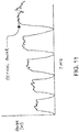
- the presence of the foot on the ground may be detected by determining when all of the following are true: (1) The downward acceleration is approximately 9.8 m/s 2 (note that a different estimation approach may also be used, in which the foot is determined to be on the ground when the length of the vector given by a multi-access accelerometer is approximately 9.8 m/s 2 ); (2) The change in angle over last 50 milliseconds is approximately zero; (3) Foot impact, as detected with an accelerometer, occurred approximately 300 ms prior.
- the 3 axis accelerometer reading can be multiplied (e.g., via a processor on board the sensor platform and/or via a remote processor on a mobile device or other device in wireless communication with the sensor platform) by a rotation matrix in order to determine which direction the person is facing.
- acc x ′ acc y ′ acc z ′ cos ⁇ ⁇ 0 sin ⁇ ⁇ 0 1 0 ⁇ sin ⁇ ⁇ 0 cos ⁇ ⁇ ⁇ acc x acc y acc z
- acc x , acc y , and acc z are readings from the three-axis accelerometer
- acc' x . acc' y , and accz are the orientation-compensated readings from the three-axis accelerometer
- ⁇ is the angle measured by the gyroscope. This approach may also be used with the gyroscope being replaced by a magnetometer.
- a pressure sensor e.g., an atmospheric pressure sensor, air pressure sensor, barometer, pressure altimeter, and/or the like
- a pressure sensor can be included in the sensor platform used to detect changes in a user's elevation (i.e., attitude or vertical position).
- Filtering e.g., low-pass filtering with a cutoff frequency of ⁇ 0.2 Hz, or band-pass filtering with a range of ⁇ 0.1Hz - ⁇ 0.3Hz
- Filtering can also be used to compensate for air that is incident on the runner (e.g., strong winds, puffs of air, abrupt changes in wind patterns, and/or other aerodynamic factors that cause rapid pressure changes, any of which may vary with time, location, running form, body/limb positioning of the user, and/or other factors) so that the signal is more stable and/or relates primarily to the user's altitude.
- the cutoff frequency can be changed dynamically to account for changes in a runner's attitude.
- the forward motion of a person can be estimated accurately without the use of GPS, and are designed to mitigate or avoid high power consumption and short battery lifespans for the sensing platform.
- a sampling technique is used to avoid frequent activation of a high power consumption gyroscope.
- a sampling technique in which the gyroscope is deactivated for a subset of paces can result in accumulation of motion and position error for those paces.
- an adaptive sampling technique can be used, in which the gyroscope is reactively activated when there is a significant difference between the time-varying multi-axis accelerometer data for that pace and a library of accelerometer data from (not necessarily all) prior paces.
- the gyroscope-enhanced motion estimates from that pace can be used.
- Accelerometer pace data may be compressed via curve fitting. A subset of paces will have their data stored, with a size limited by available memory and comparison overhead. Heuristics, e.g., based on variation in pace and/or cadence, may be used to make the search for matching prior pace accelerometer data faster.
- low-frequency measurements can be used to classify activity.
- a power efficient accelerometer can be used in a low-frequency, low-power sampling mode to classify activity, e.g., walking or running.
- the sensing system can transition to a higher-frequency, higher-power mode, for example when an activity meriting such a transition is detected, e.g., running.
- high-frequency measurements can be made when appropriate for the current activity. This transition can be automated, thus requiring no command from, or explicit interaction with, the user.
- a Fourier transform can be applied to the raw data gathered at low sampling frequency, either on the sensor node or on an external device, allowing temporal features to be detected with high accuracy.
- Different methods of analysis can also be applied at different sampling frequencies. For example, at low sampling frequency, frequency-domain analysis can be used, and at high sampling frequency, time-domain analysis can be used. This technique facilitates transition among sensing modes with different temporal resolutions and power consumptions without explicit commands or interaction with the user. This achieves a good trade-off between computational/energy cost and feature extraction accuracy.
- contextual information such as measured stride length for a particular set of physiological and motion-related metrics, can be used together with measurement of motion-related metrics.
- Drift compensation Multiple sensors are capable of providing data allowing person and limb position, motion, and orientation to be estimated. Some of these sensors have higher power consumptions than others when activated.
- One relatively low power sensor in the inertial measurement unit is typically an accelerometer.
- inertial measurement units typically do not allow orientation to be estimated. Therefore, an inertial measurement unit can, in some embodiments, be combined with a magnetometer or gyroscope for orientation estimation. Of these two sensors, magnetometers generally have lower power consumptions. If feasible for a given implementation, the magnetometer can be used in combination with the accelerometer. However, some environments such as indoor environments where large pieces of ferrous metal are present, can interfere with magnetometer use for orientation estimation.
- a gyroscope may be used instead.
- the described position, motion, and orientation estimation technology is generally quite accurate, some small amount of error can accumulate over long time intervals. Therefore, if a GPS receiver is available, it may be infrequently activated to correct accumulated position estimation error.
- an inertial measurement unit, magnetometer, gyroscope, and GPS receiver (or subset thereof) can be used together to accurately estimate person and limb position, motion, and orientation with minimal energy consumption.
- an IMU combined with a gyroscope, may be used to determine the orientation of a limb is described first.
- human feet are the body parts for which position and orientation are measured. Data collected by the sensor platform may be used to estimate the coarse-grained location of the person. They may also be used to track the paths and orientations of limbs during athletic activities such as running, or swinging a baseball.
- Orientation-corrected accelerometer readings can be integrated over time (e.g., using a processor disposed within the sensor platform or within a mobile device in wireless communication with the sensor platform) to determine a three-dimensional path of the limbs being monitored by sensing platforms.
- a method of measuring motion of a user during physical activity is performed using a system comprising an inertial measurement unit (IMU) and an orientation sensor disposed within a housing.
- the method includes: (1) acquiring multi-axis motion data with the IMU at a first sampling rate, where the multi-axis motion represents motion of the housing in a reference frame fixed with respect to the housing; (2) acquiring orientation data with the orientation sensor at a second sampling rate, where the orientation data represents an orientation of the housing with respect to the Earth; and (3) varying the second sampling rate based on the multi-axis motion data. Varying the second sampling rate can include comparing the multi-axis motion data to previously measured multi-axis motion data. Alternatively or in addition, varying the second sampling rate includes estimating when the user is airborne based on the multi-axis motion data, and disabling the orientation sensor when the user is airborne.
- An example of a method includes: (1) translating the multi-axis motion data, using the orientation data, from the reference frame fixed with respect to the housing to a reference frame fixed with respect to the Earth so as to yield translated multi-axis motion data; (2) decomposing the translated multi-axis motion data into horizontal motion components and vertical motion components in the reference frame fixed with respect to the Earth; and (3) estimating power expended by the user based on the horizontal motion components and the vertical motion components.
- the method can include varying the first sampling rate based on a comparison of the multi-axis motion data to previously measured multi-axis motion data.
- the method can also include measuring changes in pressure experienced by the system due to variations in altitude and/or wind resistance.
- a sensing platform as described herein can be configured to wirelessly communicate with a mobile device (e.g., a smart phone - see 102 of FIG. 1A ) via a wireless communications link (e.g., Bluetooth LE, Bluetooth, Wi-Fi, and/or Zigbee) established through a communications port (e.g., communications port 117 of FIG. 1B ), for example to transmit sensor data collected during use by a user, to the mobile device for signal processing.
- the sensing platform can be configured for wired connection (e.g., communications port 117 of FIG. 1B ) with a mobile device (e.g., a smart phone) for the transfer of sensor data collected during use by a user (e.g., stored within a memory disposed within the sensor platform).
- a method and system for activating an electronic device via the Internet is disclosed.
- a server system receives purchaser information, e.g., email address, unique identifier of the sensor platform, etc.
- client application e.g., a mobile software application, or "app”
- the server system can transfer the unique identifier of the device to the purchaser's client system, and the sensor platform can automatically be activated and/or connected (e.g., wirelessly) to the purchaser's client system and client application.
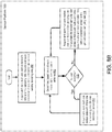
- Automated activation is first enabled (at 701), and a device ID/customer mapping is set (703).
- the mobile application is then installed (705), after which a server sends a device ID to the client system during the first client application invocation (707).
- the processing of raw data/measurements made within the sensor platform can be executed by a processor running on the sensor platform, on a mobile device in communication with the sensor platform (e.g., also functioning as an interface device), and/or on one or more remote servers in communication with the sensor platform and/or the mobile device, to analyze the raw data/measurements (in some embodiments also taking into account contextual information).
- the sensing system uses the results to provide advice to users allowing them to adjust their behavior to improve training, competition, and/or recovery results.
- FIG. 8A An exemplary flowchart, showing the processing of data received from a sensor platform on a processor, is shown in FIG. 8A .
- a processor 815 (which may be compatible with processor 115 of FIG. 1B , and may reside, for example, in a mobile device) establishes, at 840, a communications link with a sensor platform as described herein (e.g., with reference to FIGS. 1A and 1B ).
- the processor 815 sends a request to cause the sensor platform to transmit multi-axis motion data and orientation data via the communications link.
- the processor 815 re-established the communications link at 840.
- the processor 815 then translates the multi-axis motion data from a first reference frame (e.g., a fixed reference with respect to the sensor platform) to a second reference frame (e.g., with respect to Earth) based on the orientation data, thereby yielding translated multi-axis motion data.
- the processor 815 decomposes the translated multi-axis motion data into horizontal and vertical motion components in the second reference frame. Using the horizontal and vertical motion components determined at 846, the processor 815 then estimates, at 848, the power that has been expended by the user for the period of time in which the multi-axis motion data and orientation data were collected by the sensor platform.
- FIG. 8B shows a diagram of the measurement of multi-axis motion and orientation data on a sensor platform, according to some examples.
- a sensor platform 800 (which may be compatible with the sensor platform 100 of FIG. 1A ) acquires, and stores in a memory, multi-axis motion data with an IMU at a first sampling rate, and also acquires, and stores in the memory, (e.g., concurrently) orientation data with an orientation sensor at a second sampling rate.
- the sensor platform determined, at 852, whether the user wearing the sensor platform 800 is airborne (i.e., his/her feet are not contacting the ground), based on the multi-axis data acquired/stored at 850.
- the sensor platform continues, at 854, to acquire and store multi-axis motion data with the IMU at the first sampling rate, but also disables the orientation sensor. If the user is not airborne at 853, then the sensor platform continues, at 856, to acquire and store multi-axis motion data with the IMU at the first sampling rate, and may vary/update the second sampling rate (of the orientation sensor), e.g., based on the stored multi-axis motion data (which, for example, may be indicative of whether the user is walking, running, etc.). Thus, at 856, the sensor platform 800 also continues to acquire and store orientation data with the orientation sensor, but at the updated second sampling rate. As shown in FIG. 8B , steps 852, 853, 854 and 856 may be iteratively performed, as appropriate, e.g., throughout the duration of time that measurements are taken (e.g., over the course of a run or other bipedal motion of the user).
- Information derived from sensors and/or from knowledge of constraints on bipedal motion can be supplied to a predictive model ( FIG. 9 ) (e.g., a physical and data-driven model) to estimate accelerations, velocities, positions, and orientations, e.g., based on observed data and/or available knowledge or a subset thererof.
- a predictive model e.g., a physical and data-driven model
- metrics such as a user's mass and height 902, time 904, position, orientation and motion (906), path inclination 908, and wind velocity 910, are inputs to the predictive model 900, and a user real-time power output 912 is calculated and output.
- learned bipedal motion properties for a particular individual are used to increase the accuracy of acceleration, velocity, position, and orientation estimates. These properties may depend on running and/or walking conditions such as incline, fatigue, and pace. Knowledge of running and/or walking conditions can be used to further increase the accuracy of acceleration, velocity, position, and orientation estimates.
- the following metrics of interest are calculated based on data gathered from the sensor platform. Their calculation can employ a variety of estimation techniques.
- the sensor platform may be equipped with one or more location-specific sensors, such as force sensors, flex sensors, and/or temperature sensors, allowing for derivation of a time-varying map of metrics of interest.
- the device may support measurement of the distribution of impact force across different structures of the feet and legs.
- Fine-grained limb motion patterns can be used to estimate stride lengths.
- Timer(s) within the sensing and/or computation devices can be used to determine stride times. These metrics, combined, can be used to calculate the average speed and/or distance traveled of users.
- FIG. 10 shows exemplary approximate foot acceleration, speed, and distance for one stride during bipedal motion.
- curve 1001 shows how the foot accelerates with time along the vector pointing in the same direction as the foot
- curve 1002 shows how the speed of the foot changes with time along the vector pointing in the same direction as the foot
- curve 1003 shows how the distance of the foot changes with time along the vector pointing in the same direction as the foot.
- the distance can be described as follows: where a , b , and c can be derived by using linear regression to fit a Gaussian distribution to a series of sensor samples or via infrequent calibration to GPS data.
- a , b , and c can be derived by using linear regression to fit a Gaussian distribution to a series of sensor samples or via infrequent calibration to GPS data.
- the accuracy of the speed and distance estimation technique described in the above paragraph can be further improved by infrequent calibration using GPS technology.
- distance estimation error that may accumulate over long estimation periods can be corrected via very infrequent GPS measurements, thus allowing accuracy typical of GPS with energy consumption typical of acceleration sensors.
- These infrequent GPS readings can also be used to calculate new calibration parameters for the equations described in the previous paragraph, further improving accuracy even in the absence of future GPS measurements.
- Accelerometers, gyroscopes, and compasses can be used to estimate changes in direction of motion.
- Contextual information such as knowledge of motion patterns possible for a particular activity or paths possible from a particular location, can be used to constrain direction estimates, thereby correcting for sensing noise.
- Techniques described herein that enable tracking the motion and orientations of body parts over time, may also be used to estimate the coarse-grained location and/or velocity of a person. They may also be used to track the paths and orientations of limbs during athletic activities such as running, or swinging a baseball. Orientation-corrected accelerometer readings can be integrated over time to determine a three-dimensional path of the limbs being monitored by sensing platforms.
- variation in pressure across multiple barometric pressure sensors and time is used to estimate speed and changes in speed.
- the instantaneous derivative of altitude can be approximated by combining timed barometric pressure samples and pace data to allow fitting of a linear incline function, for example to determine instantaneous incline, thereby making long-term variation in barometric pressure due to changes in weather irrelevant.
- incline can be estimated using the position and direction estimation techniques described herein and a map stored on the sensing system translating from position and direction to incline. Incline can also be determined by pressure measurements (using a pressure sensor, such as a barometer, pressure altimeter, and/or the like).
- a pressure sensor can be used to detect changes in a user's elevation (i.e., attitude or vertical position).
- Low-pass filtering e.g., with a cutoff frequency of ⁇ 0.2 Hz
- the cutoff frequency can be changed dynamically to account for changes in a runner's attitude.
- One or more of the following data elements can be used to estimate the forces acting on particular body parts, including the center of mass: acceleration data in body or Earth frame of reference, incline, user weight or mass, and user height. Mass and height may be used to estimate the distribution of body mass across different parts of the body.
- Force can be calculated using knowledge of change in kinetic energy over time, m ⁇ a, where m is mass and a is the acceleration.
- force acting on a runner's center of mass is estimated using the acceleration at the sensing platform location.
- a scaling factor can be used to scale the acceleration seen at a sensor location, such as the hip or trunk, to the acceleration of the center of mass across a wide range of running speeds and cadences.
- a general scaling factor may be used for all users, or a user-specific scaling factor may be used if more information about the user's body structure is known. These approaches can be used to estimate both vertical and horizontal forces.
- a potential energy recovery efficiency scaling factor can be used to determine the impact of uphill or down-hill running on body output power.
- the velocity of the body part of interest is again integrated to determine the position and the following expression is used to estimate the power required for vertical motion: k ⁇ m ⁇ g ⁇ ⁇ ⁇ h ⁇ ⁇ t , where k is a scaling factor, m is the mass, g is the acceleration due to gravity, ⁇ h is the change in sensor height, and ⁇ t is the change in time.
- Wind may affect human velocity and required force exertion, and hence the mechanical power output.
- the sensing platform may determine the wind effect and the corresponding impact on power using one or more of the following methods:
- Temporal changes and patterns in the acceleration experienced by the sensing device can be used to determine the time of impact, after which samples in a short time window can be used to estimate impact forces along multiple physical axes.
- Full frequency spectrum motion metrics can be analyzed to determine when a user's limb is in contact with the ground, allowing calculation of ground time and air time. These metrics can be used to guide users toward improvement in athletic form.
- the sensing system automatically characterizes the physical condition of its user, with or without active changes by the user. Simply wearing the sensing platform during training and/or competition allows data to be gathered on the durations that particular power outputs are sustained by the user's body. These data can concurrently and/or subsequently be used to automatically determine the power outputs at which transitions between different operating zones, such as aerobic and anerobic, occur. Users can also be provided with a plan that indicates target power levels during training, allowing more rapid characterization.
- the force and position change information determined as described herein, combined with measurements of elapsed time, can be used to estimate the power expended to move a part of the user's body.
- the power exerted to move the body center of mass is determined.
- power applied to individual body parts can be estimated. For example, using power applied to legs for step-by-step acceleration and deceleration in addition to center-of-mass power permits a more accurate estimate of whole-body power expenditure.
- An average human, or specific user, power generation efficiency function may be used to translate whole-body power expenditure into metabolic energy expenditure.
- a user's ability to sustain specific power outputs for specific durations may also be used to estimate the composition of activity-relevant muscle groups.
- the percentage of fast-twitch and slow-twitch muscle fibers in the muscles used to generate most power during running can be estimated by measuring the position and slope of a plot of duration as a function of power output when running.
- One embodiment of the present disclosure determines the power being exerted by a human body's muscles on itself using dynamically changing data gathered using a compact body-mounted wireless sensing platform containing one or more of the following sensor types: three-axis accelerometers, gyroscopes, magnetometers, Global Positioning System (GPS) receivers, and atmospheric or air pressure sensors. This power measurement may be used to assist athletic training.
- a compact body-mounted wireless sensing platform containing one or more of the following sensor types: three-axis accelerometers, gyroscopes, magnetometers, Global Positioning System (GPS) receivers, and atmospheric or air pressure sensors. This power measurement may be used to assist athletic training.
- GPS Global Positioning System
- the sensing system can incorporate implementations of signal processing techniques that take into account known physical properties of human running and/or walking behavior to determine forces and/or velocities. Combined with an in-system timer, the force and velocity information permit the calculation of body power consumption (e.g., a "power number").
- the power number can also be derived, at elast in part, from acceleration measurements (e.g., collected by the IMU of the sensor platform).
- This power number can be used, e.g., in combination with pace and/or duration, to guide the user toward more appropriate training, pace, and running and/or walking technique.
- power can be used to enable users to understand the relationship between body power output during running and/or walking and the durations particular power outputs can be maintained. This relationship can be used to quantify the strengths and weaknesses of users, and suggest changes in training plans.
- Body power output can also be used during runs to recommend appropriate instantaneous paces to users in order to increase or maximize entire-run pace in the presence of varying fatigue and running and/or walking environment. Power is also used to determine which changes in running and/or walking form or technique improve or degrade running and/or walking efficiency.
- Running and/or walking efficiency at a particular speed is inversely related to running and/or walking power.
- Metrics of interest associated with energy use that is not useful or less efficient are used to estimate efficiency, i.e., energy productively used divided by total energy used.
- efficiency i.e., energy productively used divided by total energy used.
- cadence, fine-grained three-dimensional limb motion patterns, and impact forces may be used to estimate running efficiency.
- Some metric estimation techniques may result in an accumulation of errors over time. This can, for example, be a result of time-integration of sensor readings such as accelerometer readings.
- temporal and environmental cues can be used. For example, certain repetitive activities such as walking can periodically expose the sensing device to a known velocity, e.g., zero velocity relative to ground when the foot is in contact with the ground. By detecting actions that imply particular metric values, the drifted estimates are calibrated to the actual action-implied values.
- the same concept is applied to location tracking when there are occasionally available accurate location estimates, such as GPS or wireless environment readings.
- Environmental invariants such as impossibility of traveling through walls, can also be used to calibrate location and direction estimates.
- the user power output capabilities described herein can be used to determine the optimal pacing schedule during a run to reduce or minimize the time to complete the run.
- the power output to pace relationship is largely dependent on running and/or walking path incline.
- the path Given knowledge of a planned running and/or walking path, the path can be divided into segments. Each segment can have/be assigned an incline- and/or wind-dependent equation relating power to pace. Duration for the segment can therefore be determined as a function of power. Reducing or minimizing the total duration of the run by dynamically adjusting power output can be achieved by setting segment power output values under constraints on the maximum duration sustainable for each power output level.
- a goal of reducing or minimizing run duration can be formulated as a constrained convex optimization problem and solved, with gradient descent or conjugate gradient search preferably being used.
- future incline angle can be estimated based on average incline angle for the portion of the run already completed. If it is specified by the user that the running and/or walking path is a cycle, then the average incline angle for the portion of the run already completed can be negated to estimate the remaining incline angle. In some examples, the pacing technique is otherwise identical to that described elsewhere herein.
- Metrics calculated from foot and body motion and orientation paths can also be used to characterize user running and/or walking techniques.
- metrics include, by way of nonlimiting example, air time, ground time, cadence, stride length, foot-to-ground angle at impact, fibula-to-ground angle at impact, rate of loading upon impact, and maximum vertical body displacement during stride. For each metric, the difference between left and right stride is determined, which is used to assess asymmetry.
- the sensing device and metric estimation techniques described herein can be used to determine time-, location-, and user-dependent activities. For example, periodic fine-grained limb motion paths can be used to determine whether a user is walking, running, playing basketball, or dancing. Specific moves within activities can also be detected. For example, dance steps such as toe, ball heel, toe stand, the basic movement for any particular dance, chasse, heel turn, or any other particular steps associated with dance can be detected. Similarly, moves in martial arts or yoga forms can be detected. Signal processing and machine learning techniques can be used, for example, to detect actions of interest in any physical activity in which motion or muscle contraction patterns are repeated. The technique may be calibrated to person-by-person variations in moves.
- the running and/or walking techniques of users are characterized by measuring their 3-D foot and/or body motion and rotation paths. These paths are used to compare a user's technique with those of expert athletes and/or theoretically ideal paths. These paths, including the sagittal foot path, can be used to illustrate to users how their techniques differ from preferred techniques.
- the emotional states of users influence many of the metrics computed based on measurements made by the sensing device. Values, temporal patterns, and spatial patterns in these metrics can be used to estimate the emotional and physical states of users in order to provide advice or encouragement, or to change the manner in which information is provided to be better suited to the user's current emotional and physical states. For example, tired individuals may have peculiar fine-grained motion patterns, allowing automatic adjustment in exercise recommendations. Similar changes in motion patterns may be used to detect depression.
- the user may be distracted and have a poor experience.
- the distributions of multiple motion-related and physiological metrics such as impact intensity, ground time, air time, step rate, vertical motion, impact position, the positions of limbs and body, heart rate, skin resistance, and muscle contraction intensity can be calculated to characterize the user's current state.
- These distributions can be used to inform the advice provided to the user. For example, if a user is having a difficult training day, on which step rate has a high variance and is very frequently outside the optimal range, the user can be advised to modify his behavior only occasionally to prevent/reduce annoyance and cognitive overload.
- Knowledge of metric distributions such as that of step rate can be used to ensure that users are prompted to modify their behavior when their metrics deviate by the largest amount from the ideal range.
- the thresholds used to provide prompting to the user can be dynamically adjusted based on the user's capabilities at the time, as measured though the distributions of multiple motion-related and physiological metrics.
- the direction and position estimation techniques described herein can be used to provide position and route data to support automatic derivation of maps of passable interior and exterior routes as well as regions in which people congregate. These maps can be automatically labeled with relevant information about the implications for bipedal motion, e.g., the energy use for regions of a particular hiking trail can be incorporated in the map, as can the influence on ground material in particular indoor and outdoor locations. Locations may also be labeled based on the activities and emotional states of people who have previously occupied the locations.
- Metrics of interest can be used to detect asymmetries in motion, e.g., differences in the intensities, speeds, or motion patterns of right and left limbs. This information can be used to detect evidence of unbalanced development or injuries, and this evidence can be used to automatically or manually make recommendations of changes to technique, training methods, and training intensities. Inefficiencies resulting from asymmetries in antagonistic muscles and nerves can be identified in this manner.
- the sensing system may gather physiological and motion-related data, and computationally convert these data to metrics.
- the sensing system may include one or more modules. Changes (e.g., dynamic changes) to the power and form metrics described herein can be used to identify/determine the fatigue state of the user. For example, dynamic increases in the variance and mean of the step rate distribution can be used to identify fatigue.
- the time-varying changes in one or more parameters (including mean, variance, and kurtosis) of the distributions of one or more metrics can be used to detect fatigue.
- Other motion features such as ankle dorsiflexion/plantarflexion angular velocity, hip flexion, and hip/knee extension, can also be used to assist fatigue detection.
- increase in step rate variance and decrease in step rate mean can be used to detect fatigue.
- a default set of threshold-exceeding changes including a decrease in power output after compensating for incline, a change in cadence, a chance in stride length, or in any of the form metrics, are used to identify the onset of fatigue.
- the metrics and change thresholds used to identify fatigue can be automatically calibrated and/or adapted to individual users based on changes observed when the user enters detectable fatigue states, and/or based on explicit reports by the user via the sensor platform, smartphone, smartwatch, and/or sports watch.
- the sensor platform may also be equipped with heart rate measurement capability. Then, fatigue can also be determined by comparison between power and heart rate. Specifically, if the measured power begins to decrease but the heart rate begins to increase, it can indicate that the user is at the onset of fatigue.
- the event of the variance in measured power over some time period exceeding a threshold value may be used to detect fatigue, or the variance itself may be used as a continuous measure of fatigue (see, e.g., FIG. 10 , discussed further below).
- FIG. 11 shows a plot of power variation over time for a user, including an indication of critical power, according to some embodiments.
- Critical power is defined as the maximum power that a user can achieve for a relatively long or sustained period of time, which can be used to develop sports training plan.
- the training intensity of individual training zones and/or levels e.g., recovery, fat burning, tempo training, and interval training, can be determined by K ⁇ p , where K is a training zone and/or level-specific scaling factor.
- the user may follow a specific testing protocol, with power being measured by the Sensing Platform. Or, the sensing platform can also automatically determine critical power by measurement during day-to-day use.
- a runner can follow a testing protocol, including but not limited to, 3-min and 10-min max-effort test, 30 minute max effort test, 2-mile max effort test, and 4 times 5-min all out test.
- a testing protocol including but not limited to, 3-min and 10-min max-effort test, 30 minute max effort test, 2-mile max effort test, and 4 times 5-min all out test.
- the critical power is determined, the corresponding training zones and/or levels can be determined accordingly.
- the user can follow the training plan and use the sensing platform to monitor and guide training intensity.
- the sensor platform can assess the user's fitness level using power measurement. Consistently improved capability to produce higher levels of power, and/or sustain them for longer periods of time, indicates the improvement of the user's fitness level.
- the sensing platform is also be equipped with heart rate measurement capability.
- the power-heart rate ratio can also be used to assess the user's fitness level. Specifically, if the ratio increases, due to increase of power and/or decrease of heart rate, it indicates the user's fitness level improves. On the other hand, if the ratio decreases, it indicates the user's fitness level degrades and/or the user begins to experience fatigue.
- the system may calculate the following metrics, which are used to provide feedback to users of the system.
- the functions on which the following metrics depend are described herein (e.g., below). These metrics can be used to compare different time intervals or different individuals.
- the inputs used when computing the following metrics can include time-series vectors with equal lengths, such as: GroundTime, AirTime, PaceMinPerMile. Regions of interest in the above vectors can be selected using the Startlndex and StopIndex variables. For example, to select an entire time series, StartIndex is set to 1 and StopIndex is set to the length of the vector. To use a quarter of a time series, Startlndex is set to 1 and StopIndex is set to one fourth the length of the vector.
- Calculation of the above metrics may be modified to produce absolute instead of relative values by omitting the normalization stage. Note that these metrics may have immediate impact on the behavior of the individual being monitored in a way that would be impossible were they calculated mentally.
- the metrics, when used, are used within a system that can provide immediate feedback to its users, thereby allowing adjustment of running form, exertion, or other aspects of their running.
- additional constants/terms can be included to compensate for noise, variation between individual users, changes in device position on the user, etc.
- the additional constants/terms can include lower-order velocity components, constants based on studies of many users (e.g., runners), constants based on measurements for a specific user, etc.
- a method of estimating power expended by a user while wearing a sensor platform containing an inertial measurement unit (IMU) and a memory can include storing, in the memory, (i) multi-axis motion data and (ii) orientation data, where the multi-axis motion data represents motion measured by the IMU in a first reference frame fixed with respect to the sensor platform, and the orientation measurements represent orientation of the sensor platform in a second reference frame fixed with respect to the Earth.
- a communications link is established between a processor (e.g., of a mobile device) and the sensor platform.
- the sensor platform is caused to transmit the multi-axis motion data and the orientation data to the processor via the communications link.
- the processor translates the multi-axis motion data from the first reference frame to the second reference frame based on the orientation data so as to yield translated multi-axis motion data.
- the processor decomposes the translated multi-axis motion data into horizontal motion components and vertical motion components in the second reference frame.
- the processor estimates the power expended by the user based on the horizontal motion components and the vertical motion components (for example, vertical power expended may be estimated based on the vertical motion components and horizontal power expended may be estimated based on the horizontal motion component).
- ⁇ h can be understood to be an "incline of a path" of the user (e.g., a runner), and can be determined by pressure sensor readings (e.g., barometer 101 of FIG. 1B , or by any other atmospheric or air pressure sensor), vertical motion data acquired from the IMU (e.g., a three-axis accelerometer), and/or GPS-derived position data.
- pressure sensor readings e.g., barometer 101 of FIG. 1B , or by any other atmospheric or air pressure sensor
- vertical motion data acquired from the IMU e.g., a three-axis accelerometer
- GPS position data is not acquired, or is only infrequently acquired (e.g., to recalibrate measurements, etc.).
- k3, k4, k5, k6 are scaling factors
- m is the mass
- a is the acceleration
- ⁇ V is the change of speed during the period of ⁇ t.
- the scaling factors may be empirically determined based on measurement of one or multiple users (e.g., averaged across a group of runners and thus broadly applicable) and/or determined based on information provided by the specific user (e.g., the scaling factors can be "constants" that are computed for an individual user based on measured, tested, historical, and/or known parameters/values).
- "Known" parameters/values can refer to parameters/values that have been manually entered into the sensing system (e.g., via a user interface) by the user or a trainer.
- Each of the scaling factors ( k1, k2, k3, k4, k5, k6 ) can be human-specific, user-specific (e.g., based on their level of general physical fitness, sport-specific fitness, running form, height and/or weight, muscle conditioning, genetics, etc.), body part specific, and/or specific to a given environment, terrain, elevation, types of apparel or footwear that a user is wearing, etc.
- one or more of the scaling factors or constants may be initialized to have generalized values (e.g., based on studies of a large group of individuals) and, over time, as the sensing system has gathered, stored, and/or processed sensor data for a specific user, the scaling factors or constants may vary to become more customized, either automatically or by manual request of a user.
- one or both of the above estimates of power expended by the user accounts for the wind resistance (e.g., based on pressure sensor data), e.g., via one or more of scaling factors ( k1, k2, k3, k4, k5, k6 ) and/or.
- Estimating the power expended by the user can include estimating power expended for vertical motion of the user.
- estimating the power expended by the user can include scaling, via a scaling factor, an acceleration of the user to the user's center of mass, for example, wherein the scaling factor is based on a height of the user and a weight of the user.
- the method can include estimating a metabolic energy expenditure (i.e., calories burned) of the user based on the power expended by the user.
- T1 and T2 define the period of time of interest.
- Power(t) is the power output at time t
- T1 and T2 define the period of time of interest
- Constant (t) is an empirically-determined and/or customized constant value based on or derived from one or more of the following: (1) k7(t) (the coefficient which measures the contribution of recycled power during human running); (2) l(t) (the running economy coefficient, which measures the percentage of the metabolic energy transformed into mechanical power output); (3) measured or known lactate threshold or anaerobic threshold of the user; (4) measured, historical or known VO 2 max (maximal oxygen consumption) of the user; (5) measured, historical or known running economy of the user; (6) measured, historical or known performance-impacting physiological parameters of the user; and (7) measured, historical or known performance-impacting physiological parameters of a "typical" or "average” runner (e.g., as determined by averaging across a general pool of
- the sensor platform can include a pressure sensor, and the method in such instances can include: (1) causing the sensor platform to transmit pressure data to the processor via the communications link, the pressure data representing pressure measurements by the pressure sensor; and (2) estimating, by the processor, wind resistance experienced by the user based on the pressure data. Estimating the power expended by the user can include accounting for the wind resistance.
- the method can include: (1) causing the sensor platform to transmit pressure data to the processor via the communications link, the pressure data representing pressure measurements by the pressure sensor; and (2) estimating, by the processor, an incline of a path of the user based on the pressure measurements and the translated multi-axis motion data.
- the method can include estimating (e.g., via a processor running on the sensor platform and/or on a mobile device in wireless or wired communication with the sensor platform) one or more of a plurality of metrics of interest. For example, a stride distance of the user can be estimated based on the multi-axis motion data and/or the translated multi-axis motion data as described herein. An amount of time during a stride of the user that a foot of the user is airborne can be estimated based on the multi-axis motion data and/or the translated multi-axis motion data. An efficiency of the user can be estimated based on the power expended by the user and the an amount of time during the stride of the user that the foot of the user is airborne.
- An amount of time during the stride of the user that the foot of the user is in contact with the ground can be estimated based on the multi-axis motion data and/or the translated multi-axis motion data.
- a fatigue of the user can be estimated based on the amount of time during the stride of the user that the foot of the user is airborne and the amount of time during the stride of the user that the foot of the user is in contact with the ground.
- a form consistency of the user can be estimated based on the amount of time during the stride of the user that the foot of the user is airborne and/or the amount of time during the stride of the user that the foot of the user is in contact with the ground.
- a performance of the user can be estimated based on the amount of time during the stride of the user that the foot of the user is airborne and/or the amount of time during the stride of the user that the foot of the user is in contact with the ground.
- a sensor platform may be configured to estimate any combination of the foregoing metrics of interest.
- Methods described herein can include automatically and/or continuously adjusting measurement/sampling frequency (e.g., with which physiological and/or motion-related measurements are taken) to achieve a required accuracy with minimal power consumption.
- methods can include measuring changes in speed and distance without accumulation of large error with passing time by using low-power sensors combined with contextual information and possibly occasional calibration based on context or information from the GPS (i.e., without frequent resort to techniques requiring large amounts of energy).
- the method can include automatically characterizing the distribution of a user's physiological and/or motion-related metrics, for example to dynamically identify the most appropriate ranges to achieve improvement given the user's current and historical distributions of metrics, and/or to recommend changes in activities appropriate for the user's training, competition, and/or recovery goals.
- Methods described herein can include analyzing raw data collected by sensors of the sensor platform to draw inferences, observe trends or patterns, make predictions, and/or create information that is useful to a user.
- methods described herein can include automatically detecting fatigue by detecting/monitoring changes to athletic form, athletic technique, distributions of physiological state metrics, and/or motion-related patterns of the user.
- Methods can also include using information about the general and user-specific properties of running and/or walking mechanics to translate acceleration, orientation change, and/or body structure data into the power exerted on the human body by its own muscles and tendons.
- Methods described herein estimate the motion and/or positions of users engaging in bipedal motion, and the motion, positions, and orientations of their limbs, with high accuracy over both long and short distance scales and can be implemented in a compact device with a long battery life. For example, for some embodiments described herein, a battery of life of about 6 months can be achieved using two "coin cell" type batteries.
- a sensing, signal processing, and feedback system can include: (a) one or more sensors, (b) a wireless transceiver, (c) a power source, (d) a microprocessor or microcontroller with associated memory, and (e) a package containing said sensors, transceiver, power source, and microprocessor or microcontroller that is carried or worn by a user, whereby metrics derived from the motion patterns of said user moving under his or her own power are measured and analyzed to provide immediate feedback or store for later use.
- the package can have any of the following structural features: (a) an arched top, (b) a reinforced bottom plate, (c) weight distribution pillars, (d) flexible potting compound, or (e) resin shock absorbers, so that the durability of said package is increased.
- Systems described herein can be configured to calculate one or more of the following metrics and communicate it to the relevant user: (a) force map, (b) impact, (c) ground time, (d) airtime, and (e) efficiency, so that the user can adjust his or her bipedal motion or training behavior in response to this feedback.
- a system can be configured to calculate one or more of the following metrics and communicate it to the relevant user: (f) efficiency, (g) fatigue, (h) consistency, (i) performance, and (j) quality, so that the user can adjust his or her bipedal motion or training behavior in response to this feedback.
- all of items (f) through (j) may be provided.
- the sensor platform and/or the sensing system can be configured to accommodate for drift cancellation, so that the accuracy of location estimation is improved.
- the sensor platform and/or the sensing system can be configured to detect an activity (e.g., an activity "type," e.g., running, walking, jumping, dancing, cycling, etc.) based on sensor data collected by the sensor platform, such that a user's activities are classified.
- the sensor platform and/or the sensing system can be configured to detect metric values or changes associated with emotional or physical state, and to adjust the feedback that is provided to the user (e.g., adjusting feedback type, format, frequency, etc.) as deemed appropriate for the user's current emotional or physical state.
- feedback provided to a user can include maps that are automatically derived by the sensing system and/or labeled with information relevant to bipedal motion.
- Feedback can be automatically triggered based on measurements or calculations by said system.
- audio feedback can be provided (e.g., including variations in rhythm and tone) based on measurements or calculations by said system.
- Real-time coaching can be automatically conducted by said system, whereby said user can adjust his or her behavior in response to said coaching.
- information can be provided to a coach by the sensing system to enable manual coaching, so that the user can adjust his or her behavior in response to said coaching.
- Data collected by the sensor platform and/or metrics determined by the sensing system can be shared among said system and other computing systems to enable comparison among users, whereby users may compare said data or metrics with those of other users, to enable collaboration or competition.
- Metrics described herein can be measured at one or more locations on said user's body to determine the degree to which said user's motion is asymmetrical.
- a hardware-software subsystem of the sensing system can support automated registration and activation of the sensing system via the Internet, provide audio and/or visual feedback to said user, and/or control other objects based on measurements and analysis carried out by the sensing system.
- a system for sensing and analyzing bipedal motion can be constructed to be durable, provides metrics that are most useful and relevant to athletes, and supports a user interface that is appropriate for day-to-day use.
Landscapes
- Health & Medical Sciences (AREA)
- Engineering & Computer Science (AREA)
- Life Sciences & Earth Sciences (AREA)
- Physics & Mathematics (AREA)
- Remote Sensing (AREA)
- Radar, Positioning & Navigation (AREA)
- General Health & Medical Sciences (AREA)
- General Physics & Mathematics (AREA)
- Business, Economics & Management (AREA)
- Heart & Thoracic Surgery (AREA)
- Veterinary Medicine (AREA)
- Public Health (AREA)
- Animal Behavior & Ethology (AREA)
- Surgery (AREA)
- Molecular Biology (AREA)
- Biophysics (AREA)
- Pathology (AREA)
- Biomedical Technology (AREA)
- Medical Informatics (AREA)
- Physical Education & Sports Medicine (AREA)
- Educational Technology (AREA)
- Educational Administration (AREA)
- Physiology (AREA)
- Entrepreneurship & Innovation (AREA)
- Theoretical Computer Science (AREA)
- Automation & Control Theory (AREA)
- Psychiatry (AREA)
- Computer Vision & Pattern Recognition (AREA)
- Signal Processing (AREA)
- Dentistry (AREA)
- Artificial Intelligence (AREA)
- Oral & Maxillofacial Surgery (AREA)
- Obesity (AREA)
- Child & Adolescent Psychology (AREA)
- Developmental Disabilities (AREA)
- Hospice & Palliative Care (AREA)
- Psychology (AREA)
- Social Psychology (AREA)
- Measurement Of The Respiration, Hearing Ability, Form, And Blood Characteristics Of Living Organisms (AREA)
Claims (15)
- Procédé d'estimation de l'énergie dépensée par un utilisateur portant une plateforme de capteurs (200) comprenant une unité de mesure inertielle (IMU) (207) et une mémoire (216), la mémoire stockant (i) des données de mouvement sur plusieurs axes, (ii) des données d'orientation, et (iii) une masse de l'utilisateur, les données de mouvement sur plusieurs axes représentant un mouvement mesuré par l'IMU dans un premier cadre de référence fixé par rapport à la plateforme de capteurs et les données d'orientation représentant une orientation de la plateforme de capteurs dans un second cadre de référence fixé par rapport à la Terre, le procédé comprenant :la réception, par un processeur (215), des données de mouvement sur plusieurs axes et des données d'orientation provenant de la plateforme de capteurs ;la translation, par le processeur, des données de mouvement sur plusieurs axes du premier cadre de référence au second cadre de référence sur la base des données d'orientation pour produire des données de mouvement sur plusieurs axes translatées ;la décomposition, par le processeur, des données de mouvement sur plusieurs axes translatées en composantes de mouvement horizontal, incluant une vitesse de l'utilisateur et un changement de vitesse de l'utilisateur, et des composantes de mouvement vertical, incluant un changement de hauteur ;l'estimation, par le processeur, de l'énergie verticale dépensée par l'utilisateur en divisant un produit de (i) un premier facteur d'échelle, (ii) la masse de l'utilisateur, (iii) l'accélération due à la gravité, et (iv) le changement de hauteur par un changement dans le temps ; etl'estimation, par le processeur, de l'énergie horizontale dépensée par l'utilisateur en divisant un produit de (i) un second facteur d'échelle, (ii) la masse de l'utilisateur, (iii) la vitesse de l'utilisateur, et (iv) le changement de vitesse de l'utilisateur par le changement dans le temps.
- Procédé selon la revendication 1, dans lequel l'estimation de l'énergie dépensée par l'utilisateur comprend l'estimation de l'énergie dépensée pour un mouvement vertical de l'utilisateur, ou la mise à l'échelle, via un facteur d'échelle optionnellement basé sur une taille de l'utilisateur et un poids de l'utilisateur, d'une accélération de l'utilisateur vers le centre de gravité de l'utilisateur.
- Procédé selon la revendication 1, comprenant en outre :
l'estimation d'une dépense énergétique métabolique de l'utilisateur sur la base de l'énergie dépensée par l'utilisateur. - Procédé selon la revendication 1, dans lequel la plateforme de capteurs comprend en outre un capteur de pression d'air, le procédé comprenant en outre :a) la réception, par le processeur, de données de pression provenant de la plateforme de capteurs, les données de pression représentant des mesures de pression par le capteur de pression d'air ; et l'estimation, par le processeur, d'une résistance au vent subie par l'utilisateur sur la base des données de pression, et l'estimation de l'énergie dépensée par l'utilisateur inclut la prise en compte de la résistance au vent ;
oub) la réception, par le processeur, de données de pression provenant de la plateforme de capteurs, les données de pression représentant des mesures de pression par le capteur de pression d'air ; et l'estimation, par le processeur, d'une inclinaison d'un trajet de l'utilisateur sur la base des mesures de pression et des données de mouvement sur plusieurs axes translatées. - Procédé selon la revendication 1, comprenant en outre :
l'estimation, par le processeur, d'une distance de foulée de l'utilisateur sur la base des données de mouvement sur plusieurs axes et/ou des données de mouvement sur plusieurs axes translatées. - Procédé selon la revendication 1, comprenant en outre :l'estimation, par le processeur, d'une quantité de temps pendant une foulée de l'utilisateur sur laquelle un pied de l'utilisateur est aéroporté sur la base des données de mouvement sur plusieurs axes et/ou des données de mouvement sur plusieurs axes translatées ; etl'estimation, par le processeur, d'une efficacité de l'utilisateur sur la base de l'énergie dépensée par l'utilisateur et de la quantité de temps pendant la foulée de l'utilisateur sur laquelle le pied de l'utilisateur est aéroporté.
- Procédé selon la revendication 1, comprenant en outre :l'estimation, par le processeur, d'une quantité de temps pendant une foulée de l'utilisateur sur laquelle un pied de l'utilisateur est aéroporté sur la base des données de mouvement sur plusieurs axes et/ou des données de mouvement sur plusieurs axes translatées ; etl'estimation, par le processeur, d'une quantité de temps pendant la foulée de l'utilisateur sur laquelle le pied de l'utilisateur est en contact avec le sol sur la base des données de mouvement sur plusieurs axes et/ou des données de mouvement sur plusieurs axes translatées.
- Procédé selon la revendication 7, comprenant en outre :a) l'estimation, par le processeur, d'un niveau de fatigue de l'utilisateur sur la base de la quantité de temps pendant la foulée de l'utilisateur sur laquelle le pied de l'utilisateur est aéroporté et la quantité de temps pendant la foulée de l'utilisateur sur laquelle le pied de l'utilisateur est en contact avec le sol ; oub) l'estimation, par le processeur, d'une cohérence de forme de l'utilisateur sur la base de la quantité de temps pendant la foulée de l'utilisateur sur laquelle le pied de l'utilisateur est aéroporté et/ou la quantité de temps pendant la foulée de l'utilisateur sur laquelle le pied de l'utilisateur est en contact avec le sol ; ouc) l'estimation, par le processeur, d'une performance de l'utilisateur sur la base de la quantité de temps pendant la foulée de l'utilisateur sur laquelle le pied de l'utilisateur est aéroporté et/ou la quantité de temps pendant la foulée de l'utilisateur sur laquelle le pied de l'utilisateur est en contact avec le sol.
- Système de mesure de mouvement d'un utilisateur pendant une activité physique, le système comprenant :un boîtier (219) ;une unité de mesure inertielle (IMU) (207), disposée à l'intérieur du boîtier, pour acquérir des données de mouvement sur plusieurs axes à une première vitesse d'échantillonnage, le mouvement sur plusieurs axes représentant un mouvement du système dans un premier cadre de référence qui est fixé par rapport au boîtier ;un capteur d'orientation (209), disposé à l'intérieur du boîtier, pour acquérir des données d'orientation à une seconde vitesse d'échantillonnage, les données d'orientation représentant une orientation du système par rapport à la Terre, un second cadre de référence ;un processeur (215), disposé à l'intérieur du boîtier et fonctionnellement couplé à l'IMU et au capteur d'orientation, pour faire varier la seconde vitesse d'échantillonnage sur la base des données de mouvement sur plusieurs axes ;une mémoire (216), disposée à l'intérieur du boîtier et fonctionnellement couplée au processeur, pour stocker les données de mouvement sur plusieurs axes et les données d'orientation ; etune interface de données, fonctionnellement couplée au processeur, pour transmettre les données de mouvement sur plusieurs axes et les données d'orientation à un dispositif informatique, le dispositif informatique étant configuré pour :translater les données de mouvement sur plusieurs axes du premier cadre de référence au second cadre de référence sur la base des données d'orientation pour produire des données de mouvement sur plusieurs axes translatées ;décomposer les données de mouvement sur plusieurs axes translatées en composantes de mouvement horizontal, incluant une vitesse de l'utilisateur et un changement de vitesse de l'utilisateur, et en composantes de mouvement vertical, incluant un changement de hauteur ;estimer l'énergie verticale dépensée par l'utilisateur en divisant un produit de (i) un premier facteur d'échelle, (ii) une masse de l'utilisateur, (iii) une accélération due à la gravité, et (iv) le changement de hauteur par un changement dans le temps ; etestimer, par le processeur, l'énergie horizontale dépensée par l'utilisateur en divisant un produit de (i) un second facteur d'échelle, (ii) la masse de l'utilisateur, (iii) la vitesse de l'utilisateur, et (iv) le changement de vitesse de l'utilisateur par le changement dans le temps.
- Système selon la revendication 9, dans lequel le boîtier comprend :une paroi arquée ;une plaque renforcée disposée à l'opposé de la paroi archée ; etune pluralité de piliers de distribution de poids entre la paroi arquée et la plaque renforcée.
- Système selon la revendication 9, dans lequel :le capteur d'orientation comprend un gyroscope,la mémoire est configurée pour stocker des données de mouvement sur plusieurs axes précédemment mesurées, etle processeur est configuré pour faire varier la seconde vitesse d'échantillonnage sur la base d'une comparaison des données de mouvement sur plusieurs axes aux données de mouvement sur plusieurs axes précédemment mesurées.
- Système selon la revendication 9, dans lequel :le capteur d'orientation inclut un gyroscope, etle processeur est configuré pour (i) estimer lorsque l'utilisateur est aéroporté sur la base des données de mouvement sur plusieurs axes et (ii) désactiver le gyroscope lorsque l'utilisateur est aéroporté.
- Système selon la revendication 9, dans lequel le processeur est en outre configuré pour :translater les données de mouvement sur plusieurs axes, au moyen des données d'orientation, du cadre de référence fixé par rapport au boîtier à un cadre de référence fixé par rapport à la Terre de manière à produire des données de mouvement sur plusieurs axes translatées ;décomposer les données de mouvement sur plusieurs axes translatées en composantes de mouvement horizontal et en composantes de mouvement vertical dans le cadre de référence fixé par rapport à la Terre ; etestimer l'énergie dépensée par l'utilisateur sur la base des composantes de mouvement horizontal et des composantes de mouvement vertical.
- Système selon la revendication 9, dans lequel :la mémoire est configurée pour stocker des données de mouvement sur plusieurs axes précédemment mesurées, etle processeur est configuré pour faire varier la première vitesse d'échantillonnage sur la base d'une comparaison des données de mouvement sur plusieurs axes aux données de mouvement sur plusieurs axes précédemment mesurées.
- Système selon la revendication 9, comprenant en outre :a) un capteur de pression d'air, fonctionnellement couplé au processeur, pour mesurer des changements de pression subis par le système en raison de variations d'altitude et/ou de résistance au vent ; oub) un récepteur de système de localisation mondial (GPS), fonctionnellement couplé au processeur, pour recevoir un signal d'emplacement GPS représentant un emplacement du système ; ouc) un composé d'enrobage souple, disposé à l'intérieur du boîtier, pour réduire une contrainte mécanique subie par au moins l'un(e) du boîtier, de l'IMU, et du capteur d'orientation.
Applications Claiming Priority (3)
| Application Number | Priority Date | Filing Date | Title |
|---|---|---|---|
| US201462053205P | 2014-09-21 | 2014-09-21 | |
| US201562215458P | 2015-09-08 | 2015-09-08 | |
| PCT/US2015/051181 WO2016044831A1 (fr) | 2014-09-21 | 2015-09-21 | Procédés et appareil de détermination de dépense d'énergie et de technique durant un mouvement des jambes |
Publications (3)
| Publication Number | Publication Date |
|---|---|
| EP3194890A1 EP3194890A1 (fr) | 2017-07-26 |
| EP3194890A4 EP3194890A4 (fr) | 2018-10-03 |
| EP3194890B1 true EP3194890B1 (fr) | 2020-02-26 |
Family
ID=55533950
Family Applications (1)
| Application Number | Title | Priority Date | Filing Date |
|---|---|---|---|
| EP15841179.3A Active EP3194890B1 (fr) | 2014-09-21 | 2015-09-21 | Procédés et appareil de détermination de dépense d'énergie et de technique durant un mouvement des jambes |
Country Status (3)
| Country | Link |
|---|---|
| US (4) | US11278765B2 (fr) |
| EP (1) | EP3194890B1 (fr) |
| WO (1) | WO2016044831A1 (fr) |
Families Citing this family (62)
| Publication number | Priority date | Publication date | Assignee | Title |
|---|---|---|---|---|
| US11083344B2 (en) | 2012-10-11 | 2021-08-10 | Roman Tsibulevskiy | Partition technologies |
| US20160058356A1 (en) | 2014-09-02 | 2016-03-03 | Apple Inc. | Method and system to calibrate fitness level and direct calorie burn using motion, location sensing, and heart rate |
| EP3194890B1 (fr) | 2014-09-21 | 2020-02-26 | Athlete Architect LLC | Procédés et appareil de détermination de dépense d'énergie et de technique durant un mouvement des jambes |
| KR102256676B1 (ko) * | 2015-02-06 | 2021-05-26 | 삼성전자주식회사 | 전파 기반 센서 모듈을 이용하는 센싱 장치 및 이동 단말을 포함하는 다목적 디바이스 |
| US10716494B2 (en) * | 2015-05-07 | 2020-07-21 | Samsung Electronics Co., Ltd. | Method of providing information according to gait posture and electronic device for same |
| US10699594B2 (en) | 2015-09-16 | 2020-06-30 | Apple Inc. | Calculating an estimate of wind resistance experienced by a cyclist |
| US10620232B2 (en) | 2015-09-22 | 2020-04-14 | Apple Inc. | Detecting controllers in vehicles using wearable devices |
| US20170151463A1 (en) * | 2015-11-28 | 2017-06-01 | Shft Aps | Method and apparatus for optimizing running performance of an individual |
| US10959647B2 (en) * | 2015-12-30 | 2021-03-30 | Seismic Holdings, Inc. | System and method for sensing and responding to fatigue during a physical activity |
| US10197592B2 (en) | 2016-02-05 | 2019-02-05 | Logitech Europe S.A. | Method and system for calibrating a pedometer |
| US10429454B2 (en) * | 2016-02-05 | 2019-10-01 | Logitech Europe S.A. | Method and system for calibrating a pedometer |
| US20170227574A1 (en) * | 2016-02-05 | 2017-08-10 | Logitech Europe S.A. | Method and system for calibrating a pedometer |
| US10527452B2 (en) | 2016-02-05 | 2020-01-07 | Logitech Europe S.A. | Method and system for updating a calibration table for a wearable device with speed and stride data |
| US10490051B2 (en) | 2016-02-05 | 2019-11-26 | Logitech Europe S.A. | Method and system for detecting fatigue in an athlete |
| US10694994B2 (en) | 2016-03-22 | 2020-06-30 | Apple Inc. | Techniques for jointly calibrating load and aerobic capacity |
| CN109069070B (zh) * | 2016-04-08 | 2021-07-13 | 夏普株式会社 | 行动判定装置和行动判定方法 |
| US10687707B2 (en) | 2016-06-07 | 2020-06-23 | Apple Inc. | Detecting activity by a wheelchair user |
| US10820836B2 (en) * | 2016-06-08 | 2020-11-03 | ShoeSense, Inc. | Foot strike analyzer system and methods |
| US10214180B2 (en) * | 2016-06-24 | 2019-02-26 | Emerson Electric Co. | Systems and methods for machine sensing and communication |
| FI3485474T3 (fi) * | 2016-07-13 | 2023-08-23 | Palarum Llc | Potilasvalvontajärjestelmä |
| US10687752B2 (en) | 2016-08-29 | 2020-06-23 | Apple Inc. | Detecting unmeasurable loads using heart rate and work rate |
| US11896368B2 (en) | 2016-08-31 | 2024-02-13 | Apple Inc. | Systems and methods for determining swimming metrics |
| KR102252269B1 (ko) | 2016-08-31 | 2021-05-14 | 애플 인크. | 수영 분석 시스템 및 방법 |
| US10617912B2 (en) | 2016-08-31 | 2020-04-14 | Apple Inc. | Systems and methods of swimming calorimetry |
| US10512406B2 (en) | 2016-09-01 | 2019-12-24 | Apple Inc. | Systems and methods for determining an intensity level of an exercise using photoplethysmogram (PPG) |
| US11123013B2 (en) * | 2016-11-08 | 2021-09-21 | The Regents Of The University Of California | Hypertonicity measuring device and method |
| WO2018087654A1 (fr) | 2016-11-08 | 2018-05-17 | Myotest Sa | Procédé et système de détermination de la puissance développée par un coureur |
| NL2018168B1 (en) | 2017-01-13 | 2018-07-26 | Team Absolute B V | Wearable wireless electronic sports device |
| US11135478B1 (en) | 2017-01-31 | 2021-10-05 | Inspyridon Technologies, LLC | Virtual power athletic performance metric |
| DE102017109015A1 (de) * | 2017-04-27 | 2018-10-31 | Evalu Gmbh | Verfahren und System zur Bestimmung einer Geschwindigkeit einer Person |
| US10256872B2 (en) * | 2017-05-02 | 2019-04-09 | Apple Inc. | Methods for performing antenna beam scanning |
| US11051720B2 (en) | 2017-06-01 | 2021-07-06 | Apple Inc. | Fitness tracking for constrained-arm usage |
| FR3067452B1 (fr) * | 2017-06-08 | 2020-10-09 | Christophe Jakobuco | Dispositif de mesure de positions et/ou de deplacements, procede et dispositif d'analyse et produit programme d'ordinateur correspondants. |
| US20180353090A1 (en) * | 2017-06-13 | 2018-12-13 | Huami Inc. | Adaptive Heart Rate Estimation |
| WO2019027182A1 (fr) * | 2017-07-31 | 2019-02-07 | 충남대학교 산학협력단 | Système de chaussure intelligente calculant la dépense énergétique |
| EP3488768A1 (fr) * | 2017-11-27 | 2019-05-29 | National Defense Medical Center | Procédé et appareil permettant de déterminer la santé physique par surveillance de l'activité cardiaque |
| US20200390370A1 (en) * | 2017-12-12 | 2020-12-17 | Mindmaze Holding Sa | System, apparatus and method for activity classification |
| AU2019226993A1 (en) * | 2018-03-02 | 2020-09-10 | Vibe Technologies Limited | A system and method for determining power and propulsion efficiency of a limb during limbed propulsion |
| US11726549B2 (en) * | 2018-04-17 | 2023-08-15 | Sony Corporation | Program, information processor, and information processing method |
| US11105696B2 (en) * | 2018-05-14 | 2021-08-31 | Mindmaze Holding Sa | System and method for multi-sensor combination for indirect sport assessment and classification |
| CA3101984C (fr) | 2018-05-29 | 2023-10-31 | Curiouser Products Inc. | Appareil d'affichage video reflechissant pour formation et demonstration interactives, et procedes d'utilisation associes |
| IT201800005903A1 (it) * | 2018-05-31 | 2019-12-01 | Sistema di monitoraggio e valutazione delle prestazioni atletiche | |
| US11040290B2 (en) | 2018-06-22 | 2021-06-22 | At&T Intellectual Property I, L.P. | Network-controllable physical resources for sensory service |
| US11557215B2 (en) * | 2018-08-07 | 2023-01-17 | Physera, Inc. | Classification of musculoskeletal form using machine learning model |
| JP6889136B2 (ja) * | 2018-09-18 | 2021-06-18 | 株式会社東芝 | データ伝送装置、データ伝送方法、コンピュータプログラム、データ伝送システム及びデータ受信装置 |
| US11350853B2 (en) | 2018-10-02 | 2022-06-07 | Under Armour, Inc. | Gait coaching in fitness tracking systems |
| US10827968B2 (en) * | 2019-04-02 | 2020-11-10 | International Business Machines Corporation | Event detection and notification system |
| EP3734229A1 (fr) * | 2019-04-30 | 2020-11-04 | SWORD Health S.A. | Étalonnage des orientations d'un gyroscope d'un système de suivi de mouvement |
| EP3989803A4 (fr) * | 2019-06-26 | 2023-07-19 | Stryd, Inc. | Dépense permettant de surmonter la résistance à l'air pendant un mouvement bipède |
| US11321328B2 (en) * | 2019-07-23 | 2022-05-03 | Immersyve Holdings, LLC | System and method for customized user content |
| US11937904B2 (en) | 2019-09-09 | 2024-03-26 | Apple Inc. | Detecting the end of cardio machine activities on a wearable device |
| US20210093917A1 (en) * | 2019-09-27 | 2021-04-01 | Apple Inc. | Detecting outdoor walking workouts on a wearable device |
| US20210186376A1 (en) * | 2019-12-18 | 2021-06-24 | United States Government As Represented By The Department Of Veterans Affairs | Biofeedback system and methods of using same |
| KR20230003110A (ko) | 2020-04-30 | 2023-01-05 | 큐리어서 프로덕츠 인크. | 상호작용형 트레이닝 및 시연을 위한 반사성 비디오 디스플레이 장치 및 이를 사용하는 방법 |
| US20210345962A1 (en) * | 2020-05-07 | 2021-11-11 | City Of Hope | Remote rehabilitation system |
| US11167172B1 (en) | 2020-09-04 | 2021-11-09 | Curiouser Products Inc. | Video rebroadcasting with multiplexed communications and display via smart mirrors |
| CN112999616A (zh) * | 2021-04-16 | 2021-06-22 | 北京万觉科技有限公司 | 姿态检测系统、方法、装置以及可存储介质 |
| US20230004917A1 (en) * | 2021-07-02 | 2023-01-05 | Rippleworx, Inc. | Performance Management System and Method |
| WO2023039647A1 (fr) * | 2021-09-18 | 2023-03-23 | De Mello Marco Tulio | Équipement et procédé pour évaluer et mesurer l'équilibre, la fatigue et la somnolence |
| US20230137222A1 (en) | 2021-10-29 | 2023-05-04 | Curiouser Products Inc. | Smart dumbbell |
| WO2023097304A1 (fr) * | 2021-11-24 | 2023-06-01 | Dreamsports Technology Development (Beijing) Co., Ltd. | Système et procédé de mesure de performances lors d'une activité |
| US11723556B1 (en) | 2022-07-21 | 2023-08-15 | University Of Houston System | Instructional technologies for positioning a lower limb during muscular activity and detecting and tracking performance of a muscular activity |
Family Cites Families (46)
| Publication number | Priority date | Publication date | Assignee | Title |
|---|---|---|---|---|
| US4881057A (en) * | 1987-09-28 | 1989-11-14 | Ranco Incorporated | Temperature sensing apparatus and method of making same |
| US5125412A (en) | 1990-07-23 | 1992-06-30 | Thornton William E | Musculoskeletal activity monitor |
| US6073489A (en) | 1995-11-06 | 2000-06-13 | French; Barry J. | Testing and training system for assessing the ability of a player to complete a task |
| US5899963A (en) * | 1995-12-12 | 1999-05-04 | Acceleron Technologies, Llc | System and method for measuring movement of objects |
| US6493652B1 (en) | 1997-10-02 | 2002-12-10 | Personal Electronic Devices, Inc. | Monitoring activity of a user in locomotion on foot |
| US6018705A (en) | 1997-10-02 | 2000-01-25 | Personal Electronic Devices, Inc. | Measuring foot contact time and foot loft time of a person in locomotion |
| US6175608B1 (en) | 1998-10-28 | 2001-01-16 | Knowmo Llc | Pedometer |
| US6464485B1 (en) | 1999-06-24 | 2002-10-15 | Pioneer Corporation | Ultrasonic injection mold for an optical disk |
| US6496779B1 (en) * | 2000-03-30 | 2002-12-17 | Rockwell Collins | Inertial measurement unit with magnetometer for detecting stationarity |
| FI115605B (fi) | 2001-12-21 | 2005-06-15 | Newtest Oy | Anturiyksikkö, laitejärjestely ja laitejärjestelyä hyödyntävä menetelmä kehoon kohdistuvien voimien mittaamiseksi ja arvioimiseksi |
| US7747409B2 (en) * | 2004-03-12 | 2010-06-29 | Vectronix Ag | Pedestrian navigation apparatus and method |
| US7254516B2 (en) * | 2004-12-17 | 2007-08-07 | Nike, Inc. | Multi-sensor monitoring of athletic performance |
| US7383728B2 (en) | 2005-07-13 | 2008-06-10 | Ultimate Balance, Inc. | Orientation and motion sensing in athletic training systems, physical rehabilitation and evaluation systems, and hand-held devices |
| US7237446B2 (en) | 2005-09-16 | 2007-07-03 | Raymond Chan | System and method for measuring gait kinematics information |
| US7827000B2 (en) | 2006-03-03 | 2010-11-02 | Garmin Switzerland Gmbh | Method and apparatus for estimating a motion parameter |
| DE602006003720D1 (de) | 2006-03-17 | 2009-01-02 | Myotest S A | Vorrichtung und Verfahren zur Auswertung der muskularischen Kapazität unter Verwendung von kurzen Tests |
| US7643873B2 (en) | 2006-04-28 | 2010-01-05 | Idt Technology Limited | Exercise data apparatus |
| KR101239482B1 (ko) * | 2007-03-23 | 2013-03-06 | 퀄컴 인코포레이티드 | 멀티-센서 데이터 수집 및/또는 프로세싱 |
| US7753861B1 (en) | 2007-04-04 | 2010-07-13 | Dp Technologies, Inc. | Chest strap having human activity monitoring device |
| US7634379B2 (en) * | 2007-05-18 | 2009-12-15 | Ultimate Balance, Inc. | Newtonian physical activity monitor |
| WO2009023923A1 (fr) | 2007-08-21 | 2009-02-26 | Commonwealth Scientific And Industrial Research Organisation | Procédé et appareil d'analyse de mouvement du corps |
| EP2027817B1 (fr) | 2007-08-23 | 2016-02-24 | Myotest SA | Accéléromètre et procédé de commande adapté |
| US8120498B2 (en) * | 2007-09-24 | 2012-02-21 | Intel-Ge Care Innovations Llc | Capturing body movement related to a fixed coordinate system |
| CA127132S (en) | 2008-08-01 | 2009-07-21 | Myotest Sa | Measuring instrument, in particular for measuring muscle performance |
| CH699779A2 (fr) | 2008-10-22 | 2010-04-30 | Myotest Sa | Procédé et dispositif permettant à un athlète de déterminer puis de contrôler la vitesse de déplacement d'une masse. |
| GB2467514A (en) * | 2008-12-23 | 2010-08-04 | Univ Oxford Brookes | Gait monitor for sensing vertical displacement |
| US20100292941A1 (en) | 2009-05-14 | 2010-11-18 | Francesco Grasso | Pressure sensor with sensor characteristic memory |
| US10391360B2 (en) | 2009-06-16 | 2019-08-27 | Myotest Sa | Method and device for optimizing the training of athletes |
| EP2539837A4 (fr) | 2010-02-24 | 2016-05-25 | Jonathan Edward Bell Ackland | Système et procédé de classification |
| CH703381B1 (fr) | 2010-06-16 | 2018-12-14 | Myotest Sa | Dispositif portable intégré et procédé pour calculer des paramètres biomécaniques de la foulée. |
| WO2011160036A2 (fr) * | 2010-06-17 | 2011-12-22 | The Regents Of The University Of California | Gestion de capteurs tenant compte des aspects énergétiques pour l'optimisation de systèmes médicaux pouvant être portés |
| WO2012071551A1 (fr) * | 2010-11-24 | 2012-05-31 | Nike International Ltd. | Indices de fatigue et leurs utilisations |
| KR102009711B1 (ko) * | 2011-02-07 | 2019-08-12 | 뉴우바란스아스레틱스인코포레이팃드 | 운동 동작 모니터링 시스템 및 그 방법 |
| US20120232430A1 (en) * | 2011-03-10 | 2012-09-13 | Patrick Boissy | Universal actigraphic device and method of use therefor |
| EP2721541B1 (fr) | 2011-06-17 | 2022-02-02 | Myotest SA | Dispositif de surveillance des performances d'un athlète |
| KR102117647B1 (ko) | 2011-11-18 | 2020-06-02 | 톰톰 인터내셔날 비.브이. | 전자 지도에 경로를 생성하는데 사용하기 위한 코스트 데이터를 생성하는 방법 및 장치 |
| US20130178958A1 (en) * | 2012-01-09 | 2013-07-11 | Garmin Switzerland Gmbh | Method and system for determining user performance characteristics |
| CN202876289U (zh) * | 2012-03-06 | 2013-04-17 | 蒙猛 | 数字化短道速度滑冰弯道力量训练器 |
| EP2825840B1 (fr) | 2012-03-13 | 2019-05-22 | Koninklijke Philips N.V. | Surveillance de la variation de hauteur d'un dispositif à l'aide d'un capteur de pression d'air |
| US9737261B2 (en) | 2012-04-13 | 2017-08-22 | Adidas Ag | Wearable athletic activity monitoring systems |
| CN110559618B (zh) * | 2012-06-04 | 2021-08-03 | 耐克创新有限合伙公司 | 一种综合健身-竞技分数的系统和方法 |
| US20150142329A1 (en) | 2013-11-19 | 2015-05-21 | RLab Ab Oy | Method and system for exercise monitoring |
| FR3015072B1 (fr) | 2013-12-18 | 2017-03-17 | Movea | Procede de determination de l'orientation d'un repere capteur lie a un terminal mobile muni d'un ensemble capteur, porte par un utilisateur et comprenant au moins un capteur de mouvement lie en mouvement |
| EP3194890B1 (fr) | 2014-09-21 | 2020-02-26 | Athlete Architect LLC | Procédés et appareil de détermination de dépense d'énergie et de technique durant un mouvement des jambes |
| US10699594B2 (en) | 2015-09-16 | 2020-06-30 | Apple Inc. | Calculating an estimate of wind resistance experienced by a cyclist |
| DE102018213035B4 (de) | 2018-08-03 | 2021-05-06 | Adidas Ag | Vorrichtungen zum Analysieren des Luftwiderstands eines Sportlers |
-
2015
- 2015-09-21 EP EP15841179.3A patent/EP3194890B1/fr active Active
- 2015-09-21 WO PCT/US2015/051181 patent/WO2016044831A1/fr active Application Filing
-
2017
- 2017-03-20 US US15/463,261 patent/US11278765B2/en active Active
- 2017-10-26 US US15/794,762 patent/US10744371B2/en active Active
-
2022
- 2022-02-01 US US17/590,390 patent/US20220296962A1/en active Pending
- 2022-12-19 US US18/068,051 patent/US20230191192A1/en active Pending
Non-Patent Citations (1)
| Title |
|---|
| None * |
Also Published As
| Publication number | Publication date |
|---|---|
| US20220296962A1 (en) | 2022-09-22 |
| US20230191192A1 (en) | 2023-06-22 |
| EP3194890A1 (fr) | 2017-07-26 |
| US20170189752A1 (en) | 2017-07-06 |
| US10744371B2 (en) | 2020-08-18 |
| EP3194890A4 (fr) | 2018-10-03 |
| US20180043211A1 (en) | 2018-02-15 |
| US11278765B2 (en) | 2022-03-22 |
| WO2016044831A1 (fr) | 2016-03-24 |
Similar Documents
| Publication | Publication Date | Title |
|---|---|---|
| US20230191192A1 (en) | Methods and apparatus for power expenditure and technique determination during bipedal motion | |
| US11426630B1 (en) | Stride change detection and correction | |
| US11511154B1 (en) | Athletic performance and technique monitoring | |
| CN104165637B (zh) | 用于确定运动感测装置的附着位置的方法和装置 | |
| US7827000B2 (en) | Method and apparatus for estimating a motion parameter | |
| US8876738B1 (en) | Human activity monitoring device | |
| US11134865B2 (en) | Motion analysis system, motion analysis apparatus, motion analysis program, and motion analysis method | |
| EP2191280B1 (fr) | Dispositif de survéillance d'activite humaine avec calcul à distance | |
| EP3496600A1 (fr) | Système et procédé pour assister l'exercice d'un sujet | |
| EP1991877A2 (fr) | Procédé et appareil d'estimation d'un paramètre de mouvement | |
| US20220260442A1 (en) | System and method for multi-sensor combination for indirect sport assessment and classification | |
| US20200405231A1 (en) | Expenditure to overcome air resistance during bipedal motion |
Legal Events
| Date | Code | Title | Description |
|---|---|---|---|
| STAA | Information on the status of an ep patent application or granted ep patent |
Free format text: STATUS: THE INTERNATIONAL PUBLICATION HAS BEEN MADE |
|
| PUAI | Public reference made under article 153(3) epc to a published international application that has entered the european phase |
Free format text: ORIGINAL CODE: 0009012 |
|
| STAA | Information on the status of an ep patent application or granted ep patent |
Free format text: STATUS: REQUEST FOR EXAMINATION WAS MADE |
|
| 17P | Request for examination filed |
Effective date: 20170420 |
|
| AK | Designated contracting states |
Kind code of ref document: A1 Designated state(s): AL AT BE BG CH CY CZ DE DK EE ES FI FR GB GR HR HU IE IS IT LI LT LU LV MC MK MT NL NO PL PT RO RS SE SI SK SM TR |
|
| AX | Request for extension of the european patent |
Extension state: BA ME |
|
| DAV | Request for validation of the european patent (deleted) | ||
| DAX | Request for extension of the european patent (deleted) | ||
| RIC1 | Information provided on ipc code assigned before grant |
Ipc: G01L 5/00 20060101ALI20180425BHEP Ipc: A61B 5/11 20060101ALI20180425BHEP Ipc: G01C 21/16 20060101AFI20180425BHEP Ipc: A63B 69/00 20060101ALI20180425BHEP Ipc: G01C 25/00 20060101ALI20180425BHEP Ipc: A63B 24/00 20060101ALI20180425BHEP Ipc: A61B 5/00 20060101ALI20180425BHEP Ipc: G09B 19/00 20060101ALI20180425BHEP |
|
| A4 | Supplementary search report drawn up and despatched |
Effective date: 20180831 |
|
| RIC1 | Information provided on ipc code assigned before grant |
Ipc: G01C 25/00 20060101ALI20180827BHEP Ipc: A63B 69/00 20060101ALI20180827BHEP Ipc: A61B 5/11 20060101ALI20180827BHEP Ipc: G01C 21/16 20060101AFI20180827BHEP Ipc: G09B 19/00 20060101ALI20180827BHEP Ipc: G01L 5/00 20060101ALI20180827BHEP Ipc: A61B 5/00 20060101ALI20180827BHEP Ipc: A63B 24/00 20060101ALI20180827BHEP |
|
| GRAP | Despatch of communication of intention to grant a patent |
Free format text: ORIGINAL CODE: EPIDOSNIGR1 |
|
| STAA | Information on the status of an ep patent application or granted ep patent |
Free format text: STATUS: GRANT OF PATENT IS INTENDED |
|
| INTG | Intention to grant announced |
Effective date: 20190823 |
|
| GRAS | Grant fee paid |
Free format text: ORIGINAL CODE: EPIDOSNIGR3 |
|
| GRAJ | Information related to disapproval of communication of intention to grant by the applicant or resumption of examination proceedings by the epo deleted |
Free format text: ORIGINAL CODE: EPIDOSDIGR1 |
|
| GRAL | Information related to payment of fee for publishing/printing deleted |
Free format text: ORIGINAL CODE: EPIDOSDIGR3 |
|
| STAA | Information on the status of an ep patent application or granted ep patent |
Free format text: STATUS: REQUEST FOR EXAMINATION WAS MADE |
|
| GRAR | Information related to intention to grant a patent recorded |
Free format text: ORIGINAL CODE: EPIDOSNIGR71 |
|
| STAA | Information on the status of an ep patent application or granted ep patent |
Free format text: STATUS: GRANT OF PATENT IS INTENDED |
|
| GRAA | (expected) grant |
Free format text: ORIGINAL CODE: 0009210 |
|
| STAA | Information on the status of an ep patent application or granted ep patent |
Free format text: STATUS: THE PATENT HAS BEEN GRANTED |
|
| INTC | Intention to grant announced (deleted) | ||
| AK | Designated contracting states |
Kind code of ref document: B1 Designated state(s): AL AT BE BG CH CY CZ DE DK EE ES FI FR GB GR HR HU IE IS IT LI LT LU LV MC MK MT NL NO PL PT RO RS SE SI SK SM TR |
|
| INTG | Intention to grant announced |
Effective date: 20200121 |
|
| REG | Reference to a national code |
Ref country code: GB Ref legal event code: FG4D |
|
| REG | Reference to a national code |
Ref country code: CH Ref legal event code: EP |
|
| REG | Reference to a national code |
Ref country code: AT Ref legal event code: REF Ref document number: 1238174 Country of ref document: AT Kind code of ref document: T Effective date: 20200315 |
|
| REG | Reference to a national code |
Ref country code: IE Ref legal event code: FG4D |
|
| REG | Reference to a national code |
Ref country code: DE Ref legal event code: R096 Ref document number: 602015047878 Country of ref document: DE |
|
| PG25 | Lapsed in a contracting state [announced via postgrant information from national office to epo] |
Ref country code: RS Free format text: LAPSE BECAUSE OF FAILURE TO SUBMIT A TRANSLATION OF THE DESCRIPTION OR TO PAY THE FEE WITHIN THE PRESCRIBED TIME-LIMIT Effective date: 20200226 Ref country code: FI Free format text: LAPSE BECAUSE OF FAILURE TO SUBMIT A TRANSLATION OF THE DESCRIPTION OR TO PAY THE FEE WITHIN THE PRESCRIBED TIME-LIMIT Effective date: 20200226 Ref country code: NO Free format text: LAPSE BECAUSE OF FAILURE TO SUBMIT A TRANSLATION OF THE DESCRIPTION OR TO PAY THE FEE WITHIN THE PRESCRIBED TIME-LIMIT Effective date: 20200526 |
|
| REG | Reference to a national code |
Ref country code: NL Ref legal event code: MP Effective date: 20200226 |
|
| REG | Reference to a national code |
Ref country code: LT Ref legal event code: MG4D |
|
| PG25 | Lapsed in a contracting state [announced via postgrant information from national office to epo] |
Ref country code: IS Free format text: LAPSE BECAUSE OF FAILURE TO SUBMIT A TRANSLATION OF THE DESCRIPTION OR TO PAY THE FEE WITHIN THE PRESCRIBED TIME-LIMIT Effective date: 20200626 Ref country code: BG Free format text: LAPSE BECAUSE OF FAILURE TO SUBMIT A TRANSLATION OF THE DESCRIPTION OR TO PAY THE FEE WITHIN THE PRESCRIBED TIME-LIMIT Effective date: 20200526 Ref country code: LV Free format text: LAPSE BECAUSE OF FAILURE TO SUBMIT A TRANSLATION OF THE DESCRIPTION OR TO PAY THE FEE WITHIN THE PRESCRIBED TIME-LIMIT Effective date: 20200226 Ref country code: SE Free format text: LAPSE BECAUSE OF FAILURE TO SUBMIT A TRANSLATION OF THE DESCRIPTION OR TO PAY THE FEE WITHIN THE PRESCRIBED TIME-LIMIT Effective date: 20200226 Ref country code: GR Free format text: LAPSE BECAUSE OF FAILURE TO SUBMIT A TRANSLATION OF THE DESCRIPTION OR TO PAY THE FEE WITHIN THE PRESCRIBED TIME-LIMIT Effective date: 20200527 Ref country code: HR Free format text: LAPSE BECAUSE OF FAILURE TO SUBMIT A TRANSLATION OF THE DESCRIPTION OR TO PAY THE FEE WITHIN THE PRESCRIBED TIME-LIMIT Effective date: 20200226 |
|
| PG25 | Lapsed in a contracting state [announced via postgrant information from national office to epo] |
Ref country code: NL Free format text: LAPSE BECAUSE OF FAILURE TO SUBMIT A TRANSLATION OF THE DESCRIPTION OR TO PAY THE FEE WITHIN THE PRESCRIBED TIME-LIMIT Effective date: 20200226 |
|
| PG25 | Lapsed in a contracting state [announced via postgrant information from national office to epo] |
Ref country code: DK Free format text: LAPSE BECAUSE OF FAILURE TO SUBMIT A TRANSLATION OF THE DESCRIPTION OR TO PAY THE FEE WITHIN THE PRESCRIBED TIME-LIMIT Effective date: 20200226 Ref country code: PT Free format text: LAPSE BECAUSE OF FAILURE TO SUBMIT A TRANSLATION OF THE DESCRIPTION OR TO PAY THE FEE WITHIN THE PRESCRIBED TIME-LIMIT Effective date: 20200719 Ref country code: EE Free format text: LAPSE BECAUSE OF FAILURE TO SUBMIT A TRANSLATION OF THE DESCRIPTION OR TO PAY THE FEE WITHIN THE PRESCRIBED TIME-LIMIT Effective date: 20200226 Ref country code: SM Free format text: LAPSE BECAUSE OF FAILURE TO SUBMIT A TRANSLATION OF THE DESCRIPTION OR TO PAY THE FEE WITHIN THE PRESCRIBED TIME-LIMIT Effective date: 20200226 Ref country code: CZ Free format text: LAPSE BECAUSE OF FAILURE TO SUBMIT A TRANSLATION OF THE DESCRIPTION OR TO PAY THE FEE WITHIN THE PRESCRIBED TIME-LIMIT Effective date: 20200226 Ref country code: RO Free format text: LAPSE BECAUSE OF FAILURE TO SUBMIT A TRANSLATION OF THE DESCRIPTION OR TO PAY THE FEE WITHIN THE PRESCRIBED TIME-LIMIT Effective date: 20200226 Ref country code: SK Free format text: LAPSE BECAUSE OF FAILURE TO SUBMIT A TRANSLATION OF THE DESCRIPTION OR TO PAY THE FEE WITHIN THE PRESCRIBED TIME-LIMIT Effective date: 20200226 Ref country code: LT Free format text: LAPSE BECAUSE OF FAILURE TO SUBMIT A TRANSLATION OF THE DESCRIPTION OR TO PAY THE FEE WITHIN THE PRESCRIBED TIME-LIMIT Effective date: 20200226 Ref country code: ES Free format text: LAPSE BECAUSE OF FAILURE TO SUBMIT A TRANSLATION OF THE DESCRIPTION OR TO PAY THE FEE WITHIN THE PRESCRIBED TIME-LIMIT Effective date: 20200226 |
|
| REG | Reference to a national code |
Ref country code: AT Ref legal event code: MK05 Ref document number: 1238174 Country of ref document: AT Kind code of ref document: T Effective date: 20200226 |
|
| REG | Reference to a national code |
Ref country code: DE Ref legal event code: R097 Ref document number: 602015047878 Country of ref document: DE |
|
| PLBE | No opposition filed within time limit |
Free format text: ORIGINAL CODE: 0009261 |
|
| STAA | Information on the status of an ep patent application or granted ep patent |
Free format text: STATUS: NO OPPOSITION FILED WITHIN TIME LIMIT |
|
| PG25 | Lapsed in a contracting state [announced via postgrant information from national office to epo] |
Ref country code: IT Free format text: LAPSE BECAUSE OF FAILURE TO SUBMIT A TRANSLATION OF THE DESCRIPTION OR TO PAY THE FEE WITHIN THE PRESCRIBED TIME-LIMIT Effective date: 20200226 Ref country code: AT Free format text: LAPSE BECAUSE OF FAILURE TO SUBMIT A TRANSLATION OF THE DESCRIPTION OR TO PAY THE FEE WITHIN THE PRESCRIBED TIME-LIMIT Effective date: 20200226 |
|
| 26N | No opposition filed |
Effective date: 20201127 |
|
| PG25 | Lapsed in a contracting state [announced via postgrant information from national office to epo] |
Ref country code: SI Free format text: LAPSE BECAUSE OF FAILURE TO SUBMIT A TRANSLATION OF THE DESCRIPTION OR TO PAY THE FEE WITHIN THE PRESCRIBED TIME-LIMIT Effective date: 20200226 Ref country code: PL Free format text: LAPSE BECAUSE OF FAILURE TO SUBMIT A TRANSLATION OF THE DESCRIPTION OR TO PAY THE FEE WITHIN THE PRESCRIBED TIME-LIMIT Effective date: 20200226 |
|
| PG25 | Lapsed in a contracting state [announced via postgrant information from national office to epo] |
Ref country code: MC Free format text: LAPSE BECAUSE OF FAILURE TO SUBMIT A TRANSLATION OF THE DESCRIPTION OR TO PAY THE FEE WITHIN THE PRESCRIBED TIME-LIMIT Effective date: 20200226 |
|
| REG | Reference to a national code |
Ref country code: CH Ref legal event code: PL |
|
| REG | Reference to a national code |
Ref country code: BE Ref legal event code: MM Effective date: 20200930 |
|
| PG25 | Lapsed in a contracting state [announced via postgrant information from national office to epo] |
Ref country code: LU Free format text: LAPSE BECAUSE OF NON-PAYMENT OF DUE FEES Effective date: 20200921 |
|
| PG25 | Lapsed in a contracting state [announced via postgrant information from national office to epo] |
Ref country code: IE Free format text: LAPSE BECAUSE OF NON-PAYMENT OF DUE FEES Effective date: 20200921 Ref country code: LI Free format text: LAPSE BECAUSE OF NON-PAYMENT OF DUE FEES Effective date: 20200930 Ref country code: CH Free format text: LAPSE BECAUSE OF NON-PAYMENT OF DUE FEES Effective date: 20200930 Ref country code: BE Free format text: LAPSE BECAUSE OF NON-PAYMENT OF DUE FEES Effective date: 20200930 |
|
| PG25 | Lapsed in a contracting state [announced via postgrant information from national office to epo] |
Ref country code: TR Free format text: LAPSE BECAUSE OF FAILURE TO SUBMIT A TRANSLATION OF THE DESCRIPTION OR TO PAY THE FEE WITHIN THE PRESCRIBED TIME-LIMIT Effective date: 20200226 Ref country code: MT Free format text: LAPSE BECAUSE OF FAILURE TO SUBMIT A TRANSLATION OF THE DESCRIPTION OR TO PAY THE FEE WITHIN THE PRESCRIBED TIME-LIMIT Effective date: 20200226 Ref country code: CY Free format text: LAPSE BECAUSE OF FAILURE TO SUBMIT A TRANSLATION OF THE DESCRIPTION OR TO PAY THE FEE WITHIN THE PRESCRIBED TIME-LIMIT Effective date: 20200226 |
|
| PG25 | Lapsed in a contracting state [announced via postgrant information from national office to epo] |
Ref country code: MK Free format text: LAPSE BECAUSE OF FAILURE TO SUBMIT A TRANSLATION OF THE DESCRIPTION OR TO PAY THE FEE WITHIN THE PRESCRIBED TIME-LIMIT Effective date: 20200226 Ref country code: AL Free format text: LAPSE BECAUSE OF FAILURE TO SUBMIT A TRANSLATION OF THE DESCRIPTION OR TO PAY THE FEE WITHIN THE PRESCRIBED TIME-LIMIT Effective date: 20200226 |
|
| P01 | Opt-out of the competence of the unified patent court (upc) registered |
Effective date: 20230526 |
|
| PGFP | Annual fee paid to national office [announced via postgrant information from national office to epo] |
Ref country code: GB Payment date: 20230803 Year of fee payment: 9 |
|
| PGFP | Annual fee paid to national office [announced via postgrant information from national office to epo] |
Ref country code: FR Payment date: 20230808 Year of fee payment: 9 Ref country code: DE Payment date: 20230726 Year of fee payment: 9 |