EP3194854B1 - Domestic oven - Google Patents
Domestic oven Download PDFInfo
- Publication number
- EP3194854B1 EP3194854B1 EP15760277.2A EP15760277A EP3194854B1 EP 3194854 B1 EP3194854 B1 EP 3194854B1 EP 15760277 A EP15760277 A EP 15760277A EP 3194854 B1 EP3194854 B1 EP 3194854B1
- Authority
- EP
- European Patent Office
- Prior art keywords
- oven
- radial fan
- resistance wire
- fan
- radial
- Prior art date
- Legal status (The legal status is an assumption and is not a legal conclusion. Google has not performed a legal analysis and makes no representation as to the accuracy of the status listed.)
- Active
Links
- 238000001816 cooling Methods 0.000 claims description 8
- 230000001681 protective effect Effects 0.000 claims description 8
- 238000010411 cooking Methods 0.000 claims description 6
- 238000004804 winding Methods 0.000 claims description 6
- 238000009423 ventilation Methods 0.000 description 3
- 230000015572 biosynthetic process Effects 0.000 description 2
- 239000000919 ceramic Substances 0.000 description 2
- 239000006185 dispersion Substances 0.000 description 2
- XLYOFNOQVPJJNP-UHFFFAOYSA-N water Substances O XLYOFNOQVPJJNP-UHFFFAOYSA-N 0.000 description 2
- WYTGDNHDOZPMIW-RCBQFDQVSA-N alstonine Natural products C1=CC2=C3C=CC=CC3=NC2=C2N1C[C@H]1[C@H](C)OC=C(C(=O)OC)[C@H]1C2 WYTGDNHDOZPMIW-RCBQFDQVSA-N 0.000 description 1
- 230000001419 dependent effect Effects 0.000 description 1
- 238000010586 diagram Methods 0.000 description 1
- 238000009792 diffusion process Methods 0.000 description 1
- 238000010438 heat treatment Methods 0.000 description 1
- 238000000034 method Methods 0.000 description 1
Images


Classifications
-
- F—MECHANICAL ENGINEERING; LIGHTING; HEATING; WEAPONS; BLASTING
- F24—HEATING; RANGES; VENTILATING
- F24C—DOMESTIC STOVES OR RANGES ; DETAILS OF DOMESTIC STOVES OR RANGES, OF GENERAL APPLICATION
- F24C15/00—Details
- F24C15/32—Arrangements of ducts for hot gases, e.g. in or around baking ovens
- F24C15/322—Arrangements of ducts for hot gases, e.g. in or around baking ovens with forced circulation
- F24C15/325—Arrangements of ducts for hot gases, e.g. in or around baking ovens with forced circulation electrically-heated
-
- F—MECHANICAL ENGINEERING; LIGHTING; HEATING; WEAPONS; BLASTING
- F24—HEATING; RANGES; VENTILATING
- F24C—DOMESTIC STOVES OR RANGES ; DETAILS OF DOMESTIC STOVES OR RANGES, OF GENERAL APPLICATION
- F24C15/00—Details
- F24C15/006—Arrangements for circulation of cooling air
-
- F—MECHANICAL ENGINEERING; LIGHTING; HEATING; WEAPONS; BLASTING
- F24—HEATING; RANGES; VENTILATING
- F24C—DOMESTIC STOVES OR RANGES ; DETAILS OF DOMESTIC STOVES OR RANGES, OF GENERAL APPLICATION
- F24C15/00—Details
- F24C15/32—Arrangements of ducts for hot gases, e.g. in or around baking ovens
- F24C15/322—Arrangements of ducts for hot gases, e.g. in or around baking ovens with forced circulation
- F24C15/327—Arrangements of ducts for hot gases, e.g. in or around baking ovens with forced circulation with air moisturising
Definitions
- the present invention relates to a domestic oven for cooking food.
- Ventilated domestic ovens are already known, i.e. ovens which provide the possibility of a so-called ventilated cooking system which allows to uniform the temperature inside the oven.
- the ventilation is performed by an axial fan which conveys air onto an electric resistor positioned near the fan itself.
- the air is heated, runs along the walls of the compartment and, once reached the door of the oven, is aspirated by the fan center to be pushed onto the electric resistor again.
- the fan-resistor system is positioned on the wall opposite to the cavity door, as diagrammatically shown in Fig. 1 .
- this configuration may generate an asymmetric air flow which leads to an imbalanced heat distribution at the walls of the oven compartment.
- the fan, the electric resistor and the resistor support are disadvantageously assembled in the cavity of the oven at different times and according to different methods.
- Document EP1550828 discloses a domestic oven provided with a steam generating unit.
- Another object of the invention is to make a domestic oven which also allows to improve the steam distribution inside the compartment if a steam diffusion device is provided inside the oven.
- the present invention thus aims to reach the object discussed above by making a domestic oven according to claim 1.
- the radial fan is positioned only on the roof of the cavity or inner compartment of the oven in the oven of the invention.
- a further advantage is that one or more spiral coiled resistance wires are provided near the roof, coaxially outside the radial fan.
- the use of these simple resistance wires instead of the classic tubular serpentine resistor allows to have a smaller mass and to improve system efficiency.
- Forced ventilation occurs because the air flows let out from the radial fan are directed onto the resistance wires, are heated and run along the roof and then downwards along the side walls of the compartment to reach the position of the tray or vessel containing the food. From the center of the tray, a resulting flow of air will go upwards again towards the center of the radial fan and the cycle will be repeated.
- the radial fan positioned on the roof, can be coupled to the fan which cools the electronics and the door of the oven, a single motor being provided for both fans.
- the oven has an inner compartment for cooking food, closed by a door, the oven comprising:
- the support structure comprises a flat surface and a protective lid, which jointly define a closed housing, inside which the at least one resistance wire and the fan are provided.
- the protective lid is provided with a least one series of first slots arranged peripherally, or laterally, along a respective circumference, at the at least one resistance wire for the radial ejection of air flows crossing said at least one resistance wire.
- the lid may also be provided with at least one series of second slots arranged centrally along a respective circumference, at the radial fan, for the passage of aspirated air from the inner compartment.
- one or more series of first slots can be provided arranged, for example, on circumferences at different axial heights along the rotation axis of the fan.
- the cover can have one or more series of second slots, arranged, for example, along respective concentric circumferences of different radius.
- the fan, the electric resistor and the support/protective lid of the resistor are mutually preassembled and form an integrated system, i.e. defining a single assembled component, which can be subsequently fitted in the oven cavity more simply and cost-effectively than in the prior art. Furthermore, there are advantages in terms of robustness and compactness by providing a preassembled component.
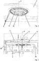
- FIGS. 2 to 4 show a first embodiment of a ventilated domestic oven, provided with an inner compartment for cooking food.
- a ventilated domestic oven provided with an inner compartment for cooking food.
- Such an oven comprises:
- the radial fan 1 is configured to take air in from the inner compartment along the direction of axis X and to expel, radially with respect to axis X, air flows directed towards said at least one resistance wire 3.
- Each resistance wire 3 which can be single or more than one, consists of either a single winding or two or more windings appropriately connected to one another.
- a support structure 4 which defines a closed housing, in which the radial fan 1 and the at least one resistance wire 3 are housed.
- the support structure 4 comprises a base 16, or a flat surface, and a protective lid 17.
- the base 16 is fixed to the upper wall 2, for example by means of screws.
- the protective lid 17 can be defined, for example, by a spherical zone, i.e. by a part of a spherical surface comprised between two parallel planes which cut the sphere or by a spherical cap surface.
- Such a protective lid 17 is provided with at least one series of first slots 14 arranged along a circumference.
- each series is arranged along a respective circumference.
- Such circumferences are preferably concentric and have a different radius from one another.
- a further air inlet slot 18 can be positioned at a central portion of the bottom of the lid, coaxial to the center of such circumferences.
- the number of the series of first and/or second slots can be varied.
- the support structure 4, radial fan 1 and at least one resistance wire 3 are preassembled so as to form a single component to be installed in the oven.
- a pipe 8 connected to a reservoir 10 outside the support structure 4 is provided inside the oven compartment, preferably but not necessarily on the support structure 4.
- a pipe is provided with a plurality of holes 9 facing towards the upper wall 2 for releasing steam.
- the pipe 8 is fed with water coming from the reservoir 10, by using a pump 21, producing steam which exits from the holes 9.
- the pipe 8 substantially circular in shape, is arranged between the at least one resistance wire 3 and the radial fan 1, coaxially to said radial fan 1.
- the pipe 8 is arranged adjacently between the single resistance wire 3 or one of the resistance wires 3 and a tubular electric resistor 7, of substantially circular shape and coaxial to the radial fan 1.
- the resistor 7 transmits heat to the pipe 8 by conduction, the pipe 8 and the resistor 7 being mechanically and thermally connected.
- the support structure 4 comprises a cavity facing towards the upper wall 2 of the compartment, having a circular bottom 5 for housing the radial fan 1 and a flared edge 6 onto which the single resistance wire 3 or the two or more resistance wires 3 are fixed by means of appropriate ceramic supports.
- the pipe 8, arranged between a resistance wire 3 and the radial fan 1, can be provided in a connection zone between the circular bottom 5 and the flared edge 6.
- the radial fan 1 is positioned so as to expel air flows, which at least partially brush the pipe 8 and the one or more resistance wires 3, and preferably also the tubular electric resistor 7, so as to heat and optimally distribute the air of the inner compartment of the oven and optimize the dispersion of steam released from the holes 9.
- the outlet sections of the bladed impeller of the radial fan 1 are arranged at a height or position corresponding at least partially to the height or position of the pipe 8, of the one or more resistance wires 3 and of the tubular electric resistor 7.
- a support structure may be provided as described for the first embodiment, comprising the base and the lid and the series of first and second slots.
- a further either radial or axial fan 12 is provided, configured to aspirate cool air from the outside of the oven and to expel air flows for cooling the electronics of the oven and of the door 22 of said oven.
- the further fan 12 is a radial fan arranged along the axis X itself and a single motor 13 is provided to actuate both the radial fan 1, which operates on the hot air of the oven and the radial cooling fan 12.
- an inner compartment for cooking food closed by a door is provided instead, the oven comprising:
- the radial fan 1 is configured to take air in from the inner compartment along the direction of axis Y and to expel, radially with respect to axis Y, air flows directed towards said at least one resistance wire.
- the resistance wire 3 which can be one or more than one, consists of either a single winding or two or more windings appropriately connected together.
- a support structure 4 of the radial fan 1' and of the at least one resistance wire 3 is provided.
- a pipe 8 connected to a reservoir 10 outside the support structure 4 is provided within the compartment of the oven, preferably but not necessarily on the support structure 4.
- Such a pipe is provided with a plurality of holes 9 (not shown in Figure 8 ) at least partially facing towards the upper wall 2 of the compartment to release steam.
- the pipe 8 is fed with water coming from the reservoir 10, by using a pump 21, producing steam which exits from the holes 9.
- the pipe 8 substantially circular in shape, is arranged between the at least one resistance wire 3 and the radial fan 1', coaxially to said radial fan 1'.
- the pipe 8 is arranged adjacently between the single resistance wire 3 or one of the resistance wires 3 and a tubular electric resistor 7, of substantially circular shape and coaxial to the radial fan 1'.
- the resistor 7 transmits heat to the pipe 8 by conduction, the pipe 8 and the resistor 7 being mechanically and thermally connected.
- the support structure 4 comprises a cavity facing towards the rear wall 20 of the compartment, having a circular bottom 5 for housing the radial fan 1' and a flared edge 6 onto which the single resistance wire 3 or the two or more resistance wires 3 are fixed by means of appropriate ceramic supports.
- the pipe 8, arranged between the one or more resistance wires 3 and the radial fan 1', can be provided in a connection zone between the circular bottom 5 and the flared edge 6.
- the radial fan 1' is positioned so as to expel air flows, which at least partially brush the pipe 8 and the one or more resistance wires 3, and preferably also the tubular electric resistor 7, so as to heat and distribute in optimal manner the air of the inner compartment of the oven and optimize the dispersion of steam released from the holes 9.
- the outlet sections of the bladed impeller of the radial fan 1' are arranged at least partially facing the pipe 8, the one or more resistance wires 3 and the tubular electric resistor 7.
- a further either radial or axial fan 12 is provided in such a cooling cavity 11, which fan is configured to aspirate cool air from the outside of the oven and to expel air flows for cooling the electronics of the oven and of the door 22 of said oven.
- a support structure can be provided as described for the first embodiment, comprising the base and the lid and the series of first and second slots.
Description
- The present invention relates to a domestic oven for cooking food.
- Ventilated domestic ovens are already known, i.e. ovens which provide the possibility of a so-called ventilated cooking system which allows to uniform the temperature inside the oven.
- The ventilation is performed by an axial fan which conveys air onto an electric resistor positioned near the fan itself. The air is heated, runs along the walls of the compartment and, once reached the door of the oven, is aspirated by the fan center to be pushed onto the electric resistor again.
- In the domestic ovens of the prior art the fan-resistor system is positioned on the wall opposite to the cavity door, as diagrammatically shown in
Fig. 1 . Disadvantageously, this configuration may generate an asymmetric air flow which leads to an imbalanced heat distribution at the walls of the oven compartment. Furthermore, the fan, the electric resistor and the resistor support are disadvantageously assembled in the cavity of the oven at different times and according to different methods. - The need is thus felt to make a domestic oven which allows to overcome the aforesaid drawbacks.
- Document
US3529582 discloses a domestic oven wherein the fan-resistor system is arranged at the top of the cavity of the oven. - Document
EP1550828 discloses a domestic oven provided with a steam generating unit. - It is the main object of the present invention to make a domestic oven which allows to improve ventilation so as to uniform the heat distribution within the compartment.
- Another object of the invention is to make a domestic oven which also allows to improve the steam distribution inside the compartment if a steam diffusion device is provided inside the oven.
- The present invention thus aims to reach the object discussed above by making a domestic oven according to
claim 1. - Advantageously, the radial fan is positioned only on the roof of the cavity or inner compartment of the oven in the oven of the invention.
- A further advantage is that one or more spiral coiled resistance wires are provided near the roof, coaxially outside the radial fan. The use of these simple resistance wires instead of the classic tubular serpentine resistor allows to have a smaller mass and to improve system efficiency. In a preferred variant, there are only two resistance wires, arranged along a respective circumference, coaxially to the outside of the radial fan.
- Forced ventilation occurs because the air flows let out from the radial fan are directed onto the resistance wires, are heated and run along the roof and then downwards along the side walls of the compartment to reach the position of the tray or vessel containing the food. From the center of the tray, a resulting flow of air will go upwards again towards the center of the radial fan and the cycle will be repeated.
- In an advantageous variant, the radial fan, positioned on the roof, can be coupled to the fan which cools the electronics and the door of the oven, a single motor being provided for both fans.
- According to an alternative embodiment which is not part of the invention, the oven has an inner compartment for cooking food, closed by a door, the oven comprising:
- a radial fan, defining and revolving about an axis Y, exclusively arranged on a rear wall of the inner compartment, opposite to the oven door, the axis Y being substantially perpendicular to said rear wall,
- at least one spiral coiled resistance wire, arranged along a circumference, coaxially outside said radial fan,
- Preferably, in all embodiments and possible variants, the support structure comprises a flat surface and a protective lid, which jointly define a closed housing, inside which the at least one resistance wire and the fan are provided. Preferably, the protective lid is provided with a least one series of first slots arranged peripherally, or laterally, along a respective circumference, at the at least one resistance wire for the radial ejection of air flows crossing said at least one resistance wire. In addition to the at least one series of first slots, the lid may also be provided with at least one series of second slots arranged centrally along a respective circumference, at the radial fan, for the passage of aspirated air from the inner compartment. By virtue of the series of first slots and the series of second slots, and considering that they are obtained in a closed housing, the air can pass only through the first and second slots, determining an optimized flow and heating.
- Furthermore, one or more series of first slots can be provided arranged, for example, on circumferences at different axial heights along the rotation axis of the fan. Furthermore, the cover can have one or more series of second slots, arranged, for example, along respective concentric circumferences of different radius.
- According to an aspect, according to the invention the fan, the electric resistor and the support/protective lid of the resistor are mutually preassembled and form an integrated system, i.e. defining a single assembled component, which can be subsequently fitted in the oven cavity more simply and cost-effectively than in the prior art. Furthermore, there are advantages in terms of robustness and compactness by providing a preassembled component.
- The dependent claims describe preferred embodiments of the invention.
- Further features and advantages of the present invention will be more apparent in light of the detailed description of a preferred, but not exclusive, embodiment, of a domestic oven illustrated by way of non-limitative example, with reference to the accompanying drawings, in which:
-
Fig. 1 is a diagram of an oven solution according to the prior art; -
Fig. 2 is a perspective view of a first embodiment of the oven according to the invention; -
Fig. 3 is an enlargement of the view inFig. 2 ; -
Fig. 4 is a cross section of part of the oven inFig. 1 ; -
Fig. 5 is a perspective view of some components of the oven of the invention; -
Fig. 6 is the same view as inFig. 5 , with one component less for better visibility of the other components; -
Fig. 7 is a view of a second embodiment of the oven according to the invention; -
Fig. 8 is a view of a third embodiment of the oven which is not part of the invention. -
Fig. 9 is a perspective view of a support structure according to the invention, which can be used in all embodiments. - The same reference numbers in the figures identify the same members.
- Figures from 2 to 4 show a first embodiment of a ventilated domestic oven, provided with an inner compartment for cooking food. Such an oven comprises:
- a
radial fan 1, defining and revolving about an axis X, exclusively arranged on anupper wall 2 of the inner compartment, the axis X being substantially perpendicular to saidupper wall 2; - and at least one spiral coiled
resistance wire 3, arranged along a respective circumference, coaxially outside saidradial fan 1. - The
radial fan 1 is configured to take air in from the inner compartment along the direction of axis X and to expel, radially with respect to axis X, air flows directed towards said at least oneresistance wire 3. - Each
resistance wire 3, which can be single or more than one, consists of either a single winding or two or more windings appropriately connected to one another. - A
support structure 4 is provided, which defines a closed housing, in which theradial fan 1 and the at least oneresistance wire 3 are housed. Preferably, as shown inFig. 9 , for example, thesupport structure 4 comprises abase 16, or a flat surface, and aprotective lid 17. Thebase 16 is fixed to theupper wall 2, for example by means of screws. Theprotective lid 17 can be defined, for example, by a spherical zone, i.e. by a part of a spherical surface comprised between two parallel planes which cut the sphere or by a spherical cap surface. Such aprotective lid 17 is provided with at least one series offirst slots 14 arranged along a circumference. Near theradial fan 1, preferably on the bottom of the lid, distal from thebase 16, three series ofsecond slots 15 are provided, wherein each series is arranged along a respective circumference. Such circumferences are preferably concentric and have a different radius from one another. A furtherair inlet slot 18 can be positioned at a central portion of the bottom of the lid, coaxial to the center of such circumferences. The number of the series of first and/or second slots can be varied. - Preferably, the
support structure 4,radial fan 1 and at least oneresistance wire 3 are preassembled so as to form a single component to be installed in the oven. - According to a second embodiment of the oven of the invention, shown in Figures from 5 to 7, a
pipe 8 connected to areservoir 10 outside thesupport structure 4 is provided inside the oven compartment, preferably but not necessarily on thesupport structure 4. Such a pipe is provided with a plurality ofholes 9 facing towards theupper wall 2 for releasing steam. In practice, thepipe 8 is fed with water coming from thereservoir 10, by using apump 21, producing steam which exits from theholes 9. - The
pipe 8, substantially circular in shape, is arranged between the at least oneresistance wire 3 and theradial fan 1, coaxially to saidradial fan 1. - Advantageously, in order to make the formation of steam more rapid, the
pipe 8 is arranged adjacently between thesingle resistance wire 3 or one of theresistance wires 3 and a tubularelectric resistor 7, of substantially circular shape and coaxial to theradial fan 1. Theresistor 7 transmits heat to thepipe 8 by conduction, thepipe 8 and theresistor 7 being mechanically and thermally connected. - In a preferred variant, the
support structure 4 comprises a cavity facing towards theupper wall 2 of the compartment, having acircular bottom 5 for housing theradial fan 1 and a flarededge 6 onto which thesingle resistance wire 3 or the two ormore resistance wires 3 are fixed by means of appropriate ceramic supports. Thepipe 8, arranged between aresistance wire 3 and theradial fan 1, can be provided in a connection zone between thecircular bottom 5 and the flarededge 6. - Advantageously, the
radial fan 1 is positioned so as to expel air flows, which at least partially brush thepipe 8 and the one ormore resistance wires 3, and preferably also the tubularelectric resistor 7, so as to heat and optimally distribute the air of the inner compartment of the oven and optimize the dispersion of steam released from theholes 9. This means that the outlet sections of the bladed impeller of theradial fan 1 are arranged at a height or position corresponding at least partially to the height or position of thepipe 8, of the one ormore resistance wires 3 and of the tubularelectric resistor 7. Also in this embodiment, a support structure may be provided as described for the first embodiment, comprising the base and the lid and the series of first and second slots. - In both the first and the second embodiments, described above, there is a
cooling cavity 11, arranged over theupper wall 2 of the inner compartment of the oven. In such acooling cavity 11, a further either radial oraxial fan 12 is provided, configured to aspirate cool air from the outside of the oven and to expel air flows for cooling the electronics of the oven and of thedoor 22 of said oven. In a preferred variant, thefurther fan 12 is a radial fan arranged along the axis X itself and asingle motor 13 is provided to actuate both theradial fan 1, which operates on the hot air of the oven and theradial cooling fan 12. - In a third embodiment of the oven which is not part of the invention, shown in
Figure 8 , an inner compartment for cooking food closed by a door is provided instead, the oven comprising: - a radial fan 1', defining and revolving about an axis Y (perpendicular to the sheet in
Fig. 8 ), exclusively arranged on arear wall 20 of the inner compartment, opposite to the oven door, the axis Y being substantially perpendicular to saidrear wall 20, - and at least one spiral coiled
resistance wire 3, arranged in a circumference, coaxially outside the radial fan 1'. - The
radial fan 1 is configured to take air in from the inner compartment along the direction of axis Y and to expel, radially with respect to axis Y, air flows directed towards said at least one resistance wire. - The components of
Fig. 8 , indicated with the same reference numbers present in Figures from 2 to 7, are identical to the corresponding components in the preceding figures, unless otherwise explicitly mentioned. - The
resistance wire 3, which can be one or more than one, consists of either a single winding or two or more windings appropriately connected together. - A
support structure 4 of the radial fan 1' and of the at least oneresistance wire 3 is provided. Apipe 8 connected to areservoir 10 outside thesupport structure 4 is provided within the compartment of the oven, preferably but not necessarily on thesupport structure 4. Such a pipe is provided with a plurality of holes 9 (not shown inFigure 8 ) at least partially facing towards theupper wall 2 of the compartment to release steam. In practice, thepipe 8 is fed with water coming from thereservoir 10, by using apump 21, producing steam which exits from theholes 9. - The
pipe 8, substantially circular in shape, is arranged between the at least oneresistance wire 3 and the radial fan 1', coaxially to said radial fan 1'. - Advantageously, in order to make the formation of steam more rapid, the
pipe 8 is arranged adjacently between thesingle resistance wire 3 or one of theresistance wires 3 and a tubularelectric resistor 7, of substantially circular shape and coaxial to the radial fan 1'. Theresistor 7 transmits heat to thepipe 8 by conduction, thepipe 8 and theresistor 7 being mechanically and thermally connected. - In a preferred variant, the
support structure 4 comprises a cavity facing towards therear wall 20 of the compartment, having acircular bottom 5 for housing the radial fan 1' and a flarededge 6 onto which thesingle resistance wire 3 or the two ormore resistance wires 3 are fixed by means of appropriate ceramic supports. Thepipe 8, arranged between the one ormore resistance wires 3 and the radial fan 1', can be provided in a connection zone between thecircular bottom 5 and the flarededge 6. - Advantageously, the radial fan 1' is positioned so as to expel air flows, which at least partially brush the
pipe 8 and the one ormore resistance wires 3, and preferably also the tubularelectric resistor 7, so as to heat and distribute in optimal manner the air of the inner compartment of the oven and optimize the dispersion of steam released from theholes 9. This means that the outlet sections of the bladed impeller of the radial fan 1' are arranged at least partially facing thepipe 8, the one ormore resistance wires 3 and the tubularelectric resistor 7. - A cooling
cavity 11, arranged over theupper wall 2 of the inner compartment of the oven, is provided also in this third embodiment. A further either radial oraxial fan 12 is provided in such acooling cavity 11, which fan is configured to aspirate cool air from the outside of the oven and to expel air flows for cooling the electronics of the oven and of thedoor 22 of said oven. Furthermore, also in this embodiment, a support structure can be provided as described for the first embodiment, comprising the base and the lid and the series of first and second slots.
Claims (9)
- A domestic oven provided with an inner compartment for cooking food, the oven comprising:- a radial fan (1), defining and revolving about an axis (X), exclusively arranged on an upper wall (2) of said inner compartment,- at least one spiral coiled resistance wire (3), arranged along a respective circumference, coaxially outside said radial fan (1),wherein said radial fan (1) is adapted to take air in from the inner compartment along the direction of axis (X) and to expel, radially with respect to axis (X), air flows directed towards said at least one resistance wire (3),
wherein a support structure (4) is provided to support the radial fan (1) and said at least one resistance wire (3),
wherein said support structure is a housing (4), in which the radial fan (1) and the at least one resistance wire (3) are assembled, said housing (4) being fixed to the upper wall (2) of the inner compartment,
characterized in that a pipe (8) is provided in the housing, the pipe (8) being connected to a reservoir (10) outside the support structure (4) and provided with a plurality of holes (9) facing the upper wall (2) for releasing steam,
wherein said pipe (8) is arranged between said at least one resistance wire (3) and the radial fan (1), coaxially to said radial fan (1). - An oven according to claim 1, wherein said closed housing (4) comprises a flat surface (16) fixed to the upper wall (2) and a protective lid (17), integrally fixed to said flat surface (16) and provided with at least one series of first slots (14) peripherally arranged along a respective circumference, at the at least one resistance wire (3), for the radial ejection of the air flows crossing said at least one resistance wire (3).
- An oven according to claim 2, wherein said protective cover (17) is provided with at least one series of second slots (15) centrally arranged along a respective circumference, at the radial fan (1), for the passage of air aspirated from the inner compartment.
- An oven according to claim 1, wherein said at least one resistance wire (3) consists of either a single winding or two or more windings connected together, respectively.
- An oven according to claim 1, wherein said pipe (8) is adjacently arranged between said at least one resistance wire (3) and a tubular electric resistor (7), coaxial to said radial fan (1).
- An oven according to claim 1 or 5, wherein the radial fan (1) is placed so as to expel air flows, which at least partially brush the pipe (8), the at least one resistance wire (3) and, preferably, also the tubular electric resistor (7).
- An oven according to any one of the preceding claims, wherein there is provided a cooling cavity (11) placed over the upper wall (2) of the inner compartment of the oven, and provided with a further, either radial or axial fan (12), adapted to take air in from outside the oven and to expel air flows to cool the electronics of the oven and the door of said oven.
- An oven according to claim 7, wherein the further fan (12) is radial and arranged along said axis (X) and there is provided a single motor (13) to actuate both the radial fan (1) and said further radial fan (12).
- An oven according to any one of the preceding claims, wherein there are provided two spiral coiled resistance wires (3) arranged along respective coaxial circumferences outside said radial fan (1).
Applications Claiming Priority (2)
| Application Number | Priority Date | Filing Date | Title |
|---|---|---|---|
| ITRM20140430 | 2014-07-31 | ||
| PCT/IB2015/055816 WO2016016860A1 (en) | 2014-07-31 | 2015-07-31 | Domestic oven |
Publications (2)
| Publication Number | Publication Date |
|---|---|
| EP3194854A1 EP3194854A1 (en) | 2017-07-26 |
| EP3194854B1 true EP3194854B1 (en) | 2018-10-24 |
Family
ID=51799241
Family Applications (1)
| Application Number | Title | Priority Date | Filing Date |
|---|---|---|---|
| EP15760277.2A Active EP3194854B1 (en) | 2014-07-31 | 2015-07-31 | Domestic oven |
Country Status (2)
| Country | Link |
|---|---|
| EP (1) | EP3194854B1 (en) |
| WO (1) | WO2016016860A1 (en) |
Families Citing this family (2)
| Publication number | Priority date | Publication date | Assignee | Title |
|---|---|---|---|---|
| WO2021246975A1 (en) * | 2020-06-02 | 2021-12-09 | Femas Metal San. Ve Tic. A.S. | Oven with steam assembly |
| DE102020132482A1 (en) * | 2020-12-07 | 2022-06-09 | Welbilt Deutschland GmbH | Cooking device, in particular commercial cooking device |
Family Cites Families (13)
| Publication number | Priority date | Publication date | Assignee | Title |
|---|---|---|---|---|
| US3379189A (en) * | 1966-08-08 | 1968-04-23 | Gen Electric | Forced convection oven |
| US3529582A (en) * | 1968-12-09 | 1970-09-22 | Gen Electric | Self-cleaning forced convection oven |
| US3828760A (en) * | 1973-05-23 | 1974-08-13 | Lca Corp | Oven |
| FR2614976B1 (en) * | 1987-05-06 | 1990-03-09 | Seb Sa | ELECTRIC OVEN FOR COOKING FOODS COMPRISING A STEAM GENERATOR |
| DE3941322A1 (en) * | 1989-12-14 | 1991-06-20 | Bosch Siemens Hausgeraete | Steam cooking device mounted on wall of oven - ensures humidification of cooking space by evapn. of water in container surrounded by electric heating coil |
| US5485780A (en) * | 1993-02-26 | 1996-01-23 | Food Automation Service Techniques, Inc. | Rotisserie oven |
| DE19812465C5 (en) * | 1998-03-23 | 2011-06-01 | Miwe Michael Wenz Gmbh | Oven with steam generator |
| US20040089648A1 (en) * | 2002-07-29 | 2004-05-13 | Griffey Dean J. | Open coil heater element convection system for convection ovens and the like |
| KR101041071B1 (en) * | 2003-12-30 | 2011-06-13 | 삼성전자주식회사 | Heating cooker |
| KR20060006472A (en) * | 2004-07-16 | 2006-01-19 | 삼성전자주식회사 | Heating cooker |
| KR101323325B1 (en) * | 2006-11-15 | 2013-10-29 | 엘지전자 주식회사 | Cooking Device |
| DE102012200704A1 (en) * | 2012-01-19 | 2013-07-25 | E.G.O. Elektro-Gerätebau GmbH | Cooking device and method for operating a cooking device |
| EP2636955B1 (en) * | 2012-03-08 | 2016-11-16 | Electrolux Home Products Corporation N.V. | A cooking oven provided for heat transfer by convection |
-
2015
- 2015-07-31 WO PCT/IB2015/055816 patent/WO2016016860A1/en active Application Filing
- 2015-07-31 EP EP15760277.2A patent/EP3194854B1/en active Active
Non-Patent Citations (1)
| Title |
|---|
| None * |
Also Published As
| Publication number | Publication date |
|---|---|
| EP3194854A1 (en) | 2017-07-26 |
| WO2016016860A1 (en) | 2016-02-04 |
Similar Documents
| Publication | Publication Date | Title |
|---|---|---|
| JP6211659B2 (en) | Apparatus for cooking food and air guide member therefor | |
| CN106618245B (en) | Air guide member for an apparatus for preparing food ingredients using an air flow | |
| US10371391B2 (en) | Cooking oven provided for heat transfer by convection | |
| EP3038504B1 (en) | Cooking machine | |
| RU2473844C2 (en) | Cooking device and air direction element used in it | |
| CN107595153B (en) | Heating pot capable of improving heating efficiency | |
| US11353220B2 (en) | Direct-heating fan oven | |
| UA107094C2 (en) | CENTRAL CEILING FAN | |
| JP2013537297A (en) | Equipment for making food | |
| US20130284161A1 (en) | Oven appliance with features for selecting convection air flow direction | |
| CN111904293B (en) | Cooking device | |
| EP3194854B1 (en) | Domestic oven | |
| JP5666040B1 (en) | Cooker | |
| CN205548371U (en) | Cooking utensil | |
| KR102355783B1 (en) | electric cooker | |
| JP6593961B2 (en) | Cooker | |
| KR101411760B1 (en) | Electric oven | |
| CN112515493A (en) | Cooking utensil | |
| CN218635844U (en) | Air frying pan | |
| US11060737B2 (en) | Alternate convection system in home cooking appliances | |
| CN218304493U (en) | Circulation type steaming and baking oven | |
| CN211722845U (en) | Hot air duct structure, pot cover and air fryer | |
| CN214484286U (en) | Cooking utensil | |
| CN218044812U (en) | Steam air fryer | |
| WO2015092642A1 (en) | Direct-heating fan oven |
Legal Events
| Date | Code | Title | Description |
|---|---|---|---|
| STAA | Information on the status of an ep patent application or granted ep patent |
Free format text: STATUS: THE INTERNATIONAL PUBLICATION HAS BEEN MADE |
|
| PUAI | Public reference made under article 153(3) epc to a published international application that has entered the european phase |
Free format text: ORIGINAL CODE: 0009012 |
|
| STAA | Information on the status of an ep patent application or granted ep patent |
Free format text: STATUS: REQUEST FOR EXAMINATION WAS MADE |
|
| 17P | Request for examination filed |
Effective date: 20170224 |
|
| AK | Designated contracting states |
Kind code of ref document: A1 Designated state(s): AL AT BE BG CH CY CZ DE DK EE ES FI FR GB GR HR HU IE IS IT LI LT LU LV MC MK MT NL NO PL PT RO RS SE SI SK SM TR |
|
| AX | Request for extension of the european patent |
Extension state: BA ME |
|
| DAV | Request for validation of the european patent (deleted) | ||
| DAX | Request for extension of the european patent (deleted) | ||
| GRAP | Despatch of communication of intention to grant a patent |
Free format text: ORIGINAL CODE: EPIDOSNIGR1 |
|
| STAA | Information on the status of an ep patent application or granted ep patent |
Free format text: STATUS: GRANT OF PATENT IS INTENDED |
|
| INTG | Intention to grant announced |
Effective date: 20180504 |
|
| GRAS | Grant fee paid |
Free format text: ORIGINAL CODE: EPIDOSNIGR3 |
|
| GRAA | (expected) grant |
Free format text: ORIGINAL CODE: 0009210 |
|
| STAA | Information on the status of an ep patent application or granted ep patent |
Free format text: STATUS: THE PATENT HAS BEEN GRANTED |
|
| AK | Designated contracting states |
Kind code of ref document: B1 Designated state(s): AL AT BE BG CH CY CZ DE DK EE ES FI FR GB GR HR HU IE IS IT LI LT LU LV MC MK MT NL NO PL PT RO RS SE SI SK SM TR |
|
| REG | Reference to a national code |
Ref country code: CH Ref legal event code: EP |
|
| REG | Reference to a national code |
Ref country code: IE Ref legal event code: FG4D |
|
| REG | Reference to a national code |
Ref country code: AT Ref legal event code: REF Ref document number: 1057137 Country of ref document: AT Kind code of ref document: T Effective date: 20181115 |
|
| REG | Reference to a national code |
Ref country code: DE Ref legal event code: R096 Ref document number: 602015018748 Country of ref document: DE |
|
| REG | Reference to a national code |
Ref country code: NL Ref legal event code: MP Effective date: 20181024 |
|
| REG | Reference to a national code |
Ref country code: LT Ref legal event code: MG4D |
|
| REG | Reference to a national code |
Ref country code: AT Ref legal event code: MK05 Ref document number: 1057137 Country of ref document: AT Kind code of ref document: T Effective date: 20181024 |
|
| PG25 | Lapsed in a contracting state [announced via postgrant information from national office to epo] |
Ref country code: NL Free format text: LAPSE BECAUSE OF FAILURE TO SUBMIT A TRANSLATION OF THE DESCRIPTION OR TO PAY THE FEE WITHIN THE PRESCRIBED TIME-LIMIT Effective date: 20181024 |
|
| PG25 | Lapsed in a contracting state [announced via postgrant information from national office to epo] |
Ref country code: ES Free format text: LAPSE BECAUSE OF FAILURE TO SUBMIT A TRANSLATION OF THE DESCRIPTION OR TO PAY THE FEE WITHIN THE PRESCRIBED TIME-LIMIT Effective date: 20181024 Ref country code: HR Free format text: LAPSE BECAUSE OF FAILURE TO SUBMIT A TRANSLATION OF THE DESCRIPTION OR TO PAY THE FEE WITHIN THE PRESCRIBED TIME-LIMIT Effective date: 20181024 Ref country code: PL Free format text: LAPSE BECAUSE OF FAILURE TO SUBMIT A TRANSLATION OF THE DESCRIPTION OR TO PAY THE FEE WITHIN THE PRESCRIBED TIME-LIMIT Effective date: 20181024 Ref country code: LV Free format text: LAPSE BECAUSE OF FAILURE TO SUBMIT A TRANSLATION OF THE DESCRIPTION OR TO PAY THE FEE WITHIN THE PRESCRIBED TIME-LIMIT Effective date: 20181024 Ref country code: IS Free format text: LAPSE BECAUSE OF FAILURE TO SUBMIT A TRANSLATION OF THE DESCRIPTION OR TO PAY THE FEE WITHIN THE PRESCRIBED TIME-LIMIT Effective date: 20190224 Ref country code: FI Free format text: LAPSE BECAUSE OF FAILURE TO SUBMIT A TRANSLATION OF THE DESCRIPTION OR TO PAY THE FEE WITHIN THE PRESCRIBED TIME-LIMIT Effective date: 20181024 Ref country code: BG Free format text: LAPSE BECAUSE OF FAILURE TO SUBMIT A TRANSLATION OF THE DESCRIPTION OR TO PAY THE FEE WITHIN THE PRESCRIBED TIME-LIMIT Effective date: 20190124 Ref country code: LT Free format text: LAPSE BECAUSE OF FAILURE TO SUBMIT A TRANSLATION OF THE DESCRIPTION OR TO PAY THE FEE WITHIN THE PRESCRIBED TIME-LIMIT Effective date: 20181024 Ref country code: AT Free format text: LAPSE BECAUSE OF FAILURE TO SUBMIT A TRANSLATION OF THE DESCRIPTION OR TO PAY THE FEE WITHIN THE PRESCRIBED TIME-LIMIT Effective date: 20181024 Ref country code: NO Free format text: LAPSE BECAUSE OF FAILURE TO SUBMIT A TRANSLATION OF THE DESCRIPTION OR TO PAY THE FEE WITHIN THE PRESCRIBED TIME-LIMIT Effective date: 20190124 |
|
| PG25 | Lapsed in a contracting state [announced via postgrant information from national office to epo] |
Ref country code: RS Free format text: LAPSE BECAUSE OF FAILURE TO SUBMIT A TRANSLATION OF THE DESCRIPTION OR TO PAY THE FEE WITHIN THE PRESCRIBED TIME-LIMIT Effective date: 20181024 Ref country code: GR Free format text: LAPSE BECAUSE OF FAILURE TO SUBMIT A TRANSLATION OF THE DESCRIPTION OR TO PAY THE FEE WITHIN THE PRESCRIBED TIME-LIMIT Effective date: 20190125 Ref country code: PT Free format text: LAPSE BECAUSE OF FAILURE TO SUBMIT A TRANSLATION OF THE DESCRIPTION OR TO PAY THE FEE WITHIN THE PRESCRIBED TIME-LIMIT Effective date: 20190224 Ref country code: AL Free format text: LAPSE BECAUSE OF FAILURE TO SUBMIT A TRANSLATION OF THE DESCRIPTION OR TO PAY THE FEE WITHIN THE PRESCRIBED TIME-LIMIT Effective date: 20181024 Ref country code: SE Free format text: LAPSE BECAUSE OF FAILURE TO SUBMIT A TRANSLATION OF THE DESCRIPTION OR TO PAY THE FEE WITHIN THE PRESCRIBED TIME-LIMIT Effective date: 20181024 |
|
| REG | Reference to a national code |
Ref country code: DE Ref legal event code: R097 Ref document number: 602015018748 Country of ref document: DE |
|
| PG25 | Lapsed in a contracting state [announced via postgrant information from national office to epo] |
Ref country code: DK Free format text: LAPSE BECAUSE OF FAILURE TO SUBMIT A TRANSLATION OF THE DESCRIPTION OR TO PAY THE FEE WITHIN THE PRESCRIBED TIME-LIMIT Effective date: 20181024 Ref country code: CZ Free format text: LAPSE BECAUSE OF FAILURE TO SUBMIT A TRANSLATION OF THE DESCRIPTION OR TO PAY THE FEE WITHIN THE PRESCRIBED TIME-LIMIT Effective date: 20181024 Ref country code: IT Free format text: LAPSE BECAUSE OF FAILURE TO SUBMIT A TRANSLATION OF THE DESCRIPTION OR TO PAY THE FEE WITHIN THE PRESCRIBED TIME-LIMIT Effective date: 20181024 |
|
| PG25 | Lapsed in a contracting state [announced via postgrant information from national office to epo] |
Ref country code: RO Free format text: LAPSE BECAUSE OF FAILURE TO SUBMIT A TRANSLATION OF THE DESCRIPTION OR TO PAY THE FEE WITHIN THE PRESCRIBED TIME-LIMIT Effective date: 20181024 Ref country code: SK Free format text: LAPSE BECAUSE OF FAILURE TO SUBMIT A TRANSLATION OF THE DESCRIPTION OR TO PAY THE FEE WITHIN THE PRESCRIBED TIME-LIMIT Effective date: 20181024 Ref country code: SM Free format text: LAPSE BECAUSE OF FAILURE TO SUBMIT A TRANSLATION OF THE DESCRIPTION OR TO PAY THE FEE WITHIN THE PRESCRIBED TIME-LIMIT Effective date: 20181024 Ref country code: EE Free format text: LAPSE BECAUSE OF FAILURE TO SUBMIT A TRANSLATION OF THE DESCRIPTION OR TO PAY THE FEE WITHIN THE PRESCRIBED TIME-LIMIT Effective date: 20181024 |
|
| PLBE | No opposition filed within time limit |
Free format text: ORIGINAL CODE: 0009261 |
|
| STAA | Information on the status of an ep patent application or granted ep patent |
Free format text: STATUS: NO OPPOSITION FILED WITHIN TIME LIMIT |
|
| 26N | No opposition filed |
Effective date: 20190725 |
|
| PG25 | Lapsed in a contracting state [announced via postgrant information from national office to epo] |
Ref country code: SI Free format text: LAPSE BECAUSE OF FAILURE TO SUBMIT A TRANSLATION OF THE DESCRIPTION OR TO PAY THE FEE WITHIN THE PRESCRIBED TIME-LIMIT Effective date: 20181024 |
|
| PG25 | Lapsed in a contracting state [announced via postgrant information from national office to epo] |
Ref country code: MC Free format text: LAPSE BECAUSE OF FAILURE TO SUBMIT A TRANSLATION OF THE DESCRIPTION OR TO PAY THE FEE WITHIN THE PRESCRIBED TIME-LIMIT Effective date: 20181024 |
|
| REG | Reference to a national code |
Ref country code: CH Ref legal event code: PL |
|
| GBPC | Gb: european patent ceased through non-payment of renewal fee |
Effective date: 20190731 |
|
| PG25 | Lapsed in a contracting state [announced via postgrant information from national office to epo] |
Ref country code: TR Free format text: LAPSE BECAUSE OF FAILURE TO SUBMIT A TRANSLATION OF THE DESCRIPTION OR TO PAY THE FEE WITHIN THE PRESCRIBED TIME-LIMIT Effective date: 20181024 |
|
| REG | Reference to a national code |
Ref country code: BE Ref legal event code: MM Effective date: 20190731 |
|
| PG25 | Lapsed in a contracting state [announced via postgrant information from national office to epo] |
Ref country code: GB Free format text: LAPSE BECAUSE OF NON-PAYMENT OF DUE FEES Effective date: 20190731 |
|
| PG25 | Lapsed in a contracting state [announced via postgrant information from national office to epo] |
Ref country code: CH Free format text: LAPSE BECAUSE OF NON-PAYMENT OF DUE FEES Effective date: 20190731 Ref country code: LU Free format text: LAPSE BECAUSE OF NON-PAYMENT OF DUE FEES Effective date: 20190731 Ref country code: BE Free format text: LAPSE BECAUSE OF NON-PAYMENT OF DUE FEES Effective date: 20190731 Ref country code: LI Free format text: LAPSE BECAUSE OF NON-PAYMENT OF DUE FEES Effective date: 20190731 |
|
| PG25 | Lapsed in a contracting state [announced via postgrant information from national office to epo] |
Ref country code: FR Free format text: LAPSE BECAUSE OF NON-PAYMENT OF DUE FEES Effective date: 20190731 |
|
| PG25 | Lapsed in a contracting state [announced via postgrant information from national office to epo] |
Ref country code: IE Free format text: LAPSE BECAUSE OF NON-PAYMENT OF DUE FEES Effective date: 20190731 |
|
| PG25 | Lapsed in a contracting state [announced via postgrant information from national office to epo] |
Ref country code: CY Free format text: LAPSE BECAUSE OF FAILURE TO SUBMIT A TRANSLATION OF THE DESCRIPTION OR TO PAY THE FEE WITHIN THE PRESCRIBED TIME-LIMIT Effective date: 20181024 |
|
| PG25 | Lapsed in a contracting state [announced via postgrant information from national office to epo] |
Ref country code: MT Free format text: LAPSE BECAUSE OF FAILURE TO SUBMIT A TRANSLATION OF THE DESCRIPTION OR TO PAY THE FEE WITHIN THE PRESCRIBED TIME-LIMIT Effective date: 20181024 Ref country code: HU Free format text: LAPSE BECAUSE OF FAILURE TO SUBMIT A TRANSLATION OF THE DESCRIPTION OR TO PAY THE FEE WITHIN THE PRESCRIBED TIME-LIMIT; INVALID AB INITIO Effective date: 20150731 |
|
| PG25 | Lapsed in a contracting state [announced via postgrant information from national office to epo] |
Ref country code: MK Free format text: LAPSE BECAUSE OF FAILURE TO SUBMIT A TRANSLATION OF THE DESCRIPTION OR TO PAY THE FEE WITHIN THE PRESCRIBED TIME-LIMIT Effective date: 20181024 |
|
| P01 | Opt-out of the competence of the unified patent court (upc) registered |
Effective date: 20230525 |
|
| PGFP | Annual fee paid to national office [announced via postgrant information from national office to epo] |
Ref country code: DE Payment date: 20230719 Year of fee payment: 9 |