EP3194726B1 - Gasturbinenschaufel mit integriertem flüssigkeitskanal für eintrittskanten- und spitzenkühlung und kernstruktur zur herstellung einer derartigen schaufel - Google Patents
Gasturbinenschaufel mit integriertem flüssigkeitskanal für eintrittskanten- und spitzenkühlung und kernstruktur zur herstellung einer derartigen schaufel Download PDFInfo
- Publication number
- EP3194726B1 EP3194726B1 EP14777462.4A EP14777462A EP3194726B1 EP 3194726 B1 EP3194726 B1 EP 3194726B1 EP 14777462 A EP14777462 A EP 14777462A EP 3194726 B1 EP3194726 B1 EP 3194726B1
- Authority
- EP
- European Patent Office
- Prior art keywords
- leading edge
- airfoil
- passage
- section
- cooling
- Prior art date
- Legal status (The legal status is an assumption and is not a legal conclusion. Google has not performed a legal analysis and makes no representation as to the accuracy of the status listed.)
- Active
Links
Images


Classifications
-
- F—MECHANICAL ENGINEERING; LIGHTING; HEATING; WEAPONS; BLASTING
- F01—MACHINES OR ENGINES IN GENERAL; ENGINE PLANTS IN GENERAL; STEAM ENGINES
- F01D—NON-POSITIVE DISPLACEMENT MACHINES OR ENGINES, e.g. STEAM TURBINES
- F01D5/00—Blades; Blade-carrying members; Heating, heat-insulating, cooling or antivibration means on the blades or the members
- F01D5/12—Blades
- F01D5/14—Form or construction
- F01D5/18—Hollow blades, i.e. blades with cooling or heating channels or cavities; Heating, heat-insulating or cooling means on blades
- F01D5/187—Convection cooling
-
- F—MECHANICAL ENGINEERING; LIGHTING; HEATING; WEAPONS; BLASTING
- F01—MACHINES OR ENGINES IN GENERAL; ENGINE PLANTS IN GENERAL; STEAM ENGINES
- F01D—NON-POSITIVE DISPLACEMENT MACHINES OR ENGINES, e.g. STEAM TURBINES
- F01D25/00—Component parts, details, or accessories, not provided for in, or of interest apart from, other groups
- F01D25/08—Cooling; Heating; Heat-insulation
- F01D25/12—Cooling
-
- F—MECHANICAL ENGINEERING; LIGHTING; HEATING; WEAPONS; BLASTING
- F01—MACHINES OR ENGINES IN GENERAL; ENGINE PLANTS IN GENERAL; STEAM ENGINES
- F01D—NON-POSITIVE DISPLACEMENT MACHINES OR ENGINES, e.g. STEAM TURBINES
- F01D9/00—Stators
- F01D9/02—Nozzles; Nozzle boxes; Stator blades; Guide conduits, e.g. individual nozzles
-
- F—MECHANICAL ENGINEERING; LIGHTING; HEATING; WEAPONS; BLASTING
- F05—INDEXING SCHEMES RELATING TO ENGINES OR PUMPS IN VARIOUS SUBCLASSES OF CLASSES F01-F04
- F05D—INDEXING SCHEME FOR ASPECTS RELATING TO NON-POSITIVE-DISPLACEMENT MACHINES OR ENGINES, GAS-TURBINES OR JET-PROPULSION PLANTS
- F05D2220/00—Application
- F05D2220/30—Application in turbines
- F05D2220/32—Application in turbines in gas turbines
-
- F—MECHANICAL ENGINEERING; LIGHTING; HEATING; WEAPONS; BLASTING
- F05—INDEXING SCHEMES RELATING TO ENGINES OR PUMPS IN VARIOUS SUBCLASSES OF CLASSES F01-F04
- F05D—INDEXING SCHEME FOR ASPECTS RELATING TO NON-POSITIVE-DISPLACEMENT MACHINES OR ENGINES, GAS-TURBINES OR JET-PROPULSION PLANTS
- F05D2240/00—Components
- F05D2240/20—Rotors
- F05D2240/30—Characteristics of rotor blades, i.e. of any element transforming dynamic fluid energy to or from rotational energy and being attached to a rotor
- F05D2240/303—Characteristics of rotor blades, i.e. of any element transforming dynamic fluid energy to or from rotational energy and being attached to a rotor related to the leading edge of a rotor blade
-
- F—MECHANICAL ENGINEERING; LIGHTING; HEATING; WEAPONS; BLASTING
- F05—INDEXING SCHEMES RELATING TO ENGINES OR PUMPS IN VARIOUS SUBCLASSES OF CLASSES F01-F04
- F05D—INDEXING SCHEME FOR ASPECTS RELATING TO NON-POSITIVE-DISPLACEMENT MACHINES OR ENGINES, GAS-TURBINES OR JET-PROPULSION PLANTS
- F05D2250/00—Geometry
- F05D2250/20—Three-dimensional
- F05D2250/25—Three-dimensional helical
-
- F—MECHANICAL ENGINEERING; LIGHTING; HEATING; WEAPONS; BLASTING
- F05—INDEXING SCHEMES RELATING TO ENGINES OR PUMPS IN VARIOUS SUBCLASSES OF CLASSES F01-F04
- F05D—INDEXING SCHEME FOR ASPECTS RELATING TO NON-POSITIVE-DISPLACEMENT MACHINES OR ENGINES, GAS-TURBINES OR JET-PROPULSION PLANTS
- F05D2260/00—Function
- F05D2260/20—Heat transfer, e.g. cooling
- F05D2260/201—Heat transfer, e.g. cooling by impingement of a fluid
-
- F—MECHANICAL ENGINEERING; LIGHTING; HEATING; WEAPONS; BLASTING
- F05—INDEXING SCHEMES RELATING TO ENGINES OR PUMPS IN VARIOUS SUBCLASSES OF CLASSES F01-F04
- F05D—INDEXING SCHEME FOR ASPECTS RELATING TO NON-POSITIVE-DISPLACEMENT MACHINES OR ENGINES, GAS-TURBINES OR JET-PROPULSION PLANTS
- F05D2260/00—Function
- F05D2260/20—Heat transfer, e.g. cooling
- F05D2260/221—Improvement of heat transfer
- F05D2260/2212—Improvement of heat transfer by creating turbulence
Definitions
- the present invention relates to a cooling system for use in an airfoil of a turbine engine, and more particularly, to an integrated leading edge and tip cooling fluid passage and core used for forming the same.
- compressed air discharged from a compressor section and fuel introduced from a source of fuel are mixed together and burned in a combustion section, creating combustion products defining a high temperature working gas.
- the working gas is directed through a hot gas path in a turbine section of the engine, where the working gas expands to provide rotation of a turbine rotor.
- the turbine rotor may be linked to an electric generator, wherein the rotation of the turbine rotor can be used to produce electricity in the generator.
- DE 10 2014 100 085 A1 discloses a core structure used to form a cooling configuration in a gas turbine engine airfoil comprising: a first core element including a leading edge section and a tip section integral with the leading edge section.
- US 6 431 832 B1 discloses an air foil for use in a gas turbine engine, said air foil having a leading edge, a trailing edge, a pressure side, a suction side, a peripheral wall having an inner surface and an outer surface.
- GB 2 395 232 A discloses a turbine component such as a blade or vane, the component comprising a 5 coolant passage and a cooling chamber connected by an injection passage, the cooling chamber including flow guide means associated with the injection passage to cause flow in a spiral coolant flow path within the chamber.
- US 2010/139903 A1 discloses a hollow passage in a machine element for enhancing the heat exchanging properties between the machine element and a fluid flowing through the hollow passage; the hollow passage comprising a helicoidal groove.
- the present invention provides a core structure used to form a cooling configuration in a gas turbine engine airfoil according to claim 1, and an airfoil for a gas turbine engine according to claim 10.
- a core structure used to form a cooling configuration in a gas turbine engine airfoil comprises a first core element including a leading edge section, a tip section integral with the leading edge section, and a turn section integral with the leading edge and tip sections and joining the leading edge and tip sections.
- the first core element is adapted to be used to form a leading edge cooling circuit in a gas turbine engine airfoil.
- the leading edge cooling circuit includes a cooling fluid passage comprising a leading edge portion formed by the first core element leading edge section, a tip portion formed by the first core element tip section, and a turn portion formed by the first core element turn section.
- the leading edge portion extends radially through the airfoil adjacent to a leading edge of the airfoil, the tip portion extends chordally from adjacent to the leading edge of the airfoil to adjacent to a trailing edge of the airfoil, and the turn portion facilitates fluid communication between the leading edge portion and the tip portion.
- Each of the leading edge portion, the tip portion, and the turn portion of the cooling fluid passage are adapted to be formed concurrently in the airfoil by the first core element.
- the leading edge section of the first core element includes a plurality of helical ridges extending circumferentially and radially with respect to a radial axis of the leading edge section, the ridges forming corresponding helical grooves extending into a surface of the airfoil defining an outer boundary of the leading edge portion of the cooling passage, wherein the grooves effect a helical flow pattern for cooling fluid flowing radially outwardly through the leading edge portion of the cooling passage.
- the turn section of the first core element may form the turn portion of the cooling fluid passage such that an angle between the leading edge portion and the tip portion is within a range of 90 degrees to 130 degrees.
- the core structure may further comprise a second core element integral with the first core element, the second core element including a mid-chord section used to form a mid-chord cooling circuit in the airfoil concurrently with the first core element forming the leading edge cooling circuit.
- the mid-chord section may include at least two radial mid-chord elements that form corresponding mid-chord passages of the mid-chord cooling circuit, the mid-chord passages extending generally radially through a mid-chord portion of the airfoil.
- the second core element may further include a trailing edge section integral with the mid-chord section, the trailing edge section used to form a trailing edge cooling circuit in the airfoil concurrently with the mid-chord section forming the mid-chord cooling circuit.
- the leading edge section of the first core element may include first and second radial leading edge elements that form corresponding first and second leading edge passages of the leading edge cooling circuit.
- the core structure may further comprise a plurality of transition elements extending between the first and second radial leading edge elements, wherein the transition elements are used to form a plurality of transition passages in the airfoil providing fluid communication from the first leading edge passage to the second leading edge passage, and wherein cooling fluid entering the second leading edge passage from the first leading edge passage through the transition passages impinges on a surface of the airfoil defining an outer boundary of the second leading edge passage to provide impingement cooling of the surface.
- the transition elements may be located closer to one of a first side portion and a second side portion of the second radial leading edge element such that the transition passages are located closer to one of the pressure and suction sides of the airfoil than the other.
- the core structure may further comprise an inlet element extending to an end of the leading edge section of the first core element opposed from the turning section, the inlet element being arranged relative to the leading edge section such that an inlet passage formed in the resulting airfoil introduces cooling fluid into the leading edge portion of the cooling passage at an angle of between 25 degrees and 65 degrees relative to a radial axis of the leading edge portion
- an airfoil in a gas turbine engine.
- the airfoil comprises an outer wall including a leading edge, a trailing edge, a pressure side, a suction side, a radially inner end, and a radially outer end, wherein a chordal direction is defined between the leading and trailing edges.
- the airfoil further comprises a leading edge cooling circuit defined in the outer wall, the leading edge cooling circuit receiving cooling fluid for cooling the outer wall and comprising a cooling fluid passage including: a leading edge portion extending radially through the airfoil adjacent to the leading edge; a tip portion extending chordally from adjacent to the leading edge to adjacent to the trailing edge; and a turn portion that facilitates fluid communication between the leading edge portion and the tip portion.
- the leading edge portion of the cooling fluid passage includes a plurality of helical grooves features that effect a helical flow pattern for cooling fluid flowing radially outwardly through the leading edge portion.
- Each portion of the cooling passage i.e., the leading edge portion, the tip portion, and the turn portion, may be formed concurrently using a first core element of a core structure.
- the airfoil may further comprise: a mid-chord cooling circuit that is formed by a mid-chord section of the core structure integral with the first core element, the mid-chord cooling circuit being formed concurrently with the first core element forming the leading edge cooling circuit; and a trailing edge cooling circuit that is formed by a trailing edge section of the core structure integral with the mid-chord section, the trailing edge cooling circuit being formed concurrently with the core structure forming the leading edge cooling circuit.
- the leading edge portion of the cooling fluid passage may include first and second leading edge passages extending generally radially through the airfoil, and the airfoil may further comprise a plurality of transition passages providing fluid communication from the first leading edge passage to the second leading edge passage, wherein cooling fluid entering the second leading edge passage from the first leading edge passage through the transition passages impinges on a surface of the airfoil defining an outer boundary of the first leading edge passage to provide impingement cooling of the surface.
- the transition passages may be located closer to one of the pressure and suction sides of the airfoil than the other.
- the flow directing features may comprise grooves extending into a surface of the airfoil defining an outer boundary of the leading edge portion, the grooves extending circumferentially and radially with respect to a radial axis of the leading edge portion.
- the grooves may extend around the surface of the airfoil defining the outer boundary of the leading edge portion from an inner end of the leading edge portion to an outer end of the leading edge portion.
- the airfoil may further comprise an inlet passage that introduces cooling fluid into an inner end of the leading edge portion of the cooling passage at an angle of between 25 degrees to 65 degrees relative to a radial axis of the leading edge portion.
- an airfoil is provided in a gas turbine engine.
- the airfoil comprises an outer wall including a leading edge, a trailing edge, a pressure side, a suction side, a radially inner end, and a radially outer end, wherein a chordal direction is defined between the leading and trailing edges.
- the airfoil further comprises a leading edge cooling circuit defined in the outer wall, the leading edge cooling circuit receiving cooling fluid for cooling the outer wall and comprising a cooling fluid passage including: a leading edge portion extending radially through the airfoil adjacent to the leading edge, the leading edge portion including first and second leading edge passages extending generally radially through the airfoil; a tip portion extending chordally from adjacent to the leading edge to adjacent to the trailing edge; a turn portion that facilitates fluid communication between the second leading edge passage of the leading edge portion and the tip portion; and a plurality of transition passages providing fluid communication from the first leading edge passage to the second leading edge passage. Cooling fluid entering the second leading edge passage from the first leading edge passage through the transition passages impinges on a surface of the airfoil defining an outer boundary of the second leading edge passage to provide impingement cooling of the surface.
- the second leading edge passage may include a plurality of grooves extending into the surface of the airfoil defining the outer boundary of the second leading edge passage, the grooves extending circumferentially and radially with respect to a radial axis of the leading edge portion to effect a helical flow pattern for cooling fluid flowing radially outwardly through the second leading edge passage.
- a core 10, also referred to herein as a core structure, used for forming a cooling configuration in an airfoil assembly 100 (shown in Figs. 5-7 ), also referred to herein as a gas turbine engine airfoil, in accordance with an aspect of the present invention is illustrated.
- the core 10 is used to form a blade assembly in a gas turbine engine (not shown), although it is understood that the concepts disclosed herein could be used in the formation of a stationary vane assembly.
- the airfoil assembly 100 comprises an outer wall 101 including a leading edge L E , a trailing edge T E , a pressure side P S , a suction side S S , a radially inner end 101A, and a radially outer end 101B, wherein a chordal direction C D is defined between the leading and trailing edges L E , T E , and a radial direction R D is defined between the inner and outer ends 101A, 101B.
- a gas turbine engine includes a compressor section, a combustor section, and a turbine section.
- the compressor section includes a compressor that compresses ambient air, at least a portion of which is conveyed to the combustor section.
- the combustor section includes one or more combustors that combine the compressed air from the compressor section with fuel and ignite the mixture creating combustion products defining a high temperature working gas.
- the working gas travels to the turbine section where the working gas passes through one or more turbine stages, each turbine stage comprising a row of stationary vanes and a row of rotating blades. The vanes and blades in the turbine section are exposed to the working gas as it passes through the turbine section.
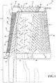
- the core 10 includes an airfoil section 12 and a platform/root section 14.
- the airfoil section 12 of the core 10 comprises a first core element 16 located toward a leading edge 18 and toward a tip 20 of the core 10, and a second core element 22 located toward a trailing edge 24 and at a mid-chord area 26 of the core 10.
- the platform/root section 14 of the core 10 may have any suitable configuration and is provided for forming a platform/root portion P/R P of the airfoil assembly 100.
- the first core element 16 includes a leading edge section 30 (also referred to herein as a first core element leading edge section), a tip section 32 (also referred to herein as a first core element tip section) integral with the leading edge section 30, and a turn section 34 (also referred to herein as a first core element turn section) integral with the leading edge and tip sections 30, 32.
- the turn section 34 is formed at a junction 36 between the leading edge and tip sections 30, 32 and joins the leading edge and tip sections 30, 32.
- the first core element 16 is used to form a leading edge cooling circuit 102 in the airfoil assembly 100.
- the leading edge cooling circuit 102 includes a cooling fluid passage 104 comprising: a leading edge portion 106, which is formed by the first core element leading edge section 30; a tip portion 108 formed by the first core element tip section 32; and a turn portion 110 formed by the first core element turn section 34, wherein the turn portion 110 effects fluid communication between the leading edge and tip portions 106, 108.
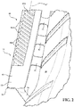
- the leading edge portion 106 of the cooling fluid passage 104 extends in the radial direction R D as shown in Fig. 5 through the airfoil assembly 100 adjacent to the leading edge L E of the airfoil assembly 100.
- the tip portion 108 extends in the chordal direction C D as shown in Fig. 5 from adjacent to the leading edge L E of the airfoil assembly 100 to adjacent to the trailing edge T E of the airfoil assembly 100 near the radially outer end 101B of the airfoil assembly 100.
- the turn portion 110 of the cooling fluid passage 104 is preferably formed by the first core element turn section 34 such that an angle ⁇ between the leading edge portion 106 and the tip portion 108 is within a range of 90 degrees to 130 degrees, see Fig. 5 .
- each of the leading edge portion 106, the tip portion 108, and the turn portion 110 of the cooling fluid passage 104 are formed concurrently in the airfoil assembly 100 by the first core element 16 of the core 10.
- the first core element leading edge section 30 includes first and second radial leading edge elements 38, 40 that form corresponding first and second leading edge passages 130, 132 of the leading edge cooling circuit 102, see Figs. 5-7 .
- the first core element leading edge section 30 further includes a plurality of transition elements 42 extending generally chordally between the first and second radial leading edge elements 38, 40.
- the transition elements 42 form a plurality of transition passages 134 in the airfoil assembly 100, wherein the transition passages 134 provide fluid communication from the first leading edge passage 130 to the second leading edge passage 132.
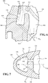
- cooling fluid entering the second leading edge passage 132 from the first leading edge passage 130 through the transition passages 134 impinges on a surface 136 of the airfoil assembly 100 defining an outer boundary of the second leading edge passage 132 to provide impingement cooling of the surface 136, see Fig. 5-7 .
- the transition elements 42 of the core 10 are located further from a first side portion 40A of the second radial leading edge element 40 than to a second side portion 40B of the second radial leading edge element 40, i.e., the transition elements 42 are located closer to the second side portion 40B than to the first side portion 40A of the second radial leading edge element 40, such that the resulting transition passages 134 are located closer to the suction side S S than to the pressure side P S of the airfoil assembly 100.
- the location of the transition passages 134 in this manner promotes a circular or helical flow of cooling fluid through the second leading edge passage 132 during operation.
- transition elements 42 of the core 10 could be formed closer to the first side portion 40A than to the second side portion 40B of the second radial leading edge element 40, wherein the resulting transition passages 134 would be located closer to the pressure side P S than to the suction side S S of the airfoil assembly 100, such that this aspect of the invention is also intended to cover this alternate location of the transition elements 42 and the resulting transition passages 134.
- the core 10 may also comprise an inlet element 50 extending to an inner end 52 of the first core element leading edge section 30, wherein the inner end 52 is opposed from the first core element turning section 34.
- the inlet element 50 is preferably arranged relative to the leading edge section 30 such that a resulting inlet passage 140 formed in the airfoil assembly 100 introduces cooling fluid into the leading edge portion 106, i.e., into the second leading edge passage 132 of the leading edge portion 106, of the cooling passage 104 at an angle ⁇ of, for example, between 25 degrees and 65 degrees relative to a radial axis R A of the leading edge portion 106, see Fig. 6 . Further, as shown in Fig.
- the inlet passage 140 may also be arranged at an angle ⁇ of, for example, about between 25 degrees to 65 degrees relative to the choral direction C D .
- the configuration of the inlet passage 140 in this manner further assists in promoting a circular or helical flow of cooling fluid through the second leading edge passage 132.
- the first core element leading edge section 30, and, more particularly, the second radial leading edge element 40 thereof includes a plurality of helical ridges 56 extending circumferentially and radially with respect to a radial axis R AC of the leading edge section 30, see Fig. 2 .
- the ridges 56 may extend continuously around an outer surface 40A of the second radial leading edge element 40, or may be broken up into individual pieces 56A extending outwardly from the surface 40A as shown in Figs. 2-4 .
- the ridges 56 form corresponding flow directing features, illustrated in Figs.
- helical grooves 146 that extend into a surface 148 of the airfoil assembly 100 defining an outer boundary of the second leading edge passage 132 of the leading edge portion 106 of the cooling passage 104.
- the grooves 146 extend around the surface 148 of the airfoil assembly 100 from an inner end 106A of the leading edge portion 106 to an outer end 106B of the leading edge portion 106, see Fig. 5 .
- the grooves 146 effect a continuous circular or helical flow pattern for cooling fluid flowing radially outwardly through the leading edge portion 106 of the cooling passage 104.
- the turn and tip sections 32, 34 of the core 10 are located toward the outer end of the core 10 to form the tip and turn portions 108, 110 of the airfoil assembly 100 at the outer end 101B thereof.
- the tip section 32 of the core 10 includes outlet structures 60 that form corresponding cooling fluid outlets 150 in the tip portion 108 of the airfoil assembly 100, wherein the cooling fluid outlets 150 are provided for discharging cooling fluid from the airfoil assembly 100 during operation.
- the second core element 22 which is integral with the first core element 16 in accordance with an aspect of the present invention, includes a mid-chord section 66 and a trailing edge section 68. While the mid-chord and trailing edge sections 66, 68 of the second core element 22 could have any suitable shape and configuration, the mid-chord section 66 illustrated in Fig. 1 includes first and second radial mid-chord elements 70, 72 arranged, and the trailing edge section 68 includes airfoil shaped cooling structures 74.
- the mid-chord and trailing edge sections 66, 68 of the second core element 22 are used to form corresponding mid-chord and trailing edge cooling circuits 156, 158 in the airfoil assembly 100 concurrently with the first core element 16 forming each of the components of the leading edge cooling circuit 102, e.g., the first and second leading edge passages 130, 132 of the leading edge portion 106 of the cooling fluid passage 104, and the tip portion 108 and turn portion 110 of the cooling fluid passage 104.
- separate core structures are not required for forming the leading edge, mid-chord, and trailing edge cooling circuits 102, 156, 158 in the airfoil assembly 100.
- the first and second radial mid-chord elements 70, 72 of the second core element 22 form corresponding mid-chord passages 160, 162 of the mid-chord cooling circuit 156, wherein the mid-chord passages 160, 162 extend generally radially through a mid-chord portion M C of the airfoil assembly 100 in a serpentine configuration.
- airfoil shaped cooling passages 164 formed in the trailing edge cooling circuit 158 by the airfoil shaped cooling structures 74 of the core 10.
- the components of the mid-chord, and trailing edge cooling circuits 156, 158 shown in Fig. 5 are exemplary and the invention is not intended to be limited to the configuration of the mid-chord, and trailing edge cooling circuits 156, 158 shown in Fig. 5 .
- small holes 170 may be formed in the airfoil assembly 100 between the tip potion 108 and any or all of the leading edge, mid-chord, and trailing edge cooling circuits 102, 156, 158, see Fig. 5 .
- the holes 170 may be the result of corresponding pedestals 80 (see Fig. 1 ) formed in the core 10, which pedestals 80 provide structural integrity for the core 10. While the holes 170 may provide a small amount of cooling fluid leakage between the tip potion 108 and any or all of the leading edge, mid-chord, and trailing edge cooling circuits 102, 156, 158, it is not believed to be a significant amount of cooling fluid, and it is not believed to significantly affect the cooling performance of cooling fluid flowing through the airfoil assembly 100.
- parts of the core 10 may include conventional cooling enhancement structures, such as turbulating features, e.g., trip strips, bumps, dimples, etc., which form corresponding cooling features in the airfoil assembly to enhance cooling effected by the cooling fluid flowing through the airfoil assembly during operation.
- turbulating features e.g., trip strips, bumps, dimples, etc.
- each of the leading edge portion 106, the tip portion 108, and the turn portion 110 of the cooling fluid passage 104 are formed concurrently in the airfoil assembly 100 by the first core element 16 of the core 10, wherein the mid-chord, and trailing edge cooling circuits 156, 158 are also formed at this time.
- the platform/root portion P/R P of the airfoil assembly 100 may additionally be formed at this time.
- the leading edge portion 106 of the cooling fluid passage 104 of the leading edge cooling circuit 102 of the airfoil assembly 100 receives cooling fluid, such as, for example, compressor discharge air from the platform/root portion P/R P of the airfoil assembly 100, see Fig. 5 .
- cooling fluid such as, for example, compressor discharge air from the platform/root portion P/R P of the airfoil assembly 100, see Fig. 5 .
- the cooling fluid flows radially outward through the first leading edge passage 130 it provides convective cooling to the airfoil assembly 100.
- the inlet and transition passages 140, 134 are preferably formed so as to promote a circular or helical flow of cooling fluid through the second leading edge passage 132, wherein the grooves 146 promote continued circular or helical flow through the second leading edge passage 132.
- the cooling fluid flows radially outward through the second leading edge passage 132 it provides further cooling to the airfoil assembly 100 at the leading edge L E .
- the cooling fluid entering the second leading edge passage 132 from the first leading edge passage 130 through the transition passages 134 impinges on the surface 148 of the airfoil assembly 100 to provide impingement cooling of the surface 148 at the leading edge L E .
- the cooling fluid After flowing radially outwardly through the second leading edge passage 132, the cooling fluid enters the turn portion 110 of the cooling fluid passage 104, wherein the turn portion 110 effects fluid communication between the second leading edge passage 132 and the tip portion 108 of the cooling fluid passage 104. As the cooling fluid flows through the tip portion 108, the cooling fluid provides cooling to the radially outer end 101B of the airfoil assembly 100. The cooling fluid then exits the airfoil assembly 100 via the cooling fluid outlets 150.
- Additional cooling fluid enters the mid-chord and trailing edge cooling circuits 156, 158 of the airfoil assembly 100 from the platform/root portion P/R P , which cooling fluid provides cooling to these areas of the airfoil assembly 100 as will be appreciated by those having ordinary skill in the art.
Landscapes
- Engineering & Computer Science (AREA)
- Mechanical Engineering (AREA)
- General Engineering & Computer Science (AREA)
- Turbine Rotor Nozzle Sealing (AREA)
Claims (14)
- Kernstruktur (10), die zum Ausbilden einer Kühlungsauslegung in einer Gasturbinenmotorschaufel (100) verwendet wird, Folgendes umfassend:
ein erstes Kernelement (16), das einen Vorderkantenabschnitt (30), einen in den Vorderkantenabschnitt (30) integrierten Spitzenabschnitt (32) und einen in den Vorderkanten- und Spitzenabschnitt (30, 32) integrierten und den Vorderkanten- und Spitzenabschnitt (30, 32) verbindenden Wendeabschnitt (34) aufweist, wobei das erste Kernelement (16) dazu eingerichtet ist, dazu verwendet zu werden, einen Vorderkantenkühlkreislauf (102) in einer Gasturbinenmotorschaufel (100) auszubilden, wobei der Vorderkantenkühlkreislauf (102) einen Kühlfluidkanal (104) aufweist, Folgendes umfassend:einen durch den Vorderkantenabschnitt (30) des ersten Kernelements ausgebildeten Vorderkantenbereich (106), wobei sich der Vorderkantenbereich (106) an eine Vorderkante (LE) der Schaufel (100) angrenzend radial durch die Schaufel (100) erstreckt;einen Spitzenbereich (108), der durch den Spitzenabschnitt (32) des ersten Kernelements ausgebildet ist, wobei sich der Spitzenbereich (108) in Sehnenrichtung von der Nähe der Vorderkante (LE) der Schaufel (100) bis in die Nähe der Hinterkante (TE) der Schaufel (100) erstreckt; undeinen durch den Wendeabschnitt (34) des ersten Kernelements ausgebildeten Wendebereich (110), wobei der Wendebereich (110) eine Fluidverbindung zwischen dem Vorderkantenbereich (106) und dem Spitzenbereich (108) des Kühlungskanals (104) ermöglicht;wobei der Vorderkantenbereich (106), der Spitzenbereich (108) und der Wendebereich (110) des Kühlfluidkanals (104) dazu eingerichtet sind, durch das erste Kernelement (16) gleichzeitig in der Schaufel (100) ausgebildet zu werden,dadurch gekennzeichnet, dass der Vorderkantenabschnitt (30) des ersten Kernelements (16) mehrere wendelförmige Rippen (56) aufweist, die sich in Umfangsrichtung und radial in Bezug zu einer Radialachse (RAC) des Vorderkantenabschnitts (30) erstrecken, wobei die Rippen (56) zugehörige wendelförmige Nuten (146) ausbilden, die sich in eine Fläche (148) der Schaufel (100) erstrecken, die eine Außenbegrenzung des Vorderkantenbereichs (106) des Kühlungskanals (104) definiert,wobei die Nuten (146) ein wendelförmiges Strömungsmuster für Kühlfluid bewirken, das durch den Vorderkantenbereich (106) des Kühlungskanals (104) radial nach außen strömt. - Kernstruktur (10) nach Anspruch 1, wobei der Wendeabschnitt (34) des ersten Kernelements (16) den Wendebereich (110) des Kühlfluidkanals (104) derart ausbildet, dass ein Winkel zwischen dem Vorderkantenbereich (106) und dem Spitzenbereich (108) innerhalb eines Bereichs von 90 bis 130 Grad liegt.
- Kernstruktur (10) nach Anspruch 1, ferner ein in das erste Kernelement (16) integriertes zweites Kernelement (22) umfassend, wobei das zweite Kernelement (22) einen Mittelsehnenabschnitt (66) aufweist, der dazu verwendet wird, gleichzeitig mit dem Ausbilden des Vorderkantenkühlkreislaufs (102) durch das erste Kernelement (16) einen Mittelsehnenkühlkreislauf (156) in der Schaufel (100) auszubilden.
- Kernstruktur (10) nach Anspruch 3, wobei der Mittelsehnenabschnitt (66) mindestens zwei radiale Mittelsehnenelemente (70, 72) aufweist, die zugehörige Mittelsehnenkanäle (160, 162) des Mittelsehnenkühlkreislaufs (156) ausbilden, wobei sich die Mittelsehnenkanäle (160, 162) im Allgemeinen radial durch einen Mittelsehnenbereich (MC) der Schaufel (100) erstrecken.
- Kernstruktur (10) nach Anspruch 3, wobei das zweite Kernelement (22) ferner einen in den Mittelsehnenabschnitt (66) integrierten Hinterkantenabschnitt (68) aufweist, wobei der Hinterkantenabschnitts (68) dazu verwendet wird, gleichzeitig mit dem Ausbilden des Mittelsehnenkühlkreislaufs (156) durch den Mittelsehnenabschnitt (66) einen Hinterkantenkühlkreislauf (158) in der Schaufel (100) auszubilden.
- Kernstruktur (10) nach Anspruch 1, wobei der Vorderkantenabschnitt (30) des ersten Kernelements (16) ein erstes und zweites radiales Vorderkantenelement (38, 40) aufweist, die einen zugehörigen ersten und zweiten Vorderkantenkanal (130, 132) des Vorderkantenkühlkreises (102) ausbilden.
- Kernstruktur (10) nach Anspruch 6, ferner mehrere Übergangselements (42) umfassend, die sich zwischen dem ersten und zweiten radialen Vorderkantenelement (38, 40) erstrecken, wobei die Übergangselemente (42) dazu verwendet werden, mehrere Übergangskanäle (134) in der Schaufel (100) auszubilden, die eine Fluidverbindung vom ersten Vorderkantenkanal (130) zum zweiten Vorderkantenkanal (132) vorsehen, wobei vom ersten Vorderkantenkanal (130) durch die Übergangskanäle (134) in den zweiten Vorderkantenkanal (132) eintretendes Kühlfluid auf einer Fläche (136) der Schaufel (100), die eine Außenbegrenzung des zweiten Vorderkantenkanals (132) definiert, aufprallt, um eine Prallkühlung der Fläche (136) vorzusehen.
- Kernstruktur (10) nach Anspruch 7, wobei sich die Übergangselemente (42) näher an einem ersten Seitenbereich (40B) oder einem zweiten Seitenbereich (40A) des zweiten radialen Vorderkantenelements (40) befinden, sodass sich die Übergangskanäle (134) näher an der Druck- oder Saugseite (PS, SS) der Schaufel (100) befinden als an der anderen Seite.
- Kernstruktur (10) nach Anspruch 1, ferner ein Einlasselement (50) umfassend, das sich zu einem dem Wendeabschnitt (34) entgegengesetzten Ende (52) des Vorderkantenabschnitts (30) des ersten Kernelements (16) erstreckt, wobei das Einlasselement (50) in Bezug zum Vorderkantenabschnitt (30) derart angeordnet ist, dass ein in der sich ergebenden Schaufel (100) ausgebildeter Einlasskanal (140) Kühlfluid in einem Winkel von zwischen 25 Grad und 65 Grad in Bezug zu einer Radialachse (RA) des Vorderkantenbereichs (106) in den Vorderkantenbereich (106) des Kühlungskanals (104) einleitet.
- Schaufel (100) für einen Gasturbinenmotor, Folgendes umfassend:eine Außenwand (101), die eine Vorderkante (LE), eine Hinterkante (TE), eine Druckseite (PS), eine Saugseite (SS), ein radial inneres Ende (010A) und ein radial äußeres Ende (101B) aufweist, wobei eine Sehnenrichtung (CD) zwischen der Vorder- und Hinterkante (LE, TE) definiert ist;einen in der Außenwand (101) definierten Vorderkantenkühlkreislauf (102), wobei der Vorderkantenkühlkreislauf (102) Kühlfluid zum Kühlen der Außenwand (101) aufnimmt und Folgendes umfasst:einen Kühlfluidkanal (104), der Folgendes aufweist:einen Vorderkantenbereich (106), der sich an die Vorderkante (LE) angrenzend radial durch die Schaufel (100) erstreckt;einen Spitzenbereich (108), der sich in Sehnenrichtung von der Nähe der Vorderkante (LE) bis in die Nähe der Hinterkante (TE) erstreckt; undeinen Wendebereich (110), der die Fluidverbindung zwischen dem Vorderkantenbereich (106) und dem Spitzenbereich (108) ermöglicht;dadurch gekennzeichnet, dass der Vorderkantenbereich (106) des Kühlfluidkanals (104) mehrere wendelförmige Nuten(146)-Merkmalen aufweist, die ein wendelförmiges Strömungsmuster für Kühlfluid bewirken, das durch den Vorderkantenbereich (104) radial nach außen strömt.
- Schaufel (100) nach Anspruch 10, wobei jeder Bereich (106, 108, 110) des Kühlungskanals (104) unter Verwendung eines ersten Kernelements (16) einer Kernstruktur (10) gleichzeitig mit den anderen Bereichen (106, 108, 110) ausgebildet wird.
- Schaufel (100) nach Anspruch 11, ferner Folgendes umfassend:einen durch einen Mittelsehnenabschnitt (66) der Kernstruktur (10) in das erste Kernelement (16) integriert ausgebildeten Mittelsehnenkühlkreislauf (156), wobei der Mittelsehnenkühlkreislauf (156) gleichzeitig mit dem Ausbilden des Vorderkantenkühlkreislaufs (102) durch das erste Kernelement (16) ausgebildet wird; undeinen durch einen Hinterkantenabschnitt (68) der Kernstruktur (10) in den Mittelsehnenabschnitt (66) integriert ausgebildeten Hinterkantenkühlkreislauf (158), wobei der Hinterkantenkühlkreislauf (158) gleichzeitig mit dem Ausbilden des Vorderkantenkühlkreislaufs (102) durch die Kernstruktur (10) ausgebildet wird.
- Schaufel (100) nach Anspruch 10, wobei der Vorderkantenbereich (106) des Kühlfluidkanals (104) einen ersten und zweiten Vorderkantenkanal (130, 132) aufweist, die sich im Allgemeinen radial durch die Schaufel (100) erstrecken.
- Schaufel (100) nach Anspruch 13, ferner mehrere Übergangskanäle (134) umfassend, die eine Fluidverbindung vom ersten Vorderkantenkanal (130) zum zweiten Vorderkantenkanal (132) vorsehen, wobei vom ersten Vorderkantenkanal (130) durch die Übergangskanäle (134) in den zweiten Vorderkantenkanal (132) eintretendes Kühlfluid auf einer Fläche (136) der Schaufel (100) aufprallt, die eine Außenbegrenzung des ersten Vorderkantenkanals (130) definiert, um eine Prallkühlung der Fläche (136) vorzusehen.
Applications Claiming Priority (1)
| Application Number | Priority Date | Filing Date | Title |
|---|---|---|---|
| PCT/US2014/056188 WO2016043742A1 (en) | 2014-09-18 | 2014-09-18 | Gas turbine airfoil including integrated leading edge and tip cooling fluid passage and core structure used for forming such an airfoil |
Publications (2)
| Publication Number | Publication Date |
|---|---|
| EP3194726A1 EP3194726A1 (de) | 2017-07-26 |
| EP3194726B1 true EP3194726B1 (de) | 2020-04-15 |
Family
ID=51628486
Family Applications (1)
| Application Number | Title | Priority Date | Filing Date |
|---|---|---|---|
| EP14777462.4A Active EP3194726B1 (de) | 2014-09-18 | 2014-09-18 | Gasturbinenschaufel mit integriertem flüssigkeitskanal für eintrittskanten- und spitzenkühlung und kernstruktur zur herstellung einer derartigen schaufel |
Country Status (5)
| Country | Link |
|---|---|
| US (1) | US10697306B2 (de) |
| EP (1) | EP3194726B1 (de) |
| JP (1) | JP2017534791A (de) |
| CN (1) | CN106715834B (de) |
| WO (1) | WO2016043742A1 (de) |
Families Citing this family (5)
| Publication number | Priority date | Publication date | Assignee | Title |
|---|---|---|---|---|
| US10119404B2 (en) | 2014-10-15 | 2018-11-06 | Honeywell International Inc. | Gas turbine engines with improved leading edge airfoil cooling |
| US20190003316A1 (en) * | 2017-06-29 | 2019-01-03 | United Technologies Corporation | Helical skin cooling passages for turbine airfoils |
| KR102181265B1 (ko) * | 2019-02-26 | 2020-12-02 | 두산중공업 주식회사 | 터빈 베인, 터빈 블레이드 및 이를 포함하는 가스 터빈 |
| EP3832069A1 (de) * | 2019-12-06 | 2021-06-09 | Siemens Aktiengesellschaft | Turbinenschaufel für eine stationäre gasturbine |
| JP2023165485A (ja) * | 2022-05-06 | 2023-11-16 | 三菱重工業株式会社 | タービン翼及びガスタービン |
Family Cites Families (30)
| Publication number | Priority date | Publication date | Assignee | Title |
|---|---|---|---|---|
| US5002460A (en) * | 1989-10-02 | 1991-03-26 | General Electric Company | Internally cooled airfoil blade |
| US5704763A (en) | 1990-08-01 | 1998-01-06 | General Electric Company | Shear jet cooling passages for internally cooled machine elements |
| US5340274A (en) * | 1991-11-19 | 1994-08-23 | General Electric Company | Integrated steam/air cooling system for gas turbines |
| US5599166A (en) | 1994-11-01 | 1997-02-04 | United Technologies Corporation | Core for fabrication of gas turbine engine airfoils |
| US5820774A (en) | 1996-10-28 | 1998-10-13 | United Technologies Corporation | Ceramic core for casting a turbine blade |
| US6331098B1 (en) | 1999-12-18 | 2001-12-18 | General Electric Company | Coriolis turbulator blade |
| US6390774B1 (en) | 2000-02-02 | 2002-05-21 | General Electric Company | Gas turbine bucket cooling circuit and related process |
| US6431832B1 (en) * | 2000-10-12 | 2002-08-13 | Solar Turbines Incorporated | Gas turbine engine airfoils with improved cooling |
| GB0025012D0 (en) | 2000-10-12 | 2000-11-29 | Rolls Royce Plc | Cooling of gas turbine engine aerofoils |
| GB2395232B (en) * | 2002-11-12 | 2006-01-25 | Rolls Royce Plc | Turbine components |
| US6761535B1 (en) | 2003-04-28 | 2004-07-13 | General Electric Company | Internal core profile for a turbine bucket |
| US7004720B2 (en) | 2003-12-17 | 2006-02-28 | Pratt & Whitney Canada Corp. | Cooled turbine vane platform |
| US6966756B2 (en) | 2004-01-09 | 2005-11-22 | General Electric Company | Turbine bucket cooling passages and internal core for producing the passages |
| EP1621730B1 (de) | 2004-07-26 | 2008-10-08 | Siemens Aktiengesellschaft | Gekühltes Bauteil einer Strömungsmaschine und Verfahren zum Giessen dieses gekühlten Bauteils |
| US7249933B2 (en) | 2005-01-10 | 2007-07-31 | General Electric Company | Funnel fillet turbine stage |
| US7690894B1 (en) | 2006-09-25 | 2010-04-06 | Florida Turbine Technologies, Inc. | Ceramic core assembly for serpentine flow circuit in a turbine blade |
| US7674093B2 (en) | 2006-12-19 | 2010-03-09 | General Electric Company | Cluster bridged casting core |
| US20080264035A1 (en) * | 2007-04-25 | 2008-10-30 | Ricciardo Mark J | Coolant flow swirler for a rocket engine |
| US8201621B2 (en) * | 2008-12-08 | 2012-06-19 | General Electric Company | Heat exchanging hollow passages with helicoidal grooves |
| US8192146B2 (en) | 2009-03-04 | 2012-06-05 | Siemens Energy, Inc. | Turbine blade dual channel cooling system |
| US20100239409A1 (en) * | 2009-03-18 | 2010-09-23 | General Electric Company | Method of Using and Reconstructing a Film-Cooling Augmentation Device for a Turbine Airfoil |
| US9630277B2 (en) | 2010-03-15 | 2017-04-25 | Siemens Energy, Inc. | Airfoil having built-up surface with embedded cooling passage |
| US8371815B2 (en) * | 2010-03-17 | 2013-02-12 | General Electric Company | Apparatus for cooling an airfoil |
| US9011077B2 (en) | 2011-04-20 | 2015-04-21 | Siemens Energy, Inc. | Cooled airfoil in a turbine engine |
| US8347945B1 (en) | 2011-07-29 | 2013-01-08 | United Technologies Corporation | Platform interconnected with mid-body core interface for molding airfoil platforms |
| US8905714B2 (en) | 2011-12-30 | 2014-12-09 | General Electric Company | Turbine rotor blade platform cooling |
| US20130280093A1 (en) | 2012-04-24 | 2013-10-24 | Mark F. Zelesky | Gas turbine engine core providing exterior airfoil portion |
| US9765630B2 (en) * | 2013-01-09 | 2017-09-19 | General Electric Company | Interior cooling circuits in turbine blades |
| US20150204197A1 (en) * | 2014-01-23 | 2015-07-23 | Siemens Aktiengesellschaft | Airfoil leading edge chamber cooling with angled impingement |
| US20170101870A1 (en) * | 2015-10-12 | 2017-04-13 | United Technologies Corporation | Cooling holes of turbine |
-
2014
- 2014-09-18 WO PCT/US2014/056188 patent/WO2016043742A1/en active Application Filing
- 2014-09-18 US US15/508,497 patent/US10697306B2/en active Active
- 2014-09-18 EP EP14777462.4A patent/EP3194726B1/de active Active
- 2014-09-18 JP JP2017515126A patent/JP2017534791A/ja active Pending
- 2014-09-18 CN CN201480082009.XA patent/CN106715834B/zh not_active Expired - Fee Related
Non-Patent Citations (1)
| Title |
|---|
| None * |
Also Published As
| Publication number | Publication date |
|---|---|
| CN106715834B (zh) | 2019-01-08 |
| JP2017534791A (ja) | 2017-11-24 |
| US20170275998A1 (en) | 2017-09-28 |
| WO2016043742A1 (en) | 2016-03-24 |
| CN106715834A (zh) | 2017-05-24 |
| EP3194726A1 (de) | 2017-07-26 |
| US10697306B2 (en) | 2020-06-30 |
Similar Documents
| Publication | Publication Date | Title |
|---|---|---|
| US8840363B2 (en) | Trailing edge cooling system in a turbine airfoil assembly | |
| EP1918522B1 (de) | Bauteil für ein Gasturbinentriebwerk | |
| US8985949B2 (en) | Cooling system including wavy cooling chamber in a trailing edge portion of an airfoil assembly | |
| US10393022B2 (en) | Cooled component having effusion cooling apertures | |
| US9011077B2 (en) | Cooled airfoil in a turbine engine | |
| JP6434145B2 (ja) | 軸方向先端冷却回路を備えたタービンブレード | |
| EP1959097B1 (de) | Prallkühlung für Verkleidung und Innenteil einer Gasturbinenmotorschaufel | |
| EP3194726B1 (de) | Gasturbinenschaufel mit integriertem flüssigkeitskanal für eintrittskanten- und spitzenkühlung und kernstruktur zur herstellung einer derartigen schaufel | |
| JP6824623B2 (ja) | フレア状先端を有するロータブレード | |
| EP3156597B1 (de) | Kühllöcher einer turbine | |
| EP3088675A1 (de) | Laufschaufel mit aufgeweiteter spitze und zugehörige gasturbine | |
| US9938835B2 (en) | Method and systems for providing cooling for a turbine assembly | |
| US8668454B2 (en) | Turbine airfoil fillet cooling system | |
| US10648342B2 (en) | Engine component with cooling hole | |
| US10605170B2 (en) | Engine component with film cooling | |
| US9745853B2 (en) | Integrated circuit cooled turbine blade | |
| US8118554B1 (en) | Turbine vane with endwall cooling | |
| JP2017534791A5 (de) | ||
| US8882448B2 (en) | Cooling system in a turbine airfoil assembly including zigzag cooling passages interconnected with radial passageways | |
| WO2017003455A1 (en) | Turbine stator vane cooling circuit with flow stream separation | |
| WO2017082907A1 (en) | Turbine airfoil with a cooled trailing edge | |
| EP2378071A1 (de) | Turbineneinheit mit Kühlanordnung und Kühlverfahren |
Legal Events
| Date | Code | Title | Description |
|---|---|---|---|
| STAA | Information on the status of an ep patent application or granted ep patent |
Free format text: STATUS: THE INTERNATIONAL PUBLICATION HAS BEEN MADE |
|
| PUAI | Public reference made under article 153(3) epc to a published international application that has entered the european phase |
Free format text: ORIGINAL CODE: 0009012 |
|
| STAA | Information on the status of an ep patent application or granted ep patent |
Free format text: STATUS: REQUEST FOR EXAMINATION WAS MADE |
|
| 17P | Request for examination filed |
Effective date: 20170223 |
|
| AK | Designated contracting states |
Kind code of ref document: A1 Designated state(s): AL AT BE BG CH CY CZ DE DK EE ES FI FR GB GR HR HU IE IS IT LI LT LU LV MC MK MT NL NO PL PT RO RS SE SI SK SM TR |
|
| AX | Request for extension of the european patent |
Extension state: BA ME |
|
| RIN1 | Information on inventor provided before grant (corrected) |
Inventor name: PU, ZHENGXIANG Inventor name: LEE, CHING-PANG Inventor name: HILLIER, GERALD L. Inventor name: SCHROEDER, ERIC Inventor name: JOHNSON, ERIK Inventor name: MCDONALD, WAYNE J. Inventor name: UM, JAE Y. Inventor name: WAYWOOD, ANTHONY |
|
| RAP1 | Party data changed (applicant data changed or rights of an application transferred) |
Owner name: SIEMENS AKTIENGESELLSCHAFT |
|
| DAX | Request for extension of the european patent (deleted) | ||
| STAA | Information on the status of an ep patent application or granted ep patent |
Free format text: STATUS: EXAMINATION IS IN PROGRESS |
|
| 17Q | First examination report despatched |
Effective date: 20190205 |
|
| GRAP | Despatch of communication of intention to grant a patent |
Free format text: ORIGINAL CODE: EPIDOSNIGR1 |
|
| STAA | Information on the status of an ep patent application or granted ep patent |
Free format text: STATUS: GRANT OF PATENT IS INTENDED |
|
| INTG | Intention to grant announced |
Effective date: 20191128 |
|
| RIN1 | Information on inventor provided before grant (corrected) |
Inventor name: SCHROEDER, ERIC Inventor name: HILLIER, GERALD L. Inventor name: LEE, CHING-PANG Inventor name: JOHNSON, ERIK Inventor name: PU, ZHENGXIANG Inventor name: WAYWOOD, ANTHONY Inventor name: MCDONALD, WAYNE J. Inventor name: UM, JAE Y. |
|
| GRAS | Grant fee paid |
Free format text: ORIGINAL CODE: EPIDOSNIGR3 |
|
| GRAA | (expected) grant |
Free format text: ORIGINAL CODE: 0009210 |
|
| STAA | Information on the status of an ep patent application or granted ep patent |
Free format text: STATUS: THE PATENT HAS BEEN GRANTED |
|
| AK | Designated contracting states |
Kind code of ref document: B1 Designated state(s): AL AT BE BG CH CY CZ DE DK EE ES FI FR GB GR HR HU IE IS IT LI LT LU LV MC MK MT NL NO PL PT RO RS SE SI SK SM TR |
|
| REG | Reference to a national code |
Ref country code: CH Ref legal event code: EP |
|
| REG | Reference to a national code |
Ref country code: DE Ref legal event code: R096 Ref document number: 602014063824 Country of ref document: DE |
|
| REG | Reference to a national code |
Ref country code: IE Ref legal event code: FG4D |
|
| REG | Reference to a national code |
Ref country code: AT Ref legal event code: REF Ref document number: 1257512 Country of ref document: AT Kind code of ref document: T Effective date: 20200515 |
|
| REG | Reference to a national code |
Ref country code: CH Ref legal event code: NV Representative=s name: SIEMENS SCHWEIZ AG, CH |
|
| REG | Reference to a national code |
Ref country code: NL Ref legal event code: MP Effective date: 20200415 |
|
| REG | Reference to a national code |
Ref country code: LT Ref legal event code: MG4D |
|
| PG25 | Lapsed in a contracting state [announced via postgrant information from national office to epo] |
Ref country code: NO Free format text: LAPSE BECAUSE OF FAILURE TO SUBMIT A TRANSLATION OF THE DESCRIPTION OR TO PAY THE FEE WITHIN THE PRESCRIBED TIME-LIMIT Effective date: 20200715 Ref country code: GR Free format text: LAPSE BECAUSE OF FAILURE TO SUBMIT A TRANSLATION OF THE DESCRIPTION OR TO PAY THE FEE WITHIN THE PRESCRIBED TIME-LIMIT Effective date: 20200716 Ref country code: FI Free format text: LAPSE BECAUSE OF FAILURE TO SUBMIT A TRANSLATION OF THE DESCRIPTION OR TO PAY THE FEE WITHIN THE PRESCRIBED TIME-LIMIT Effective date: 20200415 Ref country code: LT Free format text: LAPSE BECAUSE OF FAILURE TO SUBMIT A TRANSLATION OF THE DESCRIPTION OR TO PAY THE FEE WITHIN THE PRESCRIBED TIME-LIMIT Effective date: 20200415 Ref country code: IS Free format text: LAPSE BECAUSE OF FAILURE TO SUBMIT A TRANSLATION OF THE DESCRIPTION OR TO PAY THE FEE WITHIN THE PRESCRIBED TIME-LIMIT Effective date: 20200815 Ref country code: SE Free format text: LAPSE BECAUSE OF FAILURE TO SUBMIT A TRANSLATION OF THE DESCRIPTION OR TO PAY THE FEE WITHIN THE PRESCRIBED TIME-LIMIT Effective date: 20200415 Ref country code: NL Free format text: LAPSE BECAUSE OF FAILURE TO SUBMIT A TRANSLATION OF THE DESCRIPTION OR TO PAY THE FEE WITHIN THE PRESCRIBED TIME-LIMIT Effective date: 20200415 Ref country code: PT Free format text: LAPSE BECAUSE OF FAILURE TO SUBMIT A TRANSLATION OF THE DESCRIPTION OR TO PAY THE FEE WITHIN THE PRESCRIBED TIME-LIMIT Effective date: 20200817 |
|
| REG | Reference to a national code |
Ref country code: AT Ref legal event code: MK05 Ref document number: 1257512 Country of ref document: AT Kind code of ref document: T Effective date: 20200415 |
|
| PG25 | Lapsed in a contracting state [announced via postgrant information from national office to epo] |
Ref country code: RS Free format text: LAPSE BECAUSE OF FAILURE TO SUBMIT A TRANSLATION OF THE DESCRIPTION OR TO PAY THE FEE WITHIN THE PRESCRIBED TIME-LIMIT Effective date: 20200415 Ref country code: BG Free format text: LAPSE BECAUSE OF FAILURE TO SUBMIT A TRANSLATION OF THE DESCRIPTION OR TO PAY THE FEE WITHIN THE PRESCRIBED TIME-LIMIT Effective date: 20200715 Ref country code: LV Free format text: LAPSE BECAUSE OF FAILURE TO SUBMIT A TRANSLATION OF THE DESCRIPTION OR TO PAY THE FEE WITHIN THE PRESCRIBED TIME-LIMIT Effective date: 20200415 Ref country code: HR Free format text: LAPSE BECAUSE OF FAILURE TO SUBMIT A TRANSLATION OF THE DESCRIPTION OR TO PAY THE FEE WITHIN THE PRESCRIBED TIME-LIMIT Effective date: 20200415 |
|
| REG | Reference to a national code |
Ref country code: DE Ref legal event code: R081 Ref document number: 602014063824 Country of ref document: DE Owner name: SIEMENS ENERGY GLOBAL GMBH & CO. KG, DE Free format text: FORMER OWNER: SIEMENS AKTIENGESELLSCHAFT, 80333 MUENCHEN, DE |
|
| PG25 | Lapsed in a contracting state [announced via postgrant information from national office to epo] |
Ref country code: AL Free format text: LAPSE BECAUSE OF FAILURE TO SUBMIT A TRANSLATION OF THE DESCRIPTION OR TO PAY THE FEE WITHIN THE PRESCRIBED TIME-LIMIT Effective date: 20200415 |
|
| REG | Reference to a national code |
Ref country code: DE Ref legal event code: R097 Ref document number: 602014063824 Country of ref document: DE |
|
| RAP2 | Party data changed (patent owner data changed or rights of a patent transferred) |
Owner name: SIEMENS ENERGY GLOBAL GMBH & CO. KG |
|
| PG25 | Lapsed in a contracting state [announced via postgrant information from national office to epo] |
Ref country code: ES Free format text: LAPSE BECAUSE OF FAILURE TO SUBMIT A TRANSLATION OF THE DESCRIPTION OR TO PAY THE FEE WITHIN THE PRESCRIBED TIME-LIMIT Effective date: 20200415 Ref country code: DK Free format text: LAPSE BECAUSE OF FAILURE TO SUBMIT A TRANSLATION OF THE DESCRIPTION OR TO PAY THE FEE WITHIN THE PRESCRIBED TIME-LIMIT Effective date: 20200415 Ref country code: SM Free format text: LAPSE BECAUSE OF FAILURE TO SUBMIT A TRANSLATION OF THE DESCRIPTION OR TO PAY THE FEE WITHIN THE PRESCRIBED TIME-LIMIT Effective date: 20200415 Ref country code: CZ Free format text: LAPSE BECAUSE OF FAILURE TO SUBMIT A TRANSLATION OF THE DESCRIPTION OR TO PAY THE FEE WITHIN THE PRESCRIBED TIME-LIMIT Effective date: 20200415 Ref country code: AT Free format text: LAPSE BECAUSE OF FAILURE TO SUBMIT A TRANSLATION OF THE DESCRIPTION OR TO PAY THE FEE WITHIN THE PRESCRIBED TIME-LIMIT Effective date: 20200415 Ref country code: EE Free format text: LAPSE BECAUSE OF FAILURE TO SUBMIT A TRANSLATION OF THE DESCRIPTION OR TO PAY THE FEE WITHIN THE PRESCRIBED TIME-LIMIT Effective date: 20200415 Ref country code: RO Free format text: LAPSE BECAUSE OF FAILURE TO SUBMIT A TRANSLATION OF THE DESCRIPTION OR TO PAY THE FEE WITHIN THE PRESCRIBED TIME-LIMIT Effective date: 20200415 |
|
| PLBE | No opposition filed within time limit |
Free format text: ORIGINAL CODE: 0009261 |
|
| STAA | Information on the status of an ep patent application or granted ep patent |
Free format text: STATUS: NO OPPOSITION FILED WITHIN TIME LIMIT |
|
| PG25 | Lapsed in a contracting state [announced via postgrant information from national office to epo] |
Ref country code: PL Free format text: LAPSE BECAUSE OF FAILURE TO SUBMIT A TRANSLATION OF THE DESCRIPTION OR TO PAY THE FEE WITHIN THE PRESCRIBED TIME-LIMIT Effective date: 20200415 Ref country code: SK Free format text: LAPSE BECAUSE OF FAILURE TO SUBMIT A TRANSLATION OF THE DESCRIPTION OR TO PAY THE FEE WITHIN THE PRESCRIBED TIME-LIMIT Effective date: 20200415 |
|
| 26N | No opposition filed |
Effective date: 20210118 |
|
| PG25 | Lapsed in a contracting state [announced via postgrant information from national office to epo] |
Ref country code: MC Free format text: LAPSE BECAUSE OF FAILURE TO SUBMIT A TRANSLATION OF THE DESCRIPTION OR TO PAY THE FEE WITHIN THE PRESCRIBED TIME-LIMIT Effective date: 20200415 |
|
| PG25 | Lapsed in a contracting state [announced via postgrant information from national office to epo] |
Ref country code: SI Free format text: LAPSE BECAUSE OF FAILURE TO SUBMIT A TRANSLATION OF THE DESCRIPTION OR TO PAY THE FEE WITHIN THE PRESCRIBED TIME-LIMIT Effective date: 20200415 |
|
| REG | Reference to a national code |
Ref country code: BE Ref legal event code: MM Effective date: 20200930 |
|
| PG25 | Lapsed in a contracting state [announced via postgrant information from national office to epo] |
Ref country code: LU Free format text: LAPSE BECAUSE OF NON-PAYMENT OF DUE FEES Effective date: 20200918 |
|
| PG25 | Lapsed in a contracting state [announced via postgrant information from national office to epo] |
Ref country code: IE Free format text: LAPSE BECAUSE OF NON-PAYMENT OF DUE FEES Effective date: 20200918 Ref country code: BE Free format text: LAPSE BECAUSE OF NON-PAYMENT OF DUE FEES Effective date: 20200930 |
|
| PGFP | Annual fee paid to national office [announced via postgrant information from national office to epo] |
Ref country code: IT Payment date: 20210920 Year of fee payment: 8 Ref country code: FR Payment date: 20210920 Year of fee payment: 8 |
|
| REG | Reference to a national code |
Ref country code: GB Ref legal event code: 732E Free format text: REGISTERED BETWEEN 20211202 AND 20211209 |
|
| PGFP | Annual fee paid to national office [announced via postgrant information from national office to epo] |
Ref country code: DE Payment date: 20211125 Year of fee payment: 8 Ref country code: GB Payment date: 20211029 Year of fee payment: 8 |
|
| PGFP | Annual fee paid to national office [announced via postgrant information from national office to epo] |
Ref country code: CH Payment date: 20211208 Year of fee payment: 8 |
|
| PG25 | Lapsed in a contracting state [announced via postgrant information from national office to epo] |
Ref country code: TR Free format text: LAPSE BECAUSE OF FAILURE TO SUBMIT A TRANSLATION OF THE DESCRIPTION OR TO PAY THE FEE WITHIN THE PRESCRIBED TIME-LIMIT Effective date: 20200415 Ref country code: MT Free format text: LAPSE BECAUSE OF FAILURE TO SUBMIT A TRANSLATION OF THE DESCRIPTION OR TO PAY THE FEE WITHIN THE PRESCRIBED TIME-LIMIT Effective date: 20200415 Ref country code: CY Free format text: LAPSE BECAUSE OF FAILURE TO SUBMIT A TRANSLATION OF THE DESCRIPTION OR TO PAY THE FEE WITHIN THE PRESCRIBED TIME-LIMIT Effective date: 20200415 |
|
| PG25 | Lapsed in a contracting state [announced via postgrant information from national office to epo] |
Ref country code: MK Free format text: LAPSE BECAUSE OF FAILURE TO SUBMIT A TRANSLATION OF THE DESCRIPTION OR TO PAY THE FEE WITHIN THE PRESCRIBED TIME-LIMIT Effective date: 20200415 |
|
| REG | Reference to a national code |
Ref country code: DE Ref legal event code: R119 Ref document number: 602014063824 Country of ref document: DE |
|
| REG | Reference to a national code |
Ref country code: CH Ref legal event code: PL |
|
| GBPC | Gb: european patent ceased through non-payment of renewal fee |
Effective date: 20220918 |
|
| PG25 | Lapsed in a contracting state [announced via postgrant information from national office to epo] |
Ref country code: LI Free format text: LAPSE BECAUSE OF NON-PAYMENT OF DUE FEES Effective date: 20220930 Ref country code: FR Free format text: LAPSE BECAUSE OF NON-PAYMENT OF DUE FEES Effective date: 20220930 Ref country code: DE Free format text: LAPSE BECAUSE OF NON-PAYMENT OF DUE FEES Effective date: 20230401 Ref country code: CH Free format text: LAPSE BECAUSE OF NON-PAYMENT OF DUE FEES Effective date: 20220930 |
|
| PG25 | Lapsed in a contracting state [announced via postgrant information from national office to epo] |
Ref country code: IT Free format text: LAPSE BECAUSE OF NON-PAYMENT OF DUE FEES Effective date: 20220918 Ref country code: GB Free format text: LAPSE BECAUSE OF NON-PAYMENT OF DUE FEES Effective date: 20220918 |