EP3194143B1 - Method of heating a thermoplastic object and apparatus therefore - Google Patents
Method of heating a thermoplastic object and apparatus therefore Download PDFInfo
- Publication number
- EP3194143B1 EP3194143B1 EP15778364.8A EP15778364A EP3194143B1 EP 3194143 B1 EP3194143 B1 EP 3194143B1 EP 15778364 A EP15778364 A EP 15778364A EP 3194143 B1 EP3194143 B1 EP 3194143B1
- Authority
- EP
- European Patent Office
- Prior art keywords
- preform
- thermal energy
- conduction
- radiation
- shaping
- Prior art date
- Legal status (The legal status is an assumption and is not a legal conclusion. Google has not performed a legal analysis and makes no representation as to the accuracy of the status listed.)
- Active
Links
- 238000010438 heat treatment Methods 0.000 title claims description 37
- 238000000034 method Methods 0.000 title claims description 13
- 229920001169 thermoplastic Polymers 0.000 title claims description 11
- 239000004416 thermosoftening plastic Substances 0.000 title claims description 7
- 230000005855 radiation Effects 0.000 claims description 20
- 238000009434 installation Methods 0.000 claims description 19
- 239000012815 thermoplastic material Substances 0.000 claims description 15
- 239000002131 composite material Substances 0.000 claims description 14
- 239000012530 fluid Substances 0.000 claims description 14
- 238000007493 shaping process Methods 0.000 claims description 12
- 238000011144 upstream manufacturing Methods 0.000 claims description 4
- 238000000605 extraction Methods 0.000 claims 2
- 239000000463 material Substances 0.000 description 21
- 239000003570 air Substances 0.000 description 15
- 230000003647 oxidation Effects 0.000 description 8
- 238000007254 oxidation reaction Methods 0.000 description 8
- 238000002844 melting Methods 0.000 description 7
- 230000008018 melting Effects 0.000 description 7
- 238000004519 manufacturing process Methods 0.000 description 4
- 229920002647 polyamide Polymers 0.000 description 4
- 239000004753 textile Substances 0.000 description 4
- 239000004952 Polyamide Substances 0.000 description 3
- 230000000593 degrading effect Effects 0.000 description 3
- 238000002347 injection Methods 0.000 description 3
- 239000007924 injection Substances 0.000 description 3
- 239000010410 layer Substances 0.000 description 3
- 239000002861 polymer material Substances 0.000 description 3
- IJGRMHOSHXDMSA-UHFFFAOYSA-N Atomic nitrogen Chemical compound N#N IJGRMHOSHXDMSA-UHFFFAOYSA-N 0.000 description 2
- QVGXLLKOCUKJST-UHFFFAOYSA-N atomic oxygen Chemical compound [O] QVGXLLKOCUKJST-UHFFFAOYSA-N 0.000 description 2
- 239000011159 matrix material Substances 0.000 description 2
- 239000001301 oxygen Substances 0.000 description 2
- 229910052760 oxygen Inorganic materials 0.000 description 2
- 239000002344 surface layer Substances 0.000 description 2
- 238000003856 thermoforming Methods 0.000 description 2
- OKTJSMMVPCPJKN-UHFFFAOYSA-N Carbon Chemical compound [C] OKTJSMMVPCPJKN-UHFFFAOYSA-N 0.000 description 1
- 229920000049 Carbon (fiber) Polymers 0.000 description 1
- 229920002292 Nylon 6 Polymers 0.000 description 1
- 239000004696 Poly ether ether ketone Substances 0.000 description 1
- 239000002671 adjuvant Substances 0.000 description 1
- 239000012080 ambient air Substances 0.000 description 1
- 229910052799 carbon Inorganic materials 0.000 description 1
- 239000004917 carbon fiber Substances 0.000 description 1
- 230000015556 catabolic process Effects 0.000 description 1
- 238000006731 degradation reaction Methods 0.000 description 1
- 230000005670 electromagnetic radiation Effects 0.000 description 1
- 239000011152 fibreglass Substances 0.000 description 1
- 239000007789 gas Substances 0.000 description 1
- 239000003365 glass fiber Substances 0.000 description 1
- 239000002184 metal Substances 0.000 description 1
- VNWKTOKETHGBQD-UHFFFAOYSA-N methane Chemical compound C VNWKTOKETHGBQD-UHFFFAOYSA-N 0.000 description 1
- 230000007935 neutral effect Effects 0.000 description 1
- 229910052757 nitrogen Inorganic materials 0.000 description 1
- 230000001590 oxidative effect Effects 0.000 description 1
- 229920002530 polyetherether ketone Polymers 0.000 description 1
- 230000001105 regulatory effect Effects 0.000 description 1
- 230000002787 reinforcement Effects 0.000 description 1
- 230000003014 reinforcing effect Effects 0.000 description 1
- 239000012779 reinforcing material Substances 0.000 description 1
- 239000000243 solution Substances 0.000 description 1
- 230000009466 transformation Effects 0.000 description 1
- 238000000844 transformation Methods 0.000 description 1
Images
Classifications
-
- B—PERFORMING OPERATIONS; TRANSPORTING
- B29—WORKING OF PLASTICS; WORKING OF SUBSTANCES IN A PLASTIC STATE IN GENERAL
- B29B—PREPARATION OR PRETREATMENT OF THE MATERIAL TO BE SHAPED; MAKING GRANULES OR PREFORMS; RECOVERY OF PLASTICS OR OTHER CONSTITUENTS OF WASTE MATERIAL CONTAINING PLASTICS
- B29B13/00—Conditioning or physical treatment of the material to be shaped
- B29B13/02—Conditioning or physical treatment of the material to be shaped by heating
- B29B13/023—Half-products, e.g. films, plates
-
- B—PERFORMING OPERATIONS; TRANSPORTING
- B29—WORKING OF PLASTICS; WORKING OF SUBSTANCES IN A PLASTIC STATE IN GENERAL
- B29C—SHAPING OR JOINING OF PLASTICS; SHAPING OF MATERIAL IN A PLASTIC STATE, NOT OTHERWISE PROVIDED FOR; AFTER-TREATMENT OF THE SHAPED PRODUCTS, e.g. REPAIRING
- B29C51/00—Shaping by thermoforming, i.e. shaping sheets or sheet like preforms after heating, e.g. shaping sheets in matched moulds or by deep-drawing; Apparatus therefor
- B29C51/02—Combined thermoforming and manufacture of the preform
-
- B—PERFORMING OPERATIONS; TRANSPORTING
- B29—WORKING OF PLASTICS; WORKING OF SUBSTANCES IN A PLASTIC STATE IN GENERAL
- B29C—SHAPING OR JOINING OF PLASTICS; SHAPING OF MATERIAL IN A PLASTIC STATE, NOT OTHERWISE PROVIDED FOR; AFTER-TREATMENT OF THE SHAPED PRODUCTS, e.g. REPAIRING
- B29C51/00—Shaping by thermoforming, i.e. shaping sheets or sheet like preforms after heating, e.g. shaping sheets in matched moulds or by deep-drawing; Apparatus therefor
- B29C51/14—Shaping by thermoforming, i.e. shaping sheets or sheet like preforms after heating, e.g. shaping sheets in matched moulds or by deep-drawing; Apparatus therefor using multilayered preforms or sheets
- B29C51/145—Shaping by thermoforming, i.e. shaping sheets or sheet like preforms after heating, e.g. shaping sheets in matched moulds or by deep-drawing; Apparatus therefor using multilayered preforms or sheets having at least one layer of textile or fibrous material combined with at least one plastics layer
-
- B—PERFORMING OPERATIONS; TRANSPORTING
- B29—WORKING OF PLASTICS; WORKING OF SUBSTANCES IN A PLASTIC STATE IN GENERAL
- B29C—SHAPING OR JOINING OF PLASTICS; SHAPING OF MATERIAL IN A PLASTIC STATE, NOT OTHERWISE PROVIDED FOR; AFTER-TREATMENT OF THE SHAPED PRODUCTS, e.g. REPAIRING
- B29C51/00—Shaping by thermoforming, i.e. shaping sheets or sheet like preforms after heating, e.g. shaping sheets in matched moulds or by deep-drawing; Apparatus therefor
- B29C51/26—Component parts, details or accessories; Auxiliary operations
- B29C51/42—Heating or cooling
- B29C51/421—Heating or cooling of preforms, specially adapted for thermoforming
-
- B—PERFORMING OPERATIONS; TRANSPORTING
- B29—WORKING OF PLASTICS; WORKING OF SUBSTANCES IN A PLASTIC STATE IN GENERAL
- B29C—SHAPING OR JOINING OF PLASTICS; SHAPING OF MATERIAL IN A PLASTIC STATE, NOT OTHERWISE PROVIDED FOR; AFTER-TREATMENT OF THE SHAPED PRODUCTS, e.g. REPAIRING
- B29C35/00—Heating, cooling or curing, e.g. crosslinking or vulcanising; Apparatus therefor
- B29C35/02—Heating or curing, e.g. crosslinking or vulcanizing during moulding, e.g. in a mould
- B29C35/08—Heating or curing, e.g. crosslinking or vulcanizing during moulding, e.g. in a mould by wave energy or particle radiation
- B29C35/0805—Heating or curing, e.g. crosslinking or vulcanizing during moulding, e.g. in a mould by wave energy or particle radiation using electromagnetic radiation
- B29C2035/0822—Heating or curing, e.g. crosslinking or vulcanizing during moulding, e.g. in a mould by wave energy or particle radiation using electromagnetic radiation using IR radiation
-
- B—PERFORMING OPERATIONS; TRANSPORTING
- B29—WORKING OF PLASTICS; WORKING OF SUBSTANCES IN A PLASTIC STATE IN GENERAL
- B29C—SHAPING OR JOINING OF PLASTICS; SHAPING OF MATERIAL IN A PLASTIC STATE, NOT OTHERWISE PROVIDED FOR; AFTER-TREATMENT OF THE SHAPED PRODUCTS, e.g. REPAIRING
- B29C35/00—Heating, cooling or curing, e.g. crosslinking or vulcanising; Apparatus therefor
- B29C35/16—Cooling
- B29C2035/1658—Cooling using gas
- B29C2035/1675—Cooling using gas other than air
- B29C2035/1683—Cooling using gas other than air inert gas
-
- B—PERFORMING OPERATIONS; TRANSPORTING
- B29—WORKING OF PLASTICS; WORKING OF SUBSTANCES IN A PLASTIC STATE IN GENERAL
- B29C—SHAPING OR JOINING OF PLASTICS; SHAPING OF MATERIAL IN A PLASTIC STATE, NOT OTHERWISE PROVIDED FOR; AFTER-TREATMENT OF THE SHAPED PRODUCTS, e.g. REPAIRING
- B29C2791/00—Shaping characteristics in general
- B29C2791/004—Shaping under special conditions
- B29C2791/005—Using a particular environment, e.g. sterile fluids other than air
-
- B—PERFORMING OPERATIONS; TRANSPORTING
- B29—WORKING OF PLASTICS; WORKING OF SUBSTANCES IN A PLASTIC STATE IN GENERAL
- B29C—SHAPING OR JOINING OF PLASTICS; SHAPING OF MATERIAL IN A PLASTIC STATE, NOT OTHERWISE PROVIDED FOR; AFTER-TREATMENT OF THE SHAPED PRODUCTS, e.g. REPAIRING
- B29C51/00—Shaping by thermoforming, i.e. shaping sheets or sheet like preforms after heating, e.g. shaping sheets in matched moulds or by deep-drawing; Apparatus therefor
- B29C51/002—Shaping by thermoforming, i.e. shaping sheets or sheet like preforms after heating, e.g. shaping sheets in matched moulds or by deep-drawing; Apparatus therefor characterised by the choice of material
-
- B—PERFORMING OPERATIONS; TRANSPORTING
- B29—WORKING OF PLASTICS; WORKING OF SUBSTANCES IN A PLASTIC STATE IN GENERAL
- B29C—SHAPING OR JOINING OF PLASTICS; SHAPING OF MATERIAL IN A PLASTIC STATE, NOT OTHERWISE PROVIDED FOR; AFTER-TREATMENT OF THE SHAPED PRODUCTS, e.g. REPAIRING
- B29C51/00—Shaping by thermoforming, i.e. shaping sheets or sheet like preforms after heating, e.g. shaping sheets in matched moulds or by deep-drawing; Apparatus therefor
- B29C51/26—Component parts, details or accessories; Auxiliary operations
- B29C51/42—Heating or cooling
- B29C51/421—Heating or cooling of preforms, specially adapted for thermoforming
- B29C51/422—Heating or cooling of preforms, specially adapted for thermoforming to produce a temperature differential
- B29C51/423—Heating or cooling of preforms, specially adapted for thermoforming to produce a temperature differential through the thickness of the preform
-
- B—PERFORMING OPERATIONS; TRANSPORTING
- B29—WORKING OF PLASTICS; WORKING OF SUBSTANCES IN A PLASTIC STATE IN GENERAL
- B29C—SHAPING OR JOINING OF PLASTICS; SHAPING OF MATERIAL IN A PLASTIC STATE, NOT OTHERWISE PROVIDED FOR; AFTER-TREATMENT OF THE SHAPED PRODUCTS, e.g. REPAIRING
- B29C51/00—Shaping by thermoforming, i.e. shaping sheets or sheet like preforms after heating, e.g. shaping sheets in matched moulds or by deep-drawing; Apparatus therefor
- B29C51/26—Component parts, details or accessories; Auxiliary operations
- B29C51/42—Heating or cooling
- B29C51/421—Heating or cooling of preforms, specially adapted for thermoforming
- B29C51/425—Heating or cooling of preforms, specially adapted for thermoforming using movable heating devices
-
- B—PERFORMING OPERATIONS; TRANSPORTING
- B29—WORKING OF PLASTICS; WORKING OF SUBSTANCES IN A PLASTIC STATE IN GENERAL
- B29K—INDEXING SCHEME ASSOCIATED WITH SUBCLASSES B29B, B29C OR B29D, RELATING TO MOULDING MATERIALS OR TO MATERIALS FOR MOULDS, REINFORCEMENTS, FILLERS OR PREFORMED PARTS, e.g. INSERTS
- B29K2105/00—Condition, form or state of moulded material or of the material to be shaped
- B29K2105/06—Condition, form or state of moulded material or of the material to be shaped containing reinforcements, fillers or inserts
- B29K2105/12—Condition, form or state of moulded material or of the material to be shaped containing reinforcements, fillers or inserts of short lengths, e.g. chopped filaments, staple fibres or bristles
-
- B—PERFORMING OPERATIONS; TRANSPORTING
- B29—WORKING OF PLASTICS; WORKING OF SUBSTANCES IN A PLASTIC STATE IN GENERAL
- B29L—INDEXING SCHEME ASSOCIATED WITH SUBCLASS B29C, RELATING TO PARTICULAR ARTICLES
- B29L2009/00—Layered products
-
- B—PERFORMING OPERATIONS; TRANSPORTING
- B29—WORKING OF PLASTICS; WORKING OF SUBSTANCES IN A PLASTIC STATE IN GENERAL
- B29L—INDEXING SCHEME ASSOCIATED WITH SUBCLASS B29C, RELATING TO PARTICULAR ARTICLES
- B29L2009/00—Layered products
- B29L2009/001—Layered products the layers being loose
Definitions
- the present invention relates to a process for shaping a preform of thermoplastic material and to an installation for implementing it.
- thermoforming Processes for shaping preforms of thermoplastic polymer material, commonly known as thermoforming, make it possible to produce parts in three dimensions.
- a plate of a thermoplastic material is provided which is made ductile by means of infrared type heating members.
- the ductile plate is transferred inside a forming mold installed in a press and adapted to be able to shape the part in 3 dimensions by deforming the ductile plate.
- the molded part is cooled so that the thermoplastic polymer material regains its rigidity, then the part is ejected from the forming mold.
- the heating elements are installed in an enclosure and the forming mold is located downstream of the enclosure in order to be able to sequentially transfer the ductile plates from the enclosure to the forming mold while minimizing energy losses.
- WO03043799A1 discloses a method and an installation according to the preambles of claims 1 and 5.
- the limiting step in the sequence of transformations is that of softening of the thermoplastic material. Also, one is urged to increase the power of the heating members in order to, precisely, decrease the time of this softening step of the material to obtain a ductile plate. The risk in this case is to promote the oxidation of the surface of the material and therefore to degrade the aesthetic appearance of this surface, and in the extreme, to burn it. In addition, the material risks losing some of its characteristics, in particular mechanical, but also resistance due to the loss of its adjuvants.
- a problem which arises and which the present invention aims to solve is to provide a shaping method which makes it possible to reduce the cycle times for manufacturing thermoformed parts without degrading the thermoplastic material in which they are shaped.
- the present invention provides a method according to claim 1.
- a characteristic of the invention resides in the use of a gaseous fluid, for example air, which is projected in the form of a homogeneous flow against the surface of the preform during the heating of the material.
- a gaseous fluid for example air
- This provides more thermal power while limiting the temperature rise of the surface.
- it is possible to heat the thermoplastic material to its melting temperature without oxidizing its surface or burning it. Consequently, the time for the temperature of the preform to rise to the core is reduced substantially. It is for example reduced by 50% in conditions where the preform is relatively thick.
- the surface condition of the material does not show any degradation or unacceptable signs of oxidation.
- the preform temperature rise time being reduced, the complete forming cycle time is reduced correspondingly, and consequently, the cost of manufacturing the parts is also reduced.
- thermoplastic composite material means a material comprising a matrix made of a thermoplastic polymer and of a reinforcing element, for example layers of a textile material.
- the thermoplastic polymer is for example a polyamide or a more rigid material, for example poly-ether-ether-ketone.
- the textile material for example, is made of a textile woven in fiberglass or carbon. In this way, the composite material has a resistance to deformation under stress, higher than that of a thermoplastic material free of reinforcing material.
- thermal energy is also supplied to said preform by conduction, so as to preheat said preform.
- a substantial amount of thermal energy is already provided to the preform, without degrading its surface.
- the preform thus reaches a temperature substantially lower than its melting temperature, so that its surface is not made sticky.
- the manufacturing cycle times of the part are further reduced. Also, not only the cycle times, and consequently the productivity, are reduced, but in addition, the total amount of energy necessary for shaping the preform is reduced.
- said gaseous fluid is projected in a direction substantially perpendicular to the surface of said preform.
- Such an orientation allows better heat exchange on the surface of the preform, and therefore allows it to be better preserved.
- said preform is brought into contact with heated plates to supply thermal energy by conduction to said preform. Thanks to the contacting of the preform with the heated plates, the possibilities of oxidation of the surface of the material decrease, since the quantity of air, and consequently the quantity of oxygen, is low at the interface. Also, the thermal energy propagates itself more quickly by conduction inside the material to reach the heart of the preform.
- thermal energy is supplied by infrared radiation.
- infrared radiation is understood to mean electromagnetic radiation the wavelength of which is situated in the range of infrared wavelengths, between those corresponding to visible light and those of microwaves. In this way, we heat quickly and easily the preform.
- infrared radiation emits in the field of short wavelengths, and of low inertia.
- said gaseous fluid is air.
- Air is indeed interesting in that it is of an advantageous cost.
- an inert gaseous fluid is required to further attenuate the phenomenon of oxidation of the surface of the preform made of polymer material.
- the present invention relates to an installation according to claim 5.
- the device for projecting the gaseous fluid is oriented in a direction substantially perpendicular to the surface of the preform.
- the device for projecting the gaseous fluid is oriented in a direction substantially perpendicular to the surface of the preform.
- the installation comprises a conduction heating device located upstream of said radiation heating enclosure in order to be able to supply thermal energy to said preform by conduction.
- Said conduction heating device includes heated plates intended to come into contact with said preform to supply thermal energy by conduction to said preform.
- the heated plates are movable relative to each other between a position spaced from each other to be able to receive the preform of material thermoplastic and a position close to each other where they are applied in contact against the preform.
- the preform is taken between the heated plates, in a space with a limited presence of air, or even a confined space if necessary, deprived of air by means of a vacuum draw.
- said radiation heating enclosure comprises infrared emission lamps.
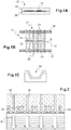
- FIGS. 1A, 1B and 1C illustrate 3 successive treatment stations for a preform made of thermoplastic material.
- FIG. 1B schematically showing a heating enclosure 10, which constitutes an essential treatment station for the method according to the invention. It includes a processing space 12, which has an opposite inlet 14 and outlet 16. Inside the treatment space 12, a thermoplastic composite preform 15 is held horizontally in a fixed position. The preform 15 here has parts of different thicknesses.
- the heating enclosure 10 has, in its upper part, upper infrared radians 18, surmounting the treatment space 12 and oriented towards the latter. It also has in its lower part, below the treatment space 12, lower infrared radians 20 also oriented towards it.
- the enclosure heater 10 comprises a device for projecting a gaseous fluid 22 making it possible to project the gaseous fluid through the infrared radians 18, 20 towards the interior of the treatment space 12 in the direction of the preform 15.
- the projection device 22 includes, for example, injection nozzles 24 extending between the elements of the infrared radians 20, 18.
- the gaseous fluid projected through the device 22 is air.
- a forming mold 26 intended to receive the preform in thermoplastic composite 15 as will be explained below.
- the preform 15 of thermoplastic composite has for example a matrix of polyamide 6, or of polyamide 6.6, and textile reinforcement layers for example of glass fiber or carbon fiber.
- the preform 15 is in the general form of a plate, or of a layered multi-layer preform, unconsolidated, and it is held in a fixed position inside the treatment space 12 on a platform. perforated and not shown.
- a multi-thickness preform presents zones of different thicknesses.
- the infrared radians 18, 20 supply thermal energy by radiation to the preform 15 on its two opposite faces.
- the radiation penetrates through the surface 30 of the preform 15, in its surface layers, over a thickness of the order of a few micrometers, or more, and then the thermal energy is transmitted by conduction inside the preform 15 to reach the heart of the material.
- the intensity of the infrared radians 18, 20 is adjusted so as to be able to bring the temperature of the material of the preform 15 substantially above its melting temperature.
- air is injected through the infrared radian elements 20, 18 according to a flow 28 oriented substantially perpendicular to the surface 30 of the preform 15.
- the installation according to the invention comprises nozzles air injection located between the radians. These air injection nozzles are oriented towards the preform 15, and they are supplied by means of a compressed air network for example.
- the projected air is initially at room temperature, and it makes it possible to cool the surface 30 of the composite preform 15 so as to reduce the oxidation of the material, without hampering the action of infrared radiation through the surface layer.
- a neutral gas of the nitrogen type so as to expel the air and therefore eliminate the presence of oxygen on the surface 30 of the preform 15. In this way, the possibilities of material oxidation are further reduced.
- thermoplastic material makes it ductile in very short times without altering its surface.
- the intensity of the infrared radians 18, 20 is regulated by coming to measure the surface temperature 30 of the preform 15 on the zone of thinner thickness.
- the thermoplastic material can be heated to its melting temperature without degrading it.
- the heating times can be reduced by around 50% compared to the solutions according to the prior art and it is possible to treat composites having different thicknesses and in particular large thicknesses.
- the material of the preform 15 has been brought to a temperature higher than its melting temperature, and this in a homogeneous manner, this is extracted from the heating enclosure 10 through the outlet 16 so that it can be introduced directly to the inside of the forming mold 26.
- the preform 15 is then shaped and then cooled according to a well-known mode of implementation, to provide a piece of rigid composite.
- the preform 15 is preheated by conduction before being introduced inside the heating enclosure 10.
- the installation according to the invention comprises, upstream of the heating enclosure 10, as shown in the Figure 1A , a conduction heating device 32.
- the latter comprises two parallel and mobile heating plates 34, 36 between a position spaced from one another and a position close to one another in which they sandwich the multi-thickness preform 15.
- the heating plates 34, 36 are made of metal and are for example equipped with electrical resistors. In addition, they can themselves be preformed to match the entire surface of the preform 15 and preheat it homogeneously.
- the preform 15 is preheated to a temperature of 180 ° C. in 60 seconds.
- the preform 15 may have parts of different thicknesses, there is no need to have heating plates 34, 36 in shape cooperation with the preform 15. Because in fact, the heating plates 34, 36 are in contact with the parts of greater thickness, and therefore, will favor preheating to the core of these parts, while the parts of thinner thickness will be easily brought to temperature at core later, and more particularly in the heating enclosure 10.
- the preform 15 is transferred inside the heating enclosure 10, in order to be softened in accordance with the provisions indicated above.
- the temperature of the preform 15 tends to decrease during this transfer, only the surfaces are concerned and the infrared radiation from the heating enclosure 10 makes it possible to heat them quickly.
- the preform 15 has a temperature substantially higher than its melting point and evenly distributed in all of its parts despite any differences in thickness.
- the preform 15 is brought from 180 ° C to 250 ° C inside the heating enclosure 10 for a period of less than 60 seconds.
- the time of presence inside the heating enclosure 10 is thus reduced since it is a question of providing thermal energy so that the material of the preform 15 gains a few tens of additional degrees. Consequently, the time of exposure of the material to infrared radiation is reduced and consequently, even more, the risks of oxidation of the surface.
- thermoforming cycle times are reduced, for example for a multi-thickness preform by a polyamide-based composite material, with a maximum thickness of 3.5 mm and a minimum thickness of 1 mm, the cycle time can be of the order of 60 seconds.
- thermoplastic materials in general.
Description
La présente invention se rapporte à un procédé de mise en forme de préforme en matériau thermoplastique et à une installation pour le mettre en œuvre.The present invention relates to a process for shaping a preform of thermoplastic material and to an installation for implementing it.
Des procédés de mise en forme de préformes en matériau polymère thermoplastique, communément dénommés thermoformage, permettent de réaliser des pièces en trois dimensions. Ainsi, on fournit tout d'abord une plaque d'un matériau thermoplastique que l'on rend ductile grâce à des organes de chauffage de type infrarouge. Puis ensuite, on transfère la plaque ductile à l'intérieur d'un moule de formage installé dans une presse et adapté pour pouvoir façonner la pièce en 3 dimensions en déformant la plaque ductile. Enfin, on refroidit la pièce moulée afin que le matériau polymère thermoplastique retrouve sa rigidité, puis on éjecte la pièce du moule de formage.Processes for shaping preforms of thermoplastic polymer material, commonly known as thermoforming, make it possible to produce parts in three dimensions. Thus, firstly a plate of a thermoplastic material is provided which is made ductile by means of infrared type heating members. Then, the ductile plate is transferred inside a forming mold installed in a press and adapted to be able to shape the part in 3 dimensions by deforming the ductile plate. Finally, the molded part is cooled so that the thermoplastic polymer material regains its rigidity, then the part is ejected from the forming mold.
Les organes de chauffage sont installés dans une enceinte et le moule de formage est situé en aval de l'enceinte afin de pouvoir transférer séquentiellement les plaques ductiles de l'enceinte vers le moule de formage en minimisant les pertes énergétiques.The heating elements are installed in an enclosure and the forming mold is located downstream of the enclosure in order to be able to sequentially transfer the ductile plates from the enclosure to the forming mold while minimizing energy losses.
Afin de diminuer le coût de revient de chacune des pièces formées, il est nécessaire de diminuer les temps de fabrication de ces pièces. Aussi, l'étape limitante dans la séquence des transformations est celle du ramollissement du matériau thermoplastique. Aussi, on est poussé à augmenter la puissance des organes de chauffage afin de, précisément, diminuer le temps de cette étape de ramollissement du matériau pour obtenir une plaque ductile. Le risque dans ce cas, est de favoriser l'oxydation de la surface du matériau et partant, de dégrader l'aspect esthétique de cette surface, et à l'extrême, de la brûler. Au surplus, le matériau risque de perdre certaines de ses caractéristiques, notamment mécaniques, mais aussi de tenue due à la perte de ses adjuvants.In order to reduce the cost price of each of the parts formed, it is necessary to reduce the manufacturing times of these parts. Also, the limiting step in the sequence of transformations is that of softening of the thermoplastic material. Also, one is urged to increase the power of the heating members in order to, precisely, decrease the time of this softening step of the material to obtain a ductile plate. The risk in this case is to promote the oxidation of the surface of the material and therefore to degrade the aesthetic appearance of this surface, and in the extreme, to burn it. In addition, the material risks losing some of its characteristics, in particular mechanical, but also resistance due to the loss of its adjuvants.
Aussi, un problème qui se pose et que vise à résoudre la présente invention est de fournir un procédé de mise en forme qui permette de diminuer les temps de cycle de fabrication de pièces thermoformées sans pour autant dégrader le matériau thermoplastique dans lequel elles sont façonnées.Also, a problem which arises and which the present invention aims to solve is to provide a shaping method which makes it possible to reduce the cycle times for manufacturing thermoformed parts without degrading the thermoplastic material in which they are shaped.
Dans ce but, et selon un premier aspect, la présente invention propose un procédé selon la revendication 1.For this purpose, and according to a first aspect, the present invention provides a method according to claim 1.
Ainsi, une caractéristique de l'invention réside dans la mise en œuvre d'un fluide gazeux, par exemple de l'air, que l'on projette sous la forme d'un flux homogène contre la surface de la préforme durant le chauffage du matériau. On fournit ainsi davantage de puissance thermique tout en limitant la montée en température de la surface. De la sorte, et de façon surprenante, il est possible de chauffer le matériau thermoplastique jusqu'à sa température de fusion sans pour autant oxyder sa surface ni la brûler. Partant, le temps de montée en température de la préforme à cœur, est réduit de manière substantielle. Il est par exemple réduit de 50 % dans des conditions où la préforme est relativement épaisse. Au surplus, l'état de surface du matériau ne présente pas de dégradation ni de signes d'oxydation rédhibitoires. Le temps de montée en température de la préforme étant réduit, le temps de cycle complet du formage est réduit d'autant, et partant, le coût de fabrication des pièces en est réduit également.Thus, a characteristic of the invention resides in the use of a gaseous fluid, for example air, which is projected in the form of a homogeneous flow against the surface of the preform during the heating of the material. This provides more thermal power while limiting the temperature rise of the surface. In this way, and surprisingly, it is possible to heat the thermoplastic material to its melting temperature without oxidizing its surface or burning it. Consequently, the time for the temperature of the preform to rise to the core is reduced substantially. It is for example reduced by 50% in conditions where the preform is relatively thick. In addition, the surface condition of the material does not show any degradation or unacceptable signs of oxidation. The preform temperature rise time being reduced, the complete forming cycle time is reduced correspondingly, and consequently, the cost of manufacturing the parts is also reduced.
On entend par matériau composite thermoplastique, un matériau comprenant une matrice faite d'un polymère thermoplastique et d'un élément de renfort, par exemple des couches d'un matériau textile. Le polymère thermoplastique est par exemple un polyamide ou un matériau plus rigide par exemple le poly-ether-ether-cetone. Le matériau textile, est par exemple fait d'un textile tissé en fibre de verre ou de carbone. De la sorte, le matériau composite présente une résistance à la déformation sous contrainte, supérieure à celle d'un matériau thermoplastique exempt de matériau de renfort.The term “thermoplastic composite material” means a material comprising a matrix made of a thermoplastic polymer and of a reinforcing element, for example layers of a textile material. The thermoplastic polymer is for example a polyamide or a more rigid material, for example poly-ether-ether-ketone. The textile material, for example, is made of a textile woven in fiberglass or carbon. In this way, the composite material has a resistance to deformation under stress, higher than that of a thermoplastic material free of reinforcing material.
Selon l'invention entre l'étape a) et l'étape b), on fournit en outre de l'énergie thermique à ladite préforme par conduction, de manière à préchauffer ladite préforme. Ainsi, grâce a cette étape de préchauffage par conduction, en amont de l'étape de chauffage par rayonnement, on apporte déjà une quantité substantielle d'énergie thermique à la préforme, sans dégrader sa surface. La préforme atteint ainsi une température sensiblement inférieure à sa température de fusion, de manière à ce que sa surface ne soit pas rendue collante. De la sorte, en combinant les deux modes d'apport énergétique, par conduction et par rayonnement, on diminue plus encore les temps de cycle de fabrication de la pièce. Aussi, on diminue non seulement les temps de cycle, et par conséquent la productivité, mais au surplus, on diminue la quantité totale d'énergie nécessaire à la mise en forme de la préforme.According to the invention between step a) and step b), thermal energy is also supplied to said preform by conduction, so as to preheat said preform. Thus, thanks to this stage of preheating by conduction, upstream of the stage of heating by radiation, a substantial amount of thermal energy is already provided to the preform, without degrading its surface. The preform thus reaches a temperature substantially lower than its melting temperature, so that its surface is not made sticky. In this way, by combining the two modes of energy supply, by conduction and by radiation, the manufacturing cycle times of the part are further reduced. Also, not only the cycle times, and consequently the productivity, are reduced, but in addition, the total amount of energy necessary for shaping the preform is reduced.
Avantageusement, on projette ledit fluide gazeux selon une direction sensiblement perpendiculaire à la surface de ladite préforme. Une telle orientation, permet un meilleur échange thermique à la surface de la préforme, et partant, permet de la mieux préserver.Advantageously, said gaseous fluid is projected in a direction substantially perpendicular to the surface of said preform. Such an orientation allows better heat exchange on the surface of the preform, and therefore allows it to be better preserved.
En outre, de manière préférentielle, on met en contact ladite préforme avec des plaques chauffées pour fournir de l'énergie thermique par conduction à ladite préforme. Grâce à la mise en contact de la préforme avec les plaques chauffées, les possibilités d'oxydation de la surface du matériau diminuent, puisque la quantité d'air, et partant la quantité d'oxygène, est faible à l'interface. Aussi, l'énergie thermique se propage elle-même plus rapidement par conduction à l'intérieur du matériau pour rejoindre le cœur de la préforme.In addition, preferably, said preform is brought into contact with heated plates to supply thermal energy by conduction to said preform. Thanks to the contacting of the preform with the heated plates, the possibilities of oxidation of the surface of the material decrease, since the quantity of air, and consequently the quantity of oxygen, is low at the interface. Also, the thermal energy propagates itself more quickly by conduction inside the material to reach the heart of the preform.
Au surplus, et selon une variante de réalisation particulièrement avantageuse, à l'étape b), on fournit de l'énergie thermique par rayonnement infrarouge. On entend par rayonnement infrarouge, un rayonnement électromagnétique dont la longueur d'onde est située dans le domaine des longueurs d'onde de l'infrarouge, entre celles correspondant à la lumière visible et celles des micro-ondes. De la sorte, on vient chauffer rapidement et aisément la préforme. Préférentiellement, le rayonnement infrarouge émet dans le domaine des courtes longueurs d'onde, et de faible inertie.In addition, and according to a particularly advantageous embodiment, in step b), thermal energy is supplied by infrared radiation. The term infrared radiation is understood to mean electromagnetic radiation the wavelength of which is situated in the range of infrared wavelengths, between those corresponding to visible light and those of microwaves. In this way, we heat quickly and easily the preform. Preferably, infrared radiation emits in the field of short wavelengths, and of low inertia.
Préférentiellement, à l'étape b), ledit fluide gazeux est de l'air. L'air est en effet intéressant en ce qu'il est d'un coût avantageux. Ainsi qu'on l'expliquera ci-après, dans certaines circonstances, un fluide gazeux inerte est requis pour atténuer plus encore le phénomène d'oxydation de la surface de la préforme en matériau polymère.Preferably, in step b), said gaseous fluid is air. Air is indeed interesting in that it is of an advantageous cost. As will be explained below, in certain circumstances, an inert gaseous fluid is required to further attenuate the phenomenon of oxidation of the surface of the preform made of polymer material.
Selon un autre aspect, la présente invention concerne une installation selon la revendication 5.According to another aspect, the present invention relates to an installation according to claim 5.
Une telle installation de mise en œuvre du procédé tel que décrit ci-dessus, en procure des avantages identiques. De préférence, le dispositif de projection du fluide gazeux est orienté dans une direction sensiblement perpendiculaire à la surface de la préforme. On obtient ainsi un écoulement du fluide gazeux de type turbulent à la surface de la préforme, ce qui permet de préserver plus encore la surface.Such an installation for implementing the method as described above, provides identical advantages. Preferably, the device for projecting the gaseous fluid is oriented in a direction substantially perpendicular to the surface of the preform. One thus obtains a flow of the gaseous fluid of turbulent type on the surface of the preform, which makes it possible to preserve the surface even more.
L'installation comprend un dispositif de chauffage par conduction situé en amont de ladite enceinte de chauffage par rayonnement pour pouvoir fournir de l'énergie thermique à ladite préforme par conduction.The installation comprises a conduction heating device located upstream of said radiation heating enclosure in order to be able to supply thermal energy to said preform by conduction.
Ledit dispositif de chauffage par conduction comprend des plaques chauffées destinées à venir en contact avec ladite préforme pour fournir de l'énergie thermique par conduction à ladite préforme. Ainsi, les plaques chauffées sont mobiles l'une par rapport à l'autre entre une position écartée l'une de l'autre pour pouvoir recevoir la préforme en matériau thermoplastique et une position rapprochée l'une de l'autre où elles viennent s'appliquer en contact contre la préforme. Selon la invention, la préforme est prise entre les plaques chauffées, dans un espace avec une présence d'air limitée, voire un espace confiné si nécessaire, privé d'air au moyen d'un tirage sous vide.Said conduction heating device includes heated plates intended to come into contact with said preform to supply thermal energy by conduction to said preform. Thus, the heated plates are movable relative to each other between a position spaced from each other to be able to receive the preform of material thermoplastic and a position close to each other where they are applied in contact against the preform. According to the invention, the preform is taken between the heated plates, in a space with a limited presence of air, or even a confined space if necessary, deprived of air by means of a vacuum draw.
De plus, ladite enceinte de chauffage par rayonnement comprend des lampes à émission infrarouge.In addition, said radiation heating enclosure comprises infrared emission lamps.
D'autres particularités et avantages de l'invention ressortiront à la lecture de la description faite ci-après d'un mode de réalisation particulier de l'invention, donné à titre indicatif mais non limitatif, en référence aux dessins annexés sur lesquels :
- la
Figure 1A est une vue schématique d'un premier poste d'une installation de mise en forme d'une préforme en matériau composite conforme à l'invention ; - la
Figure 1B est une vue schématique d'un deuxième poste de l'installation succédant au premier représenté sur laFigure 1A ; - la
Figure 1C est une vue schématique d'un troisième poste de l'installation succédant au deuxième représenté sur laFigure 1B ; et, - la
Figure 2 est une vue schématique illustrant des phénomènes observés au deuxième poste de l'installation représenté sur laFigure 1B .
- the
Figure 1A is a schematic view of a first station of an installation for shaping a preform of composite material according to the invention; - the
Figure 1B is a schematic view of a second station of the installation succeeding the first represented on theFigure 1A ; - the
Figure 1C is a schematic view of a third station of the installation succeeding the second shown on theFigure 1B ; and, - the
Figure 2 is a schematic view illustrating phenomena observed at the second station of the installation shown on theFigure 1B .
Les
On se référera tout d'abord à la
En aval de l'enceinte de chauffage 10, est représenté schématiquement sur la
Ainsi, la préforme 15 en composite thermoplastique présente par exemple une matrice en polyamide 6, ou en polyamide 6,6, et des couches de renfort textile par exemple en fibre de verre ou en fibre de carbone. La préforme 15 se présente sous la forme générale d'une plaque, ou d'une préforme nappée multi-épaisseur, non consolidée, et elle est maintenue en position fixe à l'intérieur de l'espace de traitement 12 sur une plate-forme ajourée et non représentée. Une préforme multi-épaisseur, présente des zones de différentes épaisseurs.Thus, the
De la sorte, les radians infrarouges 18, 20 fournissent de l'énergie thermique par rayonnement à la préforme 15 sur ses deux faces opposées.In this way, the
Comme illustré plus en détail sur la
L'intensité des radians infrarouges 18, 20 est ajustée de manière à pouvoir porter la température du matériau de la préforme 15 sensiblement au-delà de sa température de fusion. Simultanément, l'air est injecté à travers les éléments de radians infrarouges 20, 18 selon un flux 28 orienté sensiblement perpendiculairement à la surface 30 de la préforme 15. Pour ce faire, l'installation conforme à l'invention comprend des buses d'injection d'air situées entre les radians. Ces buses d'injection d'air sont orientées vers la préforme 15, et elles sont alimentées grâce a un réseau d'air comprimé par exemple.The intensity of the
L'air projeté est initialement à la température ambiante, et il permet de venir refroidir la surface 30 de la préforme 15 composite de façon à réduire l'oxydation du matériau, sans entraver l'action du rayonnement infrarouge au travers de la couche de surface. Selon une variante de réalisation de l'invention, on projette non pas de l'air ambiant, mais un gaz neutre du type azote, de manière à chasser l'air et partant, éliminer la présence d'oxygène à la surface 30 de la préforme 15. De la sorte, on réduit plus encore les possibilités d'oxydation du matériau.The projected air is initially at room temperature, and it makes it possible to cool the
Ainsi, grâce à la puissance des radians infrarouges 18, 20, permettant de transmettre le maximum d'énergie thermique possible au matériau composite, et à l'action de l'air projeté qui permet de préserver la surface 30 de la préforme 15, on vient ramollir le matériau thermoplastique et le rendre ductile dans des temps très courts sans altérer sa surface.Thus, thanks to the power of
Avantageusement, dans le cas d'une préforme multi-épaisseur, on régule l'intensité des radians infrarouges 18, 20 en venant mesurer la température de surface 30 de la préforme 15 sur la zone de plus faible épaisseur. De la sorte, on peut chauffer le matériau thermoplastique jusqu'à sa température de fusion sans le dégrader. Ainsi, on peut diminuer d'environ 50 % les temps de chauffage par rapport aux solutions selon l'art antérieur et on peut traiter des composites présentant différentes épaisseurs et en particulier des grandes épaisseurs.Advantageously, in the case of a multi-thickness preform, the intensity of the
Après que le matériau de la préforme 15 a été porté à une température supérieure à sa température de fusion, et ce de manière homogène, celle-ci est extraite de l'enceinte de chauffage 10 à travers la sortie 16 pour pouvoir être introduite directement à l'intérieur du moule de formage 26. La préforme 15 est alors mise en forme puis refroidie selon un mode de mise en œuvre bien connu, pour fournir une pièce en composite rigide.After the material of the
Selon un mode de mise en œuvre de l'invention particulièrement avantageux, la préforme 15 est préchauffée par conduction avant d'être introduite à l'intérieur de l'enceinte de chauffage 10. Ainsi, l'installation conforme à l'invention comprend, en amont de l'enceinte de chauffage 10, tel que représenté sur la
Dans cette phase de préchauffage par conduction de la préforme 15, on vient apporter une grande quantité d'énergie thermique à cœur du matériau, et en particulier lorsque la préforme présente une grande épaisseur, notamment avec des plis non consolidés. En effet, on favorise la conduction en limitant les lames d'air entre plis, grâce à la légère pression des plaques chauffantes 34, 36. Celles-ci sont bien évidemment portées à une température inférieure à la température de fusion du matériau thermoplastique. Cela permet non seulement d'éviter l'adhésion, entre les plaques 34, 36 et le matériau de la préforme 15, et au surplus, de ne pas favoriser l'oxydation de la surface 30. Par exemple, pour une préforme multi-épaisseur d'un matériau composite à base de polyamide et d'une épaisseur maximale de 3,5 mm, grâce aux plaques chauffantes 34, 36, la préforme 15 est préchauffée à une température de 180 °C en 60 secondes.In this preheating phase by conduction of the
Bien que la préforme 15 puisse présenter des parties de différentes épaisseurs, il n'est nul besoin d'avoir des plaques chauffantes 34, 36 en coopération de forme avec la préforme 15. Car en effet, les plaques chauffantes 34, 36 sont en contact avec les parties de plus grande épaisseur, et partant, favoriseront le préchauffage à cœur de ces parties, tandis que les parties de plus faibles épaisseur seront aisément portées en température à cœur ultérieurement, et plus particulièrement dans l'enceinte de chauffage 10.Although the
Ainsi, après avoir été préchauffée, la préforme 15 est transférée à l'intérieur de l'enceinte de chauffage 10, afin d'être ramollie conformément aux dispositions indiquées ci-dessus. Bien que la température de la préforme 15 tende à décroître durant ce transfert, seules les surfaces sont concernées et le rayonnement infrarouge de l'enceinte de chauffage 10 permet de les réchauffer rapidement. À l'issue du passage à l'intérieur de l'enceinte de chauffage 10, la préforme 15 présente une température sensiblement supérieure à sa température de fusion et répartie de manière homogène dans toutes ses parties malgré les différences d'épaisseur éventuelles.Thus, after having been preheated, the
Ainsi par exemple, la préforme 15 est portée de 180 °C à 250 °C à l'intérieur de l'enceinte de chauffage 10 pendant une durée inférieure à 60 secondes. Le temps de présence à l'intérieur de l'enceinte de chauffage 10 est ainsi réduit puisqu'il s'agit d'apporter de l'énergie thermique pour que le matériau de la préforme 15 gagne quelques dizaines de degrés supplémentaires. Partant, on réduit le temps d'exposition du matériau au rayonnement infrarouge et par conséquent, plus encore, les risques d'oxydation de la surface.For example, the
La préforme 15 peut ensuite être transférée à l'intérieur du moule de formage 26. Ainsi, grâce à l'installation conforme à l'invention, on diminue les temps de cycle de thermoformage, par exemple pour une préforme multi-épaisseur d'un matériau composite à base de polyamide, d'une épaisseur maximale de 3,5 mm et d'une épaisseur minimale de 1 mm, le temps de cycle peut être de l'ordre de 60 secondes.The
On observera que le procédé, conforme à l'invention, peut également être utilisé pour le formage des matériaux thermoplastiques en général.It will be observed that the method according to the invention can also be used for the forming of thermoplastic materials in general.
Claims (6)
- A method for shaping a preform made of thermoplastic material, of the type comprising the following steps:a) providing a preform (15) made of thermoplastic material having a surface (30) ;b) providing thermal energy by radiation to said preform (15) so as to make it ductile; and,c) shaping said ductile preform (15) within a forming mold (26) ;
wherein, at step a), it is provided a thermoplastic composite material,
and wherein, between step a) and step b), it is further provided thermal energy to said preform (15) by conduction, so as to preheat said preform,
wherein said preform (15) is brought in contact with heated plates (34, 36) to provide thermal energy by conduction to said preform (15), while at step b), simultaneously a gaseous fluid is projected on the surface (30) of said preform (15) to preserve said surface; characterized in that the preform is taken between the heated plates, in a space with a limited air presence, i.e., by means of a vacuum extraction. - The shaping method according to claim 1, characterized in that said gaseous fluid is projected following a direction substantially perpendicular to the surface (30) of said preform (15).
- The shaping method according to any of claims 1 and 2, characterized in that, at step b), thermal energy is provided by infra-red radiation.
- The shaping method according to any of claims 1 to 3, characterized in that, at step b), said gas fluid is air.
- Installation for shaping a preform made of thermoplastic material, comprising, on the one hand, a radiation heating enclosure (10) intended to receive a thermoplastic material preform (15) so as to be able to provide thermal energy by radiation to said preform (15) to make it ductile and, on the other hand, a forming mold (26) located downstream from said heating enclosure (10) to be able to shape said ductile preform ;
wherein it comprises a conduction heating device (32) located upstream to said radiation heating enclosure (10) to be able to provide thermal energy to said preform by conduction ;
wherein said conduction heating device (32) comprises heated plates (34, 36) intended to contact said preform (15) to provide thermal energy to said preform by conduction ;
and wherein it further comprises a device intended to project a gaseous fluid (22) arranged within said radiation heating enclosure (10) to be able to project said gaseous fluid onto the surface (30) of said preform (15), when said preform receives thermal energy by radiation, so as to preserve the surface (30) of said preform (15); characterized in that the installation is adapted to take the preform between the heated plates, in a space with a limited presence of air, i.e. by means of a vacuum extraction. - Installation for shaping according to claim 5, characterized in that said radiation heating enclosure (10) comprises infra-red emission lamps.
Applications Claiming Priority (2)
| Application Number | Priority Date | Filing Date | Title |
|---|---|---|---|
| FR1458839A FR3026044B1 (en) | 2014-09-18 | 2014-09-18 | HOT-SHAPING PROCESS OF THERMOPLASTIC MATERIAL AND INSTALLATION FOR IMPLEMENTING THE SAME |
| PCT/FR2015/052510 WO2016042276A1 (en) | 2014-09-18 | 2015-09-18 | Method for hot-forming a thermoplastic material and implementation facility |
Publications (2)
| Publication Number | Publication Date |
|---|---|
| EP3194143A1 EP3194143A1 (en) | 2017-07-26 |
| EP3194143B1 true EP3194143B1 (en) | 2020-04-22 |
Family
ID=51842629
Family Applications (1)
| Application Number | Title | Priority Date | Filing Date |
|---|---|---|---|
| EP15778364.8A Active EP3194143B1 (en) | 2014-09-18 | 2015-09-18 | Method of heating a thermoplastic object and apparatus therefore |
Country Status (8)
| Country | Link |
|---|---|
| US (1) | US11420379B2 (en) |
| EP (1) | EP3194143B1 (en) |
| JP (1) | JP6781704B2 (en) |
| KR (1) | KR20170054409A (en) |
| CN (1) | CN107073755B (en) |
| CA (1) | CA2960870A1 (en) |
| FR (1) | FR3026044B1 (en) |
| WO (1) | WO2016042276A1 (en) |
Families Citing this family (2)
| Publication number | Priority date | Publication date | Assignee | Title |
|---|---|---|---|---|
| US11457076B2 (en) * | 2017-11-15 | 2022-09-27 | Kyndryl, Inc. | User profile creation for social networks |
| DE102019216720A1 (en) * | 2019-10-30 | 2021-05-06 | Robert Bosch Gmbh | Method and device for producing an electronic module |
Family Cites Families (17)
| Publication number | Priority date | Publication date | Assignee | Title |
|---|---|---|---|---|
| US3114931A (en) * | 1961-10-17 | 1963-12-24 | Ideal Toy Corp | Internal air cooling of blow molded articles |
| EP0305714A3 (en) * | 1983-10-06 | 1989-09-06 | Servichem AG | Device for moulding articles made of thermoplastic material |
| TR22993A (en) * | 1984-04-02 | 1989-01-05 | Sinter Ltd | PROCEDURE AND FACILITY FOR DRYING A SERIES OF IMPRESSED WITH HARDENED ARTIFICIAL RECINE |
| DE8817120U1 (en) * | 1988-04-07 | 1993-02-04 | Vits Maschinenbau Gmbh, 4018 Langenfeld, De | |
| CH679931A5 (en) * | 1990-04-18 | 1992-05-15 | Brandwijk Systems Programming | |
| FR2689442B1 (en) * | 1992-04-03 | 1995-06-23 | Sidel Sa | PROCESS FOR THERMAL CONDITIONING OF PREFORMS IN THERMOPLASTIC MATERIALS AND DEVICE FOR CARRYING OUT SAID METHOD. |
| JPH08500427A (en) * | 1992-08-26 | 1996-01-16 | アー モンフォルツ ゲゼルシャフト ミット ベシュレンクテル ハフツグ ウント コンパニー | Equipment for spraying process gases onto fibrous webs |
| JP2926301B2 (en) * | 1994-04-06 | 1999-07-28 | 住友重機械工業株式会社 | Thermoforming method and apparatus for thermoplastic resin sheet |
| JPH081764A (en) * | 1994-06-24 | 1996-01-09 | Frontier:Kk | Preform heating controlling method for blow molding machine |
| US20020074691A1 (en) * | 1999-09-14 | 2002-06-20 | Robert M Mortellite | High speed method of making plastic film and nonwoven laminates |
| US6072158A (en) * | 1998-10-22 | 2000-06-06 | Konal Engineering And Equipment Inc. | Method and apparatus for heating thin plastic sheet with air diffuser plate preventing sagging of the sheet |
| DE60110431D1 (en) * | 2000-08-11 | 2005-06-02 | Visteon Global Tech Inc | METHOD AND SYSTEM FOR MANUFACTURING A FUEL TANK THROUGH THE FORMING OF THERMOPLASTIC PLATES |
| ITMO20010230A1 (en) * | 2001-11-23 | 2003-05-23 | Sarong Spa | METHOD AND EQUIPMENT FOR FORMING A STRIP OF CONTAINERS |
| DE102006006662A1 (en) * | 2006-02-14 | 2007-08-16 | Westiform Holding Ag | Method for thermoplastic deformation of plastics body involves coating parts of surface of body with heat-repellent and then using heat source to deform non-protected areas |
| CN101786323B (en) * | 2010-02-10 | 2015-04-08 | 崔海徽 | Novel film forming method used in in-moulding decoration technology |
| ES2618000T3 (en) * | 2012-07-24 | 2017-06-20 | Evonik Röhm Gmbh | New conformation process for PMI cellular materials, or composite components obtained from them |
| JP5750426B2 (en) * | 2012-12-10 | 2015-07-22 | 株式会社フロンティア | Biaxial stretch blow molding method and injection / biaxial stretch blow molding system |
-
2014
- 2014-09-18 FR FR1458839A patent/FR3026044B1/en active Active
-
2015
- 2015-09-18 CN CN201580050689.1A patent/CN107073755B/en not_active Expired - Fee Related
- 2015-09-18 US US15/507,291 patent/US11420379B2/en active Active
- 2015-09-18 KR KR1020177007300A patent/KR20170054409A/en unknown
- 2015-09-18 EP EP15778364.8A patent/EP3194143B1/en active Active
- 2015-09-18 WO PCT/FR2015/052510 patent/WO2016042276A1/en active Application Filing
- 2015-09-18 JP JP2017535147A patent/JP6781704B2/en active Active
- 2015-09-18 CA CA2960870A patent/CA2960870A1/en not_active Abandoned
Non-Patent Citations (1)
| Title |
|---|
| None * |
Also Published As
| Publication number | Publication date |
|---|---|
| FR3026044B1 (en) | 2017-06-23 |
| JP2017530040A (en) | 2017-10-12 |
| CN107073755A (en) | 2017-08-18 |
| US11420379B2 (en) | 2022-08-23 |
| JP6781704B2 (en) | 2020-11-04 |
| WO2016042276A1 (en) | 2016-03-24 |
| EP3194143A1 (en) | 2017-07-26 |
| US20170259489A1 (en) | 2017-09-14 |
| FR3026044A1 (en) | 2016-03-25 |
| CA2960870A1 (en) | 2016-03-24 |
| CN107073755B (en) | 2021-02-19 |
| KR20170054409A (en) | 2017-05-17 |
Similar Documents
| Publication | Publication Date | Title |
|---|---|---|
| CA2875233C (en) | Method and device for preheating a mold particularly intended for injection molding | |
| EP2703146B1 (en) | Method for cooling a mould by circulating a heat-transfer fluid in contact with the external face thereof | |
| EP3194143B1 (en) | Method of heating a thermoplastic object and apparatus therefore | |
| EP0542968B1 (en) | Method and use of a device for baking enamel on a metal object, particularly an aluminium object | |
| EP3096940A1 (en) | Method and device for stamping a composite blank with non-consolidated thermoplastic matrix | |
| WO2016151127A1 (en) | Device and method for forming glass | |
| EP3710239B1 (en) | Fibre-application head having a flexible roller provided with a non-stick sleeve | |
| WO2017089659A1 (en) | Fibre application head with flexible roller provided with a metallic exterior layer | |
| EP3281769A1 (en) | Moulding device for carrying out hot moulding and cold moulding methods | |
| WO2010010241A1 (en) | Element for forming a lens, device, element of said device and connector for implementing said method | |
| WO2016139359A1 (en) | Wooden mould with a heating frame | |
| FR3073447A1 (en) | FIBER APPLICATION HEAD WITH AIR BLOWING DEVICE | |
| EP2125642A1 (en) | Glass sheet bending | |
| EP1236554B1 (en) | Method for manufaturing parts from composite materials | |
| FR3106772A1 (en) | SOFT HEATING MAT FOR PREFORMING OR CONSOLIDATION OF COMPOSITE PARTS | |
| CA3053670C (en) | One-piece moulded frame for a composite layup skin | |
| WO2023247498A1 (en) | System and method for crosslinking a continuous mat of mineral and/or vegetable fibers | |
| FR2746214A1 (en) | REFLECTIVE HYBRIDIZATION METHOD AND MACHINE | |
| EP1954471A2 (en) | Method, device and system for producing a corrugated pipe or tube | |
| WO2023152330A1 (en) | Welding method and system | |
| FR3121065A1 (en) | Method of manufacturing a structural part from a preform having improved heating of the preform and associated forming tool | |
| FR2996491A1 (en) | PROCESS FOR PRODUCING THERMOSETTING COMPOSITE PARTS BY DRAPING PREIMPREGNE MATERIAL | |
| FR3094609A1 (en) | Deformable and conformable heated mat | |
| WO2014161833A1 (en) | Welded structural link between a high-performance thermoplastic matrix composite material and an elastomer | |
| EP1249528A1 (en) | Glass fiber product and fabrication process thereof |
Legal Events
| Date | Code | Title | Description |
|---|---|---|---|
| STAA | Information on the status of an ep patent application or granted ep patent |
Free format text: STATUS: THE INTERNATIONAL PUBLICATION HAS BEEN MADE |
|
| PUAI | Public reference made under article 153(3) epc to a published international application that has entered the european phase |
Free format text: ORIGINAL CODE: 0009012 |
|
| STAA | Information on the status of an ep patent application or granted ep patent |
Free format text: STATUS: REQUEST FOR EXAMINATION WAS MADE |
|
| 17P | Request for examination filed |
Effective date: 20170418 |
|
| AK | Designated contracting states |
Kind code of ref document: A1 Designated state(s): AL AT BE BG CH CY CZ DE DK EE ES FI FR GB GR HR HU IE IS IT LI LT LU LV MC MK MT NL NO PL PT RO RS SE SI SK SM TR |
|
| AX | Request for extension of the european patent |
Extension state: BA ME |
|
| RIN1 | Information on inventor provided before grant (corrected) |
Inventor name: CAPON, PHILIPPE Inventor name: CURTHELEY, KARIM Inventor name: CALLENS, CLEMENT Inventor name: DREANO, ELISE Inventor name: LAGOUTTE, ALAIN |
|
| DAV | Request for validation of the european patent (deleted) | ||
| DAX | Request for extension of the european patent (deleted) | ||
| GRAP | Despatch of communication of intention to grant a patent |
Free format text: ORIGINAL CODE: EPIDOSNIGR1 |
|
| STAA | Information on the status of an ep patent application or granted ep patent |
Free format text: STATUS: GRANT OF PATENT IS INTENDED |
|
| RIC1 | Information provided on ipc code assigned before grant |
Ipc: B29C 51/42 20060101AFI20191031BHEP Ipc: B29B 13/02 20060101ALN20191031BHEP Ipc: B29C 35/16 20060101ALN20191031BHEP Ipc: B29C 51/02 20060101ALI20191031BHEP Ipc: B29C 35/08 20060101ALN20191031BHEP Ipc: B29C 51/14 20060101ALI20191031BHEP |
|
| RIC1 | Information provided on ipc code assigned before grant |
Ipc: B29C 51/14 20060101ALI20191108BHEP Ipc: B29C 35/08 20060101ALN20191108BHEP Ipc: B29C 51/02 20060101ALI20191108BHEP Ipc: B29C 35/16 20060101ALN20191108BHEP Ipc: B29C 51/42 20060101AFI20191108BHEP Ipc: B29B 13/02 20060101ALN20191108BHEP |
|
| INTG | Intention to grant announced |
Effective date: 20191127 |
|
| GRAS | Grant fee paid |
Free format text: ORIGINAL CODE: EPIDOSNIGR3 |
|
| GRAA | (expected) grant |
Free format text: ORIGINAL CODE: 0009210 |
|
| STAA | Information on the status of an ep patent application or granted ep patent |
Free format text: STATUS: THE PATENT HAS BEEN GRANTED |
|
| AK | Designated contracting states |
Kind code of ref document: B1 Designated state(s): AL AT BE BG CH CY CZ DE DK EE ES FI FR GB GR HR HU IE IS IT LI LT LU LV MC MK MT NL NO PL PT RO RS SE SI SK SM TR |
|
| REG | Reference to a national code |
Ref country code: CH Ref legal event code: EP |
|
| REG | Reference to a national code |
Ref country code: IE Ref legal event code: FG4D Free format text: LANGUAGE OF EP DOCUMENT: FRENCH |
|
| REG | Reference to a national code |
Ref country code: DE Ref legal event code: R096 Ref document number: 602015051233 Country of ref document: DE |
|
| REG | Reference to a national code |
Ref country code: AT Ref legal event code: REF Ref document number: 1259512 Country of ref document: AT Kind code of ref document: T Effective date: 20200515 |
|
| REG | Reference to a national code |
Ref country code: LT Ref legal event code: MG4D |
|
| REG | Reference to a national code |
Ref country code: NL Ref legal event code: MP Effective date: 20200422 |
|
| PG25 | Lapsed in a contracting state [announced via postgrant information from national office to epo] |
Ref country code: GR Free format text: LAPSE BECAUSE OF FAILURE TO SUBMIT A TRANSLATION OF THE DESCRIPTION OR TO PAY THE FEE WITHIN THE PRESCRIBED TIME-LIMIT Effective date: 20200723 Ref country code: FI Free format text: LAPSE BECAUSE OF FAILURE TO SUBMIT A TRANSLATION OF THE DESCRIPTION OR TO PAY THE FEE WITHIN THE PRESCRIBED TIME-LIMIT Effective date: 20200422 Ref country code: NO Free format text: LAPSE BECAUSE OF FAILURE TO SUBMIT A TRANSLATION OF THE DESCRIPTION OR TO PAY THE FEE WITHIN THE PRESCRIBED TIME-LIMIT Effective date: 20200722 Ref country code: PT Free format text: LAPSE BECAUSE OF FAILURE TO SUBMIT A TRANSLATION OF THE DESCRIPTION OR TO PAY THE FEE WITHIN THE PRESCRIBED TIME-LIMIT Effective date: 20200824 Ref country code: IS Free format text: LAPSE BECAUSE OF FAILURE TO SUBMIT A TRANSLATION OF THE DESCRIPTION OR TO PAY THE FEE WITHIN THE PRESCRIBED TIME-LIMIT Effective date: 20200822 Ref country code: NL Free format text: LAPSE BECAUSE OF FAILURE TO SUBMIT A TRANSLATION OF THE DESCRIPTION OR TO PAY THE FEE WITHIN THE PRESCRIBED TIME-LIMIT Effective date: 20200422 Ref country code: LT Free format text: LAPSE BECAUSE OF FAILURE TO SUBMIT A TRANSLATION OF THE DESCRIPTION OR TO PAY THE FEE WITHIN THE PRESCRIBED TIME-LIMIT Effective date: 20200422 Ref country code: SE Free format text: LAPSE BECAUSE OF FAILURE TO SUBMIT A TRANSLATION OF THE DESCRIPTION OR TO PAY THE FEE WITHIN THE PRESCRIBED TIME-LIMIT Effective date: 20200422 |
|
| REG | Reference to a national code |
Ref country code: AT Ref legal event code: MK05 Ref document number: 1259512 Country of ref document: AT Kind code of ref document: T Effective date: 20200422 |
|
| PG25 | Lapsed in a contracting state [announced via postgrant information from national office to epo] |
Ref country code: RS Free format text: LAPSE BECAUSE OF FAILURE TO SUBMIT A TRANSLATION OF THE DESCRIPTION OR TO PAY THE FEE WITHIN THE PRESCRIBED TIME-LIMIT Effective date: 20200422 Ref country code: HR Free format text: LAPSE BECAUSE OF FAILURE TO SUBMIT A TRANSLATION OF THE DESCRIPTION OR TO PAY THE FEE WITHIN THE PRESCRIBED TIME-LIMIT Effective date: 20200422 Ref country code: LV Free format text: LAPSE BECAUSE OF FAILURE TO SUBMIT A TRANSLATION OF THE DESCRIPTION OR TO PAY THE FEE WITHIN THE PRESCRIBED TIME-LIMIT Effective date: 20200422 Ref country code: BG Free format text: LAPSE BECAUSE OF FAILURE TO SUBMIT A TRANSLATION OF THE DESCRIPTION OR TO PAY THE FEE WITHIN THE PRESCRIBED TIME-LIMIT Effective date: 20200722 |
|
| PG25 | Lapsed in a contracting state [announced via postgrant information from national office to epo] |
Ref country code: AL Free format text: LAPSE BECAUSE OF FAILURE TO SUBMIT A TRANSLATION OF THE DESCRIPTION OR TO PAY THE FEE WITHIN THE PRESCRIBED TIME-LIMIT Effective date: 20200422 |
|
| REG | Reference to a national code |
Ref country code: DE Ref legal event code: R097 Ref document number: 602015051233 Country of ref document: DE |
|
| PG25 | Lapsed in a contracting state [announced via postgrant information from national office to epo] |
Ref country code: ES Free format text: LAPSE BECAUSE OF FAILURE TO SUBMIT A TRANSLATION OF THE DESCRIPTION OR TO PAY THE FEE WITHIN THE PRESCRIBED TIME-LIMIT Effective date: 20200422 Ref country code: CZ Free format text: LAPSE BECAUSE OF FAILURE TO SUBMIT A TRANSLATION OF THE DESCRIPTION OR TO PAY THE FEE WITHIN THE PRESCRIBED TIME-LIMIT Effective date: 20200422 Ref country code: AT Free format text: LAPSE BECAUSE OF FAILURE TO SUBMIT A TRANSLATION OF THE DESCRIPTION OR TO PAY THE FEE WITHIN THE PRESCRIBED TIME-LIMIT Effective date: 20200422 Ref country code: RO Free format text: LAPSE BECAUSE OF FAILURE TO SUBMIT A TRANSLATION OF THE DESCRIPTION OR TO PAY THE FEE WITHIN THE PRESCRIBED TIME-LIMIT Effective date: 20200422 Ref country code: DK Free format text: LAPSE BECAUSE OF FAILURE TO SUBMIT A TRANSLATION OF THE DESCRIPTION OR TO PAY THE FEE WITHIN THE PRESCRIBED TIME-LIMIT Effective date: 20200422 Ref country code: IT Free format text: LAPSE BECAUSE OF FAILURE TO SUBMIT A TRANSLATION OF THE DESCRIPTION OR TO PAY THE FEE WITHIN THE PRESCRIBED TIME-LIMIT Effective date: 20200422 Ref country code: EE Free format text: LAPSE BECAUSE OF FAILURE TO SUBMIT A TRANSLATION OF THE DESCRIPTION OR TO PAY THE FEE WITHIN THE PRESCRIBED TIME-LIMIT Effective date: 20200422 Ref country code: SM Free format text: LAPSE BECAUSE OF FAILURE TO SUBMIT A TRANSLATION OF THE DESCRIPTION OR TO PAY THE FEE WITHIN THE PRESCRIBED TIME-LIMIT Effective date: 20200422 |
|
| PG25 | Lapsed in a contracting state [announced via postgrant information from national office to epo] |
Ref country code: PL Free format text: LAPSE BECAUSE OF FAILURE TO SUBMIT A TRANSLATION OF THE DESCRIPTION OR TO PAY THE FEE WITHIN THE PRESCRIBED TIME-LIMIT Effective date: 20200422 Ref country code: SK Free format text: LAPSE BECAUSE OF FAILURE TO SUBMIT A TRANSLATION OF THE DESCRIPTION OR TO PAY THE FEE WITHIN THE PRESCRIBED TIME-LIMIT Effective date: 20200422 |
|
| PLBE | No opposition filed within time limit |
Free format text: ORIGINAL CODE: 0009261 |
|
| STAA | Information on the status of an ep patent application or granted ep patent |
Free format text: STATUS: NO OPPOSITION FILED WITHIN TIME LIMIT |
|
| 26N | No opposition filed |
Effective date: 20210125 |
|
| PG25 | Lapsed in a contracting state [announced via postgrant information from national office to epo] |
Ref country code: MC Free format text: LAPSE BECAUSE OF FAILURE TO SUBMIT A TRANSLATION OF THE DESCRIPTION OR TO PAY THE FEE WITHIN THE PRESCRIBED TIME-LIMIT Effective date: 20200422 |
|
| REG | Reference to a national code |
Ref country code: CH Ref legal event code: PL |
|
| PG25 | Lapsed in a contracting state [announced via postgrant information from national office to epo] |
Ref country code: SI Free format text: LAPSE BECAUSE OF FAILURE TO SUBMIT A TRANSLATION OF THE DESCRIPTION OR TO PAY THE FEE WITHIN THE PRESCRIBED TIME-LIMIT Effective date: 20200422 |
|
| REG | Reference to a national code |
Ref country code: BE Ref legal event code: MM Effective date: 20200930 |
|
| PG25 | Lapsed in a contracting state [announced via postgrant information from national office to epo] |
Ref country code: LU Free format text: LAPSE BECAUSE OF NON-PAYMENT OF DUE FEES Effective date: 20200918 |
|
| PG25 | Lapsed in a contracting state [announced via postgrant information from national office to epo] |
Ref country code: LI Free format text: LAPSE BECAUSE OF NON-PAYMENT OF DUE FEES Effective date: 20200930 Ref country code: IE Free format text: LAPSE BECAUSE OF NON-PAYMENT OF DUE FEES Effective date: 20200918 Ref country code: CH Free format text: LAPSE BECAUSE OF NON-PAYMENT OF DUE FEES Effective date: 20200930 Ref country code: BE Free format text: LAPSE BECAUSE OF NON-PAYMENT OF DUE FEES Effective date: 20200930 |
|
| PG25 | Lapsed in a contracting state [announced via postgrant information from national office to epo] |
Ref country code: TR Free format text: LAPSE BECAUSE OF FAILURE TO SUBMIT A TRANSLATION OF THE DESCRIPTION OR TO PAY THE FEE WITHIN THE PRESCRIBED TIME-LIMIT Effective date: 20200422 Ref country code: MT Free format text: LAPSE BECAUSE OF FAILURE TO SUBMIT A TRANSLATION OF THE DESCRIPTION OR TO PAY THE FEE WITHIN THE PRESCRIBED TIME-LIMIT Effective date: 20200422 Ref country code: CY Free format text: LAPSE BECAUSE OF FAILURE TO SUBMIT A TRANSLATION OF THE DESCRIPTION OR TO PAY THE FEE WITHIN THE PRESCRIBED TIME-LIMIT Effective date: 20200422 |
|
| PG25 | Lapsed in a contracting state [announced via postgrant information from national office to epo] |
Ref country code: MK Free format text: LAPSE BECAUSE OF FAILURE TO SUBMIT A TRANSLATION OF THE DESCRIPTION OR TO PAY THE FEE WITHIN THE PRESCRIBED TIME-LIMIT Effective date: 20200422 |
|
| P01 | Opt-out of the competence of the unified patent court (upc) registered |
Effective date: 20230810 |
|
| PGFP | Annual fee paid to national office [announced via postgrant information from national office to epo] |
Ref country code: GB Payment date: 20230920 Year of fee payment: 9 |
|
| PGFP | Annual fee paid to national office [announced via postgrant information from national office to epo] |
Ref country code: FR Payment date: 20230905 Year of fee payment: 9 Ref country code: DE Payment date: 20230920 Year of fee payment: 9 |