EP3193777B1 - Aufsatz mit identifikationsmittel für ein körperpflegegerät und körperpflegegerät - Google Patents
Aufsatz mit identifikationsmittel für ein körperpflegegerät und körperpflegegerät Download PDFInfo
- Publication number
- EP3193777B1 EP3193777B1 EP15771251.4A EP15771251A EP3193777B1 EP 3193777 B1 EP3193777 B1 EP 3193777B1 EP 15771251 A EP15771251 A EP 15771251A EP 3193777 B1 EP3193777 B1 EP 3193777B1
- Authority
- EP
- European Patent Office
- Prior art keywords
- mass
- attachment
- identifiable
- spring
- resonant frequency
- Prior art date
- Legal status (The legal status is an assumption and is not a legal conclusion. Google has not performed a legal analysis and makes no representation as to the accuracy of the status listed.)
- Active
Links
- 238000001514 detection method Methods 0.000 claims description 30
- 230000005284 excitation Effects 0.000 claims description 24
- 230000004044 response Effects 0.000 claims description 24
- 238000012544 monitoring process Methods 0.000 claims description 3
- 238000000034 method Methods 0.000 description 24
- 238000012546 transfer Methods 0.000 description 9
- 230000006870 function Effects 0.000 description 7
- 230000008901 benefit Effects 0.000 description 6
- 238000013461 design Methods 0.000 description 5
- 238000005259 measurement Methods 0.000 description 5
- 230000004913 activation Effects 0.000 description 4
- 230000007246 mechanism Effects 0.000 description 4
- 239000000463 material Substances 0.000 description 3
- 230000008878 coupling Effects 0.000 description 2
- 238000010168 coupling process Methods 0.000 description 2
- 238000005859 coupling reaction Methods 0.000 description 2
- 230000001419 dependent effect Effects 0.000 description 2
- 238000010586 diagram Methods 0.000 description 2
- 230000004907 flux Effects 0.000 description 2
- 238000012986 modification Methods 0.000 description 2
- 230000004048 modification Effects 0.000 description 2
- 230000008569 process Effects 0.000 description 2
- 230000001680 brushing effect Effects 0.000 description 1
- 239000012636 effector Substances 0.000 description 1
- 230000000694 effects Effects 0.000 description 1
- 238000002847 impedance measurement Methods 0.000 description 1
- 230000006872 improvement Effects 0.000 description 1
- 230000003287 optical effect Effects 0.000 description 1
- 230000003534 oscillatory effect Effects 0.000 description 1
- 238000012545 processing Methods 0.000 description 1
- 239000007787 solid Substances 0.000 description 1
- 238000010408 sweeping Methods 0.000 description 1
- 238000012360 testing method Methods 0.000 description 1
- 238000002604 ultrasonography Methods 0.000 description 1
Images


Classifications
-
- A—HUMAN NECESSITIES
- A61—MEDICAL OR VETERINARY SCIENCE; HYGIENE
- A61C—DENTISTRY; APPARATUS OR METHODS FOR ORAL OR DENTAL HYGIENE
- A61C17/00—Devices for cleaning, polishing, rinsing or drying teeth, teeth cavities or prostheses; Saliva removers; Dental appliances for receiving spittle
- A61C17/16—Power-driven cleaning or polishing devices
- A61C17/22—Power-driven cleaning or polishing devices with brushes, cushions, cups, or the like
- A61C17/32—Power-driven cleaning or polishing devices with brushes, cushions, cups, or the like reciprocating or oscillating
- A61C17/34—Power-driven cleaning or polishing devices with brushes, cushions, cups, or the like reciprocating or oscillating driven by electric motor
- A61C17/3409—Power-driven cleaning or polishing devices with brushes, cushions, cups, or the like reciprocating or oscillating driven by electric motor characterized by the movement of the brush body
- A61C17/3418—Rotation around the axis of the toothbrush handle
-
- A—HUMAN NECESSITIES
- A61—MEDICAL OR VETERINARY SCIENCE; HYGIENE
- A61C—DENTISTRY; APPARATUS OR METHODS FOR ORAL OR DENTAL HYGIENE
- A61C17/00—Devices for cleaning, polishing, rinsing or drying teeth, teeth cavities or prostheses; Saliva removers; Dental appliances for receiving spittle
- A61C17/16—Power-driven cleaning or polishing devices
- A61C17/22—Power-driven cleaning or polishing devices with brushes, cushions, cups, or the like
- A61C17/32—Power-driven cleaning or polishing devices with brushes, cushions, cups, or the like reciprocating or oscillating
- A61C17/34—Power-driven cleaning or polishing devices with brushes, cushions, cups, or the like reciprocating or oscillating driven by electric motor
- A61C17/3409—Power-driven cleaning or polishing devices with brushes, cushions, cups, or the like reciprocating or oscillating driven by electric motor characterized by the movement of the brush body
- A61C17/3481—Vibrating brush body, e.g. by using eccentric weights
-
- H—ELECTRICITY
- H02—GENERATION; CONVERSION OR DISTRIBUTION OF ELECTRIC POWER
- H02K—DYNAMO-ELECTRIC MACHINES
- H02K33/00—Motors with reciprocating, oscillating or vibrating magnet, armature or coil system
Definitions
- the present embodiments relate generally to personal care appliances and more particularly, to a mass-spring identifiable attachment for a personal care appliance and a method of implementing the same.
- a resonant drive is often applied for driving an attachment, such as a brush head.
- the use of a resonant drive in a power toothbrush makes it possible to reach operating frequencies of 200-400 Hz.
- the resonant system of the power toothbrush comprises a mechanical mass-spring which is driven by an actuator.
- An electronic driving circuit of the power toothbrush operates the resonant system close to its resonance, so that the stroke stability and the efficiency of the brush head become as high as possible.
- Power toothbrushes generally make use of disposable brush heads.
- a disposable brush head is meant for use by one person; however, the handle of the power toothbrush can be used by more than one person in a given family. In the later instance, each person has to recognize his/her own disposable brush head. To assist the users, the disposable brush heads are sometimes provided with a specific distinguishing mark, such as different color rings.
- a conductive connection can be used, or a wireless link.
- an optical system could be used for the data transfer, or a system that works with coupled (i.e., magnetic) fields.
- a principal disadvantage of such methods is that they are costly and/or require a lot of space in the context of a personal care appliance, such as a power toothbrush.
- US 2010/237720 A1 discloses an oscillatory device incorporating a limited angle torque motor capable of oscillating one or more end effectors.
- the device may additionally incorporate an ultrasound transducer and/or a waveguide structure.
- the device may comprise a power toothbrush, in which case the device may be designed to enable detection and identification of brush heads having different inertia properties, for the purpose of identifying different users and, optionally, matching different protocols or programmed features to the different users and/or brush heads.
- a personal care appliance which comprises a handle, an attachment, and a controller.
- the handle includes an actuator and drive shaft.
- the attachment has a body with a principal axis extending between a proximal end and a distal end thereof, wherein the proximal end couples to the drive shaft.
- the attachment further includes a mass-spring identifiable assembly having at least one identifiable resonant frequency in response to a given excitation, wherein the at least one identifiable resonant frequency comprises a resonant frequency selected from at least two different resonant frequencies.
- the controller is configured to control the attachment, via the actuator, over a predefined range of frequencies that includes the given excitation.
- the controller is further configured, in at least a detection mode, to uniquely recognize the attachment via detecting a presence of the at least one identifiable resonant frequency of the mass-spring identifiable assembly of the attachment in response to the given excitation.
- the mass-spring identifiable assembly comprises a ring mass-spring component including a distinct mass and spring component having a ring mass centered about the principal axis and mechanically coupled to the body via leaf springs.
- the actuator comprises a permanent magnet resonant actuator having a principal coil, wherein the permanent magnet resonant actuator with principal coil is operable as a sensing device.
- the controller is further configured to use the permanent magnet resonant actuator with principal coil as the sensing device in the detecting of a presence of an identifiable resonant frequency of a mass-spring identifiable assembly.
- the mass-spring identifiable assembly comprises a ring mass-spring component including a distinct mass and spring component.
- the distinct mass and spring component includes a ring mass centered about the principal axis and mechanically coupled to the body via leaf springs.
- the leaf springs comprise one selected from the group consisting of (i) leaf springs that extend radially outward from an outer perimeter surface of the ring mass and (ii) leaf springs that extend from at least one surface of the ring mass in a direction along the principal axis.
- the personal care appliance further comprises a sensing coil disposed adjacent to the drive shaft within the handle.
- the controller is further configured to use the sensing coil in the detecting of the presence an identifiable resonant frequency of a mass-spring identifiable assembly.
- the controller of the personal care appliance is further configured to perform, in a user mode, at least one operation or function of the personal care appliance in response to uniquely recognizing the attachment via the detection mode detecting the presence of the at least one identifiable resonant frequency of the mass-spring identifiable assembly.
- the user mode comprises at least one selected from the group consisting of: (i) automatically selecting personalized user settings, (ii) monitoring a user behavior, (iii) collecting historic data, and (iv) any combination thereof.
- the personal care appliance wherein the controller, in at least the detection mode, is configured to recognize an attachment that comprises one of at least two distinct disposable units.
- the predefined range of frequencies, over which the controller controls the attachment further comprises a principal functional frequency, wherein the at least one identifiable resonant frequency of the mass-spring identifiable assembly comprises a resonant frequency selected so that it is not disturbed by the principal functional frequency.
- the at least one identifiable resonant frequency comprises at least one resonant frequency selected from the group consisting of (i) a resonant frequency less than the first frequency (e.g., ⁇ 200 Hz), (ii) a resonant frequency greater than the second frequency (e.g., >300 Hz), and (iii) a resonant frequency for which its detection is immune from a power transfer associated with an operation of the personal care appliance at the principal functional frequency, i.e., a resonant frequency not disturbed by the principal functional frequency of the personal care appliance.
- the embodiments of the present disclosure advantageously enable, not only the user, but also the personal care appliance handle to recognize the disposable attachment. Doing so opens up several possibilities.
- the handle can give the user feedback about the status of the disposable attachment (e.g., lifetime, integral operating time, or attachment behavior).
- the handle can automatically select special personal settings, as soon the disposable attachment is connected to the handle (e.g., dedicated movement, amplitude or frequency of the movement).
- the handle can also monitor use behaviour (e.g., a parent can see how often and/or how long their child brushes their teeth).
- an attachment for a personal care appliance which comprises a body with a principal axis extending between a proximal end and a distal end thereof, wherein the proximal end couples to a drive shaft of an actuator of the personal care appliance.
- the attachment further comprises a mass-spring identifiable assembly coupled to or coupled with the body, the mass-spring identifiable assembly having at least one identifiable resonant frequency in response to a given excitation, wherein the at least one identifiable resonant frequency comprises a resonant frequency selected from at least two different resonant frequencies, and wherein the mass-spring identifiable assembly comprises a ring mass-spring component including a distinct mass and spring component having a ring mass centered about the principal axis and mechanically coupled to the body via leaf springs.
- the attachment is preferably disposed to interact with the appliance, wherein a controller of the personal care appliance is configured to control the body and mass-spring identifiable assembly, via the actuator, over a predefined range of frequencies that includes the given excitation.
- the controller is further configured, in at least a detection mode, to uniquely recognize the attachment via detecting a presence of the at least one identifiable resonant frequency of the mass-spring identifiable assembly of the attachment in response to the given excitation.
- the mass-spring identifiable assembly comprises a ring mass-spring component including a distinct mass and spring component.
- the distinct mass and spring component includes a ring mass centered about the principal axis and mechanically coupled to the body via leaf springs.
- the leaf springs comprise one selected from the group consisting of (i) leaf springs that extend radially outward from an outer perimeter surface of the ring mass and (ii) leaf springs that extend from at least one surface of the ring mass in a direction along the principal axis.
- the predefined range of frequencies, over which the controller controls the body and mass-spring identifiable assembly of the attachment, via the actuator, further comprises a principal functional frequency, wherein the at least one identifiable resonant frequency of the mass-spring identifiable assembly comprises a resonant frequency selected so that it is not disturbed by the principal functional frequency.
- the at least one identifiable resonant frequency comprises at least one resonant frequency selected from the group consisting of (i) a resonant frequency less than the first frequency, (ii) a resonant frequency greater than the second frequency, and (iii) a resonant frequency for which its detection is immune from a power transfer associated with an operation of the personal care appliance at the principal functional frequency, i.e., a resonant frequency not disturbed by the principal functional frequency of the personal care appliance.
- a method of implementing mass-spring identification in a personal care appliance comprises providing a handle including an actuator and drive shaft.
- the method further comprises providing an attachment having a body with a principal axis extending between a proximal end and a distal end thereof, wherein the proximal end couples to the drive shaft, the attachment further including a mass-spring identifiable assembly having at least one identifiable resonant frequency in response to a given excitation, wherein the at least one identifiable resonant frequency comprises a resonant frequency selected from at least two different resonant frequencies.
- the method further comprises controlling, via the actuator and a controller, the attachment over a predefined range of frequencies that includes the given excitation, and further controlling, in at least a detection mode, to uniquely recognize the attachment via detecting a presence of the at least one identifiable resonant frequency of the mass-spring identifiable assembly of the attachment in response to the given excitation.
- the mass-spring identifiable assembly comprises at least one selected from the group consisting of: (i) a distinct mass and spring component, (ii) a ring mass, and (iii) a three-dimensional configuration of the body.
- the ring mass is centered about the principal axis and mechanically coupled to the body via leaf springs.
- the leaf springs comprise one selected from the group consisting of (i) leaf springs that extend radially outward from an outer perimeter surface of the ring mass and (ii) leaf springs that extend from at least one surface of the ring mass in a direction along the principal axis.
- the three-dimensional configuration of the body includes at least one feature configured to exhibit a resonant mode of the body that corresponds to the at least one identifiable resonant frequency of the mass-spring identifiable assembly.
- the predefined range of frequencies, over which the controller controls the attachment further comprises a principal functional frequency, wherein the at least one identifiable resonant frequency of the mass-spring identifiable assembly comprises a resonant frequency selected so that it is not disturbed by the principal functional frequency.
- the at least one identifiable resonant frequency comprises at least one resonant frequency selected from the group consisting of (i) a resonant frequency less than the first frequency, (ii) a resonant frequency greater than the second frequency, and (iii) a resonant frequency for which its detection is immune from a power transfer associated with an operation of the personal care appliance at the principal functional frequency.
- the embodiments of the present disclosure advantageously solve the problem of providing an inexpensive solution for recognizing a disposable attachment and for which the solution also does not require a lot of extra space.
- predefined mass-spring resonant properties are used in conjunction with a disposable brush head, and which can be recognized by control electronics in the power toothbrush handle via the main actuator of the power toothbrush handle.
- An advantage of this solution is that it provides a very inexpensive way of recognizing different disposable brush heads that doesn't require a lot of extra space.
- prescribed changes are made on the bristle side, i.e., with respect to the disposable brush head.
- the disposable brush head is provided with a pre-defined mass-spring mechanism in its design, which gives the corresponding brush head special resonant properties.
- changes are also implemented on the handle side.
- the changes on the handle side include changes in the software and electronics (e.g., a coil on a printed circuit board, PCB).
- FIG. 1 there is shown a schematic longitudinal sectional view of a personal care appliance 10 that comprises a handle 12, and an attachment 14, according to an embodiment of the present disclosure.
- the handle 12 includes a controller 16, an actuator 20 and drive shaft 22.
- the drive shaft 22 extends outside the handle 12 at a distal end thereof.
- the attachment 14 has a body 30 with a principal axis 32 extending between a proximal end and a distal end thereof, wherein the proximal end couples, via a press fit or other suitable coupling mechanism, to the drive shaft 22 extending from the distal end of handle 12.
- the attachment 14 includes a plurality of bristles 38 located at the distal end thereof.
- the attachment 14 further includes a mass-spring identifiable assembly 40 having at least one identifiable resonant frequency in response to a given excitation, wherein the at least one identifiable resonant frequency comprises a resonant frequency selected from at least two different resonant frequencies, as will be discussed further herein.
- the controller 16 e.g., battery and control electronics
- the controller 16 is configured to control the attachment 14, via the actuator 20, to produce one or more of various mechanical stimulus (e.g., rotary sweeping movement having a given resonant frequency).
- the controller 16 is further configured, in at least a detection mode, to uniquely recognize the attachment 14 via detecting a presence of the at least one identifiable resonant frequency of the mass-spring identifiable assembly 40 of the attachment 14 in response to the given excitation, wherein the mass-spring identifiable assembly 40 comprises at least one of: (i) a ring mass-spring component; and (ii) a three-dimensional configuration of the body 30.
- the mass-spring identifiable assembly 40 comprising only a three-dimensional configuration of the body 30 is outside of the scope of the present invention.
- the given excitation can include at least one of a plurality of resonant frequencies.
- the actuator 20 comprises a permanent-magnet resonant actuator that functions as a means that transfers energy from the electrical domain to the mechanical domain.
- the permanent-magnet resonant actuator can also act as a generator, whereby mechanical speed and torque can be recognized as voltages and currents in the electrical domain.
- the permanent-magnet resonant actuator can be used as a measuring device that senses the mechanical properties of the load connected to the personal care appliance 10, i.e., the attachment 14.
- the actuator 20 comprises a permanent magnet resonant actuator having a principal coil (not shown), wherein the permanent magnet resonant actuator with principal coil is operable as a sensing device.
- the controller 16 is further configured to use the permanent magnet resonant actuator with principal coil as the sensing device in the detecting of a presence of an identifiable resonant frequency of a mass-spring identifiable assembly 40, e.g., corresponding to mass-spring properties of the attachment 14 coupled to the drive shaft 22, as will be discussed further herein.
- the controller 16 uses the permanent magnet resonant actuator with principal coil as a sensing device for determining an identifiable resonant frequency of the attachment 14.
- attachment 14 comprises a replaceable attachment that is subject to being replaced after a given useful lifetime or use duration.
- the personal care appliance 10 can comprise, for example, a power toothbrush.
- the personal care appliance 10 further comprises an activation mechanism 26 (e.g., button, switch, or equivalent) that is operable between (i) an OFF state and (ii) at least one activation ON state.
- the at least one activation ON state includes a suitable procedure and/or control routine with respect to uniquely recognizing a given attachment in conjunction with a care routine and/or operation.
- a separate actuator (not shown) from the activation mechanism 26 can alternatively be employed to perform this function.
- controller 16 further comprises a motor controller for controlling an operation or operations of the actuator 20 to produce a desired mechanical stimulus according to the requirements of a given personal care appliance user routine.
- the controller is configured for controlling an operation of the actuator between an OFF state and at least one of (i) a first personal care appliance user routine and (ii) a second personal care appliance user routine.
- Figure 2 illustrates a simple equivalent circuit representation 44 of a typical resonant actuator 20.
- the mechanical effects are given as equivalent electrical components (e.g., using electrical symbols, R, L, C, Load).
- the input impedance of the actuator 20 is not only dependent on the electrical components, but also on the mechanical components. Therefore, the electrical impedance at the actuator input will also be a function of the mechanical parts attached to its' output.
- the equivalent circuit representation 44 includes an electrical driver 46, actuator resistance R ACT , actuator inductance L ACT , a transformer (K:1), a spring, a rotor capacitance C ROTOR , an attachment capacitance C ATTACH , and a process load (PROCESS LOAD).
- a resonance frequency of a mechanical mass-spring system on the output of the actuator is detectable in the actuator input impedance.
- the actuator is used as a kind of sensor, in order to determine a property of the attachment coupled to the output of the actuator 20.
- the inventors have discovered a way to add a specific mechanical property to a brush head of a personal care appliance that can be well measured by this method. If various attachments have mass-springs of different resonant frequencies, the attachments can be distinguished from one another by the measuring method.
- the predefined range of frequencies, over which the controller controls the attachment comprises a principal functional frequency in a range between (i) a first frequency and (ii) a second frequency, higher than the first frequency (e.g., 200 to 300 Hz), and an identifiable resonant frequency in a range selected from the group consisting of (i) a resonant frequency less than the first frequency (e.g., ⁇ 200 Hz) and (ii) a resonant frequency greater than the second frequency (e.g., >300 Hz).
- Other frequencies and ranges are possible, according to the particular implementation of the personal care appliance.
- the at least one identifiable resonant frequency of the mass-spring identifiable assembly can comprise a resonant frequency selected so that it is not disturbed by the principal functional frequency.
- the at least one identifiable resonant frequency of the mass-spring identifiable assembly can comprise a resonant frequency for which its detection is immune from a power transfer associated with an operation of the personal care appliance at the principal functional frequency.
- the mass-spring identifiable assembly 40 comprises at least one selected from the group consisting of: (i) a ring mass-spring component and (ii) a three-dimensional configuration (i.e., shape) of the body 30 (30A, 30B).
- the mass-spring identifiable assembly 40 comprising only a three-dimensional configuration of the body 30 is outside of the scope of the present invention.
- the mass-spring identifiable assembly 40 that comprises a spring component 50 that includes a ring mass 51
- the ring mass 51 is centered about the principal axis 32 and mechanically coupled to the body 30 via leaf springs 52.
- the leaf springs 52 comprise one selected from the group consisting of (i) leaf springs 52 that extend radially outward from an outer perimeter surface of the ring mass 51 and (ii) leaf springs 52 that extend from at least one surface of the ring mass 51 in a direction along the principal axis.
- the mass-spring identifiable assembly 40 can comprise a click-on recognizable body (which acts like a mass spring).
- the shape of such a click-on recognizable body does not necessarily need to be ring shaped but can be any shape, as long as its resonant frequency is recognizable. Any solid body has natural resonant frequencies (modes). The embodiments of the present disclosure make use of these frequencies to be recognized.
- the design of the attachment e.g., the brush head for a power toothbrush
- the design of the attachment is such that resonant mode of the attachment occur at a desired frequency.
- FIGs 4 and 5 are perspective views of an embodiment of the attachment 14 and mass-spring identifiable system 40 of the present invention.
- the mass-spring identifiable system 40 comprises a spring component 50 that includes ring mass 51 which is connected to the attachment 14 via leaf springs 52.
- This design of the spring component 50 includes three (3) leaf springs 52, holding an inertial ring mass 51.
- Figure 5 is a perspective image view of the attachment 14 and mass-spring identifiable assembly 40 coupled together according to an embodiment of the present disclosure.
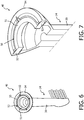
- Figure 6 there is shown a perspective view of the attachment 14 and mass-spring identifiable assembly 40 coupled together according to another embodiment of the present disclosure.
- Figure 7 shows a sectional perspective image view of the attachment 14 and mass-spring identifiable assembly 40 of Figure 6 according to an embodiment of the present disclosure.
- the mass-spring is located within an inside portion of the brush head and only a color ring 54 will be visible for the user or consumer, in contrast to the arrangement shown in Figure 5 .
- An advantage of the embodiment of Figure 6 and Figure 7 is that the main portion of the attachment can remain the same and only the mass-spring identifiable assembly 40 (e.g., in the form of a mass-spring "click-on”) is user specific.
- a mass-spring identifiable assembly 40 is part of the three-dimensional configuration of the attachment body 30 (generally indicated by reference numerals 40A and 40B in Figures 8A and 8B ).
- the resonant mode of the body corresponds to (i.e., is similar to) at least one identifiable resonant frequency of the mass-spring identifiable assembly (40).
- the mass-spring identifiable assembly 40 comprises the three-dimensional configuration (30A,30B) of the body, wherein the three-dimensional configuration of the body includes at least one feature (40A,40B) configured to exhibit a resonant mode of the body that corresponds to the at least one identifiable resonant frequency of the mass-spring identifiable assembly 40.
- FIG. 8A and 8B there is shown is a longitudinal sectional view of an attachment 14A, 14B including a mass-spring identifiable assembly 40A, 40B according to another embodiment of the present disclosure.
- the embodiments of the present disclosure could also detect the specific resonance provided via the body design 30A, 30B. In addition, this embodiment would be more visible to the consumer.
- circuit impedance induced by the resonant actuator can be dominated by the actuator resistance and self-inductance. As a result, it may become difficult to distinguish the resonant peaks of the added mass-spring system.
- a measurement more close to the moving part is implemented.
- an improvement can be made by placing a sensing coil in the actuator, which receives the time-varying flux caused by the mechanical motion, as will be discussed below in connection with Figure 9 .
- the actuator can be provided with a sensing coil 58 for detecting the mass-spring identifiable assembly 40 resonance.
- FIG. 9 there is shown an equivalent schematic circuit diagram 56 representation of ta personal care appliance including a mass-spring identifiable assembly 40, and a sensing coil 58, according to an embodiment of the present disclosure.
- a sensing coil is disposed adjacent to the drive shaft within the handle, wherein the controller is further configured to use the sensing coil in the detecting of the presence an identifiable resonant frequency of a mass-spring identifiable assembly.
- the sensing coil is utilized by the controller for detecting the presence of the at least one identifiable resonant frequency of the mass-spring identifiable assembly 40.
- the sensing coil 58 is coupled to the magnetic system, so that it optimally receives the time-varying flux from the moving parts.
- the resistance (R S ) and self-inductance (L S ) of the sensing coil do not influence the signal, because the current in this sensing coil is zero. However, the sensing coil will be coupled to the main coil. Nevertheless, the resonance peak of the added mass-spring identifiable assembly 40 is better visible now, i.e., identifiable.
- the sweep generator 62 performs a frequency sweep over a range where the resonances are to be expected. These resonance frequencies are preferably chosen to be higher or lower than the main resonance of the system. In this manner, the operating resonance of the personal care appliance is not disturbing the frequency sweep measurement.
- an identifiable resonance frequency of the added mass-spring identifiable assembly 40 of the embodiments of the present disclosure is selected such that the principal functional resonance of the personal care appliance does not disturb the detection of the identifiable resonance frequency.
- the identifiable resonant frequency is thus selected as a resonant frequency for which its detection is immune from a power transfer associated with an operation of the personal care appliance at the principal functional frequency.
- Figure 10 (10A) is a graph representation view (i.e., a frequency sweep measurement) and (10B) a perspective image view of an attachment without a mass-spring identifiable assembly.
- Figure 11 (11A) is a graph representation view (i.e., a frequency sweep measurement) and (11B) a perspective image view of an attachment including a mass-spring identifiable assembly 40 according to an embodiment of the present disclosure.
- Figure 10A illustrates a voltage gain (dB) curve 64 over a frequency range of 100 to 1000 Hz for an attachment without a mass-spring identifiable assembly of Figure 10B.
- Figure 11A illustrates a voltage gain (dB) curve 66 over a frequency range of 100 to 1000 Hz for an attachment with a mass-spring identifiable assembly 40 of Figure 11B .
- normal operation is conducted at a principal functional frequency proximate the large resonant peak 65 shown in Figures 10A and 11A , between 200 to 300 Hz, and more particularly, at about 260-290 Hz.
- the execution of a frequency sweep for the detection mode can be implemented prior to use of the personal care appliance by a user, i.e., in response to the personal care appliance being picked up by the user.
- Motion detectors can be included within the handle for sensing the motion of the handle being picked up.
- Another possibility would be to perform a detection sweep every second in response to a motion sensor sensing a motion trigger and the personal care appliance not yet being switched on.
- Yet another possibility would be to perform a detection sweep in response to a user putting on another brush head, i.e., in response to detecting a higher than normal axial force.
- Other implementations of the detection mode are also possible.
- the controller drives the actuator to perform the detection sweep directly in response to a sensed actuation of the personal care appliance ON-button. After the detection sweep is finished and the controller completes the attachment detection, the controller again switches on the main actuator of the personal care appliance at the normal brushing frequency, whereupon the normal operation begins.
- FIG. 10A One embodiment of the particular operating frequency range of the embodiments of the present disclosure is also shown in Figures 10A and 11A .
- a large resonant frequency peak, indicated by reference numeral 65, at about 260 Hertz is near the normal use operational frequency of the device (i.e., near the principal functional frequency).
- Figure 11A further illustrates another resonant peak 68 at about 850 Hz which identifies the attachment 14 with mass-spring identifiable assembly 40.
- the controller 16 of the personal care appliance 10 is further configured to perform, in a user mode, at least one operation or function of the personal care appliance in response to uniquely recognizing the attachment via the detection mode detecting the presence of at least one identifiable resonant frequency of the mass-spring identifiable assembly 40, wherein the at least one identifiable resonant frequency comprises a resonant frequency selected from at least two different resonant frequencies.
- the controller 16 responsive to recognizing the attachment 14, the controller 16 operates in a specific user mode of the personal care appliance as a function of the attachment recognized.
- the user mode comprises at least one selected from the group consisting of: (i) automatically selecting personalized user settings, (ii) monitoring a user behavior, (iii) collecting historic data, and (iv) any combination thereof.
- Historic data can include, for example, device wear data, useful lifetime, etc.
- the system has been used for a power toothbrush, wherein the controller, in at least the detection mode, is configured to recognize an attachment that comprises a brush head selected from at least two distinct disposable brush heads.
- the system could also be used for other personal care appliances with resonant actuators or pumps.
- the personal care appliance could comprise a shaver with "unit recognition," etc.
- the controller in at least the detection mode, is configured to recognize an attachment that comprises a shaver-unit selected from at least two distinct disposable shaver-units.
- a disposable shaver-unit comprises a configuration of multiple shaver heads that include cutting elements.
- a shaver unit can comprise three heads. Other configurations are also possible.
- an attachment 14 for a personal care appliance 10 which comprises a body 30 with a principal axis 32 extending between a proximal end and a distal end thereof, wherein the proximal end couples to a drive shaft 22 of an actuator 20 of the personal care appliance 10.
- the attachment 14 further comprises a mass-spring identifiable assembly 40 coupled to or coupled with the body 30, the mass-spring identifiable assembly having one of at least two identifiable resonant frequencies in response to a given excitation, wherein a controller 16 of the personal care appliance 10 is configured to control the body 30 and mass-spring identifiable assembly 40, via the actuator 20, over a predefined range of frequencies that includes the given excitation, and wherein the controller 16 is further configured, in at least a detection mode, to uniquely recognize the attachment 14 via detecting a presence of one of the at least two identifiable resonant frequencies of the mass-spring identifiable assembly of the attachment in response to the given excitation.
- the predefined range of frequencies, over which the controller 16 controls the body 30 and mass-spring identifiable assembly 40, via the actuator 20, further comprises a principal functional frequency.
- the principal functional frequency occurs between (i) a first frequency and (ii) a second frequency that is higher than the first frequency, and an identifiable resonant frequency of the at least one identifiable resonant frequency comprises at least one resonant frequency selected from the group consisting of (i) a resonant frequency less than the first frequency, (ii) a resonant frequency greater than the second frequency, and (iii) a resonant frequency for which its detection is immune from a power transfer associated with an operation of the personal care appliance at the principal functional frequency.
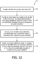
- a method 70 of implementing mass-spring identification in a personal care appliance comprises the acts of providing a handle including an actuator and drive shaft (Step 72). The method further comprises coupling an attachment having a mass-spring identifiable assembly to the handle via the drive shaft (Step 74). The attachment further including a mass-spring identifiable assembly having one of at least two identifiable resonant frequencies in response to a given excitation.
- the method further comprises controlling, via the actuator and a controller, the attachment over a predefined range of frequencies that includes the given excitation (Step 76), and further controlling, in at least a detection mode, to uniquely recognize the attachment via detecting a presence of one of the at least two identifiable resonant frequencies of the mass-spring identifiable assembly of the attachment in response to the given excitation (Step 78).
- any reference signs placed in parentheses in one or more claims shall not be construed as limiting the claims.
- the word “comprising” and “comprises,” and the like, does not exclude the presence of elements or steps other than those listed in any claim or the specification as a whole.
- the singular reference of an element does not exclude the plural references of such elements and vice-versa.
- One or more of the embodiments may be implemented by means of hardware comprising several distinct elements, and/or by means of a suitably programmed computer. In a device claim enumerating several means, several of these means may be embodied by one and the same item of hardware.
- the mere fact that certain measures are recited in mutually different dependent claims does not indicate that a combination of these measures cannot be used to an advantage.
Landscapes
- Health & Medical Sciences (AREA)
- Dentistry (AREA)
- Epidemiology (AREA)
- Life Sciences & Earth Sciences (AREA)
- Animal Behavior & Ethology (AREA)
- General Health & Medical Sciences (AREA)
- Public Health (AREA)
- Veterinary Medicine (AREA)
- Brushes (AREA)
Claims (9)
- Ein Körperpflegegerät (10), das Folgendes umfasst:einen Handgriff (12) mit einem Stellglied (20) und einer Antriebswelle (22);einen Aufsatz (14) mit einem Gehäuse (30) mit einer Hauptachse (32), die zwischen dessen proximalem und distalem Ende verläuft, wobei das proximale Ende mit der Antriebswelle (22) verbunden ist, wobei der Aufsatz zudem eine identifizierbare Masse-Feder-Anordnung (40) mit mindestens einer identifizierbaren Resonanzfrequenz umfasst, die auf eine Anregung anspricht, wobei die mindestens eine identifizierbare Resonanzfrequenz eine Resonanzfrequenz umfasst, die aus mindestens zwei verschiedenen Resonanzfrequenzen ausgewählt wird; undeine Steuerung (16), die den Aufsatz (14) über den Aktuator (20) in einem vordefinierten Frequenzbereich regelt, der die jeweilige Anregung umfasst, wobei die Steuerung (16) in mindestens einem Erfassungsmodus den Aufsatz (14) zudem eindeutig erkennt, indem sie als Reaktion auf die Anregung das Vorhandensein der mindestens einen identifizierbaren Resonanzfrequenz der identifizierbaren Masse-Feder-Anordnung (40) des Aufsatzes (14) erkennt, und wobei die identifizierbare Masse-Feder-Anordnung (40) eine Masse-Feder-Ringkomponente umfasst, dadurch gekennzeichnet, dass die Masse-Feder-Ringkomponente eine gesonderte Masse-Feder-Komponente (50) umfasst, die eine um die Hauptachse (32) zentrierte Ringmasse (51) aufweist und über Blattfedern (52) mechanisch mit dem Gehäuse (30) verbunden ist.
- Das Körperpflegegerät (10) gemäß Anspruch 1, wobei der Aktuator (20) einen Dauermagnet-Resonanzaktuator mit einer Hauptspule umfasst, und wobei der Dauermagnet-Resonanzaktuator mit Hauptspule als Sensoreinheit betrieben werden kann.
- Das Körperpflegegerät (10) gemäß Anspruch 2, wobei die Steuerung (16) beim Ermitteln des Vorhandenseins einer identifizierbaren Resonanzfrequenz einer identifizierbaren Masse-Feder-Anordnung (40) zudem den Dauermagnet-Resonanzaktuator mit Hauptspule als Sensoreinheit verwendet.
- Das Körperpflegegerät (10) gemäß Anspruch 1, wobei die Blattfedern (52) eine Feder umfassen, die aus folgender Gruppe ausgewählt wird (i) Blattfedern, die sich von der äußeren Umfangsfläche der Ringmasse radial nach außen erstrecken, und (ii) Blattfedern, die sich von mindestens einer Oberfläche der Ringmasse in Richtung der Hauptachse erstrecken.
- Das Körperpflegegerät (10) gemäß Anspruch 1, das zudem Folgendes umfasst:
eine Sensorspule (58), die sich neben der Antriebswelle (22) im Handgriff (12) befindet, wobei die Steuerung (16) beim Ermitteln des Vorhandenseins einer identifizierbaren Resonanzfrequenz einer identifizierbaren Masse-Feder-Anordnung (40) zudem die Sensorspule verwendet. - Das Körperpflegegerät (10) gemäß Anspruch 1, wobei die Steuerung (16) in einem Benutzermodus zudem mindestens einen Vorgang des Körperpflegegeräts durchführt, der aus folgender Gruppe ausgewählt wird:(i) automatisches Auswählen personalisierter Benutzereinstellungen, (ii) Überwachen des Benutzerverhaltens, (iii) Erfassen von Verlaufsdaten, und (iv) eine beliebigen Kombination hiervon, wenn der Aufsatz (14) im Erfassungsmodus eindeutig erkannt wurde, in dem das Vorhandensein der mindestens einen identifizierbaren Resonanzfrequenz der identifizierbaren Masse-Feder-Anordnung (40) erfasst wird.
- Das Körperpflegegerät (10) gemäß Anspruch 1, wobei der vordefinierte Frequenzbereich, über den die Steuerung (16) den Aufsatz (14) steuert, zudem eine Hauptfunktionsfrequenz umfasst, die auftritt zwischen (i) einer ersten Frequenz und (ii) einer zweiten Frequenz, die höher ist als die erste Frequenz, und wobei die mindestens eine identifizierbare Resonanzfrequenz mindestens eine Resonanzfrequenz umfasst, die aus folgender Gruppe ausgewählt wird:(i) einer Resonanzfrequenz, die niedriger ist als die erste Frequenz, (ii) einer Resonanzfrequenz, die größer ist als die zweite Frequenz, und (iii) einer Resonanzfrequenz, die nicht von der Hauptfunktionsfrequenz des Körperpflegegeräts gestört wird.
- Ein Aufsatz (14) für ein Körperpflegegerät (10) mit einem Griff (12) sowie einem Aktuator (20) mit einer Antriebswelle (22) und einer Steuerung (16), die den Aufsatz (14) über den Aktuator (20) in einem vordefinierten Frequenzbereich regelt, der eine vordefinierte Anregung umfasst, wobei die Steuerung (16) in mindestens einem Erfassungsmodus den Aufsatz (14) zudem eindeutig erkennt, indem sie als Reaktion auf die Anregung das Vorhandensein der mindestens einen identifizierbaren Resonanzfrequenz der des Aufsatzes (14) erkennt, wobei der Aufsatz Folgendes umfasst:ein Gehäuse (30) mit einer Hauptachse (32), die zwischen dessen proximalem und distalem Ende verläuft, wobei das proximale Ende mit der Antriebswelle (22) des Aktuators (20) des Körperpflegegeräts verbunden ist; undeine identifizierbare Masse-Feder-Anordnung (40), die mit dem Gehäuse (30) verbunden ist, wobei die identifizierbare Masse-Feder-Anordnung (40) mindestens eine identifizierbare Resonanzfrequenz umfasst, die auf eine Anregung anspricht, wobei die mindestens eine identifizierbare Resonanzfrequenz eine Resonanzfrequenz umfasst, die aus mindestens zwei verschiedenen Resonanzfrequenzen ausgewählt wird, und wobei die identifizierbare Masse-Feder-Anordnung (40) eine Masse-Feder-Ringkomponente umfasst, dadurch gekennzeichnet, dass die Masse-Feder-Ringkomponente eine gesonderte Masse-Feder-Komponente (50) umfasst, die eine um die Hauptachse (32) zentrierte Ringmasse (51) aufweist und über Blattfedern (52) mechanisch mit dem Gehäuse (30) verbunden ist.
- Der Aufsatz (14) gemäß Anspruch 8, wobei die Blattfedern (52) eine Feder umfassen, die aus folgender Gruppe ausgewählt wird (i) Blattfedern, die sich von der äußeren Umfangsfläche der Ringmasse radial nach außen erstrecken, und (ii) Blattfedern, die sich von mindestens einer Oberfläche der Ringmasse in Richtung der Hauptachse erstrecken.
Applications Claiming Priority (2)
| Application Number | Priority Date | Filing Date | Title |
|---|---|---|---|
| US201462050788P | 2014-09-16 | 2014-09-16 | |
| PCT/IB2015/056073 WO2016042427A1 (en) | 2014-09-16 | 2015-08-10 | Attachment with identification for personal care appliance and method |
Publications (2)
| Publication Number | Publication Date |
|---|---|
| EP3193777A1 EP3193777A1 (de) | 2017-07-26 |
| EP3193777B1 true EP3193777B1 (de) | 2021-10-06 |
Family
ID=54199898
Family Applications (1)
| Application Number | Title | Priority Date | Filing Date |
|---|---|---|---|
| EP15771251.4A Active EP3193777B1 (de) | 2014-09-16 | 2015-08-10 | Aufsatz mit identifikationsmittel für ein körperpflegegerät und körperpflegegerät |
Country Status (6)
| Country | Link |
|---|---|
| US (1) | US10849728B2 (de) |
| EP (1) | EP3193777B1 (de) |
| JP (1) | JP6802786B2 (de) |
| CN (1) | CN107072761B (de) |
| RU (1) | RU2697540C2 (de) |
| WO (1) | WO2016042427A1 (de) |
Families Citing this family (11)
| Publication number | Priority date | Publication date | Assignee | Title |
|---|---|---|---|---|
| US10149969B2 (en) * | 2014-09-25 | 2018-12-11 | L'oréal | Skin treatment appliance with changeable workpiece |
| EP3474775B1 (de) * | 2016-06-24 | 2021-11-03 | Koninklijke Philips N.V. | Antriebsstranganordnung für eine mundpflegevorrichtung |
| US11058525B2 (en) * | 2016-08-19 | 2021-07-13 | Koninklijke Philips N.V. | Method for detecting attachment head installation and removal |
| CN106725959B (zh) * | 2016-12-16 | 2018-07-17 | 广州薇美姿实业有限公司 | 口腔护理系统 |
| CN108392392A (zh) * | 2018-05-17 | 2018-08-14 | 张建成 | 一种超声波血糖辅助治疗仪 |
| CN109008178A (zh) * | 2018-10-19 | 2018-12-18 | 吴晓旺 | 一种一次性牙刷头 |
| CN111238693A (zh) * | 2018-11-28 | 2020-06-05 | 金宝电子工业股份有限公司 | 电动清洁器具的受力检测系统及受力检测方法 |
| WO2021018893A1 (en) * | 2019-07-30 | 2021-02-04 | Koninklijke Philips N.V. | Methods and systems to automatically characterize the head of a personal care device |
| KR20220072840A (ko) * | 2019-09-30 | 2022-06-02 | 워어터 피이크, 인코포레이티드 | 전동 칫솔 |
| USD950729S1 (en) | 2019-09-30 | 2022-05-03 | Water Pik, Inc. | Toothbrush drive train |
| CN113437922B (zh) * | 2021-07-27 | 2022-06-28 | 上海莘汭驱动技术有限公司 | 有限转角力矩电动机的驱动控制方法和系统 |
Citations (4)
| Publication number | Priority date | Publication date | Assignee | Title |
|---|---|---|---|---|
| CH395019A (fr) * | 1963-12-24 | 1965-07-15 | Stern Freres Sa | Appareil électrique à main, notamment brosse à dents |
| DE29620690U1 (de) * | 1996-11-25 | 1998-03-26 | Ewt Elektrogeraete Gmbh & Co K | Elektrische Zahnbürste |
| US5794295A (en) * | 1996-03-11 | 1998-08-18 | Shen; Chung-Shan | Electrically operated oscillatory toothbrush |
| US20020084707A1 (en) * | 2000-12-28 | 2002-07-04 | Tang Man Chiu | Vibrating toothbrush |
Family Cites Families (22)
| Publication number | Priority date | Publication date | Assignee | Title |
|---|---|---|---|---|
| US5189751A (en) * | 1991-03-21 | 1993-03-02 | Gemtech, Inc. | Vibrating toothbrush using a magnetic driver |
| WO1995033419A1 (en) * | 1994-06-06 | 1995-12-14 | Teledyne Water Pik Division Of Teledyne Industries, Inc. | High frequency electric toothbrush |
| DE19717334C1 (de) * | 1997-04-24 | 1998-07-09 | Braun Ag | Bürstenteil für eine elektrische Zahnbürste |
| DE10159395B4 (de) | 2001-12-04 | 2010-11-11 | Braun Gmbh | Vorrichtung zur Zahnreinigung |
| JP2003031074A (ja) | 2001-07-11 | 2003-01-31 | Alps Electric Co Ltd | 入力装置 |
| US8443476B2 (en) * | 2001-12-04 | 2013-05-21 | Braun Gmbh | Dental cleaning device |
| US6859968B2 (en) * | 2002-06-24 | 2005-03-01 | Koninklijke Philips Electronics N.V. | Nodal mounted system for driving a power appliance |
| CA2560707C (en) * | 2003-12-11 | 2012-12-04 | Koninklijke Philips Electronics, N.V. | Disposable head portion for a nodally mounted rotating toothbrush |
| US20080209650A1 (en) * | 2005-05-03 | 2008-09-04 | Ultreo, Inc. | Oral hygiene devices |
| US7732952B1 (en) * | 2006-07-14 | 2010-06-08 | Ultreo, Inc. | Oscillatory motors and devices incorporating them |
| EP2083746B1 (de) * | 2006-11-03 | 2018-01-10 | Koninklijke Philips N.V. | Vibration beendender sekundärer resonator zur verwendung in einem körperpflegegerät |
| JP5277580B2 (ja) * | 2007-07-27 | 2013-08-28 | オムロンヘルスケア株式会社 | 電動歯ブラシ |
| JP5130971B2 (ja) | 2008-03-18 | 2013-01-30 | オムロンヘルスケア株式会社 | 電動歯ブラシ |
| WO2010001197A1 (en) * | 2008-07-02 | 2010-01-07 | Koninklijke Philips Electronics N.V. | Brushhead assembly for a power toothbrush |
| JP5365277B2 (ja) | 2009-03-17 | 2013-12-11 | オムロンヘルスケア株式会社 | 電動歯ブラシ |
| EP2246009A1 (de) * | 2009-05-02 | 2010-11-03 | Braun GmbH | Schwingungssystem für eine motorisierte Antriebseinheit |
| JP5482209B2 (ja) * | 2010-01-08 | 2014-05-07 | オムロンヘルスケア株式会社 | 電動歯ブラシ |
| EP2407124B1 (de) | 2010-07-17 | 2015-11-11 | Braun GmbH | Elektrische Zahnbürste |
| US20120234349A1 (en) * | 2011-03-17 | 2012-09-20 | Pruett Timothy J | Flossing system |
| PL2550937T3 (pl) | 2011-07-25 | 2014-07-31 | Braun Gmbh | Magnetyczne połączenie pomiędzy uchwytem szczoteczki do zębów i główką szczoteczki do zębów |
| EP2744442B1 (de) | 2011-10-24 | 2019-05-15 | Koninklijke Philips N.V. | Vibrationskompensationssystem für elektrische zahnbürsten |
| US9237943B2 (en) * | 2013-09-24 | 2016-01-19 | M+C Schiffer Gmbh | Brush head attachment |
-
2015
- 2015-08-10 US US15/510,785 patent/US10849728B2/en active Active
- 2015-08-10 CN CN201580049684.7A patent/CN107072761B/zh active Active
- 2015-08-10 WO PCT/IB2015/056073 patent/WO2016042427A1/en active Application Filing
- 2015-08-10 EP EP15771251.4A patent/EP3193777B1/de active Active
- 2015-08-10 JP JP2017512973A patent/JP6802786B2/ja active Active
- 2015-08-10 RU RU2017112961A patent/RU2697540C2/ru active
Patent Citations (4)
| Publication number | Priority date | Publication date | Assignee | Title |
|---|---|---|---|---|
| CH395019A (fr) * | 1963-12-24 | 1965-07-15 | Stern Freres Sa | Appareil électrique à main, notamment brosse à dents |
| US5794295A (en) * | 1996-03-11 | 1998-08-18 | Shen; Chung-Shan | Electrically operated oscillatory toothbrush |
| DE29620690U1 (de) * | 1996-11-25 | 1998-03-26 | Ewt Elektrogeraete Gmbh & Co K | Elektrische Zahnbürste |
| US20020084707A1 (en) * | 2000-12-28 | 2002-07-04 | Tang Man Chiu | Vibrating toothbrush |
Also Published As
| Publication number | Publication date |
|---|---|
| JP2017530752A (ja) | 2017-10-19 |
| EP3193777A1 (de) | 2017-07-26 |
| RU2697540C2 (ru) | 2019-08-15 |
| RU2017112961A3 (de) | 2019-02-27 |
| CN107072761A (zh) | 2017-08-18 |
| CN107072761B (zh) | 2020-06-19 |
| JP6802786B2 (ja) | 2020-12-23 |
| US10849728B2 (en) | 2020-12-01 |
| US20170273768A1 (en) | 2017-09-28 |
| RU2017112961A (ru) | 2018-10-17 |
| WO2016042427A1 (en) | 2016-03-24 |
Similar Documents
| Publication | Publication Date | Title |
|---|---|---|
| EP3193777B1 (de) | Aufsatz mit identifikationsmittel für ein körperpflegegerät und körperpflegegerät | |
| EP2515790B1 (de) | Elektrische zahnbürste mit betätiger im bürstenkopf | |
| US7732952B1 (en) | Oscillatory motors and devices incorporating them | |
| JP2017530752A5 (de) | ||
| CN106456298B (zh) | 具有主动振动阻尼的个人护理装置 | |
| CN107798838A (zh) | 用于对工具的操作数据进行采集的装置及系统 | |
| WO2015169606A1 (en) | Bodycare device | |
| JP5888486B2 (ja) | 発電装置、発電装置の制御方法、電子機器、および移動手段 | |
| EP2550935A1 (de) | Körperpflegevorrichtung | |
| CN108601444A (zh) | 向在使用时施加压力的口腔护理设备的用户提供反馈的反馈设备及方法 | |
| KR102444630B1 (ko) | 개인 위생 장치 | |
| CN107753134A (zh) | 用于电动清洁护理器具的光敏压力报警装置 | |
| JP2004028665A (ja) | 振動式レベルセンサの温度測定方法,物体検出方法および物体検出装置 | |
| JP7147102B2 (ja) | 機能ユニットのセットを備えたパーソナルヘルスケアシステム | |
| EP3393300B1 (de) | Verfahren und systeme zur lokalisierung von körperpflegevorrichtungen | |
| CN104246443B (zh) | 旋转位置感测 | |
| EP3500210B1 (de) | Verfahren zum erkennen der installation und entfernung eines befestigungskopfes | |
| WO2004064087A1 (en) | A coil, motor/generator, rotatable mirror, bearing and an apparatus incorporating same for dental and medical or other use | |
| EP2420201A1 (de) | Verfahren zur Erfassung der mechanischen Belastung eines Vibrationsmechanismus | |
| Tonoli et al. | Contactless Time-Gated Technique for Electromagnetic Interrogation of Micromechanical Resonator Sensors | |
| CN102652289B (zh) | 用于探测电动机的电枢位置的控制器的运行方法和装置 | |
| Liang et al. | On the Influence of Dielectric Loss in Piezoelectric Energy Harvesting with SSHI Interface |
Legal Events
| Date | Code | Title | Description |
|---|---|---|---|
| STAA | Information on the status of an ep patent application or granted ep patent |
Free format text: STATUS: THE INTERNATIONAL PUBLICATION HAS BEEN MADE |
|
| PUAI | Public reference made under article 153(3) epc to a published international application that has entered the european phase |
Free format text: ORIGINAL CODE: 0009012 |
|
| STAA | Information on the status of an ep patent application or granted ep patent |
Free format text: STATUS: REQUEST FOR EXAMINATION WAS MADE |
|
| 17P | Request for examination filed |
Effective date: 20170418 |
|
| AK | Designated contracting states |
Kind code of ref document: A1 Designated state(s): AL AT BE BG CH CY CZ DE DK EE ES FI FR GB GR HR HU IE IS IT LI LT LU LV MC MK MT NL NO PL PT RO RS SE SI SK SM TR |
|
| AX | Request for extension of the european patent |
Extension state: BA ME |
|
| DAV | Request for validation of the european patent (deleted) | ||
| DAX | Request for extension of the european patent (deleted) | ||
| STAA | Information on the status of an ep patent application or granted ep patent |
Free format text: STATUS: EXAMINATION IS IN PROGRESS |
|
| 17Q | First examination report despatched |
Effective date: 20181108 |
|
| RAP1 | Party data changed (applicant data changed or rights of an application transferred) |
Owner name: KONINKLIJKE PHILIPS N.V. |
|
| STAA | Information on the status of an ep patent application or granted ep patent |
Free format text: STATUS: EXAMINATION IS IN PROGRESS |
|
| GRAP | Despatch of communication of intention to grant a patent |
Free format text: ORIGINAL CODE: EPIDOSNIGR1 |
|
| STAA | Information on the status of an ep patent application or granted ep patent |
Free format text: STATUS: GRANT OF PATENT IS INTENDED |
|
| INTG | Intention to grant announced |
Effective date: 20210430 |
|
| GRAS | Grant fee paid |
Free format text: ORIGINAL CODE: EPIDOSNIGR3 |
|
| GRAA | (expected) grant |
Free format text: ORIGINAL CODE: 0009210 |
|
| STAA | Information on the status of an ep patent application or granted ep patent |
Free format text: STATUS: THE PATENT HAS BEEN GRANTED |
|
| AK | Designated contracting states |
Kind code of ref document: B1 Designated state(s): AL AT BE BG CH CY CZ DE DK EE ES FI FR GB GR HR HU IE IS IT LI LT LU LV MC MK MT NL NO PL PT RO RS SE SI SK SM TR |
|
| REG | Reference to a national code |
Ref country code: GB Ref legal event code: FG4D |
|
| REG | Reference to a national code |
Ref country code: CH Ref legal event code: EP Ref country code: AT Ref legal event code: REF Ref document number: 1435569 Country of ref document: AT Kind code of ref document: T Effective date: 20211015 |
|
| REG | Reference to a national code |
Ref country code: IE Ref legal event code: FG4D |
|
| REG | Reference to a national code |
Ref country code: DE Ref legal event code: R096 Ref document number: 602015073926 Country of ref document: DE |
|
| REG | Reference to a national code |
Ref country code: LT Ref legal event code: MG9D |
|
| REG | Reference to a national code |
Ref country code: NL Ref legal event code: MP Effective date: 20211006 |
|
| REG | Reference to a national code |
Ref country code: AT Ref legal event code: MK05 Ref document number: 1435569 Country of ref document: AT Kind code of ref document: T Effective date: 20211006 |
|
| PG25 | Lapsed in a contracting state [announced via postgrant information from national office to epo] |
Ref country code: RS Free format text: LAPSE BECAUSE OF FAILURE TO SUBMIT A TRANSLATION OF THE DESCRIPTION OR TO PAY THE FEE WITHIN THE PRESCRIBED TIME-LIMIT Effective date: 20211006 Ref country code: LT Free format text: LAPSE BECAUSE OF FAILURE TO SUBMIT A TRANSLATION OF THE DESCRIPTION OR TO PAY THE FEE WITHIN THE PRESCRIBED TIME-LIMIT Effective date: 20211006 Ref country code: FI Free format text: LAPSE BECAUSE OF FAILURE TO SUBMIT A TRANSLATION OF THE DESCRIPTION OR TO PAY THE FEE WITHIN THE PRESCRIBED TIME-LIMIT Effective date: 20211006 Ref country code: BG Free format text: LAPSE BECAUSE OF FAILURE TO SUBMIT A TRANSLATION OF THE DESCRIPTION OR TO PAY THE FEE WITHIN THE PRESCRIBED TIME-LIMIT Effective date: 20220106 Ref country code: AT Free format text: LAPSE BECAUSE OF FAILURE TO SUBMIT A TRANSLATION OF THE DESCRIPTION OR TO PAY THE FEE WITHIN THE PRESCRIBED TIME-LIMIT Effective date: 20211006 |
|
| PG25 | Lapsed in a contracting state [announced via postgrant information from national office to epo] |
Ref country code: IS Free format text: LAPSE BECAUSE OF FAILURE TO SUBMIT A TRANSLATION OF THE DESCRIPTION OR TO PAY THE FEE WITHIN THE PRESCRIBED TIME-LIMIT Effective date: 20220206 Ref country code: SE Free format text: LAPSE BECAUSE OF FAILURE TO SUBMIT A TRANSLATION OF THE DESCRIPTION OR TO PAY THE FEE WITHIN THE PRESCRIBED TIME-LIMIT Effective date: 20211006 Ref country code: PT Free format text: LAPSE BECAUSE OF FAILURE TO SUBMIT A TRANSLATION OF THE DESCRIPTION OR TO PAY THE FEE WITHIN THE PRESCRIBED TIME-LIMIT Effective date: 20220207 Ref country code: PL Free format text: LAPSE BECAUSE OF FAILURE TO SUBMIT A TRANSLATION OF THE DESCRIPTION OR TO PAY THE FEE WITHIN THE PRESCRIBED TIME-LIMIT Effective date: 20211006 Ref country code: NO Free format text: LAPSE BECAUSE OF FAILURE TO SUBMIT A TRANSLATION OF THE DESCRIPTION OR TO PAY THE FEE WITHIN THE PRESCRIBED TIME-LIMIT Effective date: 20220106 Ref country code: NL Free format text: LAPSE BECAUSE OF FAILURE TO SUBMIT A TRANSLATION OF THE DESCRIPTION OR TO PAY THE FEE WITHIN THE PRESCRIBED TIME-LIMIT Effective date: 20211006 Ref country code: LV Free format text: LAPSE BECAUSE OF FAILURE TO SUBMIT A TRANSLATION OF THE DESCRIPTION OR TO PAY THE FEE WITHIN THE PRESCRIBED TIME-LIMIT Effective date: 20211006 Ref country code: HR Free format text: LAPSE BECAUSE OF FAILURE TO SUBMIT A TRANSLATION OF THE DESCRIPTION OR TO PAY THE FEE WITHIN THE PRESCRIBED TIME-LIMIT Effective date: 20211006 Ref country code: GR Free format text: LAPSE BECAUSE OF FAILURE TO SUBMIT A TRANSLATION OF THE DESCRIPTION OR TO PAY THE FEE WITHIN THE PRESCRIBED TIME-LIMIT Effective date: 20220107 Ref country code: ES Free format text: LAPSE BECAUSE OF FAILURE TO SUBMIT A TRANSLATION OF THE DESCRIPTION OR TO PAY THE FEE WITHIN THE PRESCRIBED TIME-LIMIT Effective date: 20211006 |
|
| REG | Reference to a national code |
Ref country code: DE Ref legal event code: R097 Ref document number: 602015073926 Country of ref document: DE |
|
| PG25 | Lapsed in a contracting state [announced via postgrant information from national office to epo] |
Ref country code: SM Free format text: LAPSE BECAUSE OF FAILURE TO SUBMIT A TRANSLATION OF THE DESCRIPTION OR TO PAY THE FEE WITHIN THE PRESCRIBED TIME-LIMIT Effective date: 20211006 Ref country code: SK Free format text: LAPSE BECAUSE OF FAILURE TO SUBMIT A TRANSLATION OF THE DESCRIPTION OR TO PAY THE FEE WITHIN THE PRESCRIBED TIME-LIMIT Effective date: 20211006 Ref country code: RO Free format text: LAPSE BECAUSE OF FAILURE TO SUBMIT A TRANSLATION OF THE DESCRIPTION OR TO PAY THE FEE WITHIN THE PRESCRIBED TIME-LIMIT Effective date: 20211006 Ref country code: EE Free format text: LAPSE BECAUSE OF FAILURE TO SUBMIT A TRANSLATION OF THE DESCRIPTION OR TO PAY THE FEE WITHIN THE PRESCRIBED TIME-LIMIT Effective date: 20211006 Ref country code: DK Free format text: LAPSE BECAUSE OF FAILURE TO SUBMIT A TRANSLATION OF THE DESCRIPTION OR TO PAY THE FEE WITHIN THE PRESCRIBED TIME-LIMIT Effective date: 20211006 Ref country code: CZ Free format text: LAPSE BECAUSE OF FAILURE TO SUBMIT A TRANSLATION OF THE DESCRIPTION OR TO PAY THE FEE WITHIN THE PRESCRIBED TIME-LIMIT Effective date: 20211006 |
|
| PLBE | No opposition filed within time limit |
Free format text: ORIGINAL CODE: 0009261 |
|
| STAA | Information on the status of an ep patent application or granted ep patent |
Free format text: STATUS: NO OPPOSITION FILED WITHIN TIME LIMIT |
|
| 26N | No opposition filed |
Effective date: 20220707 |
|
| PG25 | Lapsed in a contracting state [announced via postgrant information from national office to epo] |
Ref country code: AL Free format text: LAPSE BECAUSE OF FAILURE TO SUBMIT A TRANSLATION OF THE DESCRIPTION OR TO PAY THE FEE WITHIN THE PRESCRIBED TIME-LIMIT Effective date: 20211006 |
|
| PG25 | Lapsed in a contracting state [announced via postgrant information from national office to epo] |
Ref country code: SI Free format text: LAPSE BECAUSE OF FAILURE TO SUBMIT A TRANSLATION OF THE DESCRIPTION OR TO PAY THE FEE WITHIN THE PRESCRIBED TIME-LIMIT Effective date: 20211006 |
|
| PG25 | Lapsed in a contracting state [announced via postgrant information from national office to epo] |
Ref country code: MC Free format text: LAPSE BECAUSE OF FAILURE TO SUBMIT A TRANSLATION OF THE DESCRIPTION OR TO PAY THE FEE WITHIN THE PRESCRIBED TIME-LIMIT Effective date: 20211006 |
|
| REG | Reference to a national code |
Ref country code: CH Ref legal event code: PL |
|
| PG25 | Lapsed in a contracting state [announced via postgrant information from national office to epo] |
Ref country code: LU Free format text: LAPSE BECAUSE OF NON-PAYMENT OF DUE FEES Effective date: 20220810 Ref country code: LI Free format text: LAPSE BECAUSE OF NON-PAYMENT OF DUE FEES Effective date: 20220831 Ref country code: CH Free format text: LAPSE BECAUSE OF NON-PAYMENT OF DUE FEES Effective date: 20220831 |
|
| REG | Reference to a national code |
Ref country code: BE Ref legal event code: MM Effective date: 20220831 |
|
| PG25 | Lapsed in a contracting state [announced via postgrant information from national office to epo] |
Ref country code: IT Free format text: LAPSE BECAUSE OF FAILURE TO SUBMIT A TRANSLATION OF THE DESCRIPTION OR TO PAY THE FEE WITHIN THE PRESCRIBED TIME-LIMIT Effective date: 20211006 |
|
| PG25 | Lapsed in a contracting state [announced via postgrant information from national office to epo] |
Ref country code: IE Free format text: LAPSE BECAUSE OF NON-PAYMENT OF DUE FEES Effective date: 20220810 |
|
| PG25 | Lapsed in a contracting state [announced via postgrant information from national office to epo] |
Ref country code: BE Free format text: LAPSE BECAUSE OF NON-PAYMENT OF DUE FEES Effective date: 20220831 |
|
| PGFP | Annual fee paid to national office [announced via postgrant information from national office to epo] |
Ref country code: GB Payment date: 20230822 Year of fee payment: 9 |
|
| PGFP | Annual fee paid to national office [announced via postgrant information from national office to epo] |
Ref country code: FR Payment date: 20230824 Year of fee payment: 9 Ref country code: DE Payment date: 20230828 Year of fee payment: 9 |
|
| PG25 | Lapsed in a contracting state [announced via postgrant information from national office to epo] |
Ref country code: HU Free format text: LAPSE BECAUSE OF FAILURE TO SUBMIT A TRANSLATION OF THE DESCRIPTION OR TO PAY THE FEE WITHIN THE PRESCRIBED TIME-LIMIT; INVALID AB INITIO Effective date: 20150810 |
|
| PG25 | Lapsed in a contracting state [announced via postgrant information from national office to epo] |
Ref country code: CY Free format text: LAPSE BECAUSE OF FAILURE TO SUBMIT A TRANSLATION OF THE DESCRIPTION OR TO PAY THE FEE WITHIN THE PRESCRIBED TIME-LIMIT Effective date: 20211006 |