EP3193572A1 - Immersion cooling of power circuit - Google Patents
Immersion cooling of power circuit Download PDFInfo
- Publication number
- EP3193572A1 EP3193572A1 EP17151516.6A EP17151516A EP3193572A1 EP 3193572 A1 EP3193572 A1 EP 3193572A1 EP 17151516 A EP17151516 A EP 17151516A EP 3193572 A1 EP3193572 A1 EP 3193572A1
- Authority
- EP
- European Patent Office
- Prior art keywords
- enclosure
- set forth
- fluid
- control module
- circuit
- Prior art date
- Legal status (The legal status is an assumption and is not a legal conclusion. Google has not performed a legal analysis and makes no representation as to the accuracy of the status listed.)
- Granted
Links
Images


Classifications
-
- H—ELECTRICITY
- H05—ELECTRIC TECHNIQUES NOT OTHERWISE PROVIDED FOR
- H05K—PRINTED CIRCUITS; CASINGS OR CONSTRUCTIONAL DETAILS OF ELECTRIC APPARATUS; MANUFACTURE OF ASSEMBLAGES OF ELECTRICAL COMPONENTS
- H05K7/00—Constructional details common to different types of electric apparatus
- H05K7/20—Modifications to facilitate cooling, ventilating, or heating
- H05K7/20218—Modifications to facilitate cooling, ventilating, or heating using a liquid coolant without phase change in electronic enclosures
- H05K7/20272—Accessories for moving fluid, for expanding fluid, for connecting fluid conduits, for distributing fluid, for removing gas or for preventing leakage, e.g. pumps, tanks or manifolds
-
- H—ELECTRICITY
- H05—ELECTRIC TECHNIQUES NOT OTHERWISE PROVIDED FOR
- H05K—PRINTED CIRCUITS; CASINGS OR CONSTRUCTIONAL DETAILS OF ELECTRIC APPARATUS; MANUFACTURE OF ASSEMBLAGES OF ELECTRICAL COMPONENTS
- H05K7/00—Constructional details common to different types of electric apparatus
- H05K7/20—Modifications to facilitate cooling, ventilating, or heating
- H05K7/20218—Modifications to facilitate cooling, ventilating, or heating using a liquid coolant without phase change in electronic enclosures
- H05K7/20236—Modifications to facilitate cooling, ventilating, or heating using a liquid coolant without phase change in electronic enclosures by immersion
-
- H—ELECTRICITY
- H05—ELECTRIC TECHNIQUES NOT OTHERWISE PROVIDED FOR
- H05K—PRINTED CIRCUITS; CASINGS OR CONSTRUCTIONAL DETAILS OF ELECTRIC APPARATUS; MANUFACTURE OF ASSEMBLAGES OF ELECTRICAL COMPONENTS
- H05K7/00—Constructional details common to different types of electric apparatus
- H05K7/20—Modifications to facilitate cooling, ventilating, or heating
- H05K7/2089—Modifications to facilitate cooling, ventilating, or heating for power electronics, e.g. for inverters for controlling motor
- H05K7/20927—Liquid coolant without phase change
-
- H—ELECTRICITY
- H10—SEMICONDUCTOR DEVICES; ELECTRIC SOLID-STATE DEVICES NOT OTHERWISE PROVIDED FOR
- H10W—GENERIC PACKAGES, INTERCONNECTIONS, CONNECTORS OR OTHER CONSTRUCTIONAL DETAILS OF DEVICES COVERED BY CLASS H10
- H10W40/00—Arrangements for thermal protection or thermal control
- H10W40/30—Arrangements for thermal protection or thermal control wherein the packaged device is completely immersed in a fluid other than air, e.g. immersed in a cryogenic fluid
Definitions
- This application relates to immersion cooling of power electronic circuits.
- Modem systems are becoming more and more complex and, as a result, complex electrical controls are provided for many such systems.
- One example system would be aerospace equipment, such as an aircraft.
- Control modules for such system often include a motherboard and a plurality of line removable modules (“LRMs”) or other circuit boards.
- LRMs line removable modules
- One particular type of LRM carries a number of power transistors forming solid state power controllers (“SSPC"). Power transistors have unique cooling challenges.
- MOSFET metal oxide field effect transistor
- Modem control modules may include a very high number of such transistors and electronic controls. The heat generated by these transistors raises challenges with cooling.
- Solid state power controllers are subject to transient heat loss due to a number of reasons, including load in-rush currents, fly back when inductive load currents are braked, lightning strikes, overcurrent faults that must be carried for a short period of time prior to turning the SSPC off, etc.
- Fluid immersion cooling for control circuits have surrounded the entire control module. This raises challenges, as a designer of modem control modules would like to be able to tailor a particular combination of motherboard and circuit boards. Further, when the entire control module is surrounded by cooling fluid, it is difficult to replace any one LRM. Fluid cooling circuits typically include a hermetic seal and, thus, are not prone to easy repair.
- a cooling arrangement has a circuit board and a plurality of electronic components in operable communication with the circuit board.
- An enclosure is attached to the circuit board being configured to retain a fluid around at least one of the plurality of electronic components.
- the circuit board with the enclosure is attached thereto being removably connectable to a motherboard.
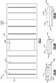
- FIG. 1 shows a control module 20 including a motherboard 22 and a plurality of removable circuit boards 24.
- the module 20 communicates control signals to and from a use, such as a system on an aircraft.
- Boards 24 may be LRMs, but other board types may be used. As known, the boards are electrically connected to the motherboard.
- An outer housing 26 surrounds the boards 22 and 24. Of course, this view is highly schematic.
- circuit boards 24 on the motherboard 22 it would be desirable to be able to freely replace the circuit boards 24 on the motherboard 22 to achieve tailored control features for a particular system. Also, some replacement may be required for maintenance purposes. In addition, it is desirable to provide cooling for elements on the circuit boards 24. This becomes particularly valuable if the circuit boards are power distribution circuits carrying power transistors.
- FIG. 2 shows a circuit board embodiment 24.
- control circuits or switches 28 communicate with transistors in an enclosure 30.
- the enclosures 30 each surround an individual power transistor or group of power transistors and/or other components that can benefit from additional cooling.
- the board 24 has connections to be secured to motherboard 22.
- Figure 3A shows a first embodiment wherein a power transistor 32 is mounted within the enclosure 30.
- Internal chamber 34 is filled with a dielectric cooling fluid. As shown by the curved line, fluid flowing adjacent to the power transistor 32 is heated and flows away, towards the enclosure wall, where it may dissipate heat to the outer environment.
- the fluid may boil as result of absorbing the heat, increasing the pressure and assisting heat transfer.
- the pressure relief valve may simply vent the fluid to the environment.
- Figure 3B shows an embodiment 130 wherein a power transistor 132 is placed within a chamber 134.
- the outer housing is shown to be flexible at 136.
- a nominal position is shown in phantom at 138. As the fluid with chamber 134 expands, it can force the enclosure to the expanded position 136. Again, this will allow the enclosure 130 to facilitate expansion of the fluid as it heats.
- FIG. 3C Another embodiment 230 is shown in Figure 3C .
- a power transistor 232 is placed within a chamber 234. Within chamber 234, there is a liquid cooling fluid level 236 and a compressible gas level 238. As the fluid 236 expands, it can compress the gas 238 allowing expansion of the fluid.
- Figure 3C embodiment may be used in conjunction with a flexible housing such as shown in Figure 3B .
- a flexible housing such as shown in Figure 3B .
- This is shown schematically, as the housing moves from a nominal position 240 to an expanded position 242.
- switches work with the transistors 32/132/232 to communicate signals to a use, typically through the motherboard.
- individual line removable modules 24 may be removed from a control module 20 without the complexity of removing the cooling liquid from the enclosure. Also, with these embodiments, individual transistors or groups of transistors, and the associated enclosures, may be removed from the circuit board 24 for replacement or repair.
- Figure 4 shows another embodiment 300 wherein an entire circuit board 24 is placed within an enclosed immersion cooling housing or enclosure 302.
- Housing 302 may be provided with heat transfer surfaces on its outer periphery, such as roughened surface or provided with other heat transfer enhancing features such as fins, etc.
- the enclosure is filled with dielectric cooling fluid and the expansion features of Figures 3A, 3B, and 3C may be applied to the entire housing.
- appropriate electrical connection shown at 303 extends outwardly of the enclosure.
- FIG 5 shows a control module 310 having a motherboard 22, a plurality of removable circuit boards 124, which are not provided with immersion cooling, and an enclosed circuit board 300 as shown in Figure 4 .
- the module 310 communicates with a use.
- the enclosed circuit board 300 is illustrated in Figure 6A , wherein the board 513 is received within a fluid 515, with a pressure relief valve 312 leading to a holding container 314, and an inlet 316.
- This embodiment will operate to allow expansion of the fluid, and movement of the fluid outwardly of the enclosure should it exceed a predetermined pressure. As such, it operates similar to the Figure 3A embodiment.
- Figure 6B shows an enclosed circuit board 410, which may replace the enclosed board 300 of Figure 5 , wherein the board 517 is received within a fluid 519, in which an enclosure has a nominal wall location 412, but is flexible such that it can expand as shown at 414 to accommodate expansion of the liquid within the enclosure. As such, it functions like the Figure 3B embodiment.
- Figure 6C shows an enclosure 510, wherein the board 512 itself is received within a fluid 514.
- the fluid is a liquid.
- a layer of compressible gas 516 is also included. As the liquid 514 expands, it can compress the gas layer 516.
- the enclosure 518 may optionally have a flexible wall such that it can expand as shown at 520. As such, this is similar to the Figure 3C embodiment.
- a control module 20, 310 has a motherboard 22 and a plurality of removable circuit boards 24/124/300. At least one of the circuit boards is provided with immersion cooling of an electronic component surrounded by an enclosure that does not enclose others of the plurality of circuit boards.
- a circuit board 24/300 has a plurality of electronic components, with an immersion cooling fluid within an enclosure 30/302, such that the circuit board and enclosure can be removed or inserted as a unit into a motherboard without releasing the fluid from the enclosure.
- Providing the enclosed cooling facilitates the specific tailoring of the circuit boards 24 or 300. Further, this arrangement facilitates the replacement or repair of individual line removable modules or circuits.
- the assembly can facilitate the tailoring of a combination of boards.
- a system would have a number of different module/board types such as a power supply, microprocessor, discrete I/O communications, and SSPC modules.
- module/board types such as a power supply, microprocessor, discrete I/O communications, and SSPC modules.
- SSPC modules As different customers have different numbers and types of loads to be controlled, a mix of modules can be tailored to particular needs. For example, one customer may need several low current DC SSPCs while another might need a mix of AC and DC of various load currents.
Landscapes
- Engineering & Computer Science (AREA)
- Microelectronics & Electronic Packaging (AREA)
- Physics & Mathematics (AREA)
- Thermal Sciences (AREA)
- Cooling Or The Like Of Electrical Apparatus (AREA)
Abstract
Description
- This application relates to immersion cooling of power electronic circuits.
- Modem systems are becoming more and more complex and, as a result, complex electrical controls are provided for many such systems. One example system would be aerospace equipment, such as an aircraft.
- Control modules for such system often include a motherboard and a plurality of line removable modules ("LRMs") or other circuit boards. One particular type of LRM carries a number of power transistors forming solid state power controllers ("SSPC"). Power transistors have unique cooling challenges.
- One known type of power transistors is a metal oxide field effect transistor ("MOSFET"). Although MOSFETs are mentioned, other types of solid state power controllers also raise similar challenges.
- Modem control modules may include a very high number of such transistors and electronic controls. The heat generated by these transistors raises challenges with cooling.
- Solid state power controllers are subject to transient heat loss due to a number of reasons, including load in-rush currents, fly back when inductive load currents are braked, lightning strikes, overcurrent faults that must be carried for a short period of time prior to turning the SSPC off, etc.
- In general, fluid immersion cooling for control circuits have surrounded the entire control module. This raises challenges, as a designer of modem control modules would like to be able to tailor a particular combination of motherboard and circuit boards. Further, when the entire control module is surrounded by cooling fluid, it is difficult to replace any one LRM. Fluid cooling circuits typically include a hermetic seal and, thus, are not prone to easy repair.
- A cooling arrangement has a circuit board and a plurality of electronic components in operable communication with the circuit board. An enclosure is attached to the circuit board being configured to retain a fluid around at least one of the plurality of electronic components. The circuit board with the enclosure is attached thereto being removably connectable to a motherboard.
- These and other features may be best understood from the following drawings and specification.
-
-
Figure 1 shows an example control module. -
Figure 2 shows a circuit board within theFigure 1 control module. -
Figure 3A shows a first embodiment of an optional feature. -
Figure 3B shows a second embodiment. -
Figure 3C shows a third embodiment. -
Figure 4 shows an alternative circuit board. -
Figure 5 shows a control module utilizing theFigure 4 embodiment. -
Figure 6A shows an optional feature. -
Figure 6B shows another embodiment. -
Figure 6C shows yet another embodiment. -
Figure 1 shows acontrol module 20 including amotherboard 22 and a plurality ofremovable circuit boards 24. Themodule 20 communicates control signals to and from a use, such as a system on an aircraft.Boards 24 may be LRMs, but other board types may be used. As known, the boards are electrically connected to the motherboard. Anouter housing 26 surrounds theboards - As mentioned above, it would be desirable to be able to freely replace the
circuit boards 24 on themotherboard 22 to achieve tailored control features for a particular system. Also, some replacement may be required for maintenance purposes. In addition, it is desirable to provide cooling for elements on thecircuit boards 24. This becomes particularly valuable if the circuit boards are power distribution circuits carrying power transistors. -
Figure 2 shows acircuit board embodiment 24. As shown, control circuits orswitches 28 communicate with transistors in anenclosure 30. Theenclosures 30 each surround an individual power transistor or group of power transistors and/or other components that can benefit from additional cooling. In an embodiment theboard 24 has connections to be secured tomotherboard 22. -
Figure 3A shows a first embodiment wherein apower transistor 32 is mounted within theenclosure 30.Internal chamber 34 is filled with a dielectric cooling fluid. As shown by the curved line, fluid flowing adjacent to thepower transistor 32 is heated and flows away, towards the enclosure wall, where it may dissipate heat to the outer environment. - As mentioned above, much of the heat generated by the
transistor 32 may be transient. As the fluid absorbs this heat, the fluid expands such that the pressure within thechamber 34 rises.Pressure relief valve 36 may allow fluid to then flow outward of the enclosure. Aholding container 38 is shown schematically along with areturn inlet 40. Once the fluid withinchamber 34 cools, the fluid may return fromholding chamber 38 intoinlet 40. In this manner, theenclosure 30 facilitates handling an expanding fluid. In some embodiments the fluid may boil as result of absorbing the heat, increasing the pressure and assisting heat transfer. - As an alternative, the pressure relief valve may simply vent the fluid to the environment.
-
Figure 3B shows anembodiment 130 wherein apower transistor 132 is placed within achamber 134. The outer housing is shown to be flexible at 136. A nominal position is shown in phantom at 138. As the fluid withchamber 134 expands, it can force the enclosure to the expandedposition 136. Again, this will allow theenclosure 130 to facilitate expansion of the fluid as it heats. - Another
embodiment 230 is shown inFigure 3C . Apower transistor 232 is placed within achamber 234. Withinchamber 234, there is a liquidcooling fluid level 236 and acompressible gas level 238. As the fluid 236 expands, it can compress thegas 238 allowing expansion of the fluid. - Notably, the
Figure 3C embodiment may be used in conjunction with a flexible housing such as shown inFigure 3B . This is shown schematically, as the housing moves from anominal position 240 to an expandedposition 242. - As shown in each of
Figures 3A-3C , switches work with thetransistors 32/132/232 to communicate signals to a use, typically through the motherboard. - With these embodiments, individual line
removable modules 24 may be removed from acontrol module 20 without the complexity of removing the cooling liquid from the enclosure. Also, with these embodiments, individual transistors or groups of transistors, and the associated enclosures, may be removed from thecircuit board 24 for replacement or repair. -
Figure 4 shows anotherembodiment 300 wherein anentire circuit board 24 is placed within an enclosed immersion cooling housing orenclosure 302.Housing 302 may be provided with heat transfer surfaces on its outer periphery, such as roughened surface or provided with other heat transfer enhancing features such as fins, etc. The enclosure is filled with dielectric cooling fluid and the expansion features ofFigures 3A, 3B, and 3C may be applied to the entire housing. Of course, appropriate electrical connection shown at 303 extends outwardly of the enclosure. -
Figure 5 shows acontrol module 310 having amotherboard 22, a plurality ofremovable circuit boards 124, which are not provided with immersion cooling, and anenclosed circuit board 300 as shown inFigure 4 . Again, themodule 310 communicates with a use. - The
enclosed circuit board 300 is illustrated inFigure 6A , wherein theboard 513 is received within afluid 515, with apressure relief valve 312 leading to a holdingcontainer 314, and aninlet 316. This embodiment will operate to allow expansion of the fluid, and movement of the fluid outwardly of the enclosure should it exceed a predetermined pressure. As such, it operates similar to theFigure 3A embodiment. -
Figure 6B shows anenclosed circuit board 410, which may replace theenclosed board 300 ofFigure 5 , wherein theboard 517 is received within afluid 519, in which an enclosure has a nominal wall location 412, but is flexible such that it can expand as shown at 414 to accommodate expansion of the liquid within the enclosure. As such, it functions like theFigure 3B embodiment. -
Figure 6C shows anenclosure 510, wherein theboard 512 itself is received within afluid 514. The fluid is a liquid. A layer ofcompressible gas 516 is also included. As the liquid 514 expands, it can compress thegas layer 516. In addition, theenclosure 518 may optionally have a flexible wall such that it can expand as shown at 520. As such, this is similar to theFigure 3C embodiment. - In sum, a
control module motherboard 22 and a plurality ofremovable circuit boards 24/124/300. At least one of the circuit boards is provided with immersion cooling of an electronic component surrounded by an enclosure that does not enclose others of the plurality of circuit boards. - In embodiments, a
circuit board 24/300 has a plurality of electronic components, with an immersion cooling fluid within anenclosure 30/302, such that the circuit board and enclosure can be removed or inserted as a unit into a motherboard without releasing the fluid from the enclosure. - Providing the enclosed cooling facilitates the specific tailoring of the
circuit boards - The assembly can facilitate the tailoring of a combination of boards. Typically, a system would have a number of different module/board types such as a power supply, microprocessor, discrete I/O communications, and SSPC modules. As different customers have different numbers and types of loads to be controlled, a mix of modules can be tailored to particular needs. For example, one customer may need several low current DC SSPCs while another might need a mix of AC and DC of various load currents.
- It is desirable to be able to have high loss boards (high current especially AC) be specially cooled while the rest of the system be traditional boards. This disclosure achieves such a goal.
- Although an embodiment of this invention has been disclosed, a worker of ordinary skill in this art would recognize that certain modifications would come within the scope of this invention. For that reason, the following claims should be studied to determine the true scope and content of this invention.
Claims (13)
- A cooling arrangement comprising:a circuit board (24; 124; 300; 410; 512; 513; 517);a plurality of electronic components (32; 132; 232) in operable communication with the circuit board (24; 124; 300; 410; 512; 513; 517); andan enclosure (30; 134; 234; 518) attached to the circuit board (24; 124; 300; 410; 512; 513; 517) being configured to retain a fluid around at least one of the plurality of electronic components (32; 132; 232), said circuit board (24; 124; 300; 410; 512; 513; 517) with the enclosure (30; 134; 234; 518) attached thereto being removably connectable to a motherboard (22).
- The cooling arrangement as set forth in claim 1, wherein said plurality of said electronic components (32; 132; 232) includes at least one power transistor (32; 132; 232) and at least one control circuit, and said enclosure (30; 134; 234; 518) enclosing said at least one power transistor (32; 132; 232), said at least one control circuit being outside said enclosure (30; 134; 234; 518).
- The cooling arrangement as set forth in claim 2, wherein there are a plurality of said transistors (32; 132; 232) and a plurality of enclosures (30; 134; 234; 518) each enclosing one of said plurality of transistors (32; 132; 232), with a plurality of control circuits positioned outside of said plurality of enclosures (30; 134; 234; 518).
- The cooling arrangement as set forth in claim 1, wherein said plurality of electronic components (32; 132; 232) includes a transistor (32; 132; 232) and a control circuit received within said enclosure.
- A control module comprising:a motherboard (22) and a plurality of removable circuit boards (24; 124; 300; 410; 512; 513; 517), and at least one of said circuit boards (24; 124; 300; 410; 512; 513; 517) being provided with immersion cooling of an electronic component (32; 132; 232) surrounded by an enclosure (30; 134; 234; 518) that does not enclose others of said plurality of circuit boards (30; 134; 234; 518).
- The control module as set forth in claim 5, wherein said at least one of said circuit boards (24; 124; 300; 410; 512; 513; 517) has at least one power transistor (32; 132; 232) and at least one control circuit, and said enclosure (30; 134; 234; 518) enclosing said at least one power transistor (32; 132; 232), said at least one control circuit being outside said enclosure.
- The control module as set forth in claim 6, wherein there are a plurality of said transistors (32; 132; 232) and a plurality of enclosures (30; 134; 234; 518) each enclosing one of said plurality of transistors (32; 132; 232), with a plurality of control circuits positioned outside of said plurality of enclosures.
- The control module as set forth in claim 5, wherein said at least one of said circuit boards (24; 124; 300; 410; 512; 513; 517) is enclosed entirely in said enclosure (30;134; 234; 518) and at least one circuit (24; 124; 300; 410; 512; 513; 517) board including a transistor (32; 132; 232) and a control circuit all received within said enclosure (30; 134; 234; 518), with others of said plurality of circuit boards being outside said enclosure.
- The cooling arrangement or control module as set forth in any preceding claim, wherein said enclosure (134; 234; 518) is provided with a feature to allow expansion of a fluid within said enclosure (134; 234; 518).
- The cooling arrangement or control module as set forth in claim 9, wherein a pressure relief valve (36; 312) allows fluid to move outwardly of a chamber surrounding said transistor (32; 513).
- The cooling arrangement or control module as set forth in claim 9, wherein said enclosure (130; 230; 518) includes at least one flexible wall, said wall can expand to accommodate an increase in volume of said fluid.
- The cooling arrangement or control module as set forth in claim 9, wherein said fluid is a liquid (236; 514) and said enclosure is also provided with a compressible gas (238; 516), with said compressible gas allowing expansion of said liquid (236; 514).
- The cooling arrangement or control module as set forth in claim 11, wherein said fluid is a liquid (236; 514) and said enclosure is also provided with a compressible gas (238; 516), with said compressible gas allowing expansion of said liquid (236; 514).
Applications Claiming Priority (1)
| Application Number | Priority Date | Filing Date | Title |
|---|---|---|---|
| US14/996,472 US20170208705A1 (en) | 2016-01-15 | 2016-01-15 | Immersion cooling of power circuit |
Publications (2)
| Publication Number | Publication Date |
|---|---|
| EP3193572A1 true EP3193572A1 (en) | 2017-07-19 |
| EP3193572B1 EP3193572B1 (en) | 2023-03-22 |
Family
ID=57796277
Family Applications (1)
| Application Number | Title | Priority Date | Filing Date |
|---|---|---|---|
| EP17151516.6A Active EP3193572B1 (en) | 2016-01-15 | 2017-01-13 | Immersion cooling of power circuit |
Country Status (2)
| Country | Link |
|---|---|
| US (1) | US20170208705A1 (en) |
| EP (1) | EP3193572B1 (en) |
Families Citing this family (7)
| Publication number | Priority date | Publication date | Assignee | Title |
|---|---|---|---|---|
| GB201619987D0 (en) | 2016-11-25 | 2017-01-11 | Iceotope Ltd | Fluid cooling system |
| US20190191589A1 (en) * | 2017-12-15 | 2019-06-20 | Google Llc | Three-Dimensional Electronic Structure with Integrated Phase-Change Cooling |
| US10609839B1 (en) * | 2018-09-28 | 2020-03-31 | Liquidcool Solutions, Inc. | Liquid submersion cooled electronic systems and devices |
| CN111295075B (en) * | 2018-12-07 | 2023-08-25 | 上海航空电器有限公司 | Immersion cooling structure for SSPC |
| US11917793B2 (en) | 2021-01-11 | 2024-02-27 | Cisco Technology, Inc. | Localized immersion cooling enclosure |
| US11647607B2 (en) | 2021-01-22 | 2023-05-09 | Cisco Technology, Inc. | Localized immersion cooling enclosure with thermal efficiency features |
| CN116027188B (en) * | 2022-12-30 | 2025-06-06 | 北京航空航天大学 | A method and system for detecting transient protection characteristics of a solid-state power control device |
Citations (2)
| Publication number | Priority date | Publication date | Assignee | Title |
|---|---|---|---|---|
| US20070034360A1 (en) * | 2005-06-08 | 2007-02-15 | Hall Jack P | High performance cooling assembly for electronics |
| US20080116568A1 (en) * | 2006-11-21 | 2008-05-22 | The Boeing Company | Direct semiconductor contact ebullient cooling package |
Family Cites Families (5)
| Publication number | Priority date | Publication date | Assignee | Title |
|---|---|---|---|---|
| US3851221A (en) * | 1972-11-30 | 1974-11-26 | P Beaulieu | Integrated circuit package |
| JPS61253843A (en) * | 1985-05-07 | 1986-11-11 | Hitachi Ltd | Semiconductor device |
| US5305184A (en) * | 1992-12-16 | 1994-04-19 | Ibm Corporation | Method and apparatus for immersion cooling or an electronic board |
| US7150109B2 (en) * | 2003-08-25 | 2006-12-19 | Isothermal Systems Research, Inc. | Dry-wet thermal management system |
| US20100319902A1 (en) * | 2009-06-19 | 2010-12-23 | Wan Ching Chou | Auxiliary apparatus for vehicle water tank |
-
2016
- 2016-01-15 US US14/996,472 patent/US20170208705A1/en not_active Abandoned
-
2017
- 2017-01-13 EP EP17151516.6A patent/EP3193572B1/en active Active
Patent Citations (2)
| Publication number | Priority date | Publication date | Assignee | Title |
|---|---|---|---|---|
| US20070034360A1 (en) * | 2005-06-08 | 2007-02-15 | Hall Jack P | High performance cooling assembly for electronics |
| US20080116568A1 (en) * | 2006-11-21 | 2008-05-22 | The Boeing Company | Direct semiconductor contact ebullient cooling package |
Also Published As
| Publication number | Publication date |
|---|---|
| EP3193572B1 (en) | 2023-03-22 |
| US20170208705A1 (en) | 2017-07-20 |
Similar Documents
| Publication | Publication Date | Title |
|---|---|---|
| EP3193572B1 (en) | Immersion cooling of power circuit | |
| CN109631225B (en) | Air conditioner heat dissipation control method and device, air conditioner and storage medium | |
| WO2004042307A3 (en) | Methods and apparatuses for electronics cooling | |
| EP2744316A2 (en) | Power electronics device and its cooling arrangement | |
| EP2734022A2 (en) | Cooling system | |
| WO2016053323A1 (en) | Modular utilities | |
| WO2021058062A3 (en) | Electrical enclosure assembly with at least one it rack or electrical enclosure housing and with at least one cooling device, and corresponding method | |
| EP2928276B1 (en) | Cooling flow optimization | |
| CN107432100A (en) | Cooling devices for air conditioning of switchgear | |
| EP2706632A2 (en) | Restricted breathing enclosure | |
| CN116833529A (en) | Soldering system with potted circuit board and method of manufacturing the same | |
| CN108206128A (en) | Anti-condensation method and device for power semiconductor device | |
| CN103227424A (en) | Cooled electric assembly | |
| CN208889580U (en) | A kind of contactless relay | |
| CN110636741A (en) | Device having a housing and power electronics arranged therein on the bottom of the housing | |
| US20070134365A1 (en) | Water-cooled control device for a plastics processing machine | |
| US6713898B2 (en) | Internal reactor thyristor stack | |
| KR20120104118A (en) | Method for thermal management of an electric power conversion installation and installation for implementing the method | |
| US9692318B2 (en) | Synchronous rectifier, use of such a synchronous rectifier in a switching power supply, as well as a switching power supply | |
| JP5697713B2 (en) | Power converter and control method thereof | |
| CN106199092B (en) | A kind of combined high-power electronic load device | |
| EP2618645A1 (en) | Thermal management of electronics and photonics equipment | |
| EP4459851A1 (en) | Electric motor with heat dissipation system | |
| US10637216B2 (en) | Power control system with improved thermal performance | |
| CN211929930U (en) | A cooling device for preventing overheating in use of a power distribution cabinet |
Legal Events
| Date | Code | Title | Description |
|---|---|---|---|
| PUAI | Public reference made under article 153(3) epc to a published international application that has entered the european phase |
Free format text: ORIGINAL CODE: 0009012 |
|
| STAA | Information on the status of an ep patent application or granted ep patent |
Free format text: STATUS: THE APPLICATION HAS BEEN PUBLISHED |
|
| AK | Designated contracting states |
Kind code of ref document: A1 Designated state(s): AL AT BE BG CH CY CZ DE DK EE ES FI FR GB GR HR HU IE IS IT LI LT LU LV MC MK MT NL NO PL PT RO RS SE SI SK SM TR |
|
| AX | Request for extension of the european patent |
Extension state: BA ME |
|
| STAA | Information on the status of an ep patent application or granted ep patent |
Free format text: STATUS: REQUEST FOR EXAMINATION WAS MADE |
|
| 17P | Request for examination filed |
Effective date: 20180119 |
|
| RBV | Designated contracting states (corrected) |
Designated state(s): AL AT BE BG CH CY CZ DE DK EE ES FI FR GB GR HR HU IE IS IT LI LT LU LV MC MK MT NL NO PL PT RO RS SE SI SK SM TR |
|
| STAA | Information on the status of an ep patent application or granted ep patent |
Free format text: STATUS: EXAMINATION IS IN PROGRESS |
|
| 17Q | First examination report despatched |
Effective date: 20200928 |
|
| GRAP | Despatch of communication of intention to grant a patent |
Free format text: ORIGINAL CODE: EPIDOSNIGR1 |
|
| STAA | Information on the status of an ep patent application or granted ep patent |
Free format text: STATUS: GRANT OF PATENT IS INTENDED |
|
| INTG | Intention to grant announced |
Effective date: 20221007 |
|
| GRAS | Grant fee paid |
Free format text: ORIGINAL CODE: EPIDOSNIGR3 |
|
| GRAA | (expected) grant |
Free format text: ORIGINAL CODE: 0009210 |
|
| STAA | Information on the status of an ep patent application or granted ep patent |
Free format text: STATUS: THE PATENT HAS BEEN GRANTED |
|
| AK | Designated contracting states |
Kind code of ref document: B1 Designated state(s): AL AT BE BG CH CY CZ DE DK EE ES FI FR GB GR HR HU IE IS IT LI LT LU LV MC MK MT NL NO PL PT RO RS SE SI SK SM TR |
|
| REG | Reference to a national code |
Ref country code: GB Ref legal event code: FG4D |
|
| REG | Reference to a national code |
Ref country code: CH Ref legal event code: EP |
|
| REG | Reference to a national code |
Ref country code: DE Ref legal event code: R096 Ref document number: 602017066951 Country of ref document: DE |
|
| REG | Reference to a national code |
Ref country code: IE Ref legal event code: FG4D |
|
| REG | Reference to a national code |
Ref country code: AT Ref legal event code: REF Ref document number: 1556038 Country of ref document: AT Kind code of ref document: T Effective date: 20230415 |
|
| P01 | Opt-out of the competence of the unified patent court (upc) registered |
Effective date: 20230522 |
|
| REG | Reference to a national code |
Ref country code: LT Ref legal event code: MG9D |
|
| REG | Reference to a national code |
Ref country code: NL Ref legal event code: MP Effective date: 20230322 |
|
| PG25 | Lapsed in a contracting state [announced via postgrant information from national office to epo] |
Ref country code: RS Free format text: LAPSE BECAUSE OF FAILURE TO SUBMIT A TRANSLATION OF THE DESCRIPTION OR TO PAY THE FEE WITHIN THE PRESCRIBED TIME-LIMIT Effective date: 20230322 Ref country code: NO Free format text: LAPSE BECAUSE OF FAILURE TO SUBMIT A TRANSLATION OF THE DESCRIPTION OR TO PAY THE FEE WITHIN THE PRESCRIBED TIME-LIMIT Effective date: 20230622 Ref country code: LV Free format text: LAPSE BECAUSE OF FAILURE TO SUBMIT A TRANSLATION OF THE DESCRIPTION OR TO PAY THE FEE WITHIN THE PRESCRIBED TIME-LIMIT Effective date: 20230322 Ref country code: LT Free format text: LAPSE BECAUSE OF FAILURE TO SUBMIT A TRANSLATION OF THE DESCRIPTION OR TO PAY THE FEE WITHIN THE PRESCRIBED TIME-LIMIT Effective date: 20230322 Ref country code: HR Free format text: LAPSE BECAUSE OF FAILURE TO SUBMIT A TRANSLATION OF THE DESCRIPTION OR TO PAY THE FEE WITHIN THE PRESCRIBED TIME-LIMIT Effective date: 20230322 |
|
| REG | Reference to a national code |
Ref country code: AT Ref legal event code: MK05 Ref document number: 1556038 Country of ref document: AT Kind code of ref document: T Effective date: 20230322 |
|
| PG25 | Lapsed in a contracting state [announced via postgrant information from national office to epo] |
Ref country code: SE Free format text: LAPSE BECAUSE OF FAILURE TO SUBMIT A TRANSLATION OF THE DESCRIPTION OR TO PAY THE FEE WITHIN THE PRESCRIBED TIME-LIMIT Effective date: 20230322 Ref country code: NL Free format text: LAPSE BECAUSE OF FAILURE TO SUBMIT A TRANSLATION OF THE DESCRIPTION OR TO PAY THE FEE WITHIN THE PRESCRIBED TIME-LIMIT Effective date: 20230322 Ref country code: GR Free format text: LAPSE BECAUSE OF FAILURE TO SUBMIT A TRANSLATION OF THE DESCRIPTION OR TO PAY THE FEE WITHIN THE PRESCRIBED TIME-LIMIT Effective date: 20230623 Ref country code: FI Free format text: LAPSE BECAUSE OF FAILURE TO SUBMIT A TRANSLATION OF THE DESCRIPTION OR TO PAY THE FEE WITHIN THE PRESCRIBED TIME-LIMIT Effective date: 20230322 |
|
| PG25 | Lapsed in a contracting state [announced via postgrant information from national office to epo] |
Ref country code: SM Free format text: LAPSE BECAUSE OF FAILURE TO SUBMIT A TRANSLATION OF THE DESCRIPTION OR TO PAY THE FEE WITHIN THE PRESCRIBED TIME-LIMIT Effective date: 20230322 Ref country code: RO Free format text: LAPSE BECAUSE OF FAILURE TO SUBMIT A TRANSLATION OF THE DESCRIPTION OR TO PAY THE FEE WITHIN THE PRESCRIBED TIME-LIMIT Effective date: 20230322 Ref country code: PT Free format text: LAPSE BECAUSE OF FAILURE TO SUBMIT A TRANSLATION OF THE DESCRIPTION OR TO PAY THE FEE WITHIN THE PRESCRIBED TIME-LIMIT Effective date: 20230724 Ref country code: ES Free format text: LAPSE BECAUSE OF FAILURE TO SUBMIT A TRANSLATION OF THE DESCRIPTION OR TO PAY THE FEE WITHIN THE PRESCRIBED TIME-LIMIT Effective date: 20230322 Ref country code: EE Free format text: LAPSE BECAUSE OF FAILURE TO SUBMIT A TRANSLATION OF THE DESCRIPTION OR TO PAY THE FEE WITHIN THE PRESCRIBED TIME-LIMIT Effective date: 20230322 Ref country code: AT Free format text: LAPSE BECAUSE OF FAILURE TO SUBMIT A TRANSLATION OF THE DESCRIPTION OR TO PAY THE FEE WITHIN THE PRESCRIBED TIME-LIMIT Effective date: 20230322 |
|
| PG25 | Lapsed in a contracting state [announced via postgrant information from national office to epo] |
Ref country code: SK Free format text: LAPSE BECAUSE OF FAILURE TO SUBMIT A TRANSLATION OF THE DESCRIPTION OR TO PAY THE FEE WITHIN THE PRESCRIBED TIME-LIMIT Effective date: 20230322 Ref country code: PL Free format text: LAPSE BECAUSE OF FAILURE TO SUBMIT A TRANSLATION OF THE DESCRIPTION OR TO PAY THE FEE WITHIN THE PRESCRIBED TIME-LIMIT Effective date: 20230322 Ref country code: IS Free format text: LAPSE BECAUSE OF FAILURE TO SUBMIT A TRANSLATION OF THE DESCRIPTION OR TO PAY THE FEE WITHIN THE PRESCRIBED TIME-LIMIT Effective date: 20230722 |
|
| REG | Reference to a national code |
Ref country code: DE Ref legal event code: R097 Ref document number: 602017066951 Country of ref document: DE |
|
| PLBE | No opposition filed within time limit |
Free format text: ORIGINAL CODE: 0009261 |
|
| STAA | Information on the status of an ep patent application or granted ep patent |
Free format text: STATUS: NO OPPOSITION FILED WITHIN TIME LIMIT |
|
| PG25 | Lapsed in a contracting state [announced via postgrant information from national office to epo] |
Ref country code: SI Free format text: LAPSE BECAUSE OF FAILURE TO SUBMIT A TRANSLATION OF THE DESCRIPTION OR TO PAY THE FEE WITHIN THE PRESCRIBED TIME-LIMIT Effective date: 20230322 Ref country code: DK Free format text: LAPSE BECAUSE OF FAILURE TO SUBMIT A TRANSLATION OF THE DESCRIPTION OR TO PAY THE FEE WITHIN THE PRESCRIBED TIME-LIMIT Effective date: 20230322 Ref country code: CZ Free format text: LAPSE BECAUSE OF FAILURE TO SUBMIT A TRANSLATION OF THE DESCRIPTION OR TO PAY THE FEE WITHIN THE PRESCRIBED TIME-LIMIT Effective date: 20230322 |
|
| 26N | No opposition filed |
Effective date: 20240102 |
|
| PG25 | Lapsed in a contracting state [announced via postgrant information from national office to epo] |
Ref country code: IT Free format text: LAPSE BECAUSE OF FAILURE TO SUBMIT A TRANSLATION OF THE DESCRIPTION OR TO PAY THE FEE WITHIN THE PRESCRIBED TIME-LIMIT Effective date: 20230322 |
|
| PG25 | Lapsed in a contracting state [announced via postgrant information from national office to epo] |
Ref country code: MC Free format text: LAPSE BECAUSE OF FAILURE TO SUBMIT A TRANSLATION OF THE DESCRIPTION OR TO PAY THE FEE WITHIN THE PRESCRIBED TIME-LIMIT Effective date: 20230322 |
|
| PG25 | Lapsed in a contracting state [announced via postgrant information from national office to epo] |
Ref country code: MC Free format text: LAPSE BECAUSE OF FAILURE TO SUBMIT A TRANSLATION OF THE DESCRIPTION OR TO PAY THE FEE WITHIN THE PRESCRIBED TIME-LIMIT Effective date: 20230322 |
|
| REG | Reference to a national code |
Ref country code: CH Ref legal event code: PL |
|
| PG25 | Lapsed in a contracting state [announced via postgrant information from national office to epo] |
Ref country code: LU Free format text: LAPSE BECAUSE OF NON-PAYMENT OF DUE FEES Effective date: 20240113 |
|
| PG25 | Lapsed in a contracting state [announced via postgrant information from national office to epo] |
Ref country code: LU Free format text: LAPSE BECAUSE OF NON-PAYMENT OF DUE FEES Effective date: 20240113 |
|
| PG25 | Lapsed in a contracting state [announced via postgrant information from national office to epo] |
Ref country code: BE Free format text: LAPSE BECAUSE OF NON-PAYMENT OF DUE FEES Effective date: 20240131 |
|
| PG25 | Lapsed in a contracting state [announced via postgrant information from national office to epo] |
Ref country code: CH Free format text: LAPSE BECAUSE OF NON-PAYMENT OF DUE FEES Effective date: 20240131 |
|
| PG25 | Lapsed in a contracting state [announced via postgrant information from national office to epo] |
Ref country code: CH Free format text: LAPSE BECAUSE OF NON-PAYMENT OF DUE FEES Effective date: 20240131 Ref country code: BE Free format text: LAPSE BECAUSE OF NON-PAYMENT OF DUE FEES Effective date: 20240131 |
|
| REG | Reference to a national code |
Ref country code: BE Ref legal event code: MM Effective date: 20240131 |
|
| PG25 | Lapsed in a contracting state [announced via postgrant information from national office to epo] |
Ref country code: BG Free format text: LAPSE BECAUSE OF FAILURE TO SUBMIT A TRANSLATION OF THE DESCRIPTION OR TO PAY THE FEE WITHIN THE PRESCRIBED TIME-LIMIT Effective date: 20230322 |
|
| PG25 | Lapsed in a contracting state [announced via postgrant information from national office to epo] |
Ref country code: BG Free format text: LAPSE BECAUSE OF FAILURE TO SUBMIT A TRANSLATION OF THE DESCRIPTION OR TO PAY THE FEE WITHIN THE PRESCRIBED TIME-LIMIT Effective date: 20230322 |
|
| PGFP | Annual fee paid to national office [announced via postgrant information from national office to epo] |
Ref country code: GB Payment date: 20241219 Year of fee payment: 9 |
|
| PGFP | Annual fee paid to national office [announced via postgrant information from national office to epo] |
Ref country code: FR Payment date: 20241220 Year of fee payment: 9 |
|
| PG25 | Lapsed in a contracting state [announced via postgrant information from national office to epo] |
Ref country code: IE Free format text: LAPSE BECAUSE OF NON-PAYMENT OF DUE FEES Effective date: 20240113 |
|
| PG25 | Lapsed in a contracting state [announced via postgrant information from national office to epo] |
Ref country code: IE Free format text: LAPSE BECAUSE OF NON-PAYMENT OF DUE FEES Effective date: 20240113 |
|
| PGFP | Annual fee paid to national office [announced via postgrant information from national office to epo] |
Ref country code: DE Payment date: 20241218 Year of fee payment: 9 |
|
| PG25 | Lapsed in a contracting state [announced via postgrant information from national office to epo] |
Ref country code: CY Free format text: LAPSE BECAUSE OF FAILURE TO SUBMIT A TRANSLATION OF THE DESCRIPTION OR TO PAY THE FEE WITHIN THE PRESCRIBED TIME-LIMIT; INVALID AB INITIO Effective date: 20170113 |
|
| PG25 | Lapsed in a contracting state [announced via postgrant information from national office to epo] |
Ref country code: HU Free format text: LAPSE BECAUSE OF FAILURE TO SUBMIT A TRANSLATION OF THE DESCRIPTION OR TO PAY THE FEE WITHIN THE PRESCRIBED TIME-LIMIT; INVALID AB INITIO Effective date: 20170113 |
|
| PG25 | Lapsed in a contracting state [announced via postgrant information from national office to epo] |
Ref country code: TR Free format text: LAPSE BECAUSE OF FAILURE TO SUBMIT A TRANSLATION OF THE DESCRIPTION OR TO PAY THE FEE WITHIN THE PRESCRIBED TIME-LIMIT Effective date: 20230322 |