EP3193002A1 - Inverseur de poussée à cascade translatable et porte de blocage escamotée - Google Patents
Inverseur de poussée à cascade translatable et porte de blocage escamotée Download PDFInfo
- Publication number
- EP3193002A1 EP3193002A1 EP17151250.2A EP17151250A EP3193002A1 EP 3193002 A1 EP3193002 A1 EP 3193002A1 EP 17151250 A EP17151250 A EP 17151250A EP 3193002 A1 EP3193002 A1 EP 3193002A1
- Authority
- EP
- European Patent Office
- Prior art keywords
- thrust reverser
- blocker door
- sleeve
- coupled
- deployment
- Prior art date
- Legal status (The legal status is an assumption and is not a legal conclusion. Google has not performed a legal analysis and makes no representation as to the accuracy of the status listed.)
- Granted
Links
- 230000007246 mechanism Effects 0.000 claims description 18
- 238000013519 translation Methods 0.000 claims description 7
- 230000008859 change Effects 0.000 claims description 3
- 230000006835 compression Effects 0.000 claims description 3
- 238000007906 compression Methods 0.000 claims description 3
- 230000036316 preload Effects 0.000 claims description 3
- 238000010276 construction Methods 0.000 description 2
- 238000013461 design Methods 0.000 description 2
- 238000013459 approach Methods 0.000 description 1
- 238000003491 array Methods 0.000 description 1
- 230000008878 coupling Effects 0.000 description 1
- 238000010168 coupling process Methods 0.000 description 1
- 238000005859 coupling reaction Methods 0.000 description 1
- 230000000694 effects Effects 0.000 description 1
- 230000008030 elimination Effects 0.000 description 1
- 238000003379 elimination reaction Methods 0.000 description 1
- 230000007613 environmental effect Effects 0.000 description 1
- 238000000034 method Methods 0.000 description 1
- 238000012986 modification Methods 0.000 description 1
- 230000004048 modification Effects 0.000 description 1
- 238000004806 packaging method and process Methods 0.000 description 1
- 238000012552 review Methods 0.000 description 1
- 230000007704 transition Effects 0.000 description 1
Images


Classifications
-
- F—MECHANICAL ENGINEERING; LIGHTING; HEATING; WEAPONS; BLASTING
- F02—COMBUSTION ENGINES; HOT-GAS OR COMBUSTION-PRODUCT ENGINE PLANTS
- F02K—JET-PROPULSION PLANTS
- F02K1/00—Plants characterised by the form or arrangement of the jet pipe or nozzle; Jet pipes or nozzles peculiar thereto
- F02K1/54—Nozzles having means for reversing jet thrust
- F02K1/64—Reversing fan flow
- F02K1/70—Reversing fan flow using thrust reverser flaps or doors mounted on the fan housing
- F02K1/72—Reversing fan flow using thrust reverser flaps or doors mounted on the fan housing the aft end of the fan housing being movable to uncover openings in the fan housing for the reversed flow
-
- F—MECHANICAL ENGINEERING; LIGHTING; HEATING; WEAPONS; BLASTING
- F02—COMBUSTION ENGINES; HOT-GAS OR COMBUSTION-PRODUCT ENGINE PLANTS
- F02K—JET-PROPULSION PLANTS
- F02K1/00—Plants characterised by the form or arrangement of the jet pipe or nozzle; Jet pipes or nozzles peculiar thereto
- F02K1/54—Nozzles having means for reversing jet thrust
- F02K1/76—Control or regulation of thrust reversers
- F02K1/763—Control or regulation of thrust reversers with actuating systems or actuating devices; Arrangement of actuators for thrust reversers
-
- B—PERFORMING OPERATIONS; TRANSPORTING
- B64—AIRCRAFT; AVIATION; COSMONAUTICS
- B64D—EQUIPMENT FOR FITTING IN OR TO AIRCRAFT; FLIGHT SUITS; PARACHUTES; ARRANGEMENT OR MOUNTING OF POWER PLANTS OR PROPULSION TRANSMISSIONS IN AIRCRAFT
- B64D29/00—Power-plant nacelles, fairings, or cowlings
- B64D29/06—Attaching of nacelles, fairings or cowlings
-
- F—MECHANICAL ENGINEERING; LIGHTING; HEATING; WEAPONS; BLASTING
- F02—COMBUSTION ENGINES; HOT-GAS OR COMBUSTION-PRODUCT ENGINE PLANTS
- F02K—JET-PROPULSION PLANTS
- F02K1/00—Plants characterised by the form or arrangement of the jet pipe or nozzle; Jet pipes or nozzles peculiar thereto
- F02K1/54—Nozzles having means for reversing jet thrust
- F02K1/76—Control or regulation of thrust reversers
- F02K1/766—Control or regulation of thrust reversers with blocking systems or locking devices; Arrangement of locking devices for thrust reversers
-
- F—MECHANICAL ENGINEERING; LIGHTING; HEATING; WEAPONS; BLASTING
- F05—INDEXING SCHEMES RELATING TO ENGINES OR PUMPS IN VARIOUS SUBCLASSES OF CLASSES F01-F04
- F05D—INDEXING SCHEME FOR ASPECTS RELATING TO NON-POSITIVE-DISPLACEMENT MACHINES OR ENGINES, GAS-TURBINES OR JET-PROPULSION PLANTS
- F05D2220/00—Application
- F05D2220/30—Application in turbines
- F05D2220/32—Application in turbines in gas turbines
- F05D2220/323—Application in turbines in gas turbines for aircraft propulsion, e.g. jet engines
-
- F—MECHANICAL ENGINEERING; LIGHTING; HEATING; WEAPONS; BLASTING
- F05—INDEXING SCHEMES RELATING TO ENGINES OR PUMPS IN VARIOUS SUBCLASSES OF CLASSES F01-F04
- F05D—INDEXING SCHEME FOR ASPECTS RELATING TO NON-POSITIVE-DISPLACEMENT MACHINES OR ENGINES, GAS-TURBINES OR JET-PROPULSION PLANTS
- F05D2260/00—Function
- F05D2260/50—Kinematic linkage, i.e. transmission of position
Definitions
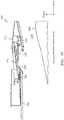
- a turbo fan engine that utilizes a cascade type thrust reverser
- the system 100 includes a sleeve 102 that is translated or moved in, e.g., an aft direction in order to expose cascades 104 as part of the deployment of the thrust reverser ( FIG. 1B ).
- the sleeve 102 is translated or moved in, e.g., a forward (FWD) direction, such that the sleeve 102 may close the passage of air through the cascades 104 ( FIG. 1A ).
- FWD forward
- the length of the sleeve 102 stroke between the stowed and deployed positions is denoted as reference character 102a in FIG. 1B .
- a blocker door 108 is typically pivotally attached to the sleeve 102 within the thrust reverser.
- FIG. 1B illustrates the blocker door 108 of the system 100 hinged to the sleeve 102 near a point 110.
- the door 108 is attached to the inner fixed structure (IFS) 114 of the thrust reverser via a drag link 112 and associated drag link fitting 116.
- IFS inner fixed structure
- the door 108 forms, in part, the outer surface of the bypass air duct 124.
- the drag link 112 crosses this bypass duct 124 in attaching to the IFS 114 at the fitting 116.
- FIGS. 1A and 1B may be contrasted with their respective positions when the thrust reverser is stowed; the stowed positions are shown in FIG. 1B via reference characters/dashed lines 108' and 112', respectively.
- the IFS 114 is shown in relation to an engine exhaust nozzle 134 and a centerbody 142.
- the drag link 112 lies within the airflow and generates drag losses on the engine, resulting in degraded efficiencies. Additionally, any steps and gaps around the blocker door 108 generate aerodynamic disturbances that reduce overall efficiency.
- aspects of the disclosure are directed to a system associated with a thrust reverser of an aircraft, comprising: a blocker door, and, a fan case, where when the thrust reverser is stowed the blocker door is stowed at least in part radially outboard of the fan case.
- the system further comprises a set of cascades configured to be stowed at least in part radially outboard of the fan case when the thrust reverser is stowed.
- the system further comprises a sleeve configured to translate in a substantially forward or aft reference direction based on a state of a deployment of the thrust reverser.
- the system further comprises a pushrod coupled to the blocker door at a first end of the pushrod.
- the system further comprises a delay mechanism coupled to a second end of the pushrod, the delay mechanism configured to implement a delay between a translation of the sleeve and a deployment of the blocker door into a bypass duct.
- the delay mechanism comprises a track coupled to a fixed structure, a carrier coupled to the second end of the pushrod, the carrier configured to traverse the track, and a latch coupled to the carrier, the latch including a first catch configured to selectively be seated in a first detent formed in the sleeve and a second catch configured to selectively be seated in a second detent formed in the fixed structure.
- the first catch is configured to be seated in the first detent when the thrust reverser is stowed, and the second catch is configured to be seated in the second detent when the thrust reverser is fully deployed.
- the system further comprises a roller coupled to the sleeve, the roller configured to translate in the substantially forward or aft reference direction coinciding with the translation of the sleeve.
- the latch, the carrier, and the pushrod are configured to translate with the sleeve
- the sleeve is configured to translate independently of the latch, the carrier, and the pushrod.
- the system further comprises a cartridge coupled to the sleeve and the blocker door.
- a thrust reverser system for an aircraft propulsion system comprising: a fixed structure, a translating sleeve configured to translate relative to the fixed structure, at least one blocker door pivotally mounted to the translating sleeve, and a rod coupled on a first end thereof to the fixed structure and on a second end opposite the first end to the at least one blocker door, where during a first phase of thrust reverser deployment the blocker door translates with the translating sleeve when the translating sleeve is translating toward its deployed position and does not rotate, and during a second phase of thrust reverser deployment following the first phase, the blocker door pivots relative to the translating sleeve from a stowed position to a deployed position.
- the thrust reverser system further comprises a lost motion device interposed between the fixed structure and the blocker door.
- the lost motion device is coupled to the second end of the rod and to the blocker door.
- the lost motion device is coupled to the first end of the rod and to the fixed structure.
- the lost motion device is configured to permit the first end of the rod to slide relative to the fixed structure in the first phase of thrust reverser deployment.
- the lost motion device is configured to permit the translating sleeve to translate independently of the rod in the second phase of thrust reverser deployment.
- the first end of the rod is forward of the second end of the rod.
- the thrust reverser system further comprises a cartridge pivotally coupled to the blocker door and pivotally coupled to the translating sleeve, where the cartridge is configured to ensure that loads on the blocker door do not reverse or change orientation during blocker door deployment by applying a compression or tension force, and where the cartridge is configured to provide a preload on the blocker door when the blocker door is stowed.
- the thrust reverser system further comprises a set of cascades fixed to the translating sleeve.
- connections are set forth between elements in the following description and in the drawings (the contents of which are included in this disclosure by way of reference). It is noted that these connections are general and, unless specified otherwise, may be direct or indirect and that this specification is not intended to be limiting in this respect.
- a coupling between two or more entities may refer to a direct connection or an indirect connection.
- An indirect connection may incorporate one or more intervening entities.
- arrays of cascades and blocker doors may be at least partially stowed above, or radially outboard of, a fan case.
- a delay mechanism may be incorporated in connection with a blocker door to delay the rotation/deployment of the blocker door until it is clear of fixed structure.
- FIGS. 2A-2E components of a system 200 associated with a thrust reverser are illustrated. Taking FIGS. 2A-2E in order/sequence, the figures reflect a progression of the deployment of the thrust reverser from a stowed state to a fully deployed state.
- FIG. 2A represents the thrust reverser in a stowed state
- FIG. 2E represents the thrust reverser in a fully deployed state.
- FIG. 2A an arrangement of a bypass duct 224 that is at least partially located/defined between an IFS 228 and a translating sleeve 232 is illustrated.
- a blocker door 236 is hidden/concealed from the bypass duct 224 and forms no part of its boundary surfaces.
- One way to achieve this is by storing the blocker doors 236 "inside" of the sleeve 232 when the thrust reverser is stowed.
- a set/array of cascades 240 is not exposed to the bypass duct 224 when the thrust reverser is stowed.
- the blocker door 236 and the cascades 240 may be stowed at least partly over/radially outboard of a fan case 246 (the fan case is the structure radially surrounding the fan for containment purposes and joined to the engine case) for packaging reasons.
- the kinematic structure of the thrust reverser will deploy the blocker doors 236 by translating them in a forward to aft direction away from their storage location at least partly outside of the fan case 246, and by rotating them into position to block the fan duct 224.
- the cascades/cascade segments 240 will also be deployed by translating in a forward to aft direction to their deployed position.
- the kinematic structure moves the sleeve 232 in a generally forward to aft direction away from the blocker doors 236 before beginning rotation of the blocker doors 236 to their deployed positions, to avoid a clash.
- FIGS. 2A-2E schematically illustrate a sectional view of a thrust reverser half, showing in an illustrative manner a single blocker door 236 and cascade segment 240.
- a full set of blocker doors 236 and cascade segments 240 are disposed circumferentially around the thrust reverser.
- the thrust reverser may be constructed in two halves (or more segments) that attach together during use of the propulsion system, in which case each thrust reverser half includes a share of the almost circumferential array of radially disposed blocker doors 236 and cascade segments 240.
- the blocker door 236 may be of conventional construction and is supported pivotally around one point by a connection to the sleeve 232, and is supported pivotally around another point by the aft end of a pushrod 256.
- the blocker door 236 may also be pivotally attached to an optional, adjustable length cartridge 270.
- the sleeve 232 may also be of conventional construction and may be supported on the fixed structure of the thrust reverser for translating movement relative thereto. In a conventional manner, the sleeve 232 may be mounted via sliders and grooves to a pair of beams (not pictured) of the fixed structure of the thrust reverser, or may be mounted in another fashion as will be apparent to those of ordinary skill in this art.
- a thrust reverser actuation system (not pictured) is used to translate the sleeve 232 from a stowed position to a deployed position, and back again to the stowed position.
- the thrust reverser actuation system may constitute conventional hydraulic or pneumatic linear actuators disposed between the sleeve 232 and the fixed structure of the thrust reverser.
- the thrust reverser actuation system could be any suitable system, and need not be illustrated or further described herein.
- the sleeve 232, the blocker door 236, the pushrod 256, and the fixed structure of the thrust reverser constitute a four-bar kinematic mechanism, with translating motion also sometimes possible between two of the links, in the illustrated case between the pushrod and the fixed structure.
- the cartridge 270 joins two of the links, but is extensible and does not during normal operation restrict movement of the links, but rather applies a compressive or tension force between them.
- FIG. 2A shows the pushrod 256, a delay mechanism 264, and the cartridge 270.
- Pushrod 256 is any generally rigid, non-extensible and non-retractable fixed length structure.
- a first, aft end of the pushrod 256 may be pivotally coupled to the blocker door 236.
- the delay mechanism 264 may be pivotally coupled to a second, forward end of the pushrod 256.
- the delay mechanism 264 may be used to implement lost motion between the translation of the sleeve 232 and the forward end of the pushrod 256, and ultimately the deployment of the blocker door 236 into the bypass duct 224.
- the delay mechanism 264 fixes the forward end of the pushrod 256 to the sleeve 232 during a first stage of deployment, such that the forward end of the pushrod and the sleeve 232 move together.
- the delay mechanism 264 fixes the forward end of the pushrod 256 to the fixed structure of the thrust reverser so that the forward end of the pushrod does not move aft any further, while the translating sleeve continues its aft deployment.
- the optional cartridge 270 may be pivotally coupled to the blocker door 236 and pivotally coupled to the sleeve 232.
- the cartridge 270 may be used to ensure that certain loads on the blocker door 236 do not reverse/change direction/orientation during blocker door deployment by applying a biasing compression or tension force.
- the cartridge 270 may include a mechanical spring or a gas spring, or any other suitable structure for applying a biasing force, as will be apparent to those of ordinary skill in this art.
- the cartridge 270 may extend to facilitate the deployment/rotation of the blocker door 236.
- the cartridge 270 may also provide a preload on the stowed blocker door 236 to reduce vibrations.
- FIG. 2B illustrates the system 200 during the initial stages of thrust reverser deployment as the thrust reverser actuation system translates the sleeve 232 in an aft direction relative to the fixed structure of the thrust reverser.
- the delay mechanism 264 and the forward end of the pushrod 256 are locked to the sleeve 232, and are translating aft at the same rate as the sleeve 232.
- the blocker door 236 has not deployed into the fan air duct, i.e. has not rotated relative to the sleeve 232.
- the delay mechanism 264 may unlock from the sleeve 232 and may lock to fixed structure of the thrust reverser. As a result, the forward end of pushrod 256 is then rotationally coupled/locked to the fixed structure and will no longer translate aft as the sleeve continues its aft translation.
- the sleeve 232 may be translated aft to such an extent that the door 236 may begin to rotate (e.g., counter clockwise in the example shown) into the bypass duct 224.
- the rotation of the blocker door 236 is a result of the door's pivotal connection to the sleeve 232, and its pivotal connection to the aft end of the pushrod 256. Because the forward end of the pushrod 256 is now fixed to the thrust reverser fixed structure, and the pivotal connection of the blocker door 236 to the sleeve 232 translates aft, this relative motion produces a couple that rotates the pushrod 256 clockwise and the blocker door 236 counterclockwise (in the perspective of FIG. 2D ) to its deployed position. In its deployed position, the blocker door 236 may redirect at least a portion of the bypass air flow in the bypass duct 224 through the cascades 240 in order to generate reverse thrust.
- FIG. 2E shows the completed deployment of the thrust reverser. Stowing the thrust reverser and the blocker doors 236 occurs in the same manner as the deployment, but in reverse order.
- the cascades 240 are shown as translating/moving with the sleeve 232 (illustratively in a forward-to-aft reference direction).
- the cascades 240 may be fixed to the sleeve 232 to provide for such motion.
- a system 300 is shown. It should be apparent to those or ordinary skill in this art that the system 300 is just one example of a mechanism that could constitute the delay mechanism 264. Many other designs would work and may be selected to suit a particular application.
- the system 300 is shown as including some of the components/devices described above in connection with the system 200 of FIGS. 2A-2E , and therefore, a complete re-description is omitted for the sake of brevity.
- the system 300 is shown as including a first detent 332 formed in the sleeve 232 and a second detent 336 formed in a portion 356 of the thrust reverser fixed structure.
- the detents 332 and 336 may be configured to selectively seat/receive/lock one or more catches (e.g., catches 340a and 340b) associated with a trigger/latch 340 as a function of the state of the thrust reverser (e.g., stowed, partially deployed, fully deployed).
- a reference arrow 344 indicates a direction in which the latch 340 may be biased. Such biasing may be accomplished through use of a torsion spring or any other applicable device, as will be apparent to those of ordinary skill in this art.
- the latch 340 may be coupled to a structure such as a carrier 350.
- the carrier 350 may be pivotally coupled to the forward end of pushrod 256.
- the carrier 350 may be configured to traverse a track 354 coupled (e.g., attached) to the thrust reverser fixed structure.
- the carrier 350 may be configured to traverse or translate within the track 354 in a substantially forward or aft reference direction.
- the sleeve 232 may be coupled to, or include, a roller 362.
- the roller 362 may selectively engage the latch 340 when the sleeve 232 is moving in the forward direction during stowing.
- the roller 362 may engage the latch 340 to counteract the torsional bias of the latch 340 and pivot it around its pivotal attachment point to the carrier 350.
- the catch 340a of the latch 340 is shown as being at least partially seated/received within the sleeve detent 332 (and not in the fixed structure detent 336).
- the latch 340, the carrier 350, and the forward end of pushrod 256 may translate forward to aft along with the with the forward to aft translation of the sleeve 232. In this state, the forward end of pushrod 256 slides relative to the fixed structure 356.
- the latch 340 may begin to rotate (clockwise in FIG. 3C ). This rotation of the latch 340 may start to decouple/unseat/unlock the catch 340a of latch 340 from the sleeve detent 332 (and hence, the sleeve 232) and couple/seat/lock the catch 340b of latch 340 to the fixed structure detent 336.
- the catch 340b of latch 340 may be seated within/engaged to the fixed structure detent 336.
- the latch 340 may be biased to rotate into the position shown in FIG. 3D .
- the sleeve 232 will do so independent of the latch 340, the carrier 350, and the pushrod 256, which are, rather, coupled to and prevented from moving by the fixed structure 356 of the thrust reverser.
- the progression of the system 300 in transitioning from FIGS. 3A-3E may represent the various states/stages of deployment of the thrust reverser and may correspond to the same sequence described above in relation to FIGS. 2A-2E (e.g., FIG. 3A may correspond to FIG. 2A , FIG. 3B may correspond to FIG. 2B , etc.).
- the stowing of the thrust reverser may be accomplished in a similar manner, but in reverse order.
- the catch 340b is to be disengaged from the detent 336
- the latch 340 must rotate in an opposite direction (counter-clockwise in the figures). This rotation of the latch 340 against its biasing force is accomplished by the roller 362 attached to the sleeve 332, which applies a force to the latch 340 to rotate it in a counter-clockwise direction (in the perspective of the figures).
- the lost motion device may be positioned between the pushrod 256 and the blocker door 236, rather than between the pushrod 256 and the fixed structure 356, and operate in a similar manner.
Landscapes
- Engineering & Computer Science (AREA)
- Mechanical Engineering (AREA)
- General Engineering & Computer Science (AREA)
- Chemical & Material Sciences (AREA)
- Combustion & Propulsion (AREA)
- Lock And Its Accessories (AREA)
- Aviation & Aerospace Engineering (AREA)
- Power-Operated Mechanisms For Wings (AREA)
Applications Claiming Priority (1)
| Application Number | Priority Date | Filing Date | Title |
|---|---|---|---|
| US14/994,898 US10533519B2 (en) | 2016-01-13 | 2016-01-13 | Translating cascade hidden blocker door thrust reverser |
Publications (2)
| Publication Number | Publication Date |
|---|---|
| EP3193002A1 true EP3193002A1 (fr) | 2017-07-19 |
| EP3193002B1 EP3193002B1 (fr) | 2020-07-29 |
Family
ID=57794202
Family Applications (1)
| Application Number | Title | Priority Date | Filing Date |
|---|---|---|---|
| EP17151250.2A Active EP3193002B1 (fr) | 2016-01-13 | 2017-01-12 | Inverseur de poussée à cascade translatable et porte de blocage escamotée |
Country Status (2)
| Country | Link |
|---|---|
| US (1) | US10533519B2 (fr) |
| EP (1) | EP3193002B1 (fr) |
Cited By (2)
| Publication number | Priority date | Publication date | Assignee | Title |
|---|---|---|---|---|
| FR3070439A1 (fr) * | 2017-08-31 | 2019-03-01 | Safran Nacelles | Nacelle pour turboreacteur comportant un inverseur de poussee a grilles |
| FR3115836A1 (fr) * | 2020-11-03 | 2022-05-06 | Airbus Operations | Turboreacteur double flux comportant une serie de lames rotatives pour obturer la veine du flux secondaire |
Families Citing this family (8)
| Publication number | Priority date | Publication date | Assignee | Title |
|---|---|---|---|---|
| FR3067406B1 (fr) * | 2017-06-13 | 2019-07-12 | Airbus Operations | Systeme d'inverseur de poussee presentant des perturbations aerodynamiques limitees |
| US10794328B2 (en) * | 2018-07-06 | 2020-10-06 | Rohr, Inc. | Thrust reverser with blocker door folding linkage |
| FR3092623A1 (fr) * | 2019-02-07 | 2020-08-14 | Airbus Operations (S.A.S.) | Turboréacteur comportant un mécanisme d’entrainement d’un inverseur de poussée |
| US11391241B2 (en) | 2019-08-05 | 2022-07-19 | Rohr, Inc. | Drive system for translating structure |
| US10995701B2 (en) | 2019-09-05 | 2021-05-04 | Rohr, Inc. | Translating sleeve thrust reverser assembly |
| US11913406B2 (en) | 2020-04-07 | 2024-02-27 | Rohr, Inc. | Hidden door thrust reverser system for an aircraft propulsion system |
| US11719190B2 (en) | 2021-10-05 | 2023-08-08 | Rohr, Inc. | Thrust reverser system with hidden turning door |
| FR3128207A1 (fr) * | 2021-10-15 | 2023-04-21 | Airbus Operations | Turboréacteur double flux comportant des déflecteurs mobiles et un système d’actionnement des déflecteurs |
Citations (3)
| Publication number | Priority date | Publication date | Assignee | Title |
|---|---|---|---|---|
| US20130205753A1 (en) * | 2012-02-14 | 2013-08-15 | Rolls-Royce Deutschland Ltd & Co Kg | Aircraft gas turbine thrust-reversing device |
| DE102013206595A1 (de) * | 2013-04-12 | 2014-10-16 | Deutsches Zentrum für Luft- und Raumfahrt e.V. | Strahltriebwerk |
| EP3103995A2 (fr) * | 2015-06-09 | 2016-12-14 | The Boeing Company | Procédé et appareil inverseur de poussée |
Family Cites Families (17)
| Publication number | Priority date | Publication date | Assignee | Title |
|---|---|---|---|---|
| US3036431A (en) * | 1959-09-08 | 1962-05-29 | Boeing Co | Thrust reverser for jet engines |
| US3262269A (en) * | 1965-06-07 | 1966-07-26 | Gen Electric | Thrust reverser |
| US3500646A (en) | 1968-04-19 | 1970-03-17 | Rohr Corp | Thrust reverser |
| US4147029A (en) * | 1976-01-02 | 1979-04-03 | General Electric Company | Long duct mixed flow gas turbine engine |
| FR2752017B1 (fr) * | 1996-08-01 | 1998-10-16 | Hispano Suiza Sa | Inverseur de poussee de turboreacteur a portes formant ecopes |
| FR2776023B1 (fr) * | 1998-03-12 | 2000-04-07 | Hispano Suiza Sa | Inverseur de poussee de turboreacteur a portes formant ecopes associees a une grille mobile |
| US7264203B2 (en) * | 2003-10-02 | 2007-09-04 | The Nordam Group, Inc. | Spider actuated thrust reverser |
| GB0606982D0 (en) * | 2006-04-07 | 2006-05-17 | Rolls Royce Plc | Aeroengine thrust reverser |
| FR2933144B1 (fr) | 2008-06-26 | 2012-08-17 | Airbus France | Nacelle pour aeronef comportant des moyens inverseurs de poussee et aeronef comportant au moins une telle nacelle |
| FR2960917B1 (fr) * | 2010-06-03 | 2012-05-18 | Aircelle Sa | Inverseur de poussee a section de tuyere variable verrouillable |
| US20120079805A1 (en) * | 2010-09-30 | 2012-04-05 | Alan Roy Stuart | Thrust reverser assembly |
| FR2966883B1 (fr) * | 2010-11-03 | 2012-11-02 | Aircelle Sa | Dispositif d'inversion de poussee sans bielle dans la veine |
| FR2978802B1 (fr) * | 2011-08-05 | 2017-07-14 | Aircelle Sa | Inverseur a grilles mobiles et tuyere variable par translation |
| US8904751B2 (en) * | 2012-04-30 | 2014-12-09 | Middle River Aircraft Systems | Thrust reverser assembly and method of operation |
| FR2994586B1 (fr) * | 2012-08-20 | 2014-08-08 | Aircelle Sa | Ensemble de poussee a grilles pour turboreacteur d'aeronef |
| GB201219366D0 (en) * | 2012-10-29 | 2012-12-12 | Rolls Royce Deutschland & Co Kg | Aeroengine thrust reverser arrangement |
| US9109536B2 (en) * | 2013-03-14 | 2015-08-18 | Woodward Hrt, Inc. | Engine thrust reverser lock |
-
2016
- 2016-01-13 US US14/994,898 patent/US10533519B2/en active Active
-
2017
- 2017-01-12 EP EP17151250.2A patent/EP3193002B1/fr active Active
Patent Citations (3)
| Publication number | Priority date | Publication date | Assignee | Title |
|---|---|---|---|---|
| US20130205753A1 (en) * | 2012-02-14 | 2013-08-15 | Rolls-Royce Deutschland Ltd & Co Kg | Aircraft gas turbine thrust-reversing device |
| DE102013206595A1 (de) * | 2013-04-12 | 2014-10-16 | Deutsches Zentrum für Luft- und Raumfahrt e.V. | Strahltriebwerk |
| EP3103995A2 (fr) * | 2015-06-09 | 2016-12-14 | The Boeing Company | Procédé et appareil inverseur de poussée |
Cited By (6)
| Publication number | Priority date | Publication date | Assignee | Title |
|---|---|---|---|---|
| FR3070439A1 (fr) * | 2017-08-31 | 2019-03-01 | Safran Nacelles | Nacelle pour turboreacteur comportant un inverseur de poussee a grilles |
| WO2019043343A1 (fr) * | 2017-08-31 | 2019-03-07 | Safran Nacelles | Nacelle pour turboreacteur comportant un inverseur de poussee a grilles |
| CN111065810A (zh) * | 2017-08-31 | 2020-04-24 | 赛峰短舱公司 | 包括叶栅推力反向器的涡轮喷气发动机机舱 |
| US11293377B2 (en) | 2017-08-31 | 2022-04-05 | Safran Nacelles | Turbojet engine nacelle including a cascade thrust reverser |
| FR3115836A1 (fr) * | 2020-11-03 | 2022-05-06 | Airbus Operations | Turboreacteur double flux comportant une serie de lames rotatives pour obturer la veine du flux secondaire |
| US11486335B2 (en) | 2020-11-03 | 2022-11-01 | Airbus Operations Sas | Turbofan engine comprising a set of rotatable blades for blocking off the bypass flow duct |
Also Published As
| Publication number | Publication date |
|---|---|
| US20170198659A1 (en) | 2017-07-13 |
| US10533519B2 (en) | 2020-01-14 |
| EP3193002B1 (fr) | 2020-07-29 |
Similar Documents
| Publication | Publication Date | Title |
|---|---|---|
| EP3193002B1 (fr) | Inverseur de poussée à cascade translatable et porte de blocage escamotée | |
| US11434850B2 (en) | Split sleeve hidden door thrust reverser | |
| US11073104B2 (en) | Translating cascade hidden blocker door thrust reverser | |
| CA2384651C (fr) | Inverseur de poussee a bras basculant | |
| JP6167266B2 (ja) | 逆推力装置アセンブリおよび動作の方法 | |
| EP3181882B1 (fr) | Inverseur de poussée à cascade translatable avec commande de porte de blocage | |
| US11149686B2 (en) | Thrust reverser assembly | |
| EP3059432B1 (fr) | Inverseur de poussée comprenant une découpe d'évitement du bec mobile d'une aile | |
| US11913406B2 (en) | Hidden door thrust reverser system for an aircraft propulsion system | |
| US10907577B2 (en) | Translating lock for pivot door thrust reverser | |
| US11396854B2 (en) | Hinge mechanism for pivot door thrust reversers | |
| US11300077B2 (en) | Deployable fairing for door reversers systems and methods | |
| EP3620643B1 (fr) | Carénage déployable pour systèmes inverseurs de porte et procédés | |
| CA3054710A1 (fr) | Systemes et procedes d'agencement de commande d'inverseur de poussee | |
| CA3015941A1 (fr) | Mecanisme de charniere destine a des inverseurs de poussee a porte pivot |
Legal Events
| Date | Code | Title | Description |
|---|---|---|---|
| PUAI | Public reference made under article 153(3) epc to a published international application that has entered the european phase |
Free format text: ORIGINAL CODE: 0009012 |
|
| STAA | Information on the status of an ep patent application or granted ep patent |
Free format text: STATUS: THE APPLICATION HAS BEEN PUBLISHED |
|
| AK | Designated contracting states |
Kind code of ref document: A1 Designated state(s): AL AT BE BG CH CY CZ DE DK EE ES FI FR GB GR HR HU IE IS IT LI LT LU LV MC MK MT NL NO PL PT RO RS SE SI SK SM TR |
|
| AX | Request for extension of the european patent |
Extension state: BA ME |
|
| STAA | Information on the status of an ep patent application or granted ep patent |
Free format text: STATUS: REQUEST FOR EXAMINATION WAS MADE |
|
| 17P | Request for examination filed |
Effective date: 20180119 |
|
| RBV | Designated contracting states (corrected) |
Designated state(s): AL AT BE BG CH CY CZ DE DK EE ES FI FR GB GR HR HU IE IS IT LI LT LU LV MC MK MT NL NO PL PT RO RS SE SI SK SM TR |
|
| STAA | Information on the status of an ep patent application or granted ep patent |
Free format text: STATUS: EXAMINATION IS IN PROGRESS |
|
| GRAP | Despatch of communication of intention to grant a patent |
Free format text: ORIGINAL CODE: EPIDOSNIGR1 |
|
| STAA | Information on the status of an ep patent application or granted ep patent |
Free format text: STATUS: GRANT OF PATENT IS INTENDED |
|
| INTG | Intention to grant announced |
Effective date: 20200224 |
|
| GRAS | Grant fee paid |
Free format text: ORIGINAL CODE: EPIDOSNIGR3 |
|
| GRAA | (expected) grant |
Free format text: ORIGINAL CODE: 0009210 |
|
| STAA | Information on the status of an ep patent application or granted ep patent |
Free format text: STATUS: THE PATENT HAS BEEN GRANTED |
|
| AK | Designated contracting states |
Kind code of ref document: B1 Designated state(s): AL AT BE BG CH CY CZ DE DK EE ES FI FR GB GR HR HU IE IS IT LI LT LU LV MC MK MT NL NO PL PT RO RS SE SI SK SM TR |
|
| REG | Reference to a national code |
Ref country code: CH Ref legal event code: EP |
|
| REG | Reference to a national code |
Ref country code: AT Ref legal event code: REF Ref document number: 1296092 Country of ref document: AT Kind code of ref document: T Effective date: 20200815 |
|
| REG | Reference to a national code |
Ref country code: IE Ref legal event code: FG4D |
|
| REG | Reference to a national code |
Ref country code: DE Ref legal event code: R096 Ref document number: 602017020376 Country of ref document: DE |
|
| REG | Reference to a national code |
Ref country code: LT Ref legal event code: MG4D |
|
| REG | Reference to a national code |
Ref country code: NL Ref legal event code: MP Effective date: 20200729 |
|
| REG | Reference to a national code |
Ref country code: AT Ref legal event code: MK05 Ref document number: 1296092 Country of ref document: AT Kind code of ref document: T Effective date: 20200729 |
|
| PG25 | Lapsed in a contracting state [announced via postgrant information from national office to epo] |
Ref country code: HR Free format text: LAPSE BECAUSE OF FAILURE TO SUBMIT A TRANSLATION OF THE DESCRIPTION OR TO PAY THE FEE WITHIN THE PRESCRIBED TIME-LIMIT Effective date: 20200729 Ref country code: LT Free format text: LAPSE BECAUSE OF FAILURE TO SUBMIT A TRANSLATION OF THE DESCRIPTION OR TO PAY THE FEE WITHIN THE PRESCRIBED TIME-LIMIT Effective date: 20200729 Ref country code: ES Free format text: LAPSE BECAUSE OF FAILURE TO SUBMIT A TRANSLATION OF THE DESCRIPTION OR TO PAY THE FEE WITHIN THE PRESCRIBED TIME-LIMIT Effective date: 20200729 Ref country code: AT Free format text: LAPSE BECAUSE OF FAILURE TO SUBMIT A TRANSLATION OF THE DESCRIPTION OR TO PAY THE FEE WITHIN THE PRESCRIBED TIME-LIMIT Effective date: 20200729 Ref country code: NO Free format text: LAPSE BECAUSE OF FAILURE TO SUBMIT A TRANSLATION OF THE DESCRIPTION OR TO PAY THE FEE WITHIN THE PRESCRIBED TIME-LIMIT Effective date: 20201029 Ref country code: SE Free format text: LAPSE BECAUSE OF FAILURE TO SUBMIT A TRANSLATION OF THE DESCRIPTION OR TO PAY THE FEE WITHIN THE PRESCRIBED TIME-LIMIT Effective date: 20200729 Ref country code: BG Free format text: LAPSE BECAUSE OF FAILURE TO SUBMIT A TRANSLATION OF THE DESCRIPTION OR TO PAY THE FEE WITHIN THE PRESCRIBED TIME-LIMIT Effective date: 20201029 Ref country code: FI Free format text: LAPSE BECAUSE OF FAILURE TO SUBMIT A TRANSLATION OF THE DESCRIPTION OR TO PAY THE FEE WITHIN THE PRESCRIBED TIME-LIMIT Effective date: 20200729 Ref country code: GR Free format text: LAPSE BECAUSE OF FAILURE TO SUBMIT A TRANSLATION OF THE DESCRIPTION OR TO PAY THE FEE WITHIN THE PRESCRIBED TIME-LIMIT Effective date: 20201030 Ref country code: PT Free format text: LAPSE BECAUSE OF FAILURE TO SUBMIT A TRANSLATION OF THE DESCRIPTION OR TO PAY THE FEE WITHIN THE PRESCRIBED TIME-LIMIT Effective date: 20201130 |
|
| PG25 | Lapsed in a contracting state [announced via postgrant information from national office to epo] |
Ref country code: IS Free format text: LAPSE BECAUSE OF FAILURE TO SUBMIT A TRANSLATION OF THE DESCRIPTION OR TO PAY THE FEE WITHIN THE PRESCRIBED TIME-LIMIT Effective date: 20201129 Ref country code: LV Free format text: LAPSE BECAUSE OF FAILURE TO SUBMIT A TRANSLATION OF THE DESCRIPTION OR TO PAY THE FEE WITHIN THE PRESCRIBED TIME-LIMIT Effective date: 20200729 Ref country code: RS Free format text: LAPSE BECAUSE OF FAILURE TO SUBMIT A TRANSLATION OF THE DESCRIPTION OR TO PAY THE FEE WITHIN THE PRESCRIBED TIME-LIMIT Effective date: 20200729 Ref country code: PL Free format text: LAPSE BECAUSE OF FAILURE TO SUBMIT A TRANSLATION OF THE DESCRIPTION OR TO PAY THE FEE WITHIN THE PRESCRIBED TIME-LIMIT Effective date: 20200729 |
|
| PG25 | Lapsed in a contracting state [announced via postgrant information from national office to epo] |
Ref country code: NL Free format text: LAPSE BECAUSE OF FAILURE TO SUBMIT A TRANSLATION OF THE DESCRIPTION OR TO PAY THE FEE WITHIN THE PRESCRIBED TIME-LIMIT Effective date: 20200729 |
|
| PG25 | Lapsed in a contracting state [announced via postgrant information from national office to epo] |
Ref country code: CZ Free format text: LAPSE BECAUSE OF FAILURE TO SUBMIT A TRANSLATION OF THE DESCRIPTION OR TO PAY THE FEE WITHIN THE PRESCRIBED TIME-LIMIT Effective date: 20200729 Ref country code: DK Free format text: LAPSE BECAUSE OF FAILURE TO SUBMIT A TRANSLATION OF THE DESCRIPTION OR TO PAY THE FEE WITHIN THE PRESCRIBED TIME-LIMIT Effective date: 20200729 Ref country code: RO Free format text: LAPSE BECAUSE OF FAILURE TO SUBMIT A TRANSLATION OF THE DESCRIPTION OR TO PAY THE FEE WITHIN THE PRESCRIBED TIME-LIMIT Effective date: 20200729 Ref country code: SM Free format text: LAPSE BECAUSE OF FAILURE TO SUBMIT A TRANSLATION OF THE DESCRIPTION OR TO PAY THE FEE WITHIN THE PRESCRIBED TIME-LIMIT Effective date: 20200729 Ref country code: IT Free format text: LAPSE BECAUSE OF FAILURE TO SUBMIT A TRANSLATION OF THE DESCRIPTION OR TO PAY THE FEE WITHIN THE PRESCRIBED TIME-LIMIT Effective date: 20200729 Ref country code: EE Free format text: LAPSE BECAUSE OF FAILURE TO SUBMIT A TRANSLATION OF THE DESCRIPTION OR TO PAY THE FEE WITHIN THE PRESCRIBED TIME-LIMIT Effective date: 20200729 |
|
| REG | Reference to a national code |
Ref country code: DE Ref legal event code: R097 Ref document number: 602017020376 Country of ref document: DE |
|
| PG25 | Lapsed in a contracting state [announced via postgrant information from national office to epo] |
Ref country code: AL Free format text: LAPSE BECAUSE OF FAILURE TO SUBMIT A TRANSLATION OF THE DESCRIPTION OR TO PAY THE FEE WITHIN THE PRESCRIBED TIME-LIMIT Effective date: 20200729 |
|
| PLBE | No opposition filed within time limit |
Free format text: ORIGINAL CODE: 0009261 |
|
| STAA | Information on the status of an ep patent application or granted ep patent |
Free format text: STATUS: NO OPPOSITION FILED WITHIN TIME LIMIT |
|
| PG25 | Lapsed in a contracting state [announced via postgrant information from national office to epo] |
Ref country code: SK Free format text: LAPSE BECAUSE OF FAILURE TO SUBMIT A TRANSLATION OF THE DESCRIPTION OR TO PAY THE FEE WITHIN THE PRESCRIBED TIME-LIMIT Effective date: 20200729 |
|
| 26N | No opposition filed |
Effective date: 20210430 |
|
| PG25 | Lapsed in a contracting state [announced via postgrant information from national office to epo] |
Ref country code: SI Free format text: LAPSE BECAUSE OF FAILURE TO SUBMIT A TRANSLATION OF THE DESCRIPTION OR TO PAY THE FEE WITHIN THE PRESCRIBED TIME-LIMIT Effective date: 20200729 Ref country code: MC Free format text: LAPSE BECAUSE OF FAILURE TO SUBMIT A TRANSLATION OF THE DESCRIPTION OR TO PAY THE FEE WITHIN THE PRESCRIBED TIME-LIMIT Effective date: 20200729 |
|
| REG | Reference to a national code |
Ref country code: CH Ref legal event code: PL |
|
| PG25 | Lapsed in a contracting state [announced via postgrant information from national office to epo] |
Ref country code: LU Free format text: LAPSE BECAUSE OF NON-PAYMENT OF DUE FEES Effective date: 20210112 |
|
| REG | Reference to a national code |
Ref country code: BE Ref legal event code: MM Effective date: 20210131 |
|
| PG25 | Lapsed in a contracting state [announced via postgrant information from national office to epo] |
Ref country code: CH Free format text: LAPSE BECAUSE OF NON-PAYMENT OF DUE FEES Effective date: 20210131 Ref country code: LI Free format text: LAPSE BECAUSE OF NON-PAYMENT OF DUE FEES Effective date: 20210131 |
|
| PG25 | Lapsed in a contracting state [announced via postgrant information from national office to epo] |
Ref country code: IE Free format text: LAPSE BECAUSE OF NON-PAYMENT OF DUE FEES Effective date: 20210112 |
|
| PG25 | Lapsed in a contracting state [announced via postgrant information from national office to epo] |
Ref country code: BE Free format text: LAPSE BECAUSE OF NON-PAYMENT OF DUE FEES Effective date: 20210131 |
|
| PG25 | Lapsed in a contracting state [announced via postgrant information from national office to epo] |
Ref country code: HU Free format text: LAPSE BECAUSE OF FAILURE TO SUBMIT A TRANSLATION OF THE DESCRIPTION OR TO PAY THE FEE WITHIN THE PRESCRIBED TIME-LIMIT; INVALID AB INITIO Effective date: 20170112 |
|
| PG25 | Lapsed in a contracting state [announced via postgrant information from national office to epo] |
Ref country code: CY Free format text: LAPSE BECAUSE OF FAILURE TO SUBMIT A TRANSLATION OF THE DESCRIPTION OR TO PAY THE FEE WITHIN THE PRESCRIBED TIME-LIMIT Effective date: 20200729 |
|
| PGFP | Annual fee paid to national office [announced via postgrant information from national office to epo] |
Ref country code: GB Payment date: 20231219 Year of fee payment: 8 |
|
| PGFP | Annual fee paid to national office [announced via postgrant information from national office to epo] |
Ref country code: FR Payment date: 20231219 Year of fee payment: 8 |
|
| PG25 | Lapsed in a contracting state [announced via postgrant information from national office to epo] |
Ref country code: MK Free format text: LAPSE BECAUSE OF FAILURE TO SUBMIT A TRANSLATION OF THE DESCRIPTION OR TO PAY THE FEE WITHIN THE PRESCRIBED TIME-LIMIT Effective date: 20200729 |
|
| PGFP | Annual fee paid to national office [announced via postgrant information from national office to epo] |
Ref country code: DE Payment date: 20231219 Year of fee payment: 8 |