EP3192989A1 - Exhaust gas purification system - Google Patents
Exhaust gas purification system Download PDFInfo
- Publication number
- EP3192989A1 EP3192989A1 EP15839269.6A EP15839269A EP3192989A1 EP 3192989 A1 EP3192989 A1 EP 3192989A1 EP 15839269 A EP15839269 A EP 15839269A EP 3192989 A1 EP3192989 A1 EP 3192989A1
- Authority
- EP
- European Patent Office
- Prior art keywords
- nox
- control
- injection amount
- exhaust
- temperature
- Prior art date
- Legal status (The legal status is an assumption and is not a legal conclusion. Google has not performed a legal analysis and makes no representation as to the accuracy of the status listed.)
- Granted
Links
- 238000000746 purification Methods 0.000 title claims abstract description 17
- 239000003054 catalyst Substances 0.000 claims abstract description 89
- 239000000446 fuel Substances 0.000 claims abstract description 73
- 230000009467 reduction Effects 0.000 claims abstract description 46
- 230000008929 regeneration Effects 0.000 claims abstract description 30
- 238000011069 regeneration method Methods 0.000 claims abstract description 30
- 238000002485 combustion reaction Methods 0.000 claims abstract description 13
- 238000002347 injection Methods 0.000 claims description 142
- 239000007924 injection Substances 0.000 claims description 142
- 230000005484 gravity Effects 0.000 claims description 5
- 238000010926 purge Methods 0.000 abstract description 116
- 229910052815 sulfur oxide Inorganic materials 0.000 description 77
- 239000007789 gas Substances 0.000 description 30
- 238000000034 method Methods 0.000 description 16
- 238000011144 upstream manufacturing Methods 0.000 description 16
- 238000007254 oxidation reaction Methods 0.000 description 15
- 230000003647 oxidation Effects 0.000 description 14
- 238000010586 diagram Methods 0.000 description 13
- 230000008569 process Effects 0.000 description 13
- 230000008859 change Effects 0.000 description 11
- 238000003795 desorption Methods 0.000 description 9
- 230000006866 deterioration Effects 0.000 description 8
- 230000004044 response Effects 0.000 description 8
- 238000002474 experimental method Methods 0.000 description 7
- 230000001186 cumulative effect Effects 0.000 description 5
- 230000008021 deposition Effects 0.000 description 4
- 238000007599 discharging Methods 0.000 description 4
- 230000035945 sensitivity Effects 0.000 description 3
- 230000001052 transient effect Effects 0.000 description 3
- 101000767160 Saccharomyces cerevisiae (strain ATCC 204508 / S288c) Intracellular protein transport protein USO1 Proteins 0.000 description 2
- 239000000919 ceramic Substances 0.000 description 2
- 238000005192 partition Methods 0.000 description 2
- 230000007704 transition Effects 0.000 description 2
- 239000004215 Carbon black (E152) Substances 0.000 description 1
- NINIDFKCEFEMDL-UHFFFAOYSA-N Sulfur Chemical compound [S] NINIDFKCEFEMDL-UHFFFAOYSA-N 0.000 description 1
- 229910052783 alkali metal Inorganic materials 0.000 description 1
- 150000001340 alkali metals Chemical class 0.000 description 1
- 230000005540 biological transmission Effects 0.000 description 1
- 238000006243 chemical reaction Methods 0.000 description 1
- 239000003638 chemical reducing agent Substances 0.000 description 1
- TXKMVPPZCYKFAC-UHFFFAOYSA-N disulfur monoxide Inorganic materials O=S=S TXKMVPPZCYKFAC-UHFFFAOYSA-N 0.000 description 1
- 230000000694 effects Effects 0.000 description 1
- 229930195733 hydrocarbon Natural products 0.000 description 1
- 150000002430 hydrocarbons Chemical class 0.000 description 1
- 229910017464 nitrogen compound Inorganic materials 0.000 description 1
- 150000002830 nitrogen compounds Chemical class 0.000 description 1
- 239000011148 porous material Substances 0.000 description 1
- 229910052717 sulfur Inorganic materials 0.000 description 1
- 239000011593 sulfur Substances 0.000 description 1
- XTQHKBHJIVJGKJ-UHFFFAOYSA-N sulfur monoxide Chemical compound S=O XTQHKBHJIVJGKJ-UHFFFAOYSA-N 0.000 description 1
Images


Classifications
-
- F—MECHANICAL ENGINEERING; LIGHTING; HEATING; WEAPONS; BLASTING
- F01—MACHINES OR ENGINES IN GENERAL; ENGINE PLANTS IN GENERAL; STEAM ENGINES
- F01N—GAS-FLOW SILENCERS OR EXHAUST APPARATUS FOR MACHINES OR ENGINES IN GENERAL; GAS-FLOW SILENCERS OR EXHAUST APPARATUS FOR INTERNAL COMBUSTION ENGINES
- F01N3/00—Exhaust or silencing apparatus having means for purifying, rendering innocuous, or otherwise treating exhaust
- F01N3/08—Exhaust or silencing apparatus having means for purifying, rendering innocuous, or otherwise treating exhaust for rendering innocuous
- F01N3/10—Exhaust or silencing apparatus having means for purifying, rendering innocuous, or otherwise treating exhaust for rendering innocuous by thermal or catalytic conversion of noxious components of exhaust
- F01N3/18—Exhaust or silencing apparatus having means for purifying, rendering innocuous, or otherwise treating exhaust for rendering innocuous by thermal or catalytic conversion of noxious components of exhaust characterised by methods of operation; Control
- F01N3/20—Exhaust or silencing apparatus having means for purifying, rendering innocuous, or otherwise treating exhaust for rendering innocuous by thermal or catalytic conversion of noxious components of exhaust characterised by methods of operation; Control specially adapted for catalytic conversion ; Methods of operation or control of catalytic converters
- F01N3/2006—Periodically heating or cooling catalytic reactors, e.g. at cold starting or overheating
- F01N3/2033—Periodically heating or cooling catalytic reactors, e.g. at cold starting or overheating using a fuel burner or introducing fuel into exhaust duct
-
- F—MECHANICAL ENGINEERING; LIGHTING; HEATING; WEAPONS; BLASTING
- F01—MACHINES OR ENGINES IN GENERAL; ENGINE PLANTS IN GENERAL; STEAM ENGINES
- F01N—GAS-FLOW SILENCERS OR EXHAUST APPARATUS FOR MACHINES OR ENGINES IN GENERAL; GAS-FLOW SILENCERS OR EXHAUST APPARATUS FOR INTERNAL COMBUSTION ENGINES
- F01N11/00—Monitoring or diagnostic devices for exhaust-gas treatment apparatus, e.g. for catalytic activity
- F01N11/007—Monitoring or diagnostic devices for exhaust-gas treatment apparatus, e.g. for catalytic activity the diagnostic devices measuring oxygen or air concentration downstream of the exhaust apparatus
-
- F—MECHANICAL ENGINEERING; LIGHTING; HEATING; WEAPONS; BLASTING
- F01—MACHINES OR ENGINES IN GENERAL; ENGINE PLANTS IN GENERAL; STEAM ENGINES
- F01N—GAS-FLOW SILENCERS OR EXHAUST APPARATUS FOR MACHINES OR ENGINES IN GENERAL; GAS-FLOW SILENCERS OR EXHAUST APPARATUS FOR INTERNAL COMBUSTION ENGINES
- F01N3/00—Exhaust or silencing apparatus having means for purifying, rendering innocuous, or otherwise treating exhaust
- F01N3/08—Exhaust or silencing apparatus having means for purifying, rendering innocuous, or otherwise treating exhaust for rendering innocuous
- F01N3/0807—Exhaust or silencing apparatus having means for purifying, rendering innocuous, or otherwise treating exhaust for rendering innocuous by using absorbents or adsorbents
- F01N3/0814—Exhaust or silencing apparatus having means for purifying, rendering innocuous, or otherwise treating exhaust for rendering innocuous by using absorbents or adsorbents combined with catalytic converters, e.g. NOx absorption/storage reduction catalysts
-
- F—MECHANICAL ENGINEERING; LIGHTING; HEATING; WEAPONS; BLASTING
- F01—MACHINES OR ENGINES IN GENERAL; ENGINE PLANTS IN GENERAL; STEAM ENGINES
- F01N—GAS-FLOW SILENCERS OR EXHAUST APPARATUS FOR MACHINES OR ENGINES IN GENERAL; GAS-FLOW SILENCERS OR EXHAUST APPARATUS FOR INTERNAL COMBUSTION ENGINES
- F01N3/00—Exhaust or silencing apparatus having means for purifying, rendering innocuous, or otherwise treating exhaust
- F01N3/08—Exhaust or silencing apparatus having means for purifying, rendering innocuous, or otherwise treating exhaust for rendering innocuous
- F01N3/0807—Exhaust or silencing apparatus having means for purifying, rendering innocuous, or otherwise treating exhaust for rendering innocuous by using absorbents or adsorbents
- F01N3/0828—Exhaust or silencing apparatus having means for purifying, rendering innocuous, or otherwise treating exhaust for rendering innocuous by using absorbents or adsorbents characterised by the absorbed or adsorbed substances
- F01N3/0842—Nitrogen oxides
-
- F—MECHANICAL ENGINEERING; LIGHTING; HEATING; WEAPONS; BLASTING
- F01—MACHINES OR ENGINES IN GENERAL; ENGINE PLANTS IN GENERAL; STEAM ENGINES
- F01N—GAS-FLOW SILENCERS OR EXHAUST APPARATUS FOR MACHINES OR ENGINES IN GENERAL; GAS-FLOW SILENCERS OR EXHAUST APPARATUS FOR INTERNAL COMBUSTION ENGINES
- F01N3/00—Exhaust or silencing apparatus having means for purifying, rendering innocuous, or otherwise treating exhaust
- F01N3/08—Exhaust or silencing apparatus having means for purifying, rendering innocuous, or otherwise treating exhaust for rendering innocuous
- F01N3/0807—Exhaust or silencing apparatus having means for purifying, rendering innocuous, or otherwise treating exhaust for rendering innocuous by using absorbents or adsorbents
- F01N3/0871—Regulation of absorbents or adsorbents, e.g. purging
- F01N3/0885—Regeneration of deteriorated absorbents or adsorbents, e.g. desulfurization of NOx traps
-
- F—MECHANICAL ENGINEERING; LIGHTING; HEATING; WEAPONS; BLASTING
- F01—MACHINES OR ENGINES IN GENERAL; ENGINE PLANTS IN GENERAL; STEAM ENGINES
- F01N—GAS-FLOW SILENCERS OR EXHAUST APPARATUS FOR MACHINES OR ENGINES IN GENERAL; GAS-FLOW SILENCERS OR EXHAUST APPARATUS FOR INTERNAL COMBUSTION ENGINES
- F01N3/00—Exhaust or silencing apparatus having means for purifying, rendering innocuous, or otherwise treating exhaust
- F01N3/08—Exhaust or silencing apparatus having means for purifying, rendering innocuous, or otherwise treating exhaust for rendering innocuous
- F01N3/10—Exhaust or silencing apparatus having means for purifying, rendering innocuous, or otherwise treating exhaust for rendering innocuous by thermal or catalytic conversion of noxious components of exhaust
- F01N3/18—Exhaust or silencing apparatus having means for purifying, rendering innocuous, or otherwise treating exhaust for rendering innocuous by thermal or catalytic conversion of noxious components of exhaust characterised by methods of operation; Control
- F01N3/20—Exhaust or silencing apparatus having means for purifying, rendering innocuous, or otherwise treating exhaust for rendering innocuous by thermal or catalytic conversion of noxious components of exhaust characterised by methods of operation; Control specially adapted for catalytic conversion ; Methods of operation or control of catalytic converters
- F01N3/2066—Selective catalytic reduction [SCR]
-
- F—MECHANICAL ENGINEERING; LIGHTING; HEATING; WEAPONS; BLASTING
- F01—MACHINES OR ENGINES IN GENERAL; ENGINE PLANTS IN GENERAL; STEAM ENGINES
- F01N—GAS-FLOW SILENCERS OR EXHAUST APPARATUS FOR MACHINES OR ENGINES IN GENERAL; GAS-FLOW SILENCERS OR EXHAUST APPARATUS FOR INTERNAL COMBUSTION ENGINES
- F01N3/00—Exhaust or silencing apparatus having means for purifying, rendering innocuous, or otherwise treating exhaust
- F01N3/08—Exhaust or silencing apparatus having means for purifying, rendering innocuous, or otherwise treating exhaust for rendering innocuous
- F01N3/10—Exhaust or silencing apparatus having means for purifying, rendering innocuous, or otherwise treating exhaust for rendering innocuous by thermal or catalytic conversion of noxious components of exhaust
- F01N3/24—Exhaust or silencing apparatus having means for purifying, rendering innocuous, or otherwise treating exhaust for rendering innocuous by thermal or catalytic conversion of noxious components of exhaust characterised by constructional aspects of converting apparatus
- F01N3/36—Arrangements for supply of additional fuel
-
- F—MECHANICAL ENGINEERING; LIGHTING; HEATING; WEAPONS; BLASTING
- F02—COMBUSTION ENGINES; HOT-GAS OR COMBUSTION-PRODUCT ENGINE PLANTS
- F02D—CONTROLLING COMBUSTION ENGINES
- F02D41/00—Electrical control of supply of combustible mixture or its constituents
- F02D41/02—Circuit arrangements for generating control signals
- F02D41/021—Introducing corrections for particular conditions exterior to the engine
- F02D41/0235—Introducing corrections for particular conditions exterior to the engine in relation with the state of the exhaust gas treating apparatus
- F02D41/024—Introducing corrections for particular conditions exterior to the engine in relation with the state of the exhaust gas treating apparatus to increase temperature of the exhaust gas treating apparatus
- F02D41/025—Introducing corrections for particular conditions exterior to the engine in relation with the state of the exhaust gas treating apparatus to increase temperature of the exhaust gas treating apparatus by changing the composition of the exhaust gas, e.g. for exothermic reaction on exhaust gas treating apparatus
-
- F—MECHANICAL ENGINEERING; LIGHTING; HEATING; WEAPONS; BLASTING
- F02—COMBUSTION ENGINES; HOT-GAS OR COMBUSTION-PRODUCT ENGINE PLANTS
- F02D—CONTROLLING COMBUSTION ENGINES
- F02D41/00—Electrical control of supply of combustible mixture or its constituents
- F02D41/02—Circuit arrangements for generating control signals
- F02D41/021—Introducing corrections for particular conditions exterior to the engine
- F02D41/0235—Introducing corrections for particular conditions exterior to the engine in relation with the state of the exhaust gas treating apparatus
- F02D41/027—Introducing corrections for particular conditions exterior to the engine in relation with the state of the exhaust gas treating apparatus to purge or regenerate the exhaust gas treating apparatus
- F02D41/0275—Introducing corrections for particular conditions exterior to the engine in relation with the state of the exhaust gas treating apparatus to purge or regenerate the exhaust gas treating apparatus the exhaust gas treating apparatus being a NOx trap or adsorbent
- F02D41/028—Desulfurisation of NOx traps or adsorbent
-
- F—MECHANICAL ENGINEERING; LIGHTING; HEATING; WEAPONS; BLASTING
- F02—COMBUSTION ENGINES; HOT-GAS OR COMBUSTION-PRODUCT ENGINE PLANTS
- F02D—CONTROLLING COMBUSTION ENGINES
- F02D41/00—Electrical control of supply of combustible mixture or its constituents
- F02D41/02—Circuit arrangements for generating control signals
- F02D41/14—Introducing closed-loop corrections
- F02D41/1401—Introducing closed-loop corrections characterised by the control or regulation method
- F02D41/1402—Adaptive control
-
- F—MECHANICAL ENGINEERING; LIGHTING; HEATING; WEAPONS; BLASTING
- F02—COMBUSTION ENGINES; HOT-GAS OR COMBUSTION-PRODUCT ENGINE PLANTS
- F02D—CONTROLLING COMBUSTION ENGINES
- F02D41/00—Electrical control of supply of combustible mixture or its constituents
- F02D41/02—Circuit arrangements for generating control signals
- F02D41/14—Introducing closed-loop corrections
- F02D41/1438—Introducing closed-loop corrections using means for determining characteristics of the combustion gases; Sensors therefor
- F02D41/1444—Introducing closed-loop corrections using means for determining characteristics of the combustion gases; Sensors therefor characterised by the characteristics of the combustion gases
- F02D41/1454—Introducing closed-loop corrections using means for determining characteristics of the combustion gases; Sensors therefor characterised by the characteristics of the combustion gases the characteristics being an oxygen content or concentration or the air-fuel ratio
-
- F—MECHANICAL ENGINEERING; LIGHTING; HEATING; WEAPONS; BLASTING
- F02—COMBUSTION ENGINES; HOT-GAS OR COMBUSTION-PRODUCT ENGINE PLANTS
- F02D—CONTROLLING COMBUSTION ENGINES
- F02D41/00—Electrical control of supply of combustible mixture or its constituents
- F02D41/02—Circuit arrangements for generating control signals
- F02D41/14—Introducing closed-loop corrections
- F02D41/1438—Introducing closed-loop corrections using means for determining characteristics of the combustion gases; Sensors therefor
- F02D41/1473—Introducing closed-loop corrections using means for determining characteristics of the combustion gases; Sensors therefor characterised by the regulation method
- F02D41/1475—Regulating the air fuel ratio at a value other than stoichiometry
-
- F—MECHANICAL ENGINEERING; LIGHTING; HEATING; WEAPONS; BLASTING
- F02—COMBUSTION ENGINES; HOT-GAS OR COMBUSTION-PRODUCT ENGINE PLANTS
- F02D—CONTROLLING COMBUSTION ENGINES
- F02D41/00—Electrical control of supply of combustible mixture or its constituents
- F02D41/02—Circuit arrangements for generating control signals
- F02D41/18—Circuit arrangements for generating control signals by measuring intake air flow
- F02D41/182—Circuit arrangements for generating control signals by measuring intake air flow for the control of a fuel injection device
-
- F—MECHANICAL ENGINEERING; LIGHTING; HEATING; WEAPONS; BLASTING
- F02—COMBUSTION ENGINES; HOT-GAS OR COMBUSTION-PRODUCT ENGINE PLANTS
- F02D—CONTROLLING COMBUSTION ENGINES
- F02D41/00—Electrical control of supply of combustible mixture or its constituents
- F02D41/30—Controlling fuel injection
- F02D41/38—Controlling fuel injection of the high pressure type
- F02D41/40—Controlling fuel injection of the high pressure type with means for controlling injection timing or duration
- F02D41/402—Multiple injections
- F02D41/405—Multiple injections with post injections
-
- F—MECHANICAL ENGINEERING; LIGHTING; HEATING; WEAPONS; BLASTING
- F01—MACHINES OR ENGINES IN GENERAL; ENGINE PLANTS IN GENERAL; STEAM ENGINES
- F01N—GAS-FLOW SILENCERS OR EXHAUST APPARATUS FOR MACHINES OR ENGINES IN GENERAL; GAS-FLOW SILENCERS OR EXHAUST APPARATUS FOR INTERNAL COMBUSTION ENGINES
- F01N2560/00—Exhaust systems with means for detecting or measuring exhaust gas components or characteristics
- F01N2560/02—Exhaust systems with means for detecting or measuring exhaust gas components or characteristics the means being an exhaust gas sensor
- F01N2560/025—Exhaust systems with means for detecting or measuring exhaust gas components or characteristics the means being an exhaust gas sensor for measuring or detecting O2, e.g. lambda sensors
-
- F—MECHANICAL ENGINEERING; LIGHTING; HEATING; WEAPONS; BLASTING
- F01—MACHINES OR ENGINES IN GENERAL; ENGINE PLANTS IN GENERAL; STEAM ENGINES
- F01N—GAS-FLOW SILENCERS OR EXHAUST APPARATUS FOR MACHINES OR ENGINES IN GENERAL; GAS-FLOW SILENCERS OR EXHAUST APPARATUS FOR INTERNAL COMBUSTION ENGINES
- F01N2560/00—Exhaust systems with means for detecting or measuring exhaust gas components or characteristics
- F01N2560/06—Exhaust systems with means for detecting or measuring exhaust gas components or characteristics the means being a temperature sensor
-
- F—MECHANICAL ENGINEERING; LIGHTING; HEATING; WEAPONS; BLASTING
- F01—MACHINES OR ENGINES IN GENERAL; ENGINE PLANTS IN GENERAL; STEAM ENGINES
- F01N—GAS-FLOW SILENCERS OR EXHAUST APPARATUS FOR MACHINES OR ENGINES IN GENERAL; GAS-FLOW SILENCERS OR EXHAUST APPARATUS FOR INTERNAL COMBUSTION ENGINES
- F01N2610/00—Adding substances to exhaust gases
- F01N2610/03—Adding substances to exhaust gases the substance being hydrocarbons, e.g. engine fuel
-
- F—MECHANICAL ENGINEERING; LIGHTING; HEATING; WEAPONS; BLASTING
- F01—MACHINES OR ENGINES IN GENERAL; ENGINE PLANTS IN GENERAL; STEAM ENGINES
- F01N—GAS-FLOW SILENCERS OR EXHAUST APPARATUS FOR MACHINES OR ENGINES IN GENERAL; GAS-FLOW SILENCERS OR EXHAUST APPARATUS FOR INTERNAL COMBUSTION ENGINES
- F01N2900/00—Details of electrical control or of the monitoring of the exhaust gas treating apparatus
- F01N2900/04—Methods of control or diagnosing
- F01N2900/0408—Methods of control or diagnosing using a feed-back loop
-
- F—MECHANICAL ENGINEERING; LIGHTING; HEATING; WEAPONS; BLASTING
- F01—MACHINES OR ENGINES IN GENERAL; ENGINE PLANTS IN GENERAL; STEAM ENGINES
- F01N—GAS-FLOW SILENCERS OR EXHAUST APPARATUS FOR MACHINES OR ENGINES IN GENERAL; GAS-FLOW SILENCERS OR EXHAUST APPARATUS FOR INTERNAL COMBUSTION ENGINES
- F01N2900/00—Details of electrical control or of the monitoring of the exhaust gas treating apparatus
- F01N2900/06—Parameters used for exhaust control or diagnosing
- F01N2900/08—Parameters used for exhaust control or diagnosing said parameters being related to the engine
-
- F—MECHANICAL ENGINEERING; LIGHTING; HEATING; WEAPONS; BLASTING
- F01—MACHINES OR ENGINES IN GENERAL; ENGINE PLANTS IN GENERAL; STEAM ENGINES
- F01N—GAS-FLOW SILENCERS OR EXHAUST APPARATUS FOR MACHINES OR ENGINES IN GENERAL; GAS-FLOW SILENCERS OR EXHAUST APPARATUS FOR INTERNAL COMBUSTION ENGINES
- F01N2900/00—Details of electrical control or of the monitoring of the exhaust gas treating apparatus
- F01N2900/06—Parameters used for exhaust control or diagnosing
- F01N2900/14—Parameters used for exhaust control or diagnosing said parameters being related to the exhaust gas
- F01N2900/1402—Exhaust gas composition
-
- F—MECHANICAL ENGINEERING; LIGHTING; HEATING; WEAPONS; BLASTING
- F01—MACHINES OR ENGINES IN GENERAL; ENGINE PLANTS IN GENERAL; STEAM ENGINES
- F01N—GAS-FLOW SILENCERS OR EXHAUST APPARATUS FOR MACHINES OR ENGINES IN GENERAL; GAS-FLOW SILENCERS OR EXHAUST APPARATUS FOR INTERNAL COMBUSTION ENGINES
- F01N2900/00—Details of electrical control or of the monitoring of the exhaust gas treating apparatus
- F01N2900/06—Parameters used for exhaust control or diagnosing
- F01N2900/14—Parameters used for exhaust control or diagnosing said parameters being related to the exhaust gas
- F01N2900/1404—Exhaust gas temperature
-
- F—MECHANICAL ENGINEERING; LIGHTING; HEATING; WEAPONS; BLASTING
- F01—MACHINES OR ENGINES IN GENERAL; ENGINE PLANTS IN GENERAL; STEAM ENGINES
- F01N—GAS-FLOW SILENCERS OR EXHAUST APPARATUS FOR MACHINES OR ENGINES IN GENERAL; GAS-FLOW SILENCERS OR EXHAUST APPARATUS FOR INTERNAL COMBUSTION ENGINES
- F01N2900/00—Details of electrical control or of the monitoring of the exhaust gas treating apparatus
- F01N2900/06—Parameters used for exhaust control or diagnosing
- F01N2900/16—Parameters used for exhaust control or diagnosing said parameters being related to the exhaust apparatus, e.g. particulate filter or catalyst
- F01N2900/1602—Temperature of exhaust gas apparatus
-
- F—MECHANICAL ENGINEERING; LIGHTING; HEATING; WEAPONS; BLASTING
- F01—MACHINES OR ENGINES IN GENERAL; ENGINE PLANTS IN GENERAL; STEAM ENGINES
- F01N—GAS-FLOW SILENCERS OR EXHAUST APPARATUS FOR MACHINES OR ENGINES IN GENERAL; GAS-FLOW SILENCERS OR EXHAUST APPARATUS FOR INTERNAL COMBUSTION ENGINES
- F01N2900/00—Details of electrical control or of the monitoring of the exhaust gas treating apparatus
- F01N2900/06—Parameters used for exhaust control or diagnosing
- F01N2900/16—Parameters used for exhaust control or diagnosing said parameters being related to the exhaust apparatus, e.g. particulate filter or catalyst
- F01N2900/1612—SOx amount trapped in catalyst
-
- F—MECHANICAL ENGINEERING; LIGHTING; HEATING; WEAPONS; BLASTING
- F01—MACHINES OR ENGINES IN GENERAL; ENGINE PLANTS IN GENERAL; STEAM ENGINES
- F01N—GAS-FLOW SILENCERS OR EXHAUST APPARATUS FOR MACHINES OR ENGINES IN GENERAL; GAS-FLOW SILENCERS OR EXHAUST APPARATUS FOR INTERNAL COMBUSTION ENGINES
- F01N2900/00—Details of electrical control or of the monitoring of the exhaust gas treating apparatus
- F01N2900/06—Parameters used for exhaust control or diagnosing
- F01N2900/16—Parameters used for exhaust control or diagnosing said parameters being related to the exhaust apparatus, e.g. particulate filter or catalyst
- F01N2900/1614—NOx amount trapped in catalyst
-
- F—MECHANICAL ENGINEERING; LIGHTING; HEATING; WEAPONS; BLASTING
- F02—COMBUSTION ENGINES; HOT-GAS OR COMBUSTION-PRODUCT ENGINE PLANTS
- F02D—CONTROLLING COMBUSTION ENGINES
- F02D2200/00—Input parameters for engine control
- F02D2200/02—Input parameters for engine control the parameters being related to the engine
- F02D2200/08—Exhaust gas treatment apparatus parameters
- F02D2200/0802—Temperature of the exhaust gas treatment apparatus
-
- Y—GENERAL TAGGING OF NEW TECHNOLOGICAL DEVELOPMENTS; GENERAL TAGGING OF CROSS-SECTIONAL TECHNOLOGIES SPANNING OVER SEVERAL SECTIONS OF THE IPC; TECHNICAL SUBJECTS COVERED BY FORMER USPC CROSS-REFERENCE ART COLLECTIONS [XRACs] AND DIGESTS
- Y02—TECHNOLOGIES OR APPLICATIONS FOR MITIGATION OR ADAPTATION AGAINST CLIMATE CHANGE
- Y02T—CLIMATE CHANGE MITIGATION TECHNOLOGIES RELATED TO TRANSPORTATION
- Y02T10/00—Road transport of goods or passengers
- Y02T10/10—Internal combustion engine [ICE] based vehicles
- Y02T10/12—Improving ICE efficiencies
-
- Y—GENERAL TAGGING OF NEW TECHNOLOGICAL DEVELOPMENTS; GENERAL TAGGING OF CROSS-SECTIONAL TECHNOLOGIES SPANNING OVER SEVERAL SECTIONS OF THE IPC; TECHNICAL SUBJECTS COVERED BY FORMER USPC CROSS-REFERENCE ART COLLECTIONS [XRACs] AND DIGESTS
- Y02—TECHNOLOGIES OR APPLICATIONS FOR MITIGATION OR ADAPTATION AGAINST CLIMATE CHANGE
- Y02T—CLIMATE CHANGE MITIGATION TECHNOLOGIES RELATED TO TRANSPORTATION
- Y02T10/00—Road transport of goods or passengers
- Y02T10/10—Internal combustion engine [ICE] based vehicles
- Y02T10/40—Engine management systems
Definitions
- the present invention relates to an exhaust purification system.
- an NOx occlusion reduction type catalyst is known as a catalyst which reduces and purifies a nitrogen compound (NOx) in an exhaust gas discharged from an internal combustion engine.
- NOx nitrogen compound
- the NOx occlusion reduction type catalyst occludes the NOx contained in the exhaust gas.
- the NOx occlusion reduction type catalyst detoxifies the occluded NOx through reducing and purifying by hydrocarbon contained in the exhaust gas, and discharges the NOx.
- SOx sulfur oxide contained in the exhaust gas
- a method, in which a rich control to set an exhaust air fuel ratio to a rich state so as to raise the exhaust temperature and a lean control to set an exhaust air fuel ratio to a lean state so as to lower the exhaust temperature are alternately executed, is known as a method in which a catalyst temperature at the time of the SOx purge is kept in a predetermined temperature range (for example, see Patent Literature 1).
- a catalyst temperature at the time of the SOx purge is kept in a predetermined temperature range.
- the exhaust temperature is excessively raised during the rich control, which may cause heat deterioration of the NOx occlusion reduction type catalyst.
- the catalyst temperature may be hardly stabilized to the SOx desorption temperature.
- the disclosed system is made to effectively suppress that a catalyst temperature at the time of an SOx purge is excessively raised or lowered.
- the disclosed system is an exhaust purification system including an NOx reduction type catalyst, which is provided in an exhaust system of an internal combustion engine and reduces and purifies NOx in an exhaust gas; a temperature acquisition unit, which acquires a catalyst temperature of the NOx reduction type catalyst; and a regeneration treatment unit, which executes a catalyst regeneration to recover an NOx purification capacity of the NOx reduction type catalyst, wherein the regeneration treatment unit alternately executes a rich control, in which an exhaust air fuel ratio is set to a rich state so as to raise the NOx reduction type catalyst to a predetermined target temperature, and a lean control, in which the exhaust air fuel ratio is set to a lean state so as to lower a temperature of the NOx reduction type catalyst, and sets an execution period of the lean control by a PID control, based on a deviation between a catalyst temperature acquired by the temperature acquisition unit during the previous rich control and the target temperature.
- a rich control in which an exhaust air fuel ratio is set to a rich state so as to raise the NOx reduction type catalyst to a
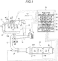
- an injector 11 which directly injects high pressure fuel accumulated in a common rail (not illustrated) into a cylinder is provided in each of cylinders of a diesel engine (hereinafter, simply referred to as an engine) 10.
- the fuel injection amount or the fuel injection timing of the injector 11 is controlled in response to an instruction signal input from an electronic controller (hereinafter, referred to as ECU) 50.
- ECU electronic controller
- An intake manifold 10A of the engine 10 is connected with an intake passage 12 which introduces fresh air therein, and an exhaust manifold 10B is connected with an exhaust passage 13 which derives an exhaust gas outside.
- An air cleaner 14, an intake air amount sensor (hereinafter, referred to as a MAF sensor) 40, a compressor 20A of a variable capacity supercharger 20, an intercooler 15, an intake throttle valve 16, and the like are provided in order from an intake upstream side in the intake passage 12.
- a turbine 20B of the variable capacity supercharger 20, an exhaust post-treatment device 30, and the like are provided in order from an exhaust upstream side in the exhaust passage 13.
- a reference numeral 41 denotes an engine speed sensor
- a reference numeral 42 denotes an accelerator opening sensor
- a reference numeral 46 denotes a boost pressure sensor.
- An EGR device 21 includes an EGR passage 22 which connects the exhaust manifold 10B and the intake manifold 10A, an EGR cooler 23 which cools an EGR gas, and an EGR valve 24 which adjusts an EGR amount.
- the exhaust post-treatment device 30 is configured such that an oxidation catalyst 31, an NOx occlusion reduction type catalyst 32, and a particulate filter (hereinafter, simply referred to as a filter) 33 are disposed in order from the exhaust upstream side in a case 30A.
- An exhaust pipe injection device 34 which injects an unburned fuel (mainly, HC) into the exhaust passage 13 in response to the instruction signal input from an ECU 50 is provided in the exhaust passage 13 on the upstream side from the oxidation catalyst 31.
- the oxidation catalyst 31 is formed by carrying an oxidation catalyst component on a ceramic carrier surface such as a honeycomb structure.
- a ceramic carrier surface such as a honeycomb structure.
- the NOx occlusion reduction type catalyst 32 is formed by carrying an alkali metal and the like on a ceramic carrier surface such as a honeycomb structure.
- the NOx occlusion reduction type catalyst 32 occludes NOx in the exhaust gas when an exhaust air fuel ratio is in a lean state, and reduces and purifies the occluded NOx by a reducing agent (HC and the like) contained in the exhaust gas when the exhaust air fuel ratio is in a rich state.
- a reducing agent HC and the like
- the filter 33 is formed such that a plurality of cells sectioned by porous partition walls are disposed in a flowing direction of the exhaust gas, and the upstream side and the downstream side of the cells are sealed alternately.
- PM in the exhaust gas is collected in a pore or a surface of the partition wall, and when the estimation amount of PM deposition reaches a predetermined amount, the so-called filter-forced regeneration is performed which combusts and removes the PM.
- the filter-forced regeneration is performed in such a manner that the unburned fuel is supplied to the oxidation catalyst 31 on the upstream side by an exhaust pipe injection or the post injection, and the temperature of the exhaust gas flowing in the filter 33 is raised to a PM combusting temperature.
- a first exhaust temperature sensor 43 is provided on the upstream side from the oxidation catalyst 31, and detects the temperature of the exhaust gas flowing in the oxidation catalyst 31.
- a second exhaust temperature sensor 44 is provided between the oxidation catalyst 31 and the NOx occlusion reduction type catalyst 32, and detects the temperature of the exhaust gas flowing in the NOx occlusion reduction type catalyst 32.
- An NOx/lambda sensor 45 is provided on the downstream side from the filter 33, and detects an NOx value and a lambda value of the exhaust gas passing through the NOx occlusion reduction type catalyst 32 (hereinafter, referred to as an excess-air-ratio).
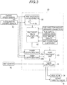
- the ECU 50 performs various controls on the engine 10 and the like, and includes a well-known CPU or a ROM, a RAM, an input port, an output port, and the like. In order to perform the various controls, the sensor values of the sensors 40 to 45 are input to the ECU 50.
- the ECU 50 includes a filter-forced regeneration controller 51, an SOx desorption treatment unit 60, an NOx desorption treatment unit 70, a MAF follow-up controller 80, an injection amount learning correction unit 90, and a MAF correction coefficient calculation unit 95 as partial functional elements.
- such functional elements are included in the ECU 50 which is an integral hardware. However, any part thereof may be provided in a separate hardware.
- the filter-forced regeneration controller 51 estimates the PM deposition amount of the filter 33 from the travel distance of the vehicle, or the differential pressure across the filter detected by a differential pressure sensor (not illustrated), and turns on a forced regeneration flag F DPF when the estimation amount of PM deposition exceeds a predetermined upper limit threshold (see time t 1 of FIG. 2 ).
- the forced regeneration flag F DPF is turned on, the instruction signal which executes the exhaust pipe injection is transmitted to the exhaust pipe injection device 34, or the instruction signal which executes the post injection is transmitted to each of the injectors 11, so that the exhaust temperature is raised to the PM combusting temperature (for example, about 550°C).
- the forced regeneration flag F DPF is turned off when the estimation amount of PM deposition is reduced to a predetermined lower limit threshold (determination threshold) indicating combusting and removing (see time t 2 of FIG. 2 ).
- the SOx desorption treatment unit 60 is an example of a regeneration treatment unit of the present invention, and executes a control (hereinafter, referred to the control as an SOx purge control) which recovers the NOx occlusion reduction type catalyst 32 from SOx-poisoning by setting the exhaust gas to a rich state so as to raise the exhaust temperature to a sulfur desorption temperature (for example, about 600°C).
- a control hereinafter, referred to the control as an SOx purge control
- FIG. 2 illustrates a timing flowchart of the SOx purge control of this embodiment.
- the SOx purge flag F SP which starts the SOx purge control is turned on simultaneously when the forced regeneration flag F DPF is turned off (see time t 2 of FIG. 2 ). Accordingly, a transition to the SOx purge control can be efficiently performed from a state where the exhaust temperature is raised by the forced regeneration of the filter 33, and the fuel consumption amount can be reduced effectively.
- the enrichment of the exhaust gas is made by using the SOx purge control, for example, in a such a manner that the SOx purge lean control that lowers the excess-air-ratio by an air-system control from a steady operating state (for example, about 1.5) to a first target excess-air-ratio (for example, about 1.3) on a lean side from a value equivalent to a theoretical air-fuel ratio (about 1.0), and the SOx purge rich control that lowers the excess-air-ratio by the injection control from the first target excess-air-ratio to a second target excess-air-ratio on a rich side (for example, about 0.9) are used in combination.
- the SOx purge lean control that lowers the excess-air-ratio by an air-system control from a steady operating state (for example, about 1.5) to a first target excess-air-ratio (for example, about 1.3) on a lean side from a value equivalent to a theoretical air-fuel ratio (about 1.0)
- FIG. 3 is a block diagram illustrating a setting process of a MAF target value MAF SPL Trgt at the time of the SOx purge lean control.
- a first target excess-air-ratio setting map 61 is a map based on an engine speed Ne and an accelerator opening degree Q (fuel injection amount of the engine 10).
- An excess-air-ratio target value ⁇ SPL Trgt (first target excess-air-ratio) at the time of the SOx purge lean control corresponding to the engine speed Ne and the accelerator opening degree Q is set based on an experiment and the like, in advance.
- the excess-air-ratio target value ⁇ SPL Trgt at the time of the SOx purge lean control is read from the first target excess-air-ratio setting map 61 by using the engine speed Ne and the accelerator opening degree Q as input signals, and is input to a MAF target value calculation unit 62.
- the MAF target value MAF SPL Trgt at the time of the SOx purge lean control is calculated based on the following Equation (1).
- MAF SPL Trgt ⁇ SPL Trgt ⁇ Q fnl corrd ⁇ Ro Fuel ⁇ AFR sto / Maf corr
- Equation (1) Q fnl corrd indicates a learning-corrected (to be described later) fuel injection amount (excluding the post injection), Ro Fuel indicates a fuel specific gravity, AFR sto indicates a theoretical air-fuel ratio, and Maf corr indicates a MAF correction coefficient (to be described later).
- the MAF target value MAF SPL Trgt calculated by the MAF target value calculation unit 62 is input to a ramp treatment unit 63 when the SOx purge flag F SP is turned on (see time t 2 of FIG. 2 ).
- the ramp treatment unit 63 reads a ramp coefficient from ramp coefficient maps 63A and 63B by using the engine speed Ne and the accelerator opening degree Q as input signals, and inputs a MAF target ramp value MAF SPL Trgt Ramp , in which the ramp coefficient is added, to a valve controller 64.
- the valve controller 64 executes a feedback control that throttles the intake throttle valve 16 to the shutting side and opens the EGR valve 24 to the open side such that an actual MAF value MAF Act input from the MAF sensor 40 becomes the MAF target ramp value MAF SPL Trgt Ramp ,
- the MAF target value MAF SPL Trgt is set based on the excess-air-ratio target value ⁇ SPL Trgt read from the first target excess-air-ratio setting map 61 and the fuel injection amount of the injector 11, and an air system operation is feedback-controlled based on the MAF target value MAF SPL Trgt . Accordingly, without providing the lambda sensor on the upstream side of the NOx occlusion reduction type catalyst 32 or without using a sensor value of the lambda sensor even when the lambda sensor is provided on the upstream side of the NOx occlusion reduction type catalyst 32, the exhaust gas can be effectively lowered to the desired excess-air-ratio required for the SOx purge lean control.
- the MAF target value MAF SPL Trgt can be set by a feed-forward control to effectively exclude influence such as the aged deterioration, the property change, or the individual difference of the injector 11.
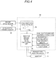
- FIG. 4 is a block diagram illustrating a setting process of the target injection amount Q SPR Trgt (injection amount per unit of time) of the exhaust pipe injection or the post injection in the SOx purge rich control.
- a second target excess-air-ratio setting map 65 is a map based on the engine speed Ne and the accelerator opening degree Q.
- the excess-air-ratio target value ⁇ SPR Trgt (second target excess-air-ratio) at the time of the SOx purge rich control corresponding to the engine speed Ne and the accelerator opening degree Q is set based on an experiment and the like, in advance.
- the excess-air-ratio target value ⁇ SPR Trgt at the time of the SOx purge rich control is read from the second target excess-air-ratio setting map 65 by using the engine speed Ne and the accelerator opening degree Q as input signals, and is input to an injection amount target value calculating unit 66.
- the target injection amount Q SPR Trgt at the time of the SOx purge rich control is calculated based on the following Equation (2).
- Q SPR Trgt MAF SPL Trgt ⁇ Maf corr / ⁇ SPL Target ⁇ Ro Fuel ⁇ AFR sto ⁇ Q fnl corrd
- MAF SPL Trgt is a MAF target value at the time of a lean SOx purge, and is input from the above-described MAF target value calculation unit 62.
- Q fnlRaw corrd indicates a learning-corrected (to be described later) fuel injection amount (excluding the post injection) before a MAF follow-up control is applied thereto
- Ro Fuel indicates a fuel specific gravity
- AFR sto indicates a theoretical air-fuel ratio
- Maf corr indicates a MAF correction coefficient (to be described later).
- the target injection amount Q SPR Trgt calculated by the injection amount target value calculating unit 66 is transmitted as the injection instruction signal to the exhaust pipe injection device 34 or the injector 11.
- the target injection amount Q SPR Trgt is set based on the excess-air-ratio target value ⁇ SPR Trgt read from the second target excess-air-ratio setting map 65 and the fuel injection amount of the injector 11. Accordingly, without providing the lambda sensor on the upstream side of the NOx occlusion reduction type catalyst 32 or without using a sensor value of the lambda sensor even when the lambda sensor is provided on the upstream side of the NOx occlusion reduction type catalyst 32, the exhaust gas can be effectively lowered to the desired excess-air-ratio required for the SOx purge rich control.
- the target injection amount Q SPR Trgt can be set by the feed-forward control to effectively exclude influence such as the aged deterioration, the property change, or the like of the injector 11.
- the temperature of the exhaust gas (hereinafter, referred to as a catalyst temperature) flowing in the NOx occlusion reduction type catalyst 32 during the SOx purge control is controlled by alternately switching on and off (rich and lean) of the SOx purge rich flag F SPR which executes the exhaust pipe injection or the post injection.
- F SPR 1
- the catalyst temperature is raised by the exhaust pipe injection or the post injection (hereinafter, referred to a time thereof as an injection time T F INJ ).
- the SOx purge rich flag F SPR is turned off, the catalyst temperature is lowered by the stop of the exhaust pipe injection or the post injection (hereinafter, referred to a time thereof as an interval T F INT ).
- the injection time T F INJ is set by reading a value corresponding to the engine speed Ne and the accelerator opening degree Q from an injection time setting map (not illustrated) created through an experiment and the like, in advance.
- the injection time setting map the injection time required to reliably lower the excess-air-ratio of the exhaust gas obtained by an experiment and the like, in advance to the second target excess-air-ratio is set in response to the operating state of the engine 10.
- the interval T F INT is set through a feedback control.
- the interval T F INT is processed by a PID control configured by a proportional control that changes an input signal in proportion to the deviation ⁇ T between a target catalyst temperature and an estimated catalyst temperature when the SOx purge rich flag F SPR is turned off, an integral control that changes the input signal in proportion to a time integral value of the deviation ⁇ T, and a differential control that changes the input signal in proportion to a time differential value of the deviation ⁇ T.
- the target catalyst temperature is set to such a degree as to desorb SOx from the NOx occlusion reduction type catalyst 32.
- the estimated catalyst temperature may be estimated, for example, based on an inlet temperature of the oxidation catalyst 31 detected by the first exhaust temperature sensor 43, an exothermic reaction inside the oxidation catalyst 31 and the NOx occlusion reduction type catalyst 32, and the like.
- the SOx purge control starts from the SOx purge rich control without performing the SOx purge lean control, and thus a prompt transition to the SOx purge control can be performed and the fuel consumption amount can be reduced without lowering the exhaust temperature raised by the filter-forced regeneration.
- the SOx purge rich flag F SPR is turned off with the lapse of the injection time T F INJ 1 .
- the SOx purge rich flag F SPR is turned off until the interval T F INT 1 set by the PID control elapses (see times t 2 to t 3 of FIG. 5 ).
- the SOx purge rich flag F SPR is turned on with the lapse of the interval T F INT 1 , the exhaust pipe injection or the post injection according to the injection time T F INJ 2 is executed again (see time from t 3 to t 4 of FIG. 5 ).
- the injection time T F INJ in which the catalyst temperature is raised and the excess-air-ratio is lowered to the second target excess-air-ratio is set from the map based on the operating state of the engine 10, and the interval T F INT in which the catalyst temperature is lowered is treated by the PID control. Accordingly, the catalyst temperature in the SOx purge control is effectively kept in the desired temperature range required for a purge, and the excess-air-ratio can be reliably lowered to a target excess ratio.
- the SOx purge control is terminated by turning off the SOx purge flag F SP (see time t 4 of FIG. 2 and time t n of FIG. 5 ).
- the upper limit of the cumulative injection amount and the elapsed time is set in the termination condition of the SOx purge control, so that it can be effectively suppressed that the fuel consumption amount is excessive in a case where the SOx purge does not progress due to the lowering of the exhaust temperature and the like.
- the NOx desorption treatment unit 70 is an example of the regeneration treatment unit of the present invention.
- the NOx desorption treatment unit 70 executes a control that recovers the NOx occlusion capacity of the NOx occlusion reduction type catalyst 32 by detoxifying the NOx, which is occluded in the NOx occlusion reduction type catalyst 32 when the exhaust gas is under a rich atmosphere, by reducing and purifying, and then discharging the NOx (hereinafter, referred to the control as an NOx purge control).
- the NOx purge flag F NP which starts the NOx purge control is turned on when an NOx discharging amount per unit of time is estimated from the operating state of the engine 10 and then an estimated accumulated value ⁇ NOx calculated by accumulating the NOx discharging amounts exceeds the predetermined threshold (see time t 1 of FIG. 6 ).
- the NOx purge flag F NP is turned on in a case where an NOx purification rate of the NOx occlusion reduction type catalyst 32 is calculated from the NOx discharging amount on the catalyst upstream side estimated from the operating state of the engine 10 and then an NOx amount on the catalyst downstream side detected by the NOx/lambda sensor 45, and the NOx purification rate is lower than the predetermined determination threshold.
- the enrichment of the exhaust gas is made by using the NOx purge control, for example, in such a manner that the NOx purge lean control that lowers the excess-air-ratio by an air-system control from a steady operating state (for example, about 1.5) to a third target excess-air-ratio (for example, about 1.3) on a lean side from a value equivalent to a theoretical air-fuel ratio (about 1.0), and the NOx purge rich control that lowers the excess-air-ratio by the injection control from a fourth target excess-air-ratio to the second target excess-air-ratio on a rich side (for example, about 0.9) are used in combination.
- the detail description will be given about the NOx purge lean control and the NOx purge rich control.
- FIG. 7 is a block diagram illustrating a setting process of the MAF target value MAF NPL Trgt at the time of the NOx purge lean control.
- a third target excess-air-ratio setting map 71 is a map based on the engine speed Ne and the accelerator opening degree Q.
- the excess-air-ratio target value ⁇ NPL Trgt (third target excess-air-ratio) at the time of the NOx purge lean control corresponding to the engine speed Ne and the accelerator opening degree Q is set based on an experiment and the like, in advance.
- the excess-air-ratio target value ⁇ NPL Trgt at the time of the NOx purge lean control is read from the third target excess-air-ratio setting map 71 by using the engine speed Ne and the accelerator opening degree Q as input signals, and is input to the MAF target value calculation unit 72.
- the MAF target value MAF NPL Trgt at time of the NOx purge lean control is calculated based on the following Equation (3).
- MAF SPL Trgt ⁇ NPL Trgt ⁇ Q fnl corrd ⁇ Ro Fuel ⁇ AFR sto / Maf corr
- Equation (3) Q fnl corrd indicates a learning-corrected (to be described later) fuel injection amount (excluding the post injection), Ro Fuel indicates a fuel specific gravity, AFR sto indicates a theoretical air-fuel ratio, and Maf corr indicates a MAF correction coefficient (to be described later).
- the MAF target value MAF NPL Trgt calculated by the MAF target value calculation unit 72 is input to a ramp treatment unit 73 when the NOx purge flag F SP is turned on (see time t 1 of FIG. 6 ).
- the ramp treatment unit 73 reads a ramp coefficient from ramp coefficient maps 73A and 73B by using the engine speed Ne and the accelerator opening degree Q as input signals, and inputs a MAF target ramp value MAF NPL Trgt Ramp , in which the ramp coefficient is added, to a valve controller 74.
- the valve controller 74 executes a feedback control that throttles the intake throttle valve 16 to the shutting side and opens the EGR valve 24 to the open side such that the actual MAF value MAF Act input from the MAF sensor 40 becomes the MAF target ramp value MAF NPL Trgt Ramp .
- the MAF target value MAF NPL Trgt is set based on the excess-air-ratio target value ⁇ NPL Trgt read from the third target excess-air-ratio setting map 71 and the fuel injection amount of the injector 11, and an air system operation is feedback-controlled based on the MAF target value MAF NPL Trgt . Accordingly, without providing the lambda sensor on the upstream side of the NOx occlusion reduction type catalyst 32 or without using a sensor value of the lambda sensor even when the lambda sensor is provided on the upstream side of the NOx occlusion reduction type catalyst 32, the exhaust gas can be effectively lowered to the desired excess-air-ratio required for the NOx purge lean control.
- the MAF target value MAF NPL Trgt can be set by a feed-forward control to effectively exclude influence such as the aged deterioration, the property change, or the like of the injector 11.
- FIG. 8 is a block diagram illustrating a setting process of the target injection amount Q NPR Trgt (injection amount per unit of time) of the exhaust pipe injection or the post injection in the NOx purge rich control.
- a fourth target excess-air-ratio setting map 75 is a map based on the engine speed Ne and the accelerator opening degree Q.
- the excess-air-ratio target value ⁇ NPR Trgt (fourth target excess-air-ratio) at the time of the NOx purge rich control corresponding to the engine speed Ne and the accelerator opening degree Q is set based on an experiment and the like, in advance.
- the excess-air-ratio target value ⁇ NPR Trgt at the time of the NOx purge rich control is read from the fourth target excess-air-ratio setting map 75 by using the engine speed Ne and the accelerator opening degree Q as input signals, and is input to an injection amount target value calculating unit 76.
- the target injection amount Q NPR Trgt at the time of the NOx purge rich control is calculated based on the following Equation (4).
- Q NPR Trgt MAF NPL Trgt ⁇ Maf corr / ⁇ NPR Target ⁇ Ro Fuel ⁇ AFR sto ⁇ Q fnl corrd
- MAF NPL Trgt is a MAF target value at the time of a lean NOx purge, and is input from the above-described MAF target value calculation unit 72.
- Q fnlRaw corrd indicates a learning-corrected (to be described later) fuel injection amount (excluding the post injection) before a MAF follow-up control is applied thereto
- Ro Fuel indicates a fuel specific gravity
- AFR sto indicates a theoretical air-fuel ratio
- Maf corr indicates a MAF correction coefficient (to be described later).
- the target injection amount Q NPR Trgt calculated by the injection amount target value calculating unit 76 is transmitted as the injection instruction signal to the exhaust pipe injection device 34 or the injector 11 (time t 1 of FIG. 6 ).
- the transmission of the injection instruction signal is continued until the NOx purge flag F NP is turned off (time t 2 of FIG. 6 ) by the termination determination of the NOx purge control (to be described later).
- the target injection amount Q NPR Trgt is set based on the excess-air-ratio target value ⁇ NPR Trgt read from the fourth target excess-air-ratio setting map 75 and the fuel injection amount of the injector 11. Accordingly, without providing the lambda sensor on the upstream side of the NOx occlusion reduction type catalyst 32 or without using a sensor value of the lambda sensor even when the lambda sensor is provided on the upstream side of the NOx occlusion reduction type catalyst 32, the exhaust gas can be effectively lowered to the desired excess-air-ratio required for the NOx purge rich control.
- the target injection amount Q NPR Trgt can be set by the feed-forward control to effectively exclude influence such as the aged deterioration, the property change, or the like of the injector 11.
- the ECU 50 feedback-controls the opening degree of the intake throttle valve 16 or the EGR valve 24 based on a sensor value of the MAF sensor 40.
- the ECU 50 feedback-controls a supercharging pressure by the variable capacity supercharger 20 based on a sensor value of the boost pressure sensor 46 (hereinafter, referred to the area as a boosting pressure FB control area).
- the excess-air-ratio may not be lowered to the fourth target excess-air-ratio (excess-air-ratio target value ⁇ NPR Trgt ) required for the NOx purge.
- the NOx desorption treatment unit 70 of this embodiment prohibits the NOx purge lean control to adjust the opening degree of the intake throttle valve 16 or the EGR valve 24, and lowers the excess-air-ratio to the fourth target excess-air-ratio (excess-air-ratio target value ⁇ NPR Trgt ) only through the exhaust pipe injection or the post injection. Accordingly, even in the boosting pressure FB control area, the NOx purge can be performed reliably.
- the MAF target value set based on the operating state of the engine 10 may be applied to the MAF target value MAF NPL Trgt of the above-described Equation (4).
- the NOx purge control is terminated by turning off the NOx purge flag F NP (see time t 2 of FIG. 6 ).
- the upper limit of the cumulative injection amount and the elapsed time is set in the termination condition of the NOx purge control so that it can be reliably suppressed that the fuel consumption amount is excessive in a case where the NOx purge does not succeed due to the lowering of the exhaust temperature and the like.
- the MAF follow-up controller 80 executes a control to correct the fuel injection timing and the fuel injection amount of the injector 11 in response to a MAF change (hereinafter, referred to the control as a MAF follow-up control).
- the injection amount learning correction unit 90 includes a learning correction coefficient calculating unit 91 and an injection amount correcting unit 92.
- the learning correction coefficient calculating unit 91 calculates a learning correction coefficient F Corr of the fuel injection amount based on an error ⁇ between an actual lambda value ⁇ Act detected by the NOx/lambda sensor 45 at the time of a lean operation of the engine 10 and an estimated lambda value ⁇ Est .
- a learning correction coefficient F Corr of the fuel injection amount based on an error ⁇ between an actual lambda value ⁇ Act detected by the NOx/lambda sensor 45 at the time of a lean operation of the engine 10 and an estimated lambda value ⁇ Est .
- the error ⁇ occurs between the actual lambda value ⁇ Act and the estimated lambda value ⁇ Est .
- the error can be assumed to result from a difference between an instructed injection amount and an actual injection amount in the injector 11.
- the calculation process of the learning correction coefficient performed by the learning correction coefficient calculating unit 91 using the error ⁇ will be described based on the flow of FIG. 10 .
- Step S300 it is determined based on the engine speed Ne and the accelerator opening degree Q whether the engine 10 is in a lean operating state. If the engine 10 is in the lean operating state, the procedure proceeds to Step S310 in order to start the calculation of the learning correction coefficient.
- the estimated lambda value ⁇ Est is estimated and calculated from the operating state of the engine 10 based on the engine speed Ne or the accelerator opening degree Q.
- the correction sensitivity coefficient K 2 is read from a correction sensitivity coefficient map 91A illustrated in FIG. 9 by using the actual lambda value ⁇ Act detected by the NOx/lambda sensor 45 as an input signal.
- Step S320 it is determined whether an absolute value
- Step S330 it is determined whether a learning prohibition flag F Pro is turned off.
- a case where the time change amount is larger than the predetermined threshold may be determined as the transient operating state.
- Step S340 a learning value map 91B (see FIG. 9 ) based on the engine speed Ne and the accelerator opening degree Q is renewed to the learning value F CorrAdpt calculated in Step S310. More specifically, a plurality of learning areas sectioned in response to the engine speed Ne and the accelerator opening degree Q are set on the learning value map 91B. Preferably, such learning areas are set such that the range thereof is narrower as the area is used more frequently, and the range thereof is wider as the area is used less frequently. Accordingly, in the frequently used area, a learning accuracy can be improved, and in the less-frequently used area, non-learning can be effectively suppressed.
- the learning correction coefficient F Corr is input to the injection amount correcting unit 92 illustrated in FIG. 9 .
- the injection amount correcting unit 92 executes the correction of the fuel injection amount by multiplying respective basic injection amounts of a pilot injection Q Pilot , a pre-injection Q Pre , a main injection Q Main , an after injection Q After , by a post injection Q Post by the learning correction coefficient F Corr .
- the MAF correction coefficient calculation unit 95 calculates a MAF correction coefficient Maf corr used to set the MAF target value MAF SPL Trgt or the target injection amount Q SPR Trgt at the time of the SOx purge control and to set the MAF target value MAF NPL Trgt or the target injection amount Q NPR Trgt at the time of the NOx purge control.
- the fuel injection amount of the injector 11 is corrected based on the error ⁇ , between the actual lambda value ⁇ Act detected by the NOx/lambda sensor 45 and the estimated lambda value ⁇ Est .
- the lambda is a ratio of air and fuel
- a factor of the error ⁇ is not necessarily limited to the effect of the difference between the instructed injection amount and the actual injection amount in the injector 11. That is, the error ⁇ , of the lambda may be affected by an error of the MAF sensor 40 as well as that of the injector 11.
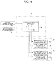
- FIG. 11 is a block diagram illustrating a setting process of the MAF correction coefficient Maf corr performed by the MAF correction coefficient calculation unit 95.
- a correction coefficient setting map 96 is a map based on the engine speed Ne and the accelerator opening degree Q, and the MAF correction coefficient Maf corr indicating the sensor property of the MAF sensor 40 corresponding to the engine speed Ne and the accelerator opening degree Q is set based on an experiment and the like, in advance.
- the MAF correction coefficient calculation unit 95 reads the MAF correction coefficient Maf corr from the correction coefficient setting map 96 by using the engine speed Ne and the accelerator opening degree Q as input signals, and transmits the MAF correction coefficient Maf corr to the MAF target value calculation units 62 and 72 and the injection amount target value calculating units 66 and 76. Accordingly, the sensor property of the MAF sensor 40 can be effectively reflected to set the MAF target value MAF SPL Trgt or the target injection amount Q SPR Trgt at the time of the SOx purge control and the MAF target value MAF NPL Trgt or the target injection amount Q NPR Trgt at the time of the NOx purge control.
Landscapes
- Engineering & Computer Science (AREA)
- Chemical & Material Sciences (AREA)
- Combustion & Propulsion (AREA)
- Mechanical Engineering (AREA)
- General Engineering & Computer Science (AREA)
- Chemical Kinetics & Catalysis (AREA)
- Health & Medical Sciences (AREA)
- Toxicology (AREA)
- Exhaust Gas After Treatment (AREA)
- Electrical Control Of Air Or Fuel Supplied To Internal-Combustion Engine (AREA)
- Exhaust Gas Treatment By Means Of Catalyst (AREA)
- Processes For Solid Components From Exhaust (AREA)
Abstract
Description
- The present invention relates to an exhaust purification system.
- In the background art, an NOx occlusion reduction type catalyst is known as a catalyst which reduces and purifies a nitrogen compound (NOx) in an exhaust gas discharged from an internal combustion engine. When the exhaust gas is under a lean atmosphere, the NOx occlusion reduction type catalyst occludes the NOx contained in the exhaust gas. When the exhaust gas is under a rich atmosphere, the NOx occlusion reduction type catalyst detoxifies the occluded NOx through reducing and purifying by hydrocarbon contained in the exhaust gas, and discharges the NOx.
- In the NOx occlusion reduction type catalyst, a sulfur oxide contained in the exhaust gas (hereinafter, referred to as SOx) is also occluded. There is a problem that when the SOx occlusion amount increases, the NOx purification capacity of the NOx occlusion reduction type catalyst is reduced. For this reason, in a case where an SOx occlusion amount reaches a predetermined amount, in order that the SOx is desorbed from the NOx occlusion reduction type catalyst to recover the NOx occlusion reduction type catalyst from S-poisoning, it is necessary to regularly perform the so-called SOx purge in which an unburned fuel is supplied to an upstream-side oxidation catalyst by the post injection or the exhaust pipe injection to raise an exhaust temperature to an SOx desorption temperature (for example, see Patent Literature 1).
-
- [Patent Literature 1]: Japanese Unexamined Patent Application Publication No.
2009-047086 - [Patent Literature 2]: Japanese Unexamined Patent Application Publication No.
2007-315225 - [Patent Literature 3]: Japanese Unexamined Patent Application Publication No.
2009-115038 - A method, in which a rich control to set an exhaust air fuel ratio to a rich state so as to raise the exhaust temperature and a lean control to set an exhaust air fuel ratio to a lean state so as to lower the exhaust temperature are alternately executed, is known as a method in which a catalyst temperature at the time of the SOx purge is kept in a predetermined temperature range (for example, see Patent Literature 1). However, if respective execution periods of the rich control and the lean control are not optimally controlled, the exhaust temperature is excessively raised during the rich control, which may cause heat deterioration of the NOx occlusion reduction type catalyst. In addition, when the exhaust temperature is excessively lowered during the lean control, the catalyst temperature may be hardly stabilized to the SOx desorption temperature.
- The disclosed system is made to effectively suppress that a catalyst temperature at the time of an SOx purge is excessively raised or lowered.
- The disclosed system is an exhaust purification system including an NOx reduction type catalyst, which is provided in an exhaust system of an internal combustion engine and reduces and purifies NOx in an exhaust gas; a temperature acquisition unit, which acquires a catalyst temperature of the NOx reduction type catalyst; and a regeneration treatment unit, which executes a catalyst regeneration to recover an NOx purification capacity of the NOx reduction type catalyst, wherein the regeneration treatment unit alternately executes a rich control, in which an exhaust air fuel ratio is set to a rich state so as to raise the NOx reduction type catalyst to a predetermined target temperature, and a lean control, in which the exhaust air fuel ratio is set to a lean state so as to lower a temperature of the NOx reduction type catalyst, and sets an execution period of the lean control by a PID control, based on a deviation between a catalyst temperature acquired by the temperature acquisition unit during the previous rich control and the target temperature.
-
-
FIG. 1 is an entire configuration diagram illustrating an exhaust purification system according to this embodiment. -
FIG. 2 is a timing chart for describing an SOx purge control according to this embodiment. -
FIG. 3 is a block diagram illustrating a setting process of a MAF target value at the time of an SOx purge lean control according to this embodiment. -
FIG. 4 is a block diagram illustrating a setting process of a target injection amount at the time of an SOx purge rich control according to this embodiment. -
FIG. 5 is a timing chart for describing a catalyst temperature adjustment control in the SOx purge control according to this embodiment. -
FIG. 6 is a timing chart for describing an NOx purge control according to this embodiment. -
FIG. 7 is a block diagram illustrating a setting process of a MAF target value at the time of an NOx purge lean control according to this embodiment. -
FIG. 8 is a block diagram illustrating a setting process of a target injection amount at the time of an NOx purge rich control according to this embodiment. -
FIG. 9 is a block diagram illustrating a process of an injection amount learning correction of an injector according to this embodiment. -
FIG. 10 is a flow diagram for describing a calculation process of a learning correction coefficient according to this embodiment. -
FIG. 11 is a block diagram illustrating a setting process of a MAF correction coefficient according to this embodiment. - Hereinafter, an exhaust purification system according to one embodiment of the present invention will be described based on accompanying drawings.
- As illustrated in
FIG. 1 , aninjector 11 which directly injects high pressure fuel accumulated in a common rail (not illustrated) into a cylinder is provided in each of cylinders of a diesel engine (hereinafter, simply referred to as an engine) 10. The fuel injection amount or the fuel injection timing of theinjector 11 is controlled in response to an instruction signal input from an electronic controller (hereinafter, referred to as ECU) 50. - An intake manifold 10A of the
engine 10 is connected with anintake passage 12 which introduces fresh air therein, and anexhaust manifold 10B is connected with anexhaust passage 13 which derives an exhaust gas outside. Anair cleaner 14, an intake air amount sensor (hereinafter, referred to as a MAF sensor) 40, a compressor 20A of a variable capacity supercharger 20, anintercooler 15, anintake throttle valve 16, and the like are provided in order from an intake upstream side in theintake passage 12. A turbine 20B of the variable capacity supercharger 20, anexhaust post-treatment device 30, and the like are provided in order from an exhaust upstream side in theexhaust passage 13. InFIG. 1 , areference numeral 41 denotes an engine speed sensor, areference numeral 42 denotes an accelerator opening sensor, and areference numeral 46 denotes a boost pressure sensor. - An
EGR device 21 includes an EGRpassage 22 which connects theexhaust manifold 10B and the intake manifold 10A, an EGR cooler 23 which cools an EGR gas, and anEGR valve 24 which adjusts an EGR amount. - The
exhaust post-treatment device 30 is configured such that anoxidation catalyst 31, an NOx occlusionreduction type catalyst 32, and a particulate filter (hereinafter, simply referred to as a filter) 33 are disposed in order from the exhaust upstream side in acase 30A. An exhaustpipe injection device 34 which injects an unburned fuel (mainly, HC) into theexhaust passage 13 in response to the instruction signal input from anECU 50 is provided in theexhaust passage 13 on the upstream side from theoxidation catalyst 31. - For example, the
oxidation catalyst 31 is formed by carrying an oxidation catalyst component on a ceramic carrier surface such as a honeycomb structure. When an unburned fuel is supplied by the post injection of the exhaustpipe injection device 34 or theinjector 11, theoxidation catalyst 31 oxidizes the unburned fuel to raise the exhaust temperature. - For example, the NOx occlusion
reduction type catalyst 32 is formed by carrying an alkali metal and the like on a ceramic carrier surface such as a honeycomb structure. The NOx occlusionreduction type catalyst 32 occludes NOx in the exhaust gas when an exhaust air fuel ratio is in a lean state, and reduces and purifies the occluded NOx by a reducing agent (HC and the like) contained in the exhaust gas when the exhaust air fuel ratio is in a rich state. - For example, the
filter 33 is formed such that a plurality of cells sectioned by porous partition walls are disposed in a flowing direction of the exhaust gas, and the upstream side and the downstream side of the cells are sealed alternately. In thefilter 33, PM in the exhaust gas is collected in a pore or a surface of the partition wall, and when the estimation amount of PM deposition reaches a predetermined amount, the so-called filter-forced regeneration is performed which combusts and removes the PM. The filter-forced regeneration is performed in such a manner that the unburned fuel is supplied to theoxidation catalyst 31 on the upstream side by an exhaust pipe injection or the post injection, and the temperature of the exhaust gas flowing in thefilter 33 is raised to a PM combusting temperature. - A first
exhaust temperature sensor 43 is provided on the upstream side from theoxidation catalyst 31, and detects the temperature of the exhaust gas flowing in theoxidation catalyst 31. A secondexhaust temperature sensor 44 is provided between theoxidation catalyst 31 and the NOx occlusionreduction type catalyst 32, and detects the temperature of the exhaust gas flowing in the NOx occlusionreduction type catalyst 32. An NOx/lambda sensor 45 is provided on the downstream side from thefilter 33, and detects an NOx value and a lambda value of the exhaust gas passing through the NOx occlusion reduction type catalyst 32 (hereinafter, referred to as an excess-air-ratio). - The ECU 50 performs various controls on the
engine 10 and the like, and includes a well-known CPU or a ROM, a RAM, an input port, an output port, and the like. In order to perform the various controls, the sensor values of thesensors 40 to 45 are input to theECU 50. The ECU 50 includes a filter-forcedregeneration controller 51, an SOxdesorption treatment unit 60, an NOxdesorption treatment unit 70, a MAF follow-up controller 80, an injection amountlearning correction unit 90, and a MAF correctioncoefficient calculation unit 95 as partial functional elements. In description, such functional elements are included in the ECU 50 which is an integral hardware. However, any part thereof may be provided in a separate hardware. - The filter-forced
regeneration controller 51 estimates the PM deposition amount of thefilter 33 from the travel distance of the vehicle, or the differential pressure across the filter detected by a differential pressure sensor (not illustrated), and turns on a forced regeneration flag FDPF when the estimation amount of PM deposition exceeds a predetermined upper limit threshold (see time t1 ofFIG. 2 ). When the forced regeneration flag FDPF is turned on, the instruction signal which executes the exhaust pipe injection is transmitted to the exhaustpipe injection device 34, or the instruction signal which executes the post injection is transmitted to each of theinjectors 11, so that the exhaust temperature is raised to the PM combusting temperature (for example, about 550°C). The forced regeneration flag FDPF is turned off when the estimation amount of PM deposition is reduced to a predetermined lower limit threshold (determination threshold) indicating combusting and removing (see time t2 ofFIG. 2 ). For example, the determination threshold in which the forced regeneration flag FDPF is turned off may be set based on the upper limit elapsed time or the upper limit cumulative injection amount from the start (FDPF = 1) of the filter-forced regeneration. - The SOx
desorption treatment unit 60 is an example of a regeneration treatment unit of the present invention, and executes a control (hereinafter, referred to the control as an SOx purge control) which recovers the NOx occlusionreduction type catalyst 32 from SOx-poisoning by setting the exhaust gas to a rich state so as to raise the exhaust temperature to a sulfur desorption temperature (for example, about 600°C). -
FIG. 2 illustrates a timing flowchart of the SOx purge control of this embodiment. As illustrated inFIG. 2 , the SOx purge flag FSP which starts the SOx purge control is turned on simultaneously when the forced regeneration flag FDPF is turned off (see time t2 ofFIG. 2 ). Accordingly, a transition to the SOx purge control can be efficiently performed from a state where the exhaust temperature is raised by the forced regeneration of thefilter 33, and the fuel consumption amount can be reduced effectively. - In this embodiment, the enrichment of the exhaust gas is made by using the SOx purge control, for example, in a such a manner that the SOx purge lean control that lowers the excess-air-ratio by an air-system control from a steady operating state (for example, about 1.5) to a first target excess-air-ratio (for example, about 1.3) on a lean side from a value equivalent to a theoretical air-fuel ratio (about 1.0), and the SOx purge rich control that lowers the excess-air-ratio by the injection control from the first target excess-air-ratio to a second target excess-air-ratio on a rich side (for example, about 0.9) are used in combination. Hereinafter, a detail description will be given about the SOx purge lean control and the SOx purge rich control.
-
FIG. 3 is a block diagram illustrating a setting process of a MAF target value MAFSPL Trgt at the time of the SOx purge lean control. A first target excess-air-ratio setting map 61 is a map based on an engine speed Ne and an accelerator opening degree Q (fuel injection amount of the engine 10). An excess-air-ratio target value λSPL Trgt (first target excess-air-ratio) at the time of the SOx purge lean control corresponding to the engine speed Ne and the accelerator opening degree Q is set based on an experiment and the like, in advance. - First, the excess-air-ratio target value λSPL Trgt at the time of the SOx purge lean control is read from the first target excess-air-
ratio setting map 61 by using the engine speed Ne and the accelerator opening degree Q as input signals, and is input to a MAF targetvalue calculation unit 62. In addition, in the MAF targetvalue calculation unit 62, the MAF target value MAFSPL Trgt at the time of the SOx purge lean control is calculated based on the following Equation (1).
- In Equation (1), Qfnl corrd indicates a learning-corrected (to be described later) fuel injection amount (excluding the post injection), RoFuel indicates a fuel specific gravity, AFRsto indicates a theoretical air-fuel ratio, and Mafcorr indicates a MAF correction coefficient (to be described later).
- The MAF target value MAFSPL Trgt calculated by the MAF target
value calculation unit 62 is input to aramp treatment unit 63 when the SOx purge flag FSP is turned on (see time t2 ofFIG. 2 ). Theramp treatment unit 63 reads a ramp coefficient fromramp coefficient maps valve controller 64. - The
valve controller 64 executes a feedback control that throttles theintake throttle valve 16 to the shutting side and opens theEGR valve 24 to the open side such that an actual MAF value MAFAct input from theMAF sensor 40 becomes the MAF target ramp value MAFSPL Trgt Ramp, - In this manner, in this embodiment, the MAF target value MAFSPL Trgt is set based on the excess-air-ratio target value λSPL Trgt read from the first target excess-air-
ratio setting map 61 and the fuel injection amount of theinjector 11, and an air system operation is feedback-controlled based on the MAF target value MAFSPL Trgt. Accordingly, without providing the lambda sensor on the upstream side of the NOx occlusionreduction type catalyst 32 or without using a sensor value of the lambda sensor even when the lambda sensor is provided on the upstream side of the NOx occlusionreduction type catalyst 32, the exhaust gas can be effectively lowered to the desired excess-air-ratio required for the SOx purge lean control. - When the fuel injection amount Qfnl corrd after the learning correction is used as the fuel injection amount of the
injector 11, the MAF target value MAFSPL Trgt can be set by a feed-forward control to effectively exclude influence such as the aged deterioration, the property change, or the individual difference of theinjector 11. - When the ramp coefficient set in response to the operating state of the
engine 10 is added to the MAF target value MAFSPL Trgt, the deterioration of the drivability and the like caused by the misfire or the torque fluctuation of theengine 10 due to the rapid change of an intake air amount can be effectively suppressed. -
FIG. 4 is a block diagram illustrating a setting process of the target injection amount QSPR Trgt (injection amount per unit of time) of the exhaust pipe injection or the post injection in the SOx purge rich control. A second target excess-air-ratio setting map 65 is a map based on the engine speed Ne and the accelerator opening degree Q. The excess-air-ratio target value λSPR Trgt (second target excess-air-ratio) at the time of the SOx purge rich control corresponding to the engine speed Ne and the accelerator opening degree Q is set based on an experiment and the like, in advance. - First, the excess-air-ratio target value λSPR Trgt at the time of the SOx purge rich control is read from the second target excess-air-
ratio setting map 65 by using the engine speed Ne and the accelerator opening degree Q as input signals, and is input to an injection amount targetvalue calculating unit 66. In addition, in the injection amount targetvalue calculating unit 66, the target injection amount QSPR Trgt at the time of the SOx purge rich control is calculated based on the following Equation (2).
- In Equation (2), MAFSPL Trgt is a MAF target value at the time of a lean SOx purge, and is input from the above-described MAF target
value calculation unit 62. QfnlRaw corrd indicates a learning-corrected (to be described later) fuel injection amount (excluding the post injection) before a MAF follow-up control is applied thereto, RoFuel indicates a fuel specific gravity, and AFRsto indicates a theoretical air-fuel ratio, and Maf corr indicates a MAF correction coefficient (to be described later). - When the SOx purge rich flag FSPR (to be described later) is turned on, the target injection amount QSPR Trgt calculated by the injection amount target
value calculating unit 66 is transmitted as the injection instruction signal to the exhaustpipe injection device 34 or theinjector 11. - In this manner, in this embodiment, the target injection amount QSPR Trgt is set based on the excess-air-ratio target value λSPR Trgt read from the second target excess-air-
ratio setting map 65 and the fuel injection amount of theinjector 11. Accordingly, without providing the lambda sensor on the upstream side of the NOx occlusionreduction type catalyst 32 or without using a sensor value of the lambda sensor even when the lambda sensor is provided on the upstream side of the NOx occlusionreduction type catalyst 32, the exhaust gas can be effectively lowered to the desired excess-air-ratio required for the SOx purge rich control. - When the fuel injection amount Qfnl corrd after the learning correction is used as the fuel injection amount of the
injector 11, the target injection amount QSPR Trgt can be set by the feed-forward control to effectively exclude influence such as the aged deterioration, the property change, or the like of theinjector 11. - As illustrated in times t2 to t4 of
FIG. 2 , the temperature of the exhaust gas (hereinafter, referred to as a catalyst temperature) flowing in the NOx occlusionreduction type catalyst 32 during the SOx purge control is controlled by alternately switching on and off (rich and lean) of the SOx purge rich flag FSPR which executes the exhaust pipe injection or the post injection. When the SOx purge rich flag FSPR is turned on (FSPR = 1), the catalyst temperature is raised by the exhaust pipe injection or the post injection (hereinafter, referred to a time thereof as an injection time TF INJ). On the other hand, when the SOx purge rich flag FSPR is turned off, the catalyst temperature is lowered by the stop of the exhaust pipe injection or the post injection (hereinafter, referred to a time thereof as an interval TF INT). - In this embodiment, the injection time TF INJ is set by reading a value corresponding to the engine speed Ne and the accelerator opening degree Q from an injection time setting map (not illustrated) created through an experiment and the like, in advance. In the injection time setting map, the injection time required to reliably lower the excess-air-ratio of the exhaust gas obtained by an experiment and the like, in advance to the second target excess-air-ratio is set in response to the operating state of the
engine 10. - When the SOx purge rich flag FSPR in which the catalyst temperature is the highest is switched from the On state to the Off state, the interval TF INT is set through a feedback control. Specifically, the interval TF INT is processed by a PID control configured by a proportional control that changes an input signal in proportion to the deviation ΔT between a target catalyst temperature and an estimated catalyst temperature when the SOx purge rich flag FSPR is turned off, an integral control that changes the input signal in proportion to a time integral value of the deviation ΔT, and a differential control that changes the input signal in proportion to a time differential value of the deviation ΔT. The target catalyst temperature is set to such a degree as to desorb SOx from the NOx occlusion
reduction type catalyst 32. The estimated catalyst temperature may be estimated, for example, based on an inlet temperature of theoxidation catalyst 31 detected by the firstexhaust temperature sensor 43, an exothermic reaction inside theoxidation catalyst 31 and the NOx occlusionreduction type catalyst 32, and the like. - As illustrated in time t1 of
FIG. 5 , when the SOx purge flag FSP is turned on by the termination of the filter-forced regeneration (FDPF = 0), the SOx purge rich flag FSPR is also turned on, and the interval TF INT feedback-calculated at the time of the previous SOx purge control is reset temporarily. That is, at first time just after the filter-forced regeneration, the exhaust pipe injection or the post injection is executed in response to the injection time TF INJ 1 set in the injection time setting map (see time from t1 to t2 ofFIG. 5 ). In this manner, the SOx purge control starts from the SOx purge rich control without performing the SOx purge lean control, and thus a prompt transition to the SOx purge control can be performed and the fuel consumption amount can be reduced without lowering the exhaust temperature raised by the filter-forced regeneration. - Next, when the SOx purge rich flag FSPR is turned off with the lapse of the injection time TF INJ 1, the SOx purge rich flag FSPR is turned off until the interval TF INT 1 set by the PID control elapses (see times t2 to t3 of
FIG. 5 ). In addition, when the SOx purge rich flag FSPR is turned on with the lapse of the interval TF INT 1, the exhaust pipe injection or the post injection according to the injection time TF INJ 2 is executed again (see time from t3 to t4 ofFIG. 5 ). Thereafter, the on-and-off switching of the SOx purge rich flag FSPR is repeatedly executed until the SOx purge flag FSP is turned off (see time tn ofFIG. 5 ) by the termination determination of the SOx purge control (to be described later). - In this manner, in this embodiment, the injection time TF INJ in which the catalyst temperature is raised and the excess-air-ratio is lowered to the second target excess-air-ratio is set from the map based on the operating state of the
engine 10, and the interval TF INT in which the catalyst temperature is lowered is treated by the PID control. Accordingly, the catalyst temperature in the SOx purge control is effectively kept in the desired temperature range required for a purge, and the excess-air-ratio can be reliably lowered to a target excess ratio. - When any condition of (1) a case where the injection amount of the exhaust pipe injection or the post injection is accumulated since the SOx purge flag FSP is turned on and then the cumulative injection amount reaches a predetermined upper limit threshold amount, (2) a case where the elapsed time timed from the start of the SOx purge control reaches a predetermined upper limit threshold time, and (3) a case where the SOx adsorbing amount of the NOx occlusion
reduction type catalyst 32 calculated based on a predetermined model equation including an operating state of theengine 10, a sensor value of the NOx/lambda sensor 45, or the like as input signals is reduced to a predetermined threshold indicating SOx removal success is satisfied, the SOx purge control is terminated by turning off the SOx purge flag FSP (see time t4 ofFIG. 2 and time tn ofFIG. 5 ). - In this manner, in this embodiment, the upper limit of the cumulative injection amount and the elapsed time is set in the termination condition of the SOx purge control, so that it can be effectively suppressed that the fuel consumption amount is excessive in a case where the SOx purge does not progress due to the lowering of the exhaust temperature and the like.
- The NOx
desorption treatment unit 70 is an example of the regeneration treatment unit of the present invention. The NOxdesorption treatment unit 70 executes a control that recovers the NOx occlusion capacity of the NOx occlusionreduction type catalyst 32 by detoxifying the NOx, which is occluded in the NOx occlusionreduction type catalyst 32 when the exhaust gas is under a rich atmosphere, by reducing and purifying, and then discharging the NOx (hereinafter, referred to the control as an NOx purge control). - The NOx purge flag FNP which starts the NOx purge control is turned on when an NOx discharging amount per unit of time is estimated from the operating state of the
engine 10 and then an estimated accumulated value ΣNOx calculated by accumulating the NOx discharging amounts exceeds the predetermined threshold (see time t1 ofFIG. 6 ). Alternatively, the NOx purge flag FNP is turned on in a case where an NOx purification rate of the NOx occlusionreduction type catalyst 32 is calculated from the NOx discharging amount on the catalyst upstream side estimated from the operating state of theengine 10 and then an NOx amount on the catalyst downstream side detected by the NOx/lambda sensor 45, and the NOx purification rate is lower than the predetermined determination threshold. - In this embodiment, the enrichment of the exhaust gas is made by using the NOx purge control, for example, in such a manner that the NOx purge lean control that lowers the excess-air-ratio by an air-system control from a steady operating state (for example, about 1.5) to a third target excess-air-ratio (for example, about 1.3) on a lean side from a value equivalent to a theoretical air-fuel ratio (about 1.0), and the NOx purge rich control that lowers the excess-air-ratio by the injection control from a fourth target excess-air-ratio to the second target excess-air-ratio on a rich side (for example, about 0.9) are used in combination. Hereinafter, the detail description will be given about the NOx purge lean control and the NOx purge rich control.
-
FIG. 7 is a block diagram illustrating a setting process of the MAF target value MAFNPL Trgt at the time of the NOx purge lean control. A third target excess-air-ratio setting map 71 is a map based on the engine speed Ne and the accelerator opening degree Q. The excess-air-ratio target value λNPL Trgt (third target excess-air-ratio) at the time of the NOx purge lean control corresponding to the engine speed Ne and the accelerator opening degree Q is set based on an experiment and the like, in advance. - First, the excess-air-ratio target value λNPL Trgt at the time of the NOx purge lean control is read from the third target excess-air-
ratio setting map 71 by using the engine speed Ne and the accelerator opening degree Q as input signals, and is input to the MAF targetvalue calculation unit 72. In addition, in the MAF targetvalue calculation unit 72, the MAF target value MAFNPL Trgt at time of the NOx purge lean control is calculated based on the following Equation (3).
- In Equation (3), Qfnl corrd indicates a learning-corrected (to be described later) fuel injection amount (excluding the post injection), RoFuel indicates a fuel specific gravity, AFRsto indicates a theoretical air-fuel ratio, and Mafcorr indicates a MAF correction coefficient (to be described later).
- The MAF target value MAFNPL Trgt calculated by the MAF target
value calculation unit 72 is input to aramp treatment unit 73 when the NOx purge flag FSP is turned on (see time t1 ofFIG. 6 ). Theramp treatment unit 73 reads a ramp coefficient fromramp coefficient maps valve controller 74. - The
valve controller 74 executes a feedback control that throttles theintake throttle valve 16 to the shutting side and opens theEGR valve 24 to the open side such that the actual MAF value MAFAct input from theMAF sensor 40 becomes the MAF target ramp value MAFNPL Trgt Ramp. - In this manner, in this embodiment, the MAF target value MAFNPL Trgt is set based on the excess-air-ratio target value λNPL Trgt read from the third target excess-air-
ratio setting map 71 and the fuel injection amount of theinjector 11, and an air system operation is feedback-controlled based on the MAF target value MAFNPL Trgt. Accordingly, without providing the lambda sensor on the upstream side of the NOx occlusionreduction type catalyst 32 or without using a sensor value of the lambda sensor even when the lambda sensor is provided on the upstream side of the NOx occlusionreduction type catalyst 32, the exhaust gas can be effectively lowered to the desired excess-air-ratio required for the NOx purge lean control. - When the fuel injection amount Qfnl corrd after the learning correction is used as the fuel injection amount of the
injector 11, the MAF target value MAFNPL Trgt can be set by a feed-forward control to effectively exclude influence such as the aged deterioration, the property change, or the like of theinjector 11. - When the ramp coefficient set in response to the operating state of the
engine 10 is added to the MAF target value MAFNPL Trgt, the deterioration of the drivability and the like caused by the misfire or the torque fluctuation of theengine 10 due to the rapid change of the intake air amount can be effectively suppressed. -
FIG. 8 is a block diagram illustrating a setting process of the target injection amount QNPR Trgt (injection amount per unit of time) of the exhaust pipe injection or the post injection in the NOx purge rich control. A fourth target excess-air-ratio setting map 75 is a map based on the engine speed Ne and the accelerator opening degree Q. The excess-air-ratio target value λNPR Trgt (fourth target excess-air-ratio) at the time of the NOx purge rich control corresponding to the engine speed Ne and the accelerator opening degree Q is set based on an experiment and the like, in advance. - First, the excess-air-ratio target value λNPR Trgt at the time of the NOx purge rich control is read from the fourth target excess-air-
ratio setting map 75 by using the engine speed Ne and the accelerator opening degree Q as input signals, and is input to an injection amount targetvalue calculating unit 76. In addition, in the injection amount targetvalue calculating unit 76, the target injection amount QNPR Trgt at the time of the NOx purge rich control is calculated based on the following Equation (4).
- In Equation (4), MAFNPL Trgt is a MAF target value at the time of a lean NOx purge, and is input from the above-described MAF target
value calculation unit 72. QfnlRaw corrd indicates a learning-corrected (to be described later) fuel injection amount (excluding the post injection) before a MAF follow-up control is applied thereto, RoFuel indicates a fuel specific gravity, and AFRsto indicates a theoretical air-fuel ratio, and Maf corr indicates a MAF correction coefficient (to be described later). - When the NOx purge flag FSP is turned on, the target injection amount QNPR Trgt calculated by the injection amount target
value calculating unit 76 is transmitted as the injection instruction signal to the exhaustpipe injection device 34 or the injector 11 (time t1 ofFIG. 6 ). The transmission of the injection instruction signal is continued until the NOx purge flag FNP is turned off (time t2 ofFIG. 6 ) by the termination determination of the NOx purge control (to be described later). - In this manner, in this embodiment, the target injection amount QNPR Trgt is set based on the excess-air-ratio target value λNPR Trgt read from the fourth target excess-air-
ratio setting map 75 and the fuel injection amount of theinjector 11. Accordingly, without providing the lambda sensor on the upstream side of the NOx occlusionreduction type catalyst 32 or without using a sensor value of the lambda sensor even when the lambda sensor is provided on the upstream side of the NOx occlusionreduction type catalyst 32, the exhaust gas can be effectively lowered to the desired excess-air-ratio required for the NOx purge rich control. - When the fuel injection amount Qfnl corrd after the learning correction is used as the fuel injection amount of the
injector 11, the target injection amount QNPR Trgt can be set by the feed-forward control to effectively exclude influence such as the aged deterioration, the property change, or the like of theinjector 11. - In an area where the operating state of the
engine 10 is in a low load, theECU 50 feedback-controls the opening degree of theintake throttle valve 16 or theEGR valve 24 based on a sensor value of theMAF sensor 40. On the other hand, in an area where the operating state of theengine 10 is in a high load, theECU 50 feedback-controls a supercharging pressure by thevariable capacity supercharger 20 based on a sensor value of the boost pressure sensor 46 (hereinafter, referred to the area as a boosting pressure FB control area). - In such a boosting pressure FB control area, a phenomenon occurs in which the control of the
intake throttle valve 16 or theEGR valve 24 interferes with the control of thevariable capacity supercharger 20. For this reason, there is a problem that the intake air amount cannot be kept to the MAF target value MAFNPL Trgt even when the NOx purge lean control is executed in which air system is feedback-controlled based on the MAF target value MAFNPL Trgt set in the above-described Equation (3). As a result, even when the NOx purge rich control to execute the post injection or the exhaust pipe injection starts, the excess-air-ratio may not be lowered to the fourth target excess-air-ratio (excess-air-ratio target value λNPR Trgt) required for the NOx purge. - In order to avoid such a phenomenon, in the boosting pressure FB control area, the NOx
desorption treatment unit 70 of this embodiment prohibits the NOx purge lean control to adjust the opening degree of theintake throttle valve 16 or theEGR valve 24, and lowers the excess-air-ratio to the fourth target excess-air-ratio (excess-air-ratio target value λNPR Trgt) only through the exhaust pipe injection or the post injection. Accordingly, even in the boosting pressure FB control area, the NOx purge can be performed reliably. In addition, in the case, the MAF target value set based on the operating state of theengine 10 may be applied to the MAF target value MAFNPL Trgt of the above-described Equation (4). - When any condition of (1) a case where the injection amount of the exhaust pipe injection or the post injection is accumulated since the NOx purge flag FNP is turned on and then the cumulative injection amount reaches a predetermined upper limit threshold amount, (2) a case where the elapsed time timed from the start of the NOx purge control reaches the predetermined upper limit threshold time, and (3) a case where the NOx occlusion amount of the NOx occlusion
reduction type catalyst 32 calculated based on a predetermined model equation including an operating state of theengine 10, a sensor value of the NOx/lambda sensor 45, or the like as input signals is reduced to a predetermined threshold indicating NOx removal success is satisfied, the NOx purge control is terminated by turning off the NOx purge flag FNP (see time t2 ofFIG. 6 ). - In this manner, in this embodiment, the upper limit of the cumulative injection amount and the elapsed time is set in the termination condition of the NOx purge control so that it can be reliably suppressed that the fuel consumption amount is excessive in a case where the NOx purge does not succeed due to the lowering of the exhaust temperature and the like.
- In (1) a period of switching from the lean state of a regular operation to the rich state through the SOx purge control or the NOx purge control, and (2) a period of switching the rich state to the lean state of the regular operation through the SOx purge control or the NOx purge control, the MAF follow-up
controller 80 executes a control to correct the fuel injection timing and the fuel injection amount of theinjector 11 in response to a MAF change (hereinafter, referred to the control as a MAF follow-up control). - As illustrated in
FIG. 9 , the injection amount learningcorrection unit 90 includes a learning correctioncoefficient calculating unit 91 and an injectionamount correcting unit 92. - The learning correction
coefficient calculating unit 91 calculates a learning correction coefficient FCorr of the fuel injection amount based on an error Δλ between an actual lambda value λAct detected by the NOx/lambda sensor 45 at the time of a lean operation of theengine 10 and an estimated lambda value λEst. When the exhaust gas is in the lean state, the oxidation reaction of HC does not occur in theoxidation catalyst 31, and thus it is considered that the actual lambda value λAct in the exhaust gas which passes through theoxidation catalyst 31 and is detected by the NOx/lambda sensor 45 on the downstream side matches with the estimated lambda value λEst in the exhaust gas discharged from theengine 10. For this reason, in a case where the error Δλ occurs between the actual lambda value λAct and the estimated lambda value λEst, the error can be assumed to result from a difference between an instructed injection amount and an actual injection amount in theinjector 11. Hereinafter, the calculation process of the learning correction coefficient performed by the learning correctioncoefficient calculating unit 91 using the error Δλ will be described based on the flow ofFIG. 10 . - In Step S300, it is determined based on the engine speed Ne and the accelerator opening degree Q whether the
engine 10 is in a lean operating state. If theengine 10 is in the lean operating state, the procedure proceeds to Step S310 in order to start the calculation of the learning correction coefficient. - In Step S310, a learning value FCorrAdpt is calculated by multiplying the error Δλ, which is obtained by subtracting the actual lambda value λAct detected by the NOx/
lambda sensor 45 from the estimated lambda value λEst, by a learning value gain K1 and a correction sensitivity coefficient K2 (FCorrAdpt = (λEst - λAct) × K1 × K2). The estimated lambda value λEst is estimated and calculated from the operating state of theengine 10 based on the engine speed Ne or the accelerator opening degree Q. The correction sensitivity coefficient K2 is read from a correctionsensitivity coefficient map 91A illustrated inFIG. 9 by using the actual lambda value λAct detected by the NOx/lambda sensor 45 as an input signal. - In Step S320, it is determined whether an absolute value |FCorrAdpt| of the learning value FCorrAdpt is in a range of a predetermined correction limit value A. In a case where the absolute value |FCorrAdpt| exceeds the correction limit value A, this control returns to stop the present learning.
- In Step S330, it is determined whether a learning prohibition flag FPro is turned off. The learning prohibition flag FPro corresponds, for example, to the time of a transient operation of the
engine 10, the time of the SOx purge control (FSP = 1), the time of the NOx purge control (FNP = 1), and the like. It is because in a state where such a condition is satisfied, the error Δλ, becomes larger according to the change of the actual lambda value λAct so that the learning is not executed exactly. As for whether theengine 10 is in a transient operating state, for example, based on the time change amount of the actual lambda value λAct detected by the NOx/lambda sensor 45, a case where the time change amount is larger than the predetermined threshold may be determined as the transient operating state. - In Step S340, a learning
value map 91B (seeFIG. 9 ) based on the engine speed Ne and the accelerator opening degree Q is renewed to the learning value FCorrAdpt calculated in Step S310. More specifically, a plurality of learning areas sectioned in response to the engine speed Ne and the accelerator opening degree Q are set on the learningvalue map 91B. Preferably, such learning areas are set such that the range thereof is narrower as the area is used more frequently, and the range thereof is wider as the area is used less frequently. Accordingly, in the frequently used area, a learning accuracy can be improved, and in the less-frequently used area, non-learning can be effectively suppressed. - In Step S350, the learning correction coefficient FCorr is calculated by adding "1" to the learning value read from the learning
value map 91B by using the engine speed Ne and the accelerator opening degree Q as input signals (FCorr = 1 + FCorrAdpt). The learning correction coefficient FCorr is input to the injectionamount correcting unit 92 illustrated inFIG. 9 . - The injection
amount correcting unit 92 executes the correction of the fuel injection amount by multiplying respective basic injection amounts of a pilot injection QPilot, a pre-injection QPre, a main injection QMain, an after injection QAfter, by a post injection QPost by the learning correction coefficient FCorr. - In this manner, a variation such as the aged deterioration, the property change, or the individual difference of the
injectors 11 can be effectively excluded by correcting the fuel injection amount of theinjector 11 with the learning value according to the error Δλ, between the estimated lambda value λEst and the actual lambda value λAct. - The MAF correction
coefficient calculation unit 95 calculates a MAF correction coefficient Maf corr used to set the MAF target value MAFSPL Trgt or the target injection amount QSPR Trgt at the time of the SOx purge control and to set the MAF target value MAFNPL Trgt or the target injection amount QNPR Trgt at the time of the NOx purge control. - In this embodiment, the fuel injection amount of the
injector 11 is corrected based on the error Δλ, between the actual lambda value λAct detected by the NOx/lambda sensor 45 and the estimated lambda value λEst. However, since the lambda is a ratio of air and fuel, a factor of the error Δλ, is not necessarily limited to the effect of the difference between the instructed injection amount and the actual injection amount in theinjector 11. That is, the error Δλ, of the lambda may be affected by an error of theMAF sensor 40 as well as that of theinjector 11. -
FIG. 11 is a block diagram illustrating a setting process of the MAF correction coefficient Maf corr performed by the MAF correctioncoefficient calculation unit 95. A correctioncoefficient setting map 96 is a map based on the engine speed Ne and the accelerator opening degree Q, and the MAF correction coefficient Maf corr indicating the sensor property of theMAF sensor 40 corresponding to the engine speed Ne and the accelerator opening degree Q is set based on an experiment and the like, in advance. - The MAF correction
coefficient calculation unit 95 reads the MAF correction coefficient Maf corr from the correctioncoefficient setting map 96 by using the engine speed Ne and the accelerator opening degree Q as input signals, and transmits the MAF correction coefficient Maf corr to the MAF targetvalue calculation units value calculating units MAF sensor 40 can be effectively reflected to set the MAF target value MAFSPL Trgt or the target injection amount QSPR Trgt at the time of the SOx purge control and the MAF target value MAFNPL Trgt or the target injection amount QNPR Trgt at the time of the NOx purge control. - The present invention is not limited to the above-described embodiment, and the invention may be modified appropriately without departing from the spirit and scope of the invention.
Claims (5)
- An exhaust purification system comprising:an NOx reduction type catalyst, which is provided in an exhaust system of an internal combustion engine and reduces and purifies NOx in an exhaust gas;a temperature acquisition unit, which acquires a catalyst temperature of the NOx reduction type catalyst; anda regeneration treatment unit, which executes a catalyst regeneration to recover an NOx purification capacity of the NOx reduction type catalyst,wherein the regeneration treatment unit alternately executes a rich control, in which an exhaust air fuel ratio is set to a rich state to raise a temperature of the NOx reduction type catalyst to a predetermined target temperature, and a lean control, in which the exhaust air fuel ratio is set to a lean state to lower the temperature of the NOx reduction type catalyst, and sets an execution period of the lean control by a PID control, based on a deviation between the catalyst temperature acquired by the temperature acquisition unit during the previous rich control and the target temperature.
- The exhaust purification system according to claim 1,
wherein the regeneration treatment unit sets an execution period of the rich control, based on an operating state of the internal combustion engine. - The exhaust purification system according to claim 1 or 2,
wherein the regeneration treatment unit executes the rich control by using a post injection or an exhaust pipe injection, and sets a post injection amount or an exhaust pipe injection amount based on an intake air amount of the internal combustion engine, a predetermined target excess-air-ratio, and a fuel injection amount of the internal combustion engine. - The exhaust purification system according to claim 3,
wherein the regeneration treatment unit sets a value, which is obtained by subtracting the fuel injection amount of the internal combustion engine from a value obtained by dividing the intake air amount of the internal combustion engine by the target excess-air-ratio, a fuel specific gravity, and a theoretical air-fuel ratio, as the post injection amount or the exhaust pipe injection amount. - The exhaust purification system according to claim 3 or 4, further comprising:a lambda sensor provided in the exhaust system of the internal combustion engine; andan injection amount correcting unit, which corrects the fuel injection amount of the internal combustion engine based on a difference between an estimated lambda value estimated from the operating state of the internal combustion engine and an actual lambda value detected by the lambda sensor,wherein the regeneration treatment unit uses the fuel injection amount corrected by the injection amount correcting unit, as the fuel injection amount of the internal combustion engine.
Applications Claiming Priority (2)
| Application Number | Priority Date | Filing Date | Title |
|---|---|---|---|
| JP2014186759A JP2016061146A (en) | 2014-09-12 | 2014-09-12 | Exhaust emission control system |
| PCT/JP2015/075876 WO2016039452A1 (en) | 2014-09-12 | 2015-09-11 | Exhaust gas purification system |
Publications (3)
| Publication Number | Publication Date |
|---|---|
| EP3192989A1 true EP3192989A1 (en) | 2017-07-19 |
| EP3192989A4 EP3192989A4 (en) | 2018-04-25 |
| EP3192989B1 EP3192989B1 (en) | 2019-11-06 |
Family
ID=55459195
Family Applications (1)
| Application Number | Title | Priority Date | Filing Date |
|---|---|---|---|
| EP15839269.6A Active EP3192989B1 (en) | 2014-09-12 | 2015-09-11 | Exhaust gas purification system |
Country Status (5)
| Country | Link |
|---|---|
| US (1) | US10392985B2 (en) |
| EP (1) | EP3192989B1 (en) |
| JP (1) | JP2016061146A (en) |
| CN (1) | CN106715854B (en) |
| WO (1) | WO2016039452A1 (en) |
Cited By (1)
| Publication number | Priority date | Publication date | Assignee | Title |
|---|---|---|---|---|
| EP3904663A4 (en) * | 2018-12-28 | 2022-02-23 | Great Wall Motor Company Limited | Excess air coefficient control method and device for catalytic converter, vehicle, and storage medium |
Families Citing this family (3)
| Publication number | Priority date | Publication date | Assignee | Title |
|---|---|---|---|---|
| JP6915440B2 (en) * | 2017-08-09 | 2021-08-04 | トヨタ自動車株式会社 | Internal combustion engine control device |
| CN107762653B (en) * | 2017-10-10 | 2020-03-17 | 中国第一汽车股份有限公司 | Temperature control system of diesel oxidation catalyst |
| CN115013125B (en) * | 2022-07-13 | 2023-09-15 | 江铃汽车股份有限公司 | Reducing agent pre-injection control strategy under rapid acceleration working condition |
Family Cites Families (19)
| Publication number | Priority date | Publication date | Assignee | Title |
|---|---|---|---|---|
| JPH04252833A (en) * | 1991-01-28 | 1992-09-08 | Nissan Motor Co Ltd | Fuel supply controller for internal combustion engine |
| JP4284906B2 (en) | 2001-02-28 | 2009-06-24 | 株式会社デンソー | Control device for internal combustion engine |
| JP2003027925A (en) | 2001-07-11 | 2003-01-29 | Hino Motors Ltd | Exhaust emission control device |
| US6712053B2 (en) | 2001-12-21 | 2004-03-30 | Denso Corporation | Control system for internal combustion engine |
| JP3972864B2 (en) | 2003-06-04 | 2007-09-05 | トヨタ自動車株式会社 | Exhaust gas purification system for internal combustion engine |
| JP4630716B2 (en) | 2005-04-08 | 2011-02-09 | トヨタ自動車株式会社 | Exhaust gas purification device for internal combustion engine |
| US7849678B2 (en) | 2005-12-02 | 2010-12-14 | Eaton Corporation | Desulfation control strategy |
| EP2021955A1 (en) * | 2006-05-24 | 2009-02-11 | Icom Limited | Content engine |
| JP4442588B2 (en) | 2006-05-24 | 2010-03-31 | トヨタ自動車株式会社 | Fuel addition control method and exhaust purification device applied to exhaust purification device of internal combustion engine |
| US7594782B2 (en) * | 2006-07-17 | 2009-09-29 | Michael Alexander Smith | Integral retaining foot for rammed post or pole |
| US7594392B2 (en) * | 2006-11-07 | 2009-09-29 | Cummins, Inc. | System for controlling adsorber regeneration |
| JP5067614B2 (en) | 2007-08-21 | 2012-11-07 | 株式会社デンソー | Exhaust gas purification device for internal combustion engine |
| JP4396760B2 (en) | 2007-11-08 | 2010-01-13 | トヨタ自動車株式会社 | Exhaust gas purification device for internal combustion engine |
| JP4998326B2 (en) * | 2008-02-27 | 2012-08-15 | いすゞ自動車株式会社 | Exhaust gas purification system control method and exhaust gas purification system |
| JP5308378B2 (en) | 2010-03-08 | 2013-10-09 | 三菱重工業株式会社 | Method and apparatus for verifying map for forced regeneration of DPF |
| EP2402571B1 (en) | 2010-03-15 | 2015-03-11 | Toyota Jidosha Kabushiki Kaisha | Exhaust purifying system of an internal combustion engine |
| EP2460997B1 (en) | 2010-03-18 | 2018-05-16 | Toyota Jidosha Kabushiki Kaisha | Exhaust purification system of an internal combustion engine |
| JP5641134B2 (en) * | 2011-03-28 | 2014-12-17 | トヨタ自動車株式会社 | Exhaust gas purification device for internal combustion engine |
| JP5900728B2 (en) | 2011-10-05 | 2016-04-06 | 三菱自動車工業株式会社 | Engine exhaust purification system |
-
2014
- 2014-09-12 JP JP2014186759A patent/JP2016061146A/en active Pending
-
2015
- 2015-09-11 EP EP15839269.6A patent/EP3192989B1/en active Active
- 2015-09-11 US US15/510,661 patent/US10392985B2/en active Active
- 2015-09-11 CN CN201580049183.9A patent/CN106715854B/en active Active
- 2015-09-11 WO PCT/JP2015/075876 patent/WO2016039452A1/en active Application Filing
Cited By (1)
| Publication number | Priority date | Publication date | Assignee | Title |
|---|---|---|---|---|
| EP3904663A4 (en) * | 2018-12-28 | 2022-02-23 | Great Wall Motor Company Limited | Excess air coefficient control method and device for catalytic converter, vehicle, and storage medium |
Also Published As
| Publication number | Publication date |
|---|---|
| US20170191396A1 (en) | 2017-07-06 |
| CN106715854B (en) | 2019-11-19 |
| EP3192989A4 (en) | 2018-04-25 |
| US10392985B2 (en) | 2019-08-27 |
| JP2016061146A (en) | 2016-04-25 |
| CN106715854A (en) | 2017-05-24 |
| WO2016039452A1 (en) | 2016-03-17 |
| EP3192989B1 (en) | 2019-11-06 |
Similar Documents
| Publication | Publication Date | Title |
|---|---|---|
| US10337433B2 (en) | Exhaust purification system | |
| EP3266999B1 (en) | Exhaust purification system and catalyst regeneration method | |
| US10392985B2 (en) | Exhaust purification system | |
| US10260398B2 (en) | Exhaust purification system and catalyst control method | |
| EP3267000B1 (en) | Exhaust purification system and catalyst regeneration method | |
| EP3269955B1 (en) | Exhaust purification system and catalyst regeneration method | |
| JP2016061143A (en) | Exhaust emission control system | |
| EP3192988B1 (en) | Exhaust purification system and control method of the same | |
| EP3192990B1 (en) | Exhaust-gas-cleaning system and method for controlling the same | |
| WO2016098895A1 (en) | EXHAUST PURIFICATION SYSTEM AND NOx PURIFICATION CAPACITY RECOVERY METHOD | |
| JP6604034B2 (en) | Exhaust purification device | |
| WO2016104802A1 (en) | Exhaust-gas purification system and exhaust-gas-purification-system controlling method | |
| CN107835892B (en) | Absorption amount estimating device | |
| JP2016200077A (en) | Exhaust emission control system | |
| JP6435730B2 (en) | Control device for internal combustion engine | |
| JP2016153619A (en) | Exhaust emission control system | |
| JP2016061148A (en) | Exhaust emission control system |
Legal Events
| Date | Code | Title | Description |
|---|---|---|---|
| STAA | Information on the status of an ep patent application or granted ep patent |
Free format text: STATUS: THE INTERNATIONAL PUBLICATION HAS BEEN MADE |
|
| PUAI | Public reference made under article 153(3) epc to a published international application that has entered the european phase |
Free format text: ORIGINAL CODE: 0009012 |
|
| STAA | Information on the status of an ep patent application or granted ep patent |
Free format text: STATUS: REQUEST FOR EXAMINATION WAS MADE |
|
| 17P | Request for examination filed |
Effective date: 20170412 |
|
| AK | Designated contracting states |
Kind code of ref document: A1 Designated state(s): AL AT BE BG CH CY CZ DE DK EE ES FI FR GB GR HR HU IE IS IT LI LT LU LV MC MK MT NL NO PL PT RO RS SE SI SK SM TR |
|
| AX | Request for extension of the european patent |
Extension state: BA ME |
|
| DAV | Request for validation of the european patent (deleted) | ||
| DAX | Request for extension of the european patent (deleted) | ||
| A4 | Supplementary search report drawn up and despatched |
Effective date: 20180328 |
|
| RIC1 | Information provided on ipc code assigned before grant |
Ipc: F01N 3/08 20060101ALI20180322BHEP Ipc: F02D 41/14 20060101ALI20180322BHEP Ipc: F01N 3/20 20060101ALI20180322BHEP Ipc: F02D 41/04 20060101ALI20180322BHEP Ipc: F01N 3/36 20060101AFI20180322BHEP |
|
| STAA | Information on the status of an ep patent application or granted ep patent |
Free format text: STATUS: EXAMINATION IS IN PROGRESS |
|
| 17Q | First examination report despatched |
Effective date: 20181210 |
|
| REG | Reference to a national code |
Ref country code: DE Ref legal event code: R079 Ref document number: 602015041337 Country of ref document: DE Free format text: PREVIOUS MAIN CLASS: F01N0003360000 Ipc: F01N0003080000 |
|
| GRAP | Despatch of communication of intention to grant a patent |
Free format text: ORIGINAL CODE: EPIDOSNIGR1 |
|
| STAA | Information on the status of an ep patent application or granted ep patent |
Free format text: STATUS: GRANT OF PATENT IS INTENDED |
|
| RIC1 | Information provided on ipc code assigned before grant |
Ipc: F01N 3/20 20060101ALI20190521BHEP Ipc: F01N 3/36 20060101ALI20190521BHEP Ipc: F02D 41/40 20060101ALI20190521BHEP Ipc: F02D 41/02 20060101ALI20190521BHEP Ipc: F01N 3/08 20060101AFI20190521BHEP Ipc: F02D 41/18 20060101ALI20190521BHEP Ipc: F02D 41/14 20060101ALI20190521BHEP |
|
| INTG | Intention to grant announced |
Effective date: 20190624 |
|
| GRAS | Grant fee paid |
Free format text: ORIGINAL CODE: EPIDOSNIGR3 |
|
| GRAA | (expected) grant |
Free format text: ORIGINAL CODE: 0009210 |
|
| STAA | Information on the status of an ep patent application or granted ep patent |
Free format text: STATUS: THE PATENT HAS BEEN GRANTED |
|
| AK | Designated contracting states |
Kind code of ref document: B1 Designated state(s): AL AT BE BG CH CY CZ DE DK EE ES FI FR GB GR HR HU IE IS IT LI LT LU LV MC MK MT NL NO PL PT RO RS SE SI SK SM TR |
|
| REG | Reference to a national code |
Ref country code: GB Ref legal event code: FG4D |
|
| REG | Reference to a national code |
Ref country code: CH Ref legal event code: EP Ref country code: AT Ref legal event code: REF Ref document number: 1198994 Country of ref document: AT Kind code of ref document: T Effective date: 20191115 |
|
| REG | Reference to a national code |
Ref country code: IE Ref legal event code: FG4D |
|
| REG | Reference to a national code |
Ref country code: DE Ref legal event code: R096 Ref document number: 602015041337 Country of ref document: DE |
|
| REG | Reference to a national code |
Ref country code: NL Ref legal event code: MP Effective date: 20191106 |
|
| REG | Reference to a national code |
Ref country code: LT Ref legal event code: MG4D |
|
| PG25 | Lapsed in a contracting state [announced via postgrant information from national office to epo] |
Ref country code: LV Free format text: LAPSE BECAUSE OF FAILURE TO SUBMIT A TRANSLATION OF THE DESCRIPTION OR TO PAY THE FEE WITHIN THE PRESCRIBED TIME-LIMIT Effective date: 20191106 Ref country code: SE Free format text: LAPSE BECAUSE OF FAILURE TO SUBMIT A TRANSLATION OF THE DESCRIPTION OR TO PAY THE FEE WITHIN THE PRESCRIBED TIME-LIMIT Effective date: 20191106 Ref country code: NL Free format text: LAPSE BECAUSE OF FAILURE TO SUBMIT A TRANSLATION OF THE DESCRIPTION OR TO PAY THE FEE WITHIN THE PRESCRIBED TIME-LIMIT Effective date: 20191106 Ref country code: LT Free format text: LAPSE BECAUSE OF FAILURE TO SUBMIT A TRANSLATION OF THE DESCRIPTION OR TO PAY THE FEE WITHIN THE PRESCRIBED TIME-LIMIT Effective date: 20191106 Ref country code: PL Free format text: LAPSE BECAUSE OF FAILURE TO SUBMIT A TRANSLATION OF THE DESCRIPTION OR TO PAY THE FEE WITHIN THE PRESCRIBED TIME-LIMIT Effective date: 20191106 Ref country code: GR Free format text: LAPSE BECAUSE OF FAILURE TO SUBMIT A TRANSLATION OF THE DESCRIPTION OR TO PAY THE FEE WITHIN THE PRESCRIBED TIME-LIMIT Effective date: 20200207 Ref country code: NO Free format text: LAPSE BECAUSE OF FAILURE TO SUBMIT A TRANSLATION OF THE DESCRIPTION OR TO PAY THE FEE WITHIN THE PRESCRIBED TIME-LIMIT Effective date: 20200206 Ref country code: PT Free format text: LAPSE BECAUSE OF FAILURE TO SUBMIT A TRANSLATION OF THE DESCRIPTION OR TO PAY THE FEE WITHIN THE PRESCRIBED TIME-LIMIT Effective date: 20200306 Ref country code: BG Free format text: LAPSE BECAUSE OF FAILURE TO SUBMIT A TRANSLATION OF THE DESCRIPTION OR TO PAY THE FEE WITHIN THE PRESCRIBED TIME-LIMIT Effective date: 20200206 Ref country code: FI Free format text: LAPSE BECAUSE OF FAILURE TO SUBMIT A TRANSLATION OF THE DESCRIPTION OR TO PAY THE FEE WITHIN THE PRESCRIBED TIME-LIMIT Effective date: 20191106 |
|
| PG25 | Lapsed in a contracting state [announced via postgrant information from national office to epo] |
Ref country code: HR Free format text: LAPSE BECAUSE OF FAILURE TO SUBMIT A TRANSLATION OF THE DESCRIPTION OR TO PAY THE FEE WITHIN THE PRESCRIBED TIME-LIMIT Effective date: 20191106 Ref country code: RS Free format text: LAPSE BECAUSE OF FAILURE TO SUBMIT A TRANSLATION OF THE DESCRIPTION OR TO PAY THE FEE WITHIN THE PRESCRIBED TIME-LIMIT Effective date: 20191106 Ref country code: IS Free format text: LAPSE BECAUSE OF FAILURE TO SUBMIT A TRANSLATION OF THE DESCRIPTION OR TO PAY THE FEE WITHIN THE PRESCRIBED TIME-LIMIT Effective date: 20200306 |
|
| PG25 | Lapsed in a contracting state [announced via postgrant information from national office to epo] |
Ref country code: AL Free format text: LAPSE BECAUSE OF FAILURE TO SUBMIT A TRANSLATION OF THE DESCRIPTION OR TO PAY THE FEE WITHIN THE PRESCRIBED TIME-LIMIT Effective date: 20191106 |
|
| PG25 | Lapsed in a contracting state [announced via postgrant information from national office to epo] |
Ref country code: RO Free format text: LAPSE BECAUSE OF FAILURE TO SUBMIT A TRANSLATION OF THE DESCRIPTION OR TO PAY THE FEE WITHIN THE PRESCRIBED TIME-LIMIT Effective date: 20191106 Ref country code: CZ Free format text: LAPSE BECAUSE OF FAILURE TO SUBMIT A TRANSLATION OF THE DESCRIPTION OR TO PAY THE FEE WITHIN THE PRESCRIBED TIME-LIMIT Effective date: 20191106 Ref country code: EE Free format text: LAPSE BECAUSE OF FAILURE TO SUBMIT A TRANSLATION OF THE DESCRIPTION OR TO PAY THE FEE WITHIN THE PRESCRIBED TIME-LIMIT Effective date: 20191106 Ref country code: DK Free format text: LAPSE BECAUSE OF FAILURE TO SUBMIT A TRANSLATION OF THE DESCRIPTION OR TO PAY THE FEE WITHIN THE PRESCRIBED TIME-LIMIT Effective date: 20191106 Ref country code: ES Free format text: LAPSE BECAUSE OF FAILURE TO SUBMIT A TRANSLATION OF THE DESCRIPTION OR TO PAY THE FEE WITHIN THE PRESCRIBED TIME-LIMIT Effective date: 20191106 |
|
| REG | Reference to a national code |
Ref country code: DE Ref legal event code: R097 Ref document number: 602015041337 Country of ref document: DE |
|
| REG | Reference to a national code |
Ref country code: AT Ref legal event code: MK05 Ref document number: 1198994 Country of ref document: AT Kind code of ref document: T Effective date: 20191106 |
|
| PG25 | Lapsed in a contracting state [announced via postgrant information from national office to epo] |
Ref country code: SK Free format text: LAPSE BECAUSE OF FAILURE TO SUBMIT A TRANSLATION OF THE DESCRIPTION OR TO PAY THE FEE WITHIN THE PRESCRIBED TIME-LIMIT Effective date: 20191106 Ref country code: SM Free format text: LAPSE BECAUSE OF FAILURE TO SUBMIT A TRANSLATION OF THE DESCRIPTION OR TO PAY THE FEE WITHIN THE PRESCRIBED TIME-LIMIT Effective date: 20191106 |
|
| PLBE | No opposition filed within time limit |
Free format text: ORIGINAL CODE: 0009261 |
|
| STAA | Information on the status of an ep patent application or granted ep patent |
Free format text: STATUS: NO OPPOSITION FILED WITHIN TIME LIMIT |
|
| 26N | No opposition filed |
Effective date: 20200807 |
|
| PG25 | Lapsed in a contracting state [announced via postgrant information from national office to epo] |
Ref country code: AT Free format text: LAPSE BECAUSE OF FAILURE TO SUBMIT A TRANSLATION OF THE DESCRIPTION OR TO PAY THE FEE WITHIN THE PRESCRIBED TIME-LIMIT Effective date: 20191106 Ref country code: SI Free format text: LAPSE BECAUSE OF FAILURE TO SUBMIT A TRANSLATION OF THE DESCRIPTION OR TO PAY THE FEE WITHIN THE PRESCRIBED TIME-LIMIT Effective date: 20191106 |
|
| PG25 | Lapsed in a contracting state [announced via postgrant information from national office to epo] |
Ref country code: IT Free format text: LAPSE BECAUSE OF FAILURE TO SUBMIT A TRANSLATION OF THE DESCRIPTION OR TO PAY THE FEE WITHIN THE PRESCRIBED TIME-LIMIT Effective date: 20191106 |
|
| PG25 | Lapsed in a contracting state [announced via postgrant information from national office to epo] |
Ref country code: MC Free format text: LAPSE BECAUSE OF FAILURE TO SUBMIT A TRANSLATION OF THE DESCRIPTION OR TO PAY THE FEE WITHIN THE PRESCRIBED TIME-LIMIT Effective date: 20191106 |
|
| REG | Reference to a national code |
Ref country code: CH Ref legal event code: PL |
|
| REG | Reference to a national code |
Ref country code: BE Ref legal event code: MM Effective date: 20200930 |
|
| PG25 | Lapsed in a contracting state [announced via postgrant information from national office to epo] |
Ref country code: LU Free format text: LAPSE BECAUSE OF NON-PAYMENT OF DUE FEES Effective date: 20200911 |
|
| PG25 | Lapsed in a contracting state [announced via postgrant information from national office to epo] |
Ref country code: LI Free format text: LAPSE BECAUSE OF NON-PAYMENT OF DUE FEES Effective date: 20200930 Ref country code: IE Free format text: LAPSE BECAUSE OF NON-PAYMENT OF DUE FEES Effective date: 20200911 Ref country code: BE Free format text: LAPSE BECAUSE OF NON-PAYMENT OF DUE FEES Effective date: 20200930 Ref country code: CH Free format text: LAPSE BECAUSE OF NON-PAYMENT OF DUE FEES Effective date: 20200930 |
|
| PGFP | Annual fee paid to national office [announced via postgrant information from national office to epo] |
Ref country code: FR Payment date: 20210812 Year of fee payment: 7 |
|
| PGFP | Annual fee paid to national office [announced via postgrant information from national office to epo] |
Ref country code: GB Payment date: 20210805 Year of fee payment: 7 |
|
| PG25 | Lapsed in a contracting state [announced via postgrant information from national office to epo] |
Ref country code: TR Free format text: LAPSE BECAUSE OF FAILURE TO SUBMIT A TRANSLATION OF THE DESCRIPTION OR TO PAY THE FEE WITHIN THE PRESCRIBED TIME-LIMIT Effective date: 20191106 Ref country code: MT Free format text: LAPSE BECAUSE OF FAILURE TO SUBMIT A TRANSLATION OF THE DESCRIPTION OR TO PAY THE FEE WITHIN THE PRESCRIBED TIME-LIMIT Effective date: 20191106 Ref country code: CY Free format text: LAPSE BECAUSE OF FAILURE TO SUBMIT A TRANSLATION OF THE DESCRIPTION OR TO PAY THE FEE WITHIN THE PRESCRIBED TIME-LIMIT Effective date: 20191106 |
|
| PG25 | Lapsed in a contracting state [announced via postgrant information from national office to epo] |
Ref country code: MK Free format text: LAPSE BECAUSE OF FAILURE TO SUBMIT A TRANSLATION OF THE DESCRIPTION OR TO PAY THE FEE WITHIN THE PRESCRIBED TIME-LIMIT Effective date: 20191106 |
|
| GBPC | Gb: european patent ceased through non-payment of renewal fee |
Effective date: 20220911 |
|
| PG25 | Lapsed in a contracting state [announced via postgrant information from national office to epo] |
Ref country code: FR Free format text: LAPSE BECAUSE OF NON-PAYMENT OF DUE FEES Effective date: 20220930 |
|
| PG25 | Lapsed in a contracting state [announced via postgrant information from national office to epo] |
Ref country code: GB Free format text: LAPSE BECAUSE OF NON-PAYMENT OF DUE FEES Effective date: 20220911 |
|
| PGFP | Annual fee paid to national office [announced via postgrant information from national office to epo] |
Ref country code: DE Payment date: 20230802 Year of fee payment: 9 |
|
| REG | Reference to a national code |
Ref country code: DE Ref legal event code: R082 Ref document number: 602015041337 Country of ref document: DE Representative=s name: MEISSNER BOLTE PATENTANWAELTE RECHTSANWAELTE P, DE |