EP3192971B1 - Gasturbinenschaufel mit plattformkühlung und verfahren - Google Patents
Gasturbinenschaufel mit plattformkühlung und verfahren Download PDFInfo
- Publication number
- EP3192971B1 EP3192971B1 EP17151256.9A EP17151256A EP3192971B1 EP 3192971 B1 EP3192971 B1 EP 3192971B1 EP 17151256 A EP17151256 A EP 17151256A EP 3192971 B1 EP3192971 B1 EP 3192971B1
- Authority
- EP
- European Patent Office
- Prior art keywords
- cover plate
- ledge
- blade
- channel
- engine
- Prior art date
- Legal status (The legal status is an assumption and is not a legal conclusion. Google has not performed a legal analysis and makes no representation as to the accuracy of the status listed.)
- Active
Links
- 238000001816 cooling Methods 0.000 title claims description 57
- 238000000034 method Methods 0.000 title claims description 13
- 239000012530 fluid Substances 0.000 claims description 8
- 238000004891 communication Methods 0.000 claims description 7
- 239000012809 cooling fluid Substances 0.000 claims description 2
- 238000007789 sealing Methods 0.000 claims description 2
- 230000008878 coupling Effects 0.000 claims 2
- 238000010168 coupling process Methods 0.000 claims 2
- 238000005859 coupling reaction Methods 0.000 claims 2
- 239000007789 gas Substances 0.000 description 11
- 239000000567 combustion gas Substances 0.000 description 3
- 230000015572 biosynthetic process Effects 0.000 description 2
- 238000004519 manufacturing process Methods 0.000 description 2
- 238000003466 welding Methods 0.000 description 2
- 230000004075 alteration Effects 0.000 description 1
- 238000002485 combustion reaction Methods 0.000 description 1
- 230000006835 compression Effects 0.000 description 1
- 238000007906 compression Methods 0.000 description 1
- 239000002826 coolant Substances 0.000 description 1
- 239000000112 cooling gas Substances 0.000 description 1
- 238000005553 drilling Methods 0.000 description 1
- 230000009977 dual effect Effects 0.000 description 1
- 238000005516 engineering process Methods 0.000 description 1
- 238000000605 extraction Methods 0.000 description 1
- 210000003746 feather Anatomy 0.000 description 1
- 239000000446 fuel Substances 0.000 description 1
- 238000012423 maintenance Methods 0.000 description 1
- 239000002184 metal Substances 0.000 description 1
- 230000008439 repair process Effects 0.000 description 1
- 238000006467 substitution reaction Methods 0.000 description 1
- 230000032258 transport Effects 0.000 description 1
- 238000011144 upstream manufacturing Methods 0.000 description 1
Images


Classifications
-
- F—MECHANICAL ENGINEERING; LIGHTING; HEATING; WEAPONS; BLASTING
- F01—MACHINES OR ENGINES IN GENERAL; ENGINE PLANTS IN GENERAL; STEAM ENGINES
- F01D—NON-POSITIVE DISPLACEMENT MACHINES OR ENGINES, e.g. STEAM TURBINES
- F01D5/00—Blades; Blade-carrying members; Heating, heat-insulating, cooling or antivibration means on the blades or the members
- F01D5/12—Blades
- F01D5/14—Form or construction
- F01D5/18—Hollow blades, i.e. blades with cooling or heating channels or cavities; Heating, heat-insulating or cooling means on blades
- F01D5/187—Convection cooling
-
- F—MECHANICAL ENGINEERING; LIGHTING; HEATING; WEAPONS; BLASTING
- F01—MACHINES OR ENGINES IN GENERAL; ENGINE PLANTS IN GENERAL; STEAM ENGINES
- F01D—NON-POSITIVE DISPLACEMENT MACHINES OR ENGINES, e.g. STEAM TURBINES
- F01D5/00—Blades; Blade-carrying members; Heating, heat-insulating, cooling or antivibration means on the blades or the members
- F01D5/12—Blades
- F01D5/14—Form or construction
- F01D5/18—Hollow blades, i.e. blades with cooling or heating channels or cavities; Heating, heat-insulating or cooling means on blades
- F01D5/186—Film cooling
-
- F—MECHANICAL ENGINEERING; LIGHTING; HEATING; WEAPONS; BLASTING
- F01—MACHINES OR ENGINES IN GENERAL; ENGINE PLANTS IN GENERAL; STEAM ENGINES
- F01D—NON-POSITIVE DISPLACEMENT MACHINES OR ENGINES, e.g. STEAM TURBINES
- F01D25/00—Component parts, details, or accessories, not provided for in, or of interest apart from, other groups
- F01D25/08—Cooling; Heating; Heat-insulation
- F01D25/12—Cooling
-
- F—MECHANICAL ENGINEERING; LIGHTING; HEATING; WEAPONS; BLASTING
- F01—MACHINES OR ENGINES IN GENERAL; ENGINE PLANTS IN GENERAL; STEAM ENGINES
- F01D—NON-POSITIVE DISPLACEMENT MACHINES OR ENGINES, e.g. STEAM TURBINES
- F01D9/00—Stators
- F01D9/02—Nozzles; Nozzle boxes; Stator blades; Guide conduits, e.g. individual nozzles
-
- F—MECHANICAL ENGINEERING; LIGHTING; HEATING; WEAPONS; BLASTING
- F05—INDEXING SCHEMES RELATING TO ENGINES OR PUMPS IN VARIOUS SUBCLASSES OF CLASSES F01-F04
- F05D—INDEXING SCHEME FOR ASPECTS RELATING TO NON-POSITIVE-DISPLACEMENT MACHINES OR ENGINES, GAS-TURBINES OR JET-PROPULSION PLANTS
- F05D2220/00—Application
- F05D2220/30—Application in turbines
- F05D2220/32—Application in turbines in gas turbines
-
- F—MECHANICAL ENGINEERING; LIGHTING; HEATING; WEAPONS; BLASTING
- F05—INDEXING SCHEMES RELATING TO ENGINES OR PUMPS IN VARIOUS SUBCLASSES OF CLASSES F01-F04
- F05D—INDEXING SCHEME FOR ASPECTS RELATING TO NON-POSITIVE-DISPLACEMENT MACHINES OR ENGINES, GAS-TURBINES OR JET-PROPULSION PLANTS
- F05D2230/00—Manufacture
- F05D2230/60—Assembly methods
-
- F—MECHANICAL ENGINEERING; LIGHTING; HEATING; WEAPONS; BLASTING
- F05—INDEXING SCHEMES RELATING TO ENGINES OR PUMPS IN VARIOUS SUBCLASSES OF CLASSES F01-F04
- F05D—INDEXING SCHEME FOR ASPECTS RELATING TO NON-POSITIVE-DISPLACEMENT MACHINES OR ENGINES, GAS-TURBINES OR JET-PROPULSION PLANTS
- F05D2240/00—Components
- F05D2240/80—Platforms for stationary or moving blades
- F05D2240/81—Cooled platforms
-
- F—MECHANICAL ENGINEERING; LIGHTING; HEATING; WEAPONS; BLASTING
- F05—INDEXING SCHEMES RELATING TO ENGINES OR PUMPS IN VARIOUS SUBCLASSES OF CLASSES F01-F04
- F05D—INDEXING SCHEME FOR ASPECTS RELATING TO NON-POSITIVE-DISPLACEMENT MACHINES OR ENGINES, GAS-TURBINES OR JET-PROPULSION PLANTS
- F05D2260/00—Function
- F05D2260/20—Heat transfer, e.g. cooling
- F05D2260/202—Heat transfer, e.g. cooling by film cooling
Definitions
- This disclosure relates generally to gas turbine engines and, more particularly, to cooling techniques for the airfoil sections of turbine blades of the engine.
- the present application is directed to cooling techniques for blade platforms.
- gas turbine engines are built around a power core comprising a compressor, a combustor and a turbine, which are arranged in flow series with a forward (upstream) inlet and an aft (downstream) exhaust.
- the compressor compresses air from the inlet, which is mixed with fuel in the combustor and ignited to produce hot combustion gases.
- the hot combustion gases drive the turbine section, and are exhausted with the downstream flow.
- the turbine drives the compressor via a shaft or a series of coaxially nested shaft spools, each driven at different pressures and speeds.
- the spools employ a number of stages comprised of alternating rotor blades and stator vanes.
- the vanes and blades typically have airfoil cross sections, in order to facilitate compression of the incoming air and extraction of rotational energy in the turbine.
- the blades are secured to the rotor disk through a blade platform.
- High combustion temperatures also increase thermal and mechanical loads, particularly on turbine airfoils and associated platforms downstream of the combustor. This reduces service life and reliability, and increases operational costs associated with maintenance and repairs.
- Blade platforms have been passively cooled by leakage air in a large plenum or a few filmholes, resulting in low backside heat transfer coefficients and high metal temps.
- Small cooling chambers are required to adequately cool the platform.
- these small chambers result in the feed holes that supply cooling air to these chambers being located in an area of the blade neck that is difficult to drill and has high stress due to the platform centrifugal loads.
- EP 1621726 A2 relates to methods and apparatus for cooling gas turbine engine rotor blades, and discloses a platform cooling arrangement for a turbine blade comprising a cover located underneath the platform and forming a cooling pocket whereby the coolant flow is exhausted via exterior openings at the platform.
- a feeding hole is provided for feeding cooling air from an inner blade channel into the cooling pocket.
- the invention concerns a gas turbine engine blade as set forth in claim 1.
- a pair of ribs may extend from the ledge and wherein the portion of the channel is also located between the pair of ribs and the feed opening is located between the pair of ribs.
- the cover plate further includes a first cover plate portion secured to the ledge and a second cover plate portion at a lower radius from a centerline of the engine below the ledge.
- the feed opening may have an oblong or circular configuration.
- the second cover plate portion may have at least one "L" shaped configuration.
- the cover plate may have a first cover plate portion secured to the ledge and a second cover plate portion secured to the pair of ribs.
- the second cover plate portion may be a separate cover plate not integrally formed to the first cover plate portion.
- the cover plate further includes a first cover plate secured to the ledge and a second cover plate secured at a lower radius from the center line of the engine than the ledge, wherein the second cover plate forms the another portion of the channel.
- the feed opening may be located below the ledge and is covered by the second cover plate portion.
- the channel may be located in the internal wall and wherein the cover plate comprises a first cover plate portion secured to the ledge and a second cover plate portion secured to the internal wall at a lower radius from the center line of the engine than the ledge.
- the channel may be formed by the second cover plate portion.
- the channel may extend vertically to a lower radius from a center line of the engine than the ledge and wherein the cover plate comprises a first cover plate portion secured to the ledge to seal the internal cooling pocket and a second cover plate portion secured below the ledge to seal the channel.
- the feed opening may be located at a lower radius from a center line of the engine than the ledge and has an oblong or circular configuration, and wherein the feed opening is covered by the second cover plate portion.
- the first cover plate may be recessed from an edge of the platform rail and wherein a blade-to-blade seal sits against the edge of the platform rail.
- a gas turbine engine having a blade as described.
- the invention also concerns a method as set forth in claim 11.
- Various embodiments of the present disclosure are related to cooling techniques for airfoil sections of gas turbine components such as vanes or blades of the engine.
- the present application is directed to cooling techniques for blade platforms.
- FIG. 1 is a cross-sectional view of a portion of a gas turbine engine 10 wherein various components of the engine 10 are illustrated. These components include but are not limited to an engine case 12, a rotor blade 14, a blade outer air seal (BOAS) 16, a rotor disk 18, a combustor panel 20, a combustor liner 22 and a vane 24. As mentioned above, rotor blade or component 14 is subjected to high thermal loads due to it being located downstream of a combustor of the engine 10. Thus, it is desirable to provide cooling to the airfoils of the engine.
- BOAS blade outer air seal
- a plurality of cooling openings or cavities 26 are formed within an airfoil 28 of the blade 14.
- the cooling openings or cavities 26 are in fluid communication with a source of cooling air so that thermal loads upon the blade 14 can be reduced.
- the cooling air is provided from a compressor section of the gas turbine engine.
- the cooling fluid may be provided from a compressed air source such as compressor bleed air.
- other fluids may also be used.
- the airfoil 28 extends axially between a leading edge 30 and a trailing edge 32 and radially from a platform 34.
- the internal cooling passages 26 are defined along internal surfaces 36 of the airfoil section 28, as seen at least in FIGS. 2A and 2B .
- the airfoil 28 is exposed to a generally axial flow of combustion gas F, which flows across airfoil section 28 from leading edge 30 to trailing edge 32, resulting in a high gas path pressure to a low gas path pressure in the direction of arrow 38.
- an open pocket 40 is formed below a portion of the platform 34 proximate to a pressure side 39 of the airfoil 28, which is opposite to a suction side 41 of the airfoil 28.
- the pocket 40 is in fluid communication with a source of cooling air provided to at least one of the internal cooling passages 26 via a feed opening 42 that extends through an internal wall or neck 44 of the blade 14.
- the platform 34 is provided with a plurality of cooling openings or film holes 46 that extend through the platform such that cooling air may be provided to an exterior surface 48 of the platform via cooling openings or film holes 46, pocket 40, and feed opening 42. This cooling is illustrated by arrows 50.
- pocket 40 may result in low heat transfer coefficients as some of the cooling air is lost due to leakage as illustrated by arrow 52. In other words, some air may be sent through cooling openings 46 while some is lost due to leakage.
- pocket 40 is illustrated proximate to the pressure side 39 of the airfoil 28, the pocket may be located proximate to the suction side 41 of the airfoil 28 or a pair of pockets 40 proximate to both the pressure and suction side of the airfoil may be provided.
- an internal periphery 54 of the pocket 40 is configured to have rib or ledge 56 and feed opening 42 is formed through ledge 56.
- the rib or ledge 56 may be cast, additively manufactured with the blade or components thereof. Rib or ledge 56 allows a cover plate 58 to be secured thereto by welding or any other equivalent processes in order to seal pocket 40 and thus direct all of the cooling air from feed opening 42 into sealed pocket 40 and then to cooling openings or film holes 46 as illustrated by arrows 70 in at least FIG. 3 .
- the rib or ledge 56 may extend along the entire internal periphery 54 of the pocket 40.
- the feed hole 42 is located proximate to the blade neck or interface with the platform 34, which is identified generally by arrow 71.
- This area is generally an area of high stress due to high centrifugal loads and accordingly it may be desirable to move the feed hole 42 away from this area or further downwardly from the platform 34 by moving it lower with respect to the view of FIG. 3 .
- an electrode 72 for use in drilling or forming the feed hole 42 is illustrated. As shown, the electrode 72 may contact or interfere with the platform rail 74 when it is inserted into pocket 40 to form feed hole 42 in the location illustrated in FIG. 3 . Therefore, in addition to the feed hole 42 being located in an area of high stress, it may also be difficult to form feed hole 42 in rib or ledge 56.
- a portion of the rib or ledge 56 is configured to have an opening or channel 76 formed therein.
- a pair of ribs 78 are also provided.
- the pair of ribs 78 extend downwardly from the rib or ledge 56 on opposite sides of the opening or channel 76 such that the opening or channel 76 is also located between the pair of ribs 78.
- the ribs or pair of ribs 78 may be cast or additively manufactured with the blade 14 or components thereof.
- the feed opening 42 is formed between the ribs 78, which allows the feed opening 42 to be located lower in the neck 44 of the blade 14 so that the platform loads mentioned above are not interfacing with the feed opening 42.
- cover plate 58 is secured to enclose pocket 40.
- a second cover plate 80 is now applied to cover the channel 76.
- the second cover plate 80 may be "L' shaped so that a horizontal portion 82 of the cover plate 80 covers the bottom of channel 76 and a vertical portion 84 of the cover plate 80 covers a vertical portion of the channel 76 located below cover plate 58.
- cover plate 58 is secured to rib or ledge 56 first and the second cover plate 80 is secured the pair of ribs 78 afterwards.
- the second cover plate 80 may provide support to the first cover plate or cover plate 58.
- the pair of ribs 78 which extend downwardly from rib or ledge 56 create a channel or chimney 76 that allows the feed hole 42 to be drilled at a lower radius from a center line of the engine 10 or further from the aforementioned blade neck interface with platform 34, such that there is more room to drill the hole and the stresses are lower.
- the vertical chimney ribs or pair of ribs 78 and cover plates 58 and 80 create a channel 76 that transports the cooling air from the feed hole 42 to the small cooling chamber 40 underneath the platform 34.
- the rib or ledge 56 proximate to channel 76 extends further away from internal wall 44 than the pair of ribs 78 so that a portion of rib or ledge 56 remains for securement thereto by cover plate 58.
- cover plates 58 and 80 may be a single or one piece cover plate 58 with an integrally formed tab portion that has the same configuration of second cover plate 80 and thus, a single cover plate is contemplated for use in various embodiments of the disclosure.
- the blade 14 may be cast in accordance with known technologies, wherein a wax die 86 is employed to form pocket 40, ledge or rib 56, channel 76, and ribs 78. Once the blade 14 is formed, the wax die 86 is removed downwardly in the direction of arrow 88 without radial interference due to the configuration of the formed pocket 40, ledge or rib 56, channel 76, and ribs 78.
- the feed hole 42 is drilled in wall 44 via an electrode 72, which can be located below platform rail 74, thus allowing for ease of formation of feed hole opening 42 as well as locating it in channel 76 further from areas of high stress.
- the cooling openings 46 may also be formed using a similar process.
- cover plates 58 and 80 are secured to the blade 14.
- cover plates 58 and 80 are secured to the blade 14.
- two separate cover plates may be employed or a single cover plate may be employed.
- FIGS. 9A , 9B , 10A , 10B and 10C alternative configurations of the feed opening 42 are illustrated, wherein the embodiments of FIGS. 10A , 10B and 10C fall within the scope of the invention, and wherein the embodiments of FIGS. 9A and 9B do not fall within the scope of the invention.
- the opening 42 may be circular or round ( FIGS. 9A and 10A ) or the opening 42 may be oblong in an axial direction ( FIGS. 9B and 10B ), allowing for more clearance from rail 74 since the top of the hole 42 is lower than the circular or round hole illustrated in FIGS. 9A and 10A .
- An oblong hole may provide more flow area, but may be harder to form and thus may create more stress than the circular or round hole illustrated in FIGS. 9A and 10A .
- the oblong hole may be rotated 90 degrees and thus be referred to as a radial oblong hole.
- this configuration may have less clearance with respect to rail 74 since the top of the hole 42 is higher than that of the circular or round hole illustrated in FIGS. 9A and 10A and the axial oblong hole 42 illustrated in FIGS. 9B and 10B .
- FIGS. 11A and 11B yet another alternative embodiment is illustrated.
- at least two or a plurality of channels 76 are provided, each having a corresponding pair of ribs 78 and a feed hole 42 that is in fluid communication with a respective one of the plurality of internal cavities 26.
- the two feed holes 42 and associated channels 76 provide a dual source of cooling air to the pocket 40 as well as cooling openings 46.
- two channels 76 are illustrated, it is, of course, understood that more than two channels 76 and associated feed hole 42 and ribs 78 may be provided.
- a second cover plate 80 is also provided for the second channel 76.
- first cover plate 58 may be employed and separate second cover plates 80 may be used to cover the channels 76.
- second cover plates 80 may be used to cover the channels 76.
- a single cover plate may be employed with tab sections that resemble the necessary configurations of the cover plates 80 in order to enclose the two channels 76 illustrated in FIGS. 11A and 11B .
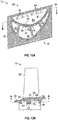
- FIGS. 12A and 12B yet another alternative embodiment of the present disclosure is illustrated.
- the pair of ribs 78 are eliminated and the channel 76 is located between rib or ledge 56.
- the second cover plate 80 is configured to have two vertical wall portions 83 and a horizontal wall portion 82 that extend from vertical portion 84 and contact internal wall or neck 44 so that the second cover plate 80 itself forms the extension of channel 76 below rib or ledge 56 allowing for the opening 42 to be located below the rib or ledge 56 as mentioned above.
- a plurality of flanges or tabs 90 are provided.
- the plurality of flanges or tabs 90 extend outwardly from the vertical wall portions 83 and horizontal wall portion 82 so that tabs or flanges 90 of the second cover plate 80 can be secured to internal wall or neck 44 and thus create the aforementioned channel extension that allows feed hole 42 to be located in a lower position on the internal wall or neck 44.
- the configuration of second cover plate 80 may be used separately from cover plate 58 or may comprise an integrally formed feature of a single cover plate.
- a single channel 76 with a single feed hole 42 may be provided or alternatively, a plurality of channels 76 (e.g., more than one) with corresponding feed holes 42 and cover plates 80 may also be provided.
- the channel 76 is formed in rib or ledge 56.
- the channel 76 is also formed in the surface of internal wall or neck 44 facing pocket 40.
- this channel 76 is configured to extend below rib or ledge 56 so that feed opening or hole 42 can be located in a position below platform rail 74 thus allowing for ease of formation of feed hole opening 42 as well as locating it in channel 76 further from areas of high stress.
- the second cover plate 80 is simply a planar member configured to cover the portion of channel 76 that is located below rib or ledge 56 and is formed in the surface of internal wall or neck 44.
- second cover plate 80 may be used separately from cover plate 58 or may comprise an integrally formed feature of a single cover plate. Still further and as discussed above, a single channel 76 with a single feed hole 42 may be provided or alternatively a plurality of channels 76 (e.g., more than one) with corresponding feed holes 42 and cover plates 80 may also be provided.
- the portion of cover plate 58 that is proximate to rail 74 is secured to rib or ledge 56 at a location away from a seal land 92 of the rail 74 such that the cover plate 58 does not interfere with a blade-to-blade seal 94, which in one non-limiting embodiment may comprise a feather seal, a damper, a pin seal or any other equivalent method for sealing one blade to another.
- a blade-to-blade seal 94 which in one non-limiting embodiment may comprise a feather seal, a damper, a pin seal or any other equivalent method for sealing one blade to another.
- the portion of cover plate 58 that is proximate to rail 74 is secured to rib or ledge 56 at a location above the seal land 92 of the rail 74 so that it does not interfere with the blade-to-blade seal 94.
- the feed hole 42 can be located at a different location than the cooling chamber 40, where there is more access to drill the hole and the stresses are lower.
- the chimney or channel 76 can provide more surface area to optimize the shape of the feed hole to lower stress.
Landscapes
- Engineering & Computer Science (AREA)
- Mechanical Engineering (AREA)
- General Engineering & Computer Science (AREA)
- Turbine Rotor Nozzle Sealing (AREA)
Claims (11)
- Schaufel für ein Gasturbinentriebwerk (10), wobei die Schaufel Folgendes umfasst:ein Schaufelprofil, das sich radial von einer Plattform (34) erstreckt, die an der Schaufel gesichert ist, wobei die Plattform (34) eine Außenfläche (48) aufweist, die über eine Vielzahl von Kühlöffnungen (46), die sich in der Plattform (34) befinden, mit einer inneren Kühltasche (40) der Plattform (34) in Fluidkommunikation steht, die sich von einer Mittellinie des Gasturbinentriebwerks aus bei einem niedrigeren Radius befindet als die Plattform (34);einen Kanal (76) in Fluidkommunikation mit der inneren Kühltasche (40);einen inneren Kühlholraum (26), der mit dem Kanal über eine Zuführöffnung (42) in Fluidkommunikation steht, die sich durch eine Innenwand der Schaufel erstreckt, wobei die Zuführöffnung (42) konfiguriert ist, um dem Kanal (76) Kühlluft aus dem inneren Kühlhohlraum (26) zuzuführen, undeine Abdeckplatte (58), welche die innere Kühltasche (40) und den Kanal (76) abdichtet,wobei sich ein Teil des Kanals (76) in einem Absatz (56) befindet, der sich in einem Innenumfang der inneren Kühltasche (40) befindet und wobei die Abdeckplatte (58) an dem Absatz (56) gesichert ist, wobei sich ein anderer Teil des Kanals (76) und die Zuführöffnung (42) von einer Mittellinie des Triebwerks aus bei einem niedrigeren Radius befinden als die innere Kühltasche (40).
- Schaufel nach Anspruch 1, ferner umfassend ein Paar von Rippen (78), die sich von dem Absatz (56) erstrecken und wobei sich der Teil des Kanals (76) auch zwischen dem Paar von Rippen (56) befindet und sich die Zuführöffnung (42) zwischen dem Paar von Rippen (78) befindet, wobei die Abdeckplatte (58) vorzugsweise einen ersten Abdeckplattenteil, der an dem Absatz gesichert ist und einen zweiten Abdeckplattenteil aufweist, der an dem Paar von Rippen (78) gesichert ist.
- Schaufel nach Anspruch 1 oder 2, wobei die Abdeckplatte (58) einen ersten Abdeckplattenteil, der an dem Absatz (56) gesichert ist und einen zweiten Abdeckplattenteil aufweist, der von der Mittellinie des Triebwerks aus bei einem niedrigeren Radius gesichert ist als der Absatz (56).
- Schaufel nach Anspruch 3, wobei der zweite Abdeckplattenteil mindestens eine "L"-förmige Konfiguration aufweist und/oder wobei der zweite Abdeckplattenteil einer getrennten Abdeckplatte entspricht, die mit dem ersten Abdeckplattenteil nicht einstückig ausgebildet ist.
- Schaufel nach einem der vorhergehenden Ansprüche, wobei die Zuführöffnung (42) eine längliche oder kreisförmige Konfiguration aufweist.
- Schaufel nach einem der Ansprüche 1 bis 5, wobei die Abdeckplatte (58) eine erste Abdeckplatte, die an dem Absatz (56) gesichert ist und eine zweite Abdeckplatte umfasst, die von der Mittellinie des Triebwerks aus bei einem niedrigeren Radius gesichert ist als der Absatz (56), wobei die zweite Abdeckplatte den Teil des Kanals (76) bildet, der sich von einer Mittellinie des Triebwerks aus bei einem niedrigeren Radius befindet als die innere Kühltasche (40),
und/oder wobei sich der Kanal (76) auch in der Innenwand befindet und wobei die Abdeckplatte (58) einen ersten Abdeckplattenteil, der an dem Absatz (56) gesichert ist und einen zweiten Abdeckplattenteil umfasst, der von der Mittellinie des Triebwerks aus bei einem niedrigeren Radius an der Innenwand gesichert ist als der Absatz (56). - Schaufel nach Anspruch 3 oder 4, wobei sich die Zuführöffnung (42) von der Mittellinie des Triebwerks aus bei einem niedrigeren Radius befindet als der Absatz (56) und von dem zweiten Abdeckplattenteil bedeckt wird, und wobei der Kanal (76) vorzugsweise von dem zweiten Abdeckplattenteil gebildet wird.
- Schaufel nach einem der vorhergehenden Ansprüche, wobei Kühlflüssigkeit in dem inneren Hohlraum (26) durch die Zuführöffnung (42) und den Kanal (76) hindurchgehen muss, bevor sie in die innere Kühltasche (40) gelangt.
- Schaufel (14) nach Anspruch 1, wobei sich der Kanal (76) vertikal von einer Mittellinie des Triebwerks zu einem niedrigeren Radius erstreckt als der Absatz (56) und wobei die Abdeckplatte (58) einen ersten Abdeckplattenteil, der an dem Absatz (56) gesichert ist, um die innere Kühltasche (40) abzudichten und einen zweiten Abdeckplattenteil umfasst, der von einer Mittellinie des Triebwerks aus bei einem niedrigeren Radius gesichert ist als der Absatz (56), um den Kanal (76) abzudichten, wobei sich die Zuführöffnung (42) vorzugsweise von einer Mittellinie des Triebwerks aus bei einem niedrigeren Radius befindet als der Absatz (56) und eine längliche oder kreisförmige Konfiguration aufweist, und wobei die Zuführöffnung (42) von dem zweiten Abdeckplattenteil bedeckt wird, und/oder wobei die erste Abdeckplatte von einem Rand einer Plattformschiene versenkt ist und wobei eine Dichtung von Schaufel zu Schaufel an dem Rand der Plattformschiene sitzt.
- Gasturbinentriebwerk, umfassend eine Schaufel nach einem der vorhergehenden Ansprüche.
- Verfahren zum Bereitstellen einer Kühlstrecke in einer Schaufel (14) eines Gasturbinentriebwerks (10), wobei das Verfahren Folgendes umfasst:fluidisches Koppeln einer Außenfläche einer Plattform (34) der Schaufel (14) an eine innere Kühltasche (40), die sich von einer Mittellinie des Triebwerks aus bei einem niedrigeren Radius befindet als die Plattform (34), über eine Vielzahl von Öffnungen (46) in der Plattform;fluidisches Koppeln der inneren Kühltasche (40) an eine Zuführöffnung (42), die sich in einer Innenwand der Schaufel (14) befindet, über einen Kanal (76), der sich durch einen Absatz (56) der inneren Kühltasche (40) erstreckt, wobei die Zuführöffnung (42) mit einem inneren Kühlhohlraum (26) des Schaufelprofils (28) in Fluidkommunikation steht, um dem Kanal (76) Kühlluft aus dem inneren Kühlhohlraum (26) zuzuführen; undSichern einer Abdeckplatte (58) an dem Absatz (56), wobei sich die Zuführöffnung (42) und ein Teil des Kanals (76) von der Mittellinie des Triebwerks aus bei einem niedrigeren Radius befinden als der Absatz (56).
Applications Claiming Priority (1)
| Application Number | Priority Date | Filing Date | Title |
|---|---|---|---|
| US14/993,765 US10082033B2 (en) | 2016-01-12 | 2016-01-12 | Gas turbine blade with platform cooling |
Publications (2)
| Publication Number | Publication Date |
|---|---|
| EP3192971A1 EP3192971A1 (de) | 2017-07-19 |
| EP3192971B1 true EP3192971B1 (de) | 2020-03-11 |
Family
ID=57794206
Family Applications (1)
| Application Number | Title | Priority Date | Filing Date |
|---|---|---|---|
| EP17151256.9A Active EP3192971B1 (de) | 2016-01-12 | 2017-01-12 | Gasturbinenschaufel mit plattformkühlung und verfahren |
Country Status (2)
| Country | Link |
|---|---|
| US (1) | US10082033B2 (de) |
| EP (1) | EP3192971B1 (de) |
Families Citing this family (4)
| Publication number | Priority date | Publication date | Assignee | Title |
|---|---|---|---|---|
| US10352182B2 (en) * | 2016-05-20 | 2019-07-16 | United Technologies Corporation | Internal cooling of stator vanes |
| EP3450685B1 (de) * | 2017-08-02 | 2020-04-29 | United Technologies Corporation | Gasturbinenmotorkomponente |
| US10822987B1 (en) | 2019-04-16 | 2020-11-03 | Pratt & Whitney Canada Corp. | Turbine stator outer shroud cooling fins |
| FR3127251A1 (fr) * | 2021-09-23 | 2023-03-24 | Safran | Refroidissement d’aubes de turbine de turbomachines |
Family Cites Families (7)
| Publication number | Priority date | Publication date | Assignee | Title |
|---|---|---|---|---|
| EP1028228A1 (de) | 1999-02-10 | 2000-08-16 | Siemens Aktiengesellschaft | Kühlvorrichtung für Turbinenlaufschaufelplattform |
| US7131817B2 (en) * | 2004-07-30 | 2006-11-07 | General Electric Company | Method and apparatus for cooling gas turbine engine rotor blades |
| US20060269409A1 (en) * | 2005-05-27 | 2006-11-30 | Mitsubishi Heavy Industries, Ltd. | Gas turbine moving blade having a platform, a method of forming the moving blade, a sealing plate, and a gas turbine having these elements |
| US8636470B2 (en) * | 2010-10-13 | 2014-01-28 | Honeywell International Inc. | Turbine blades and turbine rotor assemblies |
| US8641368B1 (en) * | 2011-01-25 | 2014-02-04 | Florida Turbine Technologies, Inc. | Industrial turbine blade with platform cooling |
| EP2660429A1 (de) * | 2012-05-03 | 2013-11-06 | Siemens Aktiengesellschaft | Abdichtanordnung für eine Düsenführungsschaufel und Gasturbine |
| EP2787170A1 (de) | 2013-04-04 | 2014-10-08 | Siemens Aktiengesellschaft | Technik zum Kühlen der Fuß-Seitenfläche einer Plattform eines Turbomaschinenteils |
-
2016
- 2016-01-12 US US14/993,765 patent/US10082033B2/en active Active
-
2017
- 2017-01-12 EP EP17151256.9A patent/EP3192971B1/de active Active
Non-Patent Citations (1)
| Title |
|---|
| None * |
Also Published As
| Publication number | Publication date |
|---|---|
| US20170198588A1 (en) | 2017-07-13 |
| EP3192971A1 (de) | 2017-07-19 |
| US10082033B2 (en) | 2018-09-25 |
Similar Documents
| Publication | Publication Date | Title |
|---|---|---|
| EP2834498B1 (de) | Kühlsystem für eine turbinenschaufel | |
| EP2562365B1 (de) | Außenschaufelluftdichtung mit mehrfacher Aufprallplattenanordnung | |
| EP2055898B1 (de) | Gasturbinentriebwerk mit in Umfangsrichtung angeordneten Schaufeln mit Plattformkühlung | |
| JP5898902B2 (ja) | タービン動翼のプラットフォーム区域を冷却するための装置及び方法 | |
| EP3121382B1 (de) | Gasturbinenmotoren mit kanalgekühlten haken zum halten eines teils relativ zu einer motorgehäusestruktur | |
| EP3088675B1 (de) | Laufschaufel und zugehörige gasturbine | |
| EP3192971B1 (de) | Gasturbinenschaufel mit plattformkühlung und verfahren | |
| EP3088674B1 (de) | Rotorblatt und zugehörige gasturbine | |
| US10053991B2 (en) | Gas turbine engine component having platform cooling channel | |
| EP2867493B1 (de) | Deckplatte für eine komponente eines gasturbinenmotors | |
| EP2530244B1 (de) | Ein Stator umliegend eines Rotors und Verfahren zur Kühlung | |
| EP3221561B1 (de) | Schaufelplattformkühlung und entsprechende gasturbine | |
| EP3246522B1 (de) | Interne kühlung von leitschaufeln | |
| EP3192972B1 (de) | Durchflussaustauschablenkplatteneinsatz für eine gasturbinenmotorkomponente | |
| EP3901418B1 (de) | Leitschaufel für ein gasturbinentriebwerk und verfahren zum übertragen eines kühlenden luftstroms innerhalb eines bauteils | |
| EP3203026B1 (de) | Gasturbinenschaufel mit sockelanordnung |
Legal Events
| Date | Code | Title | Description |
|---|---|---|---|
| PUAI | Public reference made under article 153(3) epc to a published international application that has entered the european phase |
Free format text: ORIGINAL CODE: 0009012 |
|
| STAA | Information on the status of an ep patent application or granted ep patent |
Free format text: STATUS: THE APPLICATION HAS BEEN PUBLISHED |
|
| AK | Designated contracting states |
Kind code of ref document: A1 Designated state(s): AL AT BE BG CH CY CZ DE DK EE ES FI FR GB GR HR HU IE IS IT LI LT LU LV MC MK MT NL NO PL PT RO RS SE SI SK SM TR |
|
| AX | Request for extension of the european patent |
Extension state: BA ME |
|
| STAA | Information on the status of an ep patent application or granted ep patent |
Free format text: STATUS: REQUEST FOR EXAMINATION WAS MADE |
|
| 17P | Request for examination filed |
Effective date: 20180118 |
|
| RBV | Designated contracting states (corrected) |
Designated state(s): AL AT BE BG CH CY CZ DE DK EE ES FI FR GB GR HR HU IE IS IT LI LT LU LV MC MK MT NL NO PL PT RO RS SE SI SK SM TR |
|
| RIC1 | Information provided on ipc code assigned before grant |
Ipc: F01D 5/18 20060101AFI20190205BHEP |
|
| GRAP | Despatch of communication of intention to grant a patent |
Free format text: ORIGINAL CODE: EPIDOSNIGR1 |
|
| STAA | Information on the status of an ep patent application or granted ep patent |
Free format text: STATUS: GRANT OF PATENT IS INTENDED |
|
| INTG | Intention to grant announced |
Effective date: 20190412 |
|
| GRAJ | Information related to disapproval of communication of intention to grant by the applicant or resumption of examination proceedings by the epo deleted |
Free format text: ORIGINAL CODE: EPIDOSDIGR1 |
|
| STAA | Information on the status of an ep patent application or granted ep patent |
Free format text: STATUS: REQUEST FOR EXAMINATION WAS MADE |
|
| GRAP | Despatch of communication of intention to grant a patent |
Free format text: ORIGINAL CODE: EPIDOSNIGR1 |
|
| STAA | Information on the status of an ep patent application or granted ep patent |
Free format text: STATUS: GRANT OF PATENT IS INTENDED |
|
| INTC | Intention to grant announced (deleted) | ||
| INTG | Intention to grant announced |
Effective date: 20190920 |
|
| GRAS | Grant fee paid |
Free format text: ORIGINAL CODE: EPIDOSNIGR3 |
|
| GRAA | (expected) grant |
Free format text: ORIGINAL CODE: 0009210 |
|
| STAA | Information on the status of an ep patent application or granted ep patent |
Free format text: STATUS: THE PATENT HAS BEEN GRANTED |
|
| AK | Designated contracting states |
Kind code of ref document: B1 Designated state(s): AL AT BE BG CH CY CZ DE DK EE ES FI FR GB GR HR HU IE IS IT LI LT LU LV MC MK MT NL NO PL PT RO RS SE SI SK SM TR |
|
| REG | Reference to a national code |
Ref country code: GB Ref legal event code: FG4D |
|
| REG | Reference to a national code |
Ref country code: CH Ref legal event code: EP |
|
| REG | Reference to a national code |
Ref country code: AT Ref legal event code: REF Ref document number: 1243373 Country of ref document: AT Kind code of ref document: T Effective date: 20200315 |
|
| REG | Reference to a national code |
Ref country code: DE Ref legal event code: R096 Ref document number: 602017012750 Country of ref document: DE |
|
| REG | Reference to a national code |
Ref country code: IE Ref legal event code: FG4D |
|
| PG25 | Lapsed in a contracting state [announced via postgrant information from national office to epo] |
Ref country code: RS Free format text: LAPSE BECAUSE OF FAILURE TO SUBMIT A TRANSLATION OF THE DESCRIPTION OR TO PAY THE FEE WITHIN THE PRESCRIBED TIME-LIMIT Effective date: 20200311 Ref country code: FI Free format text: LAPSE BECAUSE OF FAILURE TO SUBMIT A TRANSLATION OF THE DESCRIPTION OR TO PAY THE FEE WITHIN THE PRESCRIBED TIME-LIMIT Effective date: 20200311 Ref country code: NO Free format text: LAPSE BECAUSE OF FAILURE TO SUBMIT A TRANSLATION OF THE DESCRIPTION OR TO PAY THE FEE WITHIN THE PRESCRIBED TIME-LIMIT Effective date: 20200611 |
|
| REG | Reference to a national code |
Ref country code: NL Ref legal event code: MP Effective date: 20200311 |
|
| PG25 | Lapsed in a contracting state [announced via postgrant information from national office to epo] |
Ref country code: HR Free format text: LAPSE BECAUSE OF FAILURE TO SUBMIT A TRANSLATION OF THE DESCRIPTION OR TO PAY THE FEE WITHIN THE PRESCRIBED TIME-LIMIT Effective date: 20200311 Ref country code: GR Free format text: LAPSE BECAUSE OF FAILURE TO SUBMIT A TRANSLATION OF THE DESCRIPTION OR TO PAY THE FEE WITHIN THE PRESCRIBED TIME-LIMIT Effective date: 20200612 Ref country code: SE Free format text: LAPSE BECAUSE OF FAILURE TO SUBMIT A TRANSLATION OF THE DESCRIPTION OR TO PAY THE FEE WITHIN THE PRESCRIBED TIME-LIMIT Effective date: 20200311 Ref country code: LV Free format text: LAPSE BECAUSE OF FAILURE TO SUBMIT A TRANSLATION OF THE DESCRIPTION OR TO PAY THE FEE WITHIN THE PRESCRIBED TIME-LIMIT Effective date: 20200311 Ref country code: BG Free format text: LAPSE BECAUSE OF FAILURE TO SUBMIT A TRANSLATION OF THE DESCRIPTION OR TO PAY THE FEE WITHIN THE PRESCRIBED TIME-LIMIT Effective date: 20200611 |
|
| REG | Reference to a national code |
Ref country code: LT Ref legal event code: MG4D |
|
| PG25 | Lapsed in a contracting state [announced via postgrant information from national office to epo] |
Ref country code: NL Free format text: LAPSE BECAUSE OF FAILURE TO SUBMIT A TRANSLATION OF THE DESCRIPTION OR TO PAY THE FEE WITHIN THE PRESCRIBED TIME-LIMIT Effective date: 20200311 |
|
| PG25 | Lapsed in a contracting state [announced via postgrant information from national office to epo] |
Ref country code: CZ Free format text: LAPSE BECAUSE OF FAILURE TO SUBMIT A TRANSLATION OF THE DESCRIPTION OR TO PAY THE FEE WITHIN THE PRESCRIBED TIME-LIMIT Effective date: 20200311 Ref country code: RO Free format text: LAPSE BECAUSE OF FAILURE TO SUBMIT A TRANSLATION OF THE DESCRIPTION OR TO PAY THE FEE WITHIN THE PRESCRIBED TIME-LIMIT Effective date: 20200311 Ref country code: EE Free format text: LAPSE BECAUSE OF FAILURE TO SUBMIT A TRANSLATION OF THE DESCRIPTION OR TO PAY THE FEE WITHIN THE PRESCRIBED TIME-LIMIT Effective date: 20200311 Ref country code: SM Free format text: LAPSE BECAUSE OF FAILURE TO SUBMIT A TRANSLATION OF THE DESCRIPTION OR TO PAY THE FEE WITHIN THE PRESCRIBED TIME-LIMIT Effective date: 20200311 Ref country code: LT Free format text: LAPSE BECAUSE OF FAILURE TO SUBMIT A TRANSLATION OF THE DESCRIPTION OR TO PAY THE FEE WITHIN THE PRESCRIBED TIME-LIMIT Effective date: 20200311 Ref country code: IS Free format text: LAPSE BECAUSE OF FAILURE TO SUBMIT A TRANSLATION OF THE DESCRIPTION OR TO PAY THE FEE WITHIN THE PRESCRIBED TIME-LIMIT Effective date: 20200711 Ref country code: SK Free format text: LAPSE BECAUSE OF FAILURE TO SUBMIT A TRANSLATION OF THE DESCRIPTION OR TO PAY THE FEE WITHIN THE PRESCRIBED TIME-LIMIT Effective date: 20200311 Ref country code: PT Free format text: LAPSE BECAUSE OF FAILURE TO SUBMIT A TRANSLATION OF THE DESCRIPTION OR TO PAY THE FEE WITHIN THE PRESCRIBED TIME-LIMIT Effective date: 20200805 |
|
| REG | Reference to a national code |
Ref country code: AT Ref legal event code: MK05 Ref document number: 1243373 Country of ref document: AT Kind code of ref document: T Effective date: 20200311 |
|
| REG | Reference to a national code |
Ref country code: DE Ref legal event code: R097 Ref document number: 602017012750 Country of ref document: DE |
|
| PLBE | No opposition filed within time limit |
Free format text: ORIGINAL CODE: 0009261 |
|
| STAA | Information on the status of an ep patent application or granted ep patent |
Free format text: STATUS: NO OPPOSITION FILED WITHIN TIME LIMIT |
|
| PG25 | Lapsed in a contracting state [announced via postgrant information from national office to epo] |
Ref country code: ES Free format text: LAPSE BECAUSE OF FAILURE TO SUBMIT A TRANSLATION OF THE DESCRIPTION OR TO PAY THE FEE WITHIN THE PRESCRIBED TIME-LIMIT Effective date: 20200311 Ref country code: DK Free format text: LAPSE BECAUSE OF FAILURE TO SUBMIT A TRANSLATION OF THE DESCRIPTION OR TO PAY THE FEE WITHIN THE PRESCRIBED TIME-LIMIT Effective date: 20200311 Ref country code: IT Free format text: LAPSE BECAUSE OF FAILURE TO SUBMIT A TRANSLATION OF THE DESCRIPTION OR TO PAY THE FEE WITHIN THE PRESCRIBED TIME-LIMIT Effective date: 20200311 Ref country code: AT Free format text: LAPSE BECAUSE OF FAILURE TO SUBMIT A TRANSLATION OF THE DESCRIPTION OR TO PAY THE FEE WITHIN THE PRESCRIBED TIME-LIMIT Effective date: 20200311 |
|
| 26N | No opposition filed |
Effective date: 20201214 |
|
| PG25 | Lapsed in a contracting state [announced via postgrant information from national office to epo] |
Ref country code: SI Free format text: LAPSE BECAUSE OF FAILURE TO SUBMIT A TRANSLATION OF THE DESCRIPTION OR TO PAY THE FEE WITHIN THE PRESCRIBED TIME-LIMIT Effective date: 20200311 Ref country code: PL Free format text: LAPSE BECAUSE OF FAILURE TO SUBMIT A TRANSLATION OF THE DESCRIPTION OR TO PAY THE FEE WITHIN THE PRESCRIBED TIME-LIMIT Effective date: 20200311 |
|
| PG25 | Lapsed in a contracting state [announced via postgrant information from national office to epo] |
Ref country code: MC Free format text: LAPSE BECAUSE OF FAILURE TO SUBMIT A TRANSLATION OF THE DESCRIPTION OR TO PAY THE FEE WITHIN THE PRESCRIBED TIME-LIMIT Effective date: 20200311 |
|
| REG | Reference to a national code |
Ref country code: CH Ref legal event code: PL |
|
| PG25 | Lapsed in a contracting state [announced via postgrant information from national office to epo] |
Ref country code: LU Free format text: LAPSE BECAUSE OF NON-PAYMENT OF DUE FEES Effective date: 20210112 |
|
| REG | Reference to a national code |
Ref country code: BE Ref legal event code: MM Effective date: 20210131 |
|
| PG25 | Lapsed in a contracting state [announced via postgrant information from national office to epo] |
Ref country code: LI Free format text: LAPSE BECAUSE OF NON-PAYMENT OF DUE FEES Effective date: 20210131 Ref country code: CH Free format text: LAPSE BECAUSE OF NON-PAYMENT OF DUE FEES Effective date: 20210131 |
|
| PG25 | Lapsed in a contracting state [announced via postgrant information from national office to epo] |
Ref country code: IE Free format text: LAPSE BECAUSE OF NON-PAYMENT OF DUE FEES Effective date: 20210112 |
|
| PG25 | Lapsed in a contracting state [announced via postgrant information from national office to epo] |
Ref country code: BE Free format text: LAPSE BECAUSE OF NON-PAYMENT OF DUE FEES Effective date: 20210131 |
|
| REG | Reference to a national code |
Ref country code: DE Ref legal event code: R081 Ref document number: 602017012750 Country of ref document: DE Owner name: RAYTHEON TECHNOLOGIES CORPORATION (N.D.GES.D.S, US Free format text: FORMER OWNER: UNITED TECHNOLOGIES CORPORATION, FARMINGTON, CONN., US |
|
| PG25 | Lapsed in a contracting state [announced via postgrant information from national office to epo] |
Ref country code: HU Free format text: LAPSE BECAUSE OF FAILURE TO SUBMIT A TRANSLATION OF THE DESCRIPTION OR TO PAY THE FEE WITHIN THE PRESCRIBED TIME-LIMIT; INVALID AB INITIO Effective date: 20170112 |
|
| P01 | Opt-out of the competence of the unified patent court (upc) registered |
Effective date: 20230520 |
|
| PG25 | Lapsed in a contracting state [announced via postgrant information from national office to epo] |
Ref country code: CY Free format text: LAPSE BECAUSE OF FAILURE TO SUBMIT A TRANSLATION OF THE DESCRIPTION OR TO PAY THE FEE WITHIN THE PRESCRIBED TIME-LIMIT Effective date: 20200311 |
|
| PGFP | Annual fee paid to national office [announced via postgrant information from national office to epo] |
Ref country code: GB Payment date: 20231219 Year of fee payment: 8 |
|
| PGFP | Annual fee paid to national office [announced via postgrant information from national office to epo] |
Ref country code: FR Payment date: 20231219 Year of fee payment: 8 |
|
| PG25 | Lapsed in a contracting state [announced via postgrant information from national office to epo] |
Ref country code: MK Free format text: LAPSE BECAUSE OF FAILURE TO SUBMIT A TRANSLATION OF THE DESCRIPTION OR TO PAY THE FEE WITHIN THE PRESCRIBED TIME-LIMIT Effective date: 20200311 |
|
| PGFP | Annual fee paid to national office [announced via postgrant information from national office to epo] |
Ref country code: DE Payment date: 20231219 Year of fee payment: 8 |