EP3192707A1 - Steering lock device and assembling method of steering lock device - Google Patents
Steering lock device and assembling method of steering lock device Download PDFInfo
- Publication number
- EP3192707A1 EP3192707A1 EP16206980.1A EP16206980A EP3192707A1 EP 3192707 A1 EP3192707 A1 EP 3192707A1 EP 16206980 A EP16206980 A EP 16206980A EP 3192707 A1 EP3192707 A1 EP 3192707A1
- Authority
- EP
- European Patent Office
- Prior art keywords
- camshaft
- housing
- steering
- counterweight
- lock
- Prior art date
- Legal status (The legal status is an assumption and is not a legal conclusion. Google has not performed a legal analysis and makes no representation as to the accuracy of the status listed.)
- Granted
Links
- 238000000034 method Methods 0.000 title claims description 8
- 230000008878 coupling Effects 0.000 claims description 25
- 238000010168 coupling process Methods 0.000 claims description 25
- 238000005859 coupling reaction Methods 0.000 claims description 25
- 230000004308 accommodation Effects 0.000 claims description 13
- 238000010586 diagram Methods 0.000 description 3
- 229910000861 Mg alloy Inorganic materials 0.000 description 1
- 229910001297 Zn alloy Inorganic materials 0.000 description 1
- 238000003780 insertion Methods 0.000 description 1
- 230000037431 insertion Effects 0.000 description 1
- 238000004519 manufacturing process Methods 0.000 description 1
- 239000000463 material Substances 0.000 description 1
Images



Classifications
-
- B—PERFORMING OPERATIONS; TRANSPORTING
- B60—VEHICLES IN GENERAL
- B60R—VEHICLES, VEHICLE FITTINGS, OR VEHICLE PARTS, NOT OTHERWISE PROVIDED FOR
- B60R25/00—Fittings or systems for preventing or indicating unauthorised use or theft of vehicles
- B60R25/01—Fittings or systems for preventing or indicating unauthorised use or theft of vehicles operating on vehicle systems or fittings, e.g. on doors, seats or windscreens
- B60R25/02—Fittings or systems for preventing or indicating unauthorised use or theft of vehicles operating on vehicle systems or fittings, e.g. on doors, seats or windscreens operating on the steering mechanism
- B60R25/021—Fittings or systems for preventing or indicating unauthorised use or theft of vehicles operating on vehicle systems or fittings, e.g. on doors, seats or windscreens operating on the steering mechanism restraining movement of the steering column or steering wheel hub, e.g. restraining means controlled by ignition switch
- B60R25/02147—Fittings or systems for preventing or indicating unauthorised use or theft of vehicles operating on vehicle systems or fittings, e.g. on doors, seats or windscreens operating on the steering mechanism restraining movement of the steering column or steering wheel hub, e.g. restraining means controlled by ignition switch comprising a locking member having other than linear, axial or radial motion, e.g. rotatable; Steering column locking using balls, rollers or the like
-
- B—PERFORMING OPERATIONS; TRANSPORTING
- B60—VEHICLES IN GENERAL
- B60R—VEHICLES, VEHICLE FITTINGS, OR VEHICLE PARTS, NOT OTHERWISE PROVIDED FOR
- B60R25/00—Fittings or systems for preventing or indicating unauthorised use or theft of vehicles
- B60R25/01—Fittings or systems for preventing or indicating unauthorised use or theft of vehicles operating on vehicle systems or fittings, e.g. on doors, seats or windscreens
- B60R25/02—Fittings or systems for preventing or indicating unauthorised use or theft of vehicles operating on vehicle systems or fittings, e.g. on doors, seats or windscreens operating on the steering mechanism
- B60R25/021—Fittings or systems for preventing or indicating unauthorised use or theft of vehicles operating on vehicle systems or fittings, e.g. on doors, seats or windscreens operating on the steering mechanism restraining movement of the steering column or steering wheel hub, e.g. restraining means controlled by ignition switch
- B60R25/02105—Arrangement of the steering column thereof
-
- B—PERFORMING OPERATIONS; TRANSPORTING
- B60—VEHICLES IN GENERAL
- B60R—VEHICLES, VEHICLE FITTINGS, OR VEHICLE PARTS, NOT OTHERWISE PROVIDED FOR
- B60R25/00—Fittings or systems for preventing or indicating unauthorised use or theft of vehicles
- B60R25/01—Fittings or systems for preventing or indicating unauthorised use or theft of vehicles operating on vehicle systems or fittings, e.g. on doors, seats or windscreens
- B60R25/02—Fittings or systems for preventing or indicating unauthorised use or theft of vehicles operating on vehicle systems or fittings, e.g. on doors, seats or windscreens operating on the steering mechanism
- B60R25/021—Fittings or systems for preventing or indicating unauthorised use or theft of vehicles operating on vehicle systems or fittings, e.g. on doors, seats or windscreens operating on the steering mechanism restraining movement of the steering column or steering wheel hub, e.g. restraining means controlled by ignition switch
- B60R25/0211—Fittings or systems for preventing or indicating unauthorised use or theft of vehicles operating on vehicle systems or fittings, e.g. on doors, seats or windscreens operating on the steering mechanism restraining movement of the steering column or steering wheel hub, e.g. restraining means controlled by ignition switch comprising a locking member radially and linearly moved towards the steering column
- B60R25/02115—Fittings or systems for preventing or indicating unauthorised use or theft of vehicles operating on vehicle systems or fittings, e.g. on doors, seats or windscreens operating on the steering mechanism restraining movement of the steering column or steering wheel hub, e.g. restraining means controlled by ignition switch comprising a locking member radially and linearly moved towards the steering column key actuated
- B60R25/02126—Fittings or systems for preventing or indicating unauthorised use or theft of vehicles operating on vehicle systems or fittings, e.g. on doors, seats or windscreens operating on the steering mechanism restraining movement of the steering column or steering wheel hub, e.g. restraining means controlled by ignition switch comprising a locking member radially and linearly moved towards the steering column key actuated with linear bolt motion perpendicular to the lock axis
Definitions
- the present invention relates to a steering lock device and a method for assembling a steering lock device.
- Japanese Laid-Open Patent Publication No. 2007-055292 describes a prior art steering lock device that is mounted on a vehicle.
- the steering lock device includes a key cylinder and a camshaft, which is rotated when the key cylinder is rotated by a mechanical key, which is, for example, the blade of a key.
- the rotation of the camshaft moves a lock bar in a locking direction or an unlocking direction to lock or unlock the steering shaft.
- a method for manufacturing a steering lock device includes a step of coupling a camshaft to a key cylinder with the camshaft and the key cylinder positioned at predetermined angles relative to each other. For example, if the camshaft is rotated before the coupling of the camshaft and the key cylinder is completed, the rotation position of the camshaft needs to be set again relative to the key cylinder. Thus, assembling the steering lock device is burdensome.
- One aspect of the invention is a steering lock device for use with a steering shaft that includes a lock bar, a camshaft, and a counterweight.
- the lock bar is moved between an engagement position where the lock bar is engaged with the steering shaft and a non-engagement position where the lock bar is disengaged from the steering shaft.
- the camshaft is rotated in response to a locking operation and an unlocking operation.
- the camshaft includes a lock actuation cam that moves the lock bar to the engagement position in a locking direction, and rotation of the steering shaft is prohibited when the lock bar is engaged with the steering shaft.
- the counterweight is arranged on the camshaft to adjust rotational balance of the camshaft.
- the counterweight arranged on the camshaft balances rotation of the camshaft.
- the camshaft is stably located at an initial angular rotation position. This prevents or limits unintended rotation of the camshaft and facilitates the positioning of the camshaft and the key cylinder when coupling the camshaft.
- the steering lock device is easily assembled.
- the counterweight projects from the camshaft in a radial direction.
- This structure is advantageous for adjusting the mass of the counterweight at a high degree of freedom. For example, even when the camshaft includes another heavy portion, the heavy portion is easily balanced by the counterweight.
- the steering lock device further includes a housing and a key cylinder coupled to the housing.
- the housing is configured to allow a key interlock unit to be coupled to the housing.
- the key interlock unit permits removal of a key blade from the key cylinder only when a shift lever of a vehicle is located at a parking position.
- the camshaft includes an interlock cam having a cam surface that comes into contact with the key interlock unit and actuates the key interlock unit.
- the counterweight and the interlock cam are arranged to be symmetrical with respect to a shaft axis of the camshaft. In this structure, the counterweight is arranged proximate to the interlock cam. This facilitates the balancing of the camshaft.
- the housing includes an interlock coupling portion to which the key interlock unit is coupled, the interlock coupling portion includes an accommodation space that accommodates at least a portion of the key interlock unit, and the counterweight is arranged in the accommodation space.
- the accommodation space in the housing is utilized for the arrangement of the counterweight.
- Another aspect of the invention is a method for assembling a steering lock device that is for use with a steering shaft.
- the method includes coupling a lock bar to a housing of the steering lock device; coupling a camshaft, which includes a lock actuation cam, to the housing in the same direction as the lock bar; coupling a stopper to the housing in the same direction as the lock bar and the camshaft; coupling an urging element, which urges the stopper in a locking direction, to the stopper in the same direction as the lock bar, the camshaft, and the stopper; and coupling a cover, which closes an opening of the housing, to the housing in the same direction as the lock bar, the camshaft, the stopper, and the urging element.
- the steering lock device 1 is for use with, for example, a vehicle and configured to selectively prohibit and permit operation of a steering wheel (not shown).
- the steering lock device 1 includes a housing 2, which may also be referred to as a lock body, and a cover 4, which closes an opening 3 of the housing 2.
- the housing 2 is, for example, tubular and is formed from, for example, a magnesium alloy.
- the material of the cover 4 is, for example, a zinc alloy.
- the steering lock device 1 is coupled and fixed to a steering column 5, for example, by a bracket (not shown). In the example shown in the drawings, a steering shaft 5a is rotationally accommodated in the steering column 5.
- the housing 2 has one end in a longitudinal direction (X-axis direction in Fig. 1 ) of the steering lock device 1, and a key cylinder 7 is coupled to the longitudinal end and operated by a mechanical key, such as a key blade 50.
- the housing 2 has a distal end including a key cylinder port 2a.
- the key cylinder 7 is inserted into the key cylinder port 2a to close the key cylinder port 2a and couple the key cylinder 7 to the housing 2.
- the housing 2 has a basal end to which an ignition switch 8 is coupled.
- the ignition switch 8 switches power states (vehicle power states) in accordance with an operation position of the key cylinder 7.
- a key interlock unit 9 is coupled to one side of the housing 2.
- the key interlock unit 9 permits removal of the key blade 50 from the key cylinder 7 only when a shift lever 60 of a vehicle is located at a parking position.
- the steering lock device 1 includes a lock bar 13, which is capable of engaging the steering shaft 5a, a stopper 14, which is coupled to the lock bar 13, and a camshaft 15, which is rotated when the key cylinder 7 is operated with the key blade 50.
- the camshaft 15 is rotational about an axis L1 of the camshaft 15 in the clockwise direction and the counterclockwise direction.
- the housing 2 includes a component receptacle 16. The component receptacle 16 accommodates the lock bar 13, the stopper 14, and the camshaft 15.
- the component receptacle 16 includes shaft seats 17, which may be a plurality of (e.g., three) walls spaced apart from one another in a longitudinal direction of the housing 2. Each shaft seat 17 includes an arcuate slot 18.
- the camshaft 15 is rotationally mounted on the shaft seats 17 (slots 18).
- the camshaft 15 has one end that includes an elongated receptacle 19, to which the key cylinder 7 is coupled.
- the stopper 14 is coupled to the housing 2 in a manner that is linearly and reciprocally movable along two guides 21 (only one shown in Fig. 3 ), which are formed in inner wall surfaces of the housing 2.
- the stopper 14 may directly contact the lock bar 13 to adjust or vary the projecting length of the lock bar 13 from the housing 2 toward the steering shaft 5a (see Figs. 6A and 6B ).
- the stopper 14 may be referred to as a movable stopper.
- An urging element 22 is located between the cover 4 and the stopper 14 to urge the stopper 14 in the locking direction (lower direction in Fig. 3 ).
- the urging element 22 may be a coil spring, which may also be referred to as a lock spring.
- the urging element 22 has one end that is accommodated in a hole 23 located in an upper surface of the stopper 14.
- the urging element 22 has another end that is supported by an inner surface of the cover 4.
- the cover 4 is coupled to the housing 2 by press-fitting pins 24. The urging element 22 is compressed between the cover 4 and the stopper 14.
- the housing 2 includes an interlock coupling portion 25, to which the key interlock unit 9 is coupled.
- the interlock coupling portion 25 includes an accommodation space 26, which accommodates at least a portion of the key interlock unit 9.
- the accommodation space 26 is part of the component receptacle 16.
- the camshaft 15 includes a lock actuation cam 29 having a cam surface, which comes into contact with the stopper 14 to move the stopper 14 in the locking direction or the unlocking direction.
- the camshaft 15 includes a cylindrical portion 15a, from which the lock actuation cam 29 projects in a radial direction.
- the camshaft 15 includes an interlock cam 30 having a cam surface, which comes into contact with the key interlock unit 9 to actuate the key interlock unit 9.
- the lock actuation cam 29 and the interlock cam 30 are separated from each other in the axial direction.
- the lock actuation cam 29 and the interlock cam 30 are located at opposite sides of the camshaft 15 with respect to the shaft axis L1.
- the lock actuation cam 29 is located at a first axial position P1 of the camshaft 15.
- the interlock cam 30 is located at a second axial position P2 of the camshaft 15.
- the first axial position P1 and the second axial position P2 are different positions in the axial direction.
- the camshaft 15 includes a counterweight 31, which adjusts the rotational balance of the camshaft 15.
- the counterweight 31 projects from the camshaft 15 (cylindrical portion 15a) in a radial direction.
- the counterweight 31 is located at a side opposite to the side of the interlock cam 30.
- the counterweight 31 is arranged in the accommodation space 26, which is located in the interlock coupling portion 25 of the housing 2. The position and the shape of the counterweight 31 are changed in accordance with weights, shapes, and positions of the lock actuation cam 29 and the interlock cam 30 of the camshaft 15.
- the key interlock unit 9 and the interlock cam 30 are located next to each other in the interlock coupling portion 25 (accommodation space 26) in a width-wise direction (Y-axis direction in Fig. 4 ) of the steering lock device 1.
- the counterweight 31 and the interlock cam 30 are arranged to be symmetrical with respect to the shaft axis L1 of the camshaft 15.
- the lock bar 13 has a basal end including a recess 34.
- the stopper 14 includes an engagement portion 35 (refer to Fig. 3 ).
- the stopper 14 has a lower portion including a cutaway portion 36.
- the camshaft 15 is located in the cutaway portion 36 in a state in which the camshaft 15 is coupled to the housing 2.
- Fig. 6A for example, when the key cylinder 7 is moved to an ignition off position, the camshaft 15 is rotated in the locking direction (direction indicated by arrow R1 in Fig. 6A ) and the lock bar 13 and the stopper 14 are moved in a locking direction (direction indicated by arrow T1 in Fig. 6A ) by urging force of the urging element 22. Consequently, the lock bar 13 extends out of a hole 37 of the housing 2 and engages the steering shaft 5a. This locks the steering lock device 1.
- the camshaft 15 includes the counterweight 31. Since the counterweight 31 balances the rotation of the camshaft 15, the camshaft 15 is stably located at the initial angular rotation position when coupling the camshaft 15. This prevents or limits unintended rotation of the camshaft 15 when coupling the camshaft 15. Thus, the camshaft 15 and the key cylinder 7 are easily positioned.
- the counterweight 31 projects from the camshaft 15 in a radial direction.
- the counterweight 31, which is a projection, is advantageous for adjusting the mass of the counterweight 31 at a high degree of freedom. For example, even when the interlock cam 30 is relatively heavy or large, the counterweight 31 easily balances the interlock cam 30.
- the counterweight 31 and the interlock cam 30 are arranged to be symmetrical with respect to the shaft axis L1 of the camshaft 15.
- the interlock cam 30 projects from the second axial position P2 of the camshaft 15 in the radial direction of the camshaft 15, which is rightward in Fig. 2 .
- the counterweight 31 radially projects from the second axial position P2 of the camshaft 15 in a direction opposite to the direction of the interlock cam 30, which is leftward in Fig. 2 .
- the counterweight 31 is arranged proximate to the interlock cam 30. This is advantageous for facilitating the balancing of the rotation of the camshaft 15.
- the housing 2 includes the accommodation space 26, which accommodates at least a portion of the key interlock unit 9.
- the camshaft 15 includes the counterweight 31
- the counterweight 31 is arranged in the accommodation space 26. This utilizes the empty space of the accommodation space 26 when arranging the counterweight 31. Thus, the empty space in the housing 2 is efficiently used when adding the counterweight 31.
- Figs. 7A to 7E show cross-sections of the housing 2 including the opening 3.
- the lock bar 13, the stopper 14, and the camshaft 15 are inserted into the housing 2 through the opening 3, which differs from the key cylinder port 2a.
- the lock bar 13 is coupled to the housing 2 of the steering lock device 1 (first step).
- the lock bar 13 is coupled to the housing 2 in a downward direction (direction of arrow Z1 in Fig. 7A ). It is desirable that the lock bar 13 be supported, for example, by a hand so that the lock bar 13 will not fall from the hole 37 of the housing 2.
- the camshaft 15 is coupled to the housing 2 in the same direction as the lock bar 13 (second step).
- the camshaft 15 is coupled to the housing 2 in a downward direction (direction of arrow Z1 in Fig. 7B ).
- the camshaft 15 is, for example, mounted on the shaft seats 17 in the housing 2 when coupled.
- the camshaft 15 since the camshaft 15 includes the counterweight 31, the camshaft 15 is balanced in the direction extending along the shaft axis L1.
- unintentional rotation of the camshaft 15 in the direction extending along the shaft axis L1 is restricted. This ensures easiness of the coupling.
- the stopper 14 is coupled to the housing 2 in the same direction as the lock bar 13 and the camshaft 15 (third step). At this time, the stopper 14 engages the lock bar 13 when coupled. For example, the stopper 14 is also coupled to the housing 2 in a downward direction (direction of arrow Z1 in Fig. 7C ).
- the urging element 22 which urges the stopper 14 (the lock bar 13) in the locking direction, is coupled to the stopper 14 in the same direction as the lock bar 13, the camshaft 15, and the stopper 14 (fourth step).
- the urging element 22 is inserted into the hole 23 of the stopper 14 in a downward direction (direction of arrow Z1 in Fig. 7D ) and coupled to the housing 2.
- the cover 4 is coupled to the housing 2 in the same direction as the lock bar 13, the camshaft 15, the stopper 14, and the urging element 22 to close the opening 3 of the housing 2 with the cover 4 (fifth step).
- the cover 4 is aligned with the housing 2 in a downward direction (direction of arrow Z1 in Fig. 7E ), and the cover 4 is coupled to the housing 2 by the press-fitting pins 24. The above steps complete the assembling of the steering lock device.
- the lock bar 13, the camshaft 15, the stopper 14, the urging element 22, and the cover 4 are sequentially coupled to the housing 2 in the same direction (refer to arrows Z1 in Figs. 7A to 7E ).
- the counterweight 31 of the camshaft 15 prevents the camshaft 15, which is coupled to the housing 2, from rotating about the shaft axis L1.
- the steering lock device 1 is easily assembled.
- the embodiment may be modified as follows.
- the camshaft 15 include a single counterweight 31.
- the camshaft 15 may include a plurality of counterweights.
- a camshaft may include a subset of divided counterweight pieces at the position of the counterweight 31 of the embodiment.
- the shape of the counterweight 31 may be changed.
- the counterweight 31 may be located at a position that differs from the side opposite to the interlock cam 30.
- the counterweight 31 may be located at a position that differs from the accommodation space 26.
- the counterweight 31 and the camshaft 15 be a single piece member.
- the counterweight 31 and the camshaft 15 may be discrete members. In this case, the counterweight 31 and the camshaft 15 are manufactured separately, and thereafter the counterweight 31 is fixed to the camshaft 15.
- the mass of the counterweight 31 is determined to stabilize the camshaft 15 at the initial angular rotation position.
- the camshaft 15 may be configured to directly move the lock bar 13.
- the stopper 14 and the lock bar 13 may be integrally formed as a one-piece member.
- the opening 3 of the housing 2 only needs to be large enough to allow for insertion of the camshaft 15.
- the opening 3 be located in the upper surface of the housing 2. However, the opening 3 may be located at a position other than the upper surface such as a side surface of the housing 2.
- each component of the steering lock device 1 be coupled in the downward direction shown in Fig. 3 .
- the direction may be changed as long as the elements are coupled in the same direction.
- the interlock cam 30 may be omitted.
- the steering lock device 1 may be of a mechanical-driven type or an electrical-driven type.
Landscapes
- Engineering & Computer Science (AREA)
- Mechanical Engineering (AREA)
- Lock And Its Accessories (AREA)
Abstract
Description
- The present invention relates to a steering lock device and a method for assembling a steering lock device.
- Japanese Laid-Open Patent Publication No.
2007-055292 - A method for manufacturing a steering lock device includes a step of coupling a camshaft to a key cylinder with the camshaft and the key cylinder positioned at predetermined angles relative to each other. For example, if the camshaft is rotated before the coupling of the camshaft and the key cylinder is completed, the rotation position of the camshaft needs to be set again relative to the key cylinder. Thus, assembling the steering lock device is burdensome.
- It is an object of the present invention to provide a steering lock device that is easy to assemble and a method for assembling the steering lock device.
- One aspect of the invention is a steering lock device for use with a steering shaft that includes a lock bar, a camshaft, and a counterweight. The lock bar is moved between an engagement position where the lock bar is engaged with the steering shaft and a non-engagement position where the lock bar is disengaged from the steering shaft. The camshaft is rotated in response to a locking operation and an unlocking operation. The camshaft includes a lock actuation cam that moves the lock bar to the engagement position in a locking direction, and rotation of the steering shaft is prohibited when the lock bar is engaged with the steering shaft. The counterweight is arranged on the camshaft to adjust rotational balance of the camshaft.
- In this structure, the counterweight arranged on the camshaft balances rotation of the camshaft. Thus, when coupling the camshaft, the camshaft is stably located at an initial angular rotation position. This prevents or limits unintended rotation of the camshaft and facilitates the positioning of the camshaft and the key cylinder when coupling the camshaft. Thus, the steering lock device is easily assembled.
- In one example of the steering lock device, the counterweight projects from the camshaft in a radial direction.
- This structure is advantageous for adjusting the mass of the counterweight at a high degree of freedom. For example, even when the camshaft includes another heavy portion, the heavy portion is easily balanced by the counterweight.
- One example of the steering lock device further includes a housing and a key cylinder coupled to the housing. The housing is configured to allow a key interlock unit to be coupled to the housing. The key interlock unit permits removal of a key blade from the key cylinder only when a shift lever of a vehicle is located at a parking position. The camshaft includes an interlock cam having a cam surface that comes into contact with the key interlock unit and actuates the key interlock unit. The counterweight and the interlock cam are arranged to be symmetrical with respect to a shaft axis of the camshaft. In this structure, the counterweight is arranged proximate to the interlock cam. This facilitates the balancing of the camshaft.
- In one example of the steering lock device, the housing includes an interlock coupling portion to which the key interlock unit is coupled, the interlock coupling portion includes an accommodation space that accommodates at least a portion of the key interlock unit, and the counterweight is arranged in the accommodation space. In this structure, the accommodation space in the housing is utilized for the arrangement of the counterweight. Thus, the empty space in the housing is efficiently used when adding the counterweight.
- Another aspect of the invention is a method for assembling a steering lock device that is for use with a steering shaft. The method includes coupling a lock bar to a housing of the steering lock device; coupling a camshaft, which includes a lock actuation cam, to the housing in the same direction as the lock bar; coupling a stopper to the housing in the same direction as the lock bar and the camshaft; coupling an urging element, which urges the stopper in a locking direction, to the stopper in the same direction as the lock bar, the camshaft, and the stopper; and coupling a cover, which closes an opening of the housing, to the housing in the same direction as the lock bar, the camshaft, the stopper, and the urging element.
- This configuration allows each component of the steering lock device to be coupled to the housing in the same direction. Thus, the steering lock device is easily assembled.
- Other aspects and advantages of the embodiments will become apparent from the following description, taken in conjunction with the accompanying drawings, illustrating by way of example the principles of the invention.
- The embodiments, together with objects and advantages thereof, may best be understood by reference to the following description of the presently preferred embodiments together with the accompanying drawings in which:
-
Fig. 1 is a perspective view showing one embodiment of a steering lock device; -
Fig. 2A is a plan view of a camshaft; -
Fig. 2B is a diagram showing a cam surface of a lock actuation cam arranged on the camshaft; -
Fig. 3 is an exploded perspective view of the steering lock device; -
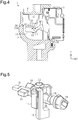
Fig. 4 is a cross-sectional view of the steering lock device including a counterweight; -
Fig. 5 is a perspective view of a lock bar, the camshaft, and a stopper; -
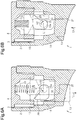
Fig. 6A is a diagram showing a locked state; -
Fig. 6B is a diagram showing an unlocked state; and -
Figs. 7A to 7E are schematic cross-sectional views showing the assembling of the steering lock device. - One embodiment of a
steering lock device 1 will now be described. - As shown in
Fig. 1 , thesteering lock device 1 is for use with, for example, a vehicle and configured to selectively prohibit and permit operation of a steering wheel (not shown). Thesteering lock device 1 includes ahousing 2, which may also be referred to as a lock body, and acover 4, which closes anopening 3 of thehousing 2. Thehousing 2 is, for example, tubular and is formed from, for example, a magnesium alloy. The material of thecover 4 is, for example, a zinc alloy. Thesteering lock device 1 is coupled and fixed to a steering column 5, for example, by a bracket (not shown). In the example shown in the drawings, a steering shaft 5a is rotationally accommodated in the steering column 5. - The
housing 2 has one end in a longitudinal direction (X-axis direction inFig. 1 ) of thesteering lock device 1, and a key cylinder 7 is coupled to the longitudinal end and operated by a mechanical key, such as akey blade 50. Thehousing 2 has a distal end including akey cylinder port 2a. The key cylinder 7 is inserted into thekey cylinder port 2a to close thekey cylinder port 2a and couple the key cylinder 7 to thehousing 2. Thehousing 2 has a basal end to which anignition switch 8 is coupled. Theignition switch 8 switches power states (vehicle power states) in accordance with an operation position of the key cylinder 7. Akey interlock unit 9 is coupled to one side of thehousing 2. Thekey interlock unit 9 permits removal of thekey blade 50 from the key cylinder 7 only when ashift lever 60 of a vehicle is located at a parking position. - As shown in
Fig. 3 , thesteering lock device 1 includes alock bar 13, which is capable of engaging the steering shaft 5a, astopper 14, which is coupled to thelock bar 13, and acamshaft 15, which is rotated when the key cylinder 7 is operated with thekey blade 50. As indicated by two-direction arrows R inFig. 3 , thecamshaft 15 is rotational about an axis L1 of thecamshaft 15 in the clockwise direction and the counterclockwise direction. Thehousing 2 includes acomponent receptacle 16. Thecomponent receptacle 16 accommodates thelock bar 13, thestopper 14, and thecamshaft 15. Thecomponent receptacle 16 includes shaft seats 17, which may be a plurality of (e.g., three) walls spaced apart from one another in a longitudinal direction of thehousing 2. Eachshaft seat 17 includes anarcuate slot 18. Thecamshaft 15 is rotationally mounted on the shaft seats 17 (slots 18). Thecamshaft 15 has one end that includes anelongated receptacle 19, to which the key cylinder 7 is coupled. - The
stopper 14 is coupled to thehousing 2 in a manner that is linearly and reciprocally movable along two guides 21 (only one shown inFig. 3 ), which are formed in inner wall surfaces of thehousing 2. Thestopper 14 may directly contact thelock bar 13 to adjust or vary the projecting length of thelock bar 13 from thehousing 2 toward the steering shaft 5a (seeFigs. 6A and 6B ). Thestopper 14 may be referred to as a movable stopper. An urgingelement 22 is located between thecover 4 and thestopper 14 to urge thestopper 14 in the locking direction (lower direction inFig. 3 ). The urgingelement 22 may be a coil spring, which may also be referred to as a lock spring. The urgingelement 22 has one end that is accommodated in ahole 23 located in an upper surface of thestopper 14. The urgingelement 22 has another end that is supported by an inner surface of thecover 4. Thecover 4 is coupled to thehousing 2 by press-fitting pins 24. The urgingelement 22 is compressed between thecover 4 and thestopper 14. - The
housing 2 includes aninterlock coupling portion 25, to which thekey interlock unit 9 is coupled. Theinterlock coupling portion 25 includes anaccommodation space 26, which accommodates at least a portion of thekey interlock unit 9. Theaccommodation space 26 is part of thecomponent receptacle 16. - As shown in
Figs. 2A, 2B , and3 , thecamshaft 15 includes alock actuation cam 29 having a cam surface, which comes into contact with thestopper 14 to move thestopper 14 in the locking direction or the unlocking direction. Thecamshaft 15 includes acylindrical portion 15a, from which thelock actuation cam 29 projects in a radial direction. When thestopper 14 and thecamshaft 15 are coupled to thehousing 2, thelock actuation cam 29 is in contact with thestopper 14. - The
camshaft 15 includes aninterlock cam 30 having a cam surface, which comes into contact with thekey interlock unit 9 to actuate thekey interlock unit 9. Thelock actuation cam 29 and theinterlock cam 30 are separated from each other in the axial direction. Thelock actuation cam 29 and theinterlock cam 30 are located at opposite sides of thecamshaft 15 with respect to the shaft axis L1. In the example shown in the drawings, thelock actuation cam 29 is located at a first axial position P1 of thecamshaft 15. Theinterlock cam 30 is located at a second axial position P2 of thecamshaft 15. The first axial position P1 and the second axial position P2 are different positions in the axial direction. - The
camshaft 15 includes acounterweight 31, which adjusts the rotational balance of thecamshaft 15. Thecounterweight 31 projects from the camshaft 15 (cylindrical portion 15a) in a radial direction. Thecounterweight 31 is located at a side opposite to the side of theinterlock cam 30. Thecounterweight 31 is arranged in theaccommodation space 26, which is located in theinterlock coupling portion 25 of thehousing 2. The position and the shape of thecounterweight 31 are changed in accordance with weights, shapes, and positions of thelock actuation cam 29 and theinterlock cam 30 of thecamshaft 15. - As shown in
Fig. 4 , thekey interlock unit 9 and theinterlock cam 30 are located next to each other in the interlock coupling portion 25 (accommodation space 26) in a width-wise direction (Y-axis direction inFig. 4 ) of thesteering lock device 1. As shown inFig. 2 , thecounterweight 31 and theinterlock cam 30 are arranged to be symmetrical with respect to the shaft axis L1 of thecamshaft 15. - As shown in
Fig. 5 , thelock bar 13 has a basal end including arecess 34. Thestopper 14 includes an engagement portion 35 (refer toFig. 3 ). When therecess 34 engages theengagement portion 35, thelock bar 13 is coupled to thestopper 14. Thus, thelock bar 13 and thestopper 14 are moved integrally with each other in the locking direction and the unlocking direction. Thestopper 14 has a lower portion including acutaway portion 36. Thecamshaft 15 is located in thecutaway portion 36 in a state in which thecamshaft 15 is coupled to thehousing 2. - As shown in
Fig. 6A , for example, when the key cylinder 7 is moved to an ignition off position, thecamshaft 15 is rotated in the locking direction (direction indicated by arrow R1 inFig. 6A ) and thelock bar 13 and thestopper 14 are moved in a locking direction (direction indicated by arrow T1 inFig. 6A ) by urging force of the urgingelement 22. Consequently, thelock bar 13 extends out of ahole 37 of thehousing 2 and engages the steering shaft 5a. This locks thesteering lock device 1. - As shown in
Fig. 6B , for example, when the key cylinder 7 is moved to an ACC on position or an ignition on position, thecamshaft 15 is rotated in the unlocking direction (direction indicated by arrow R2 inFig. 6B ) and thelock bar 13 and thestopper 14 are lifted by thelock actuation cam 29 of thecamshaft 15 in an unlocking direction (direction indicated by arrow T2 inFig. 6B ) against the urging force of the urgingelement 22. Consequently, thelock bar 13 is separated from the steering shaft 5a and retracted into thehousing 2. This unlocks thesteering lock device 1. - The operation of the
steering lock device 1 will now be described. - As shown in
Fig. 4 , in thesteering lock device 1 that selectively prohibits and permits operation of the steering wheel by moving thelock bar 13 in the locking direction with use of the camshaft 15 (the lock actuation cam 29), thecamshaft 15 includes thecounterweight 31. Since thecounterweight 31 balances the rotation of thecamshaft 15, thecamshaft 15 is stably located at the initial angular rotation position when coupling thecamshaft 15. This prevents or limits unintended rotation of thecamshaft 15 when coupling thecamshaft 15. Thus, thecamshaft 15 and the key cylinder 7 are easily positioned. - The
counterweight 31 projects from thecamshaft 15 in a radial direction. Thecounterweight 31, which is a projection, is advantageous for adjusting the mass of thecounterweight 31 at a high degree of freedom. For example, even when theinterlock cam 30 is relatively heavy or large, thecounterweight 31 easily balances theinterlock cam 30. - The
counterweight 31 and theinterlock cam 30 are arranged to be symmetrical with respect to the shaft axis L1 of thecamshaft 15. For example, theinterlock cam 30 projects from the second axial position P2 of thecamshaft 15 in the radial direction of thecamshaft 15, which is rightward inFig. 2 . Thecounterweight 31 radially projects from the second axial position P2 of thecamshaft 15 in a direction opposite to the direction of theinterlock cam 30, which is leftward inFig. 2 . Thecounterweight 31 is arranged proximate to theinterlock cam 30. This is advantageous for facilitating the balancing of the rotation of thecamshaft 15. - The
housing 2 includes theaccommodation space 26, which accommodates at least a portion of thekey interlock unit 9. When thecamshaft 15 includes thecounterweight 31, thecounterweight 31 is arranged in theaccommodation space 26. This utilizes the empty space of theaccommodation space 26 when arranging thecounterweight 31. Thus, the empty space in thehousing 2 is efficiently used when adding thecounterweight 31. - Assembling of the
steering lock device 1 will now be described with reference toFigs. 7A to 7E. Figs. 7A to 7E show cross-sections of thehousing 2 including theopening 3. Thelock bar 13, thestopper 14, and thecamshaft 15 are inserted into thehousing 2 through theopening 3, which differs from thekey cylinder port 2a. - As shown in
Fig. 7A , for example, thelock bar 13 is coupled to thehousing 2 of the steering lock device 1 (first step). For example, thelock bar 13 is coupled to thehousing 2 in a downward direction (direction of arrow Z1 inFig. 7A ). It is desirable that thelock bar 13 be supported, for example, by a hand so that thelock bar 13 will not fall from thehole 37 of thehousing 2. - As shown in
Fig. 7B , after thelock bar 13 is coupled, thecamshaft 15 is coupled to thehousing 2 in the same direction as the lock bar 13 (second step). For example, when the rotation position of thecamshaft 15 about the shaft axis L1 conforms to the ignition off position of the key cylinder 7, thecamshaft 15 is coupled to thehousing 2 in a downward direction (direction of arrow Z1 inFig. 7B ). Thecamshaft 15 is, for example, mounted on the shaft seats 17 in thehousing 2 when coupled. For example, since thecamshaft 15 includes thecounterweight 31, thecamshaft 15 is balanced in the direction extending along the shaft axis L1. Thus, when thecamshaft 15 is coupled to thehousing 2, unintentional rotation of thecamshaft 15 in the direction extending along the shaft axis L1 is restricted. This ensures easiness of the coupling. - As shown in
Fig. 7C , after thecamshaft 15 is coupled, thestopper 14 is coupled to thehousing 2 in the same direction as thelock bar 13 and the camshaft 15 (third step). At this time, thestopper 14 engages thelock bar 13 when coupled. For example, thestopper 14 is also coupled to thehousing 2 in a downward direction (direction of arrow Z1 inFig. 7C ). - As shown in
Fig. 7D , after thestopper 14 is coupled, the urgingelement 22, which urges the stopper 14 (the lock bar 13) in the locking direction, is coupled to thestopper 14 in the same direction as thelock bar 13, thecamshaft 15, and the stopper 14 (fourth step). For example, the urgingelement 22 is inserted into thehole 23 of thestopper 14 in a downward direction (direction of arrow Z1 inFig. 7D ) and coupled to thehousing 2. - As shown in
Fig. 7E , after the urgingelement 22 is coupled, thecover 4 is coupled to thehousing 2 in the same direction as thelock bar 13, thecamshaft 15, thestopper 14, and the urgingelement 22 to close theopening 3 of thehousing 2 with the cover 4 (fifth step). For example, thecover 4 is aligned with thehousing 2 in a downward direction (direction of arrow Z1 inFig. 7E ), and thecover 4 is coupled to thehousing 2 by the press-fitting pins 24. The above steps complete the assembling of the steering lock device. - The
lock bar 13, thecamshaft 15, thestopper 14, the urgingelement 22, and thecover 4 are sequentially coupled to thehousing 2 in the same direction (refer to arrows Z1 inFigs. 7A to 7E ). This facilitates the assembling of thesteering lock device 1. Thecounterweight 31 of thecamshaft 15 prevents thecamshaft 15, which is coupled to thehousing 2, from rotating about the shaft axis L1. Thus, thesteering lock device 1 is easily assembled. - The embodiment may be modified as follows.
- It is preferred that the
camshaft 15 include asingle counterweight 31. However, thecamshaft 15 may include a plurality of counterweights. In one example, a camshaft may include a subset of divided counterweight pieces at the position of thecounterweight 31 of the embodiment. - The shape of the
counterweight 31 may be changed. - The
counterweight 31 may be located at a position that differs from the side opposite to theinterlock cam 30. - The
counterweight 31 may be located at a position that differs from theaccommodation space 26. - It is preferred that the
counterweight 31 and thecamshaft 15 be a single piece member. However, thecounterweight 31 and thecamshaft 15 may be discrete members. In this case, thecounterweight 31 and thecamshaft 15 are manufactured separately, and thereafter thecounterweight 31 is fixed to thecamshaft 15. - The mass of the
counterweight 31 is determined to stabilize thecamshaft 15 at the initial angular rotation position. - When the
stopper 14 is omitted, thecamshaft 15 may be configured to directly move thelock bar 13. - The
stopper 14 and thelock bar 13 may be integrally formed as a one-piece member. - The
opening 3 of thehousing 2 only needs to be large enough to allow for insertion of thecamshaft 15. - It is preferred that the
opening 3 be located in the upper surface of thehousing 2. However, theopening 3 may be located at a position other than the upper surface such as a side surface of thehousing 2. - It is preferred that each component of the
steering lock device 1 be coupled in the downward direction shown inFig. 3 . However, the direction may be changed as long as the elements are coupled in the same direction. - The
interlock cam 30 may be omitted. - The
steering lock device 1 may be of a mechanical-driven type or an electrical-driven type. - It should be apparent to those skilled in the art that the present invention may be embodied in many other specific forms without departing from the scope of the invention. For example, one or more of the components may be omitted from the components described in the embodiments (or one or more aspects thereof). Further, components in different embodiments may be appropriately combined.
- The present examples and embodiments are to be considered as illustrative and not restrictive, and the invention is not to be limited to the details given herein, but may be modified within the scope and equivalence of the appended claims.
Claims (8)
- A steering lock device (1) for use with a steering shaft (5a), the steering lock device (1) comprising:a lock bar (13) moved between an engagement position where the lock bar (13) is engaged with the steering shaft (5a) and a non-engagement position where the lock bar (13) is disengaged from the steering shaft (5a);a camshaft (15) that is rotated in response to a locking operation and an unlocking operation, wherein the camshaft (15) includes a lock actuation cam (29) that moves the lock bar (13) to the engagement position in a locking direction (T2), and rotation of the steering shaft (5a) is prohibited when the lock bar (13) is engaged with the steering shaft (5a); anda counterweight (31) arranged on the camshaft (15), wherein the counterweight (31) adjusts rotational balance of the camshaft (15).
- The steering lock device (1) according to claim 1, wherein the counterweight (31) projects from the camshaft (15) in a radial direction.
- The steering lock device (1) according to claim 1 or 2, further comprising:a housing (2); anda key cylinder (7) coupled to the housing (2), whereinthe housing (2) is configured to allow a key interlock unit (9) to be coupled to the housing (2),the key interlock unit (9) permits removal of a key blade (50) from the key cylinder (7) only when a shift lever (60) of a vehicle is located at a parking position,the camshaft (15) includes an interlock cam (30) having a cam surface that comes into contact with the key interlock unit (9) and actuates the key interlock unit (9), andthe counterweight (31) and the interlock cam (30) are arranged to be symmetrical with respect to a shaft axis (L1) of the camshaft (15).
- The steering lock device (1) according to claim 3, wherein
the housing (2) includes an interlock coupling portion (25) to which the key interlock unit (9) is coupled,
the interlock coupling portion (25) includes an accommodation space (26) that accommodates at least a portion of the key interlock unit (9), and
the counterweight (31) is arranged in the accommodation space (26). - The steering lock device (1) according to claim 1, wherein
the lock actuation cam (29) is located at a first axial position (P1) of the camshaft (15), and
the counterweight (31) is located at a second axial position (P2) of the camshaft (15) that differs from the first axial position (P1). - The steering lock device (1) according to claim 5, wherein
the lock actuation cam (29) projects from the first axial position (P1) of the camshaft (15) in a radial direction, and
the counterweight (31) projects from the second axial position (P2) of the camshaft (15) in the same radial direction as the lock actuation cam (29). - The steering lock device (1) according to claim 5 or 6, further comprising:a housing (2) configured to be fixed to a steering column (5) that accommodates the steering shaft (5a); anda key cylinder (7) coupled to the camshaft (15) in the housing (2),wherein the counterweight (31) is configured to stabilize the camshaft (15) at an initial angular rotation position in the housing (2) before the camshaft (15) is coupled to the key cylinder (7).
- A method for assembling a steering lock device (1) that is for use with a steering shaft (5a), the method comprising:coupling a lock bar (13) to a housing (2) of the steering lock device (1);coupling a camshaft (15) to the housing (2) in the same direction as the lock bar (13), wherein the camshaft (15) includes a lock actuation cam (29);coupling a stopper (14) to the housing (2) in the same direction as the lock bar (13) and the camshaft (15);coupling an urging element (22) to the stopper (14) in the same direction as the lock bar (13), the camshaft (15), and the stopper (14), wherein the urging element (22) urges the stopper (14) in a locking direction; andcoupling a cover (4) to the housing (2) in the same direction as the lock bar (13), the camshaft (15), the stopper (14), and the urging element (22), wherein the cover (4) closes an opening (3) of the housing (2).
Applications Claiming Priority (1)
| Application Number | Priority Date | Filing Date | Title |
|---|---|---|---|
| JP2016005120A JP6471105B2 (en) | 2016-01-14 | 2016-01-14 | Steering lock device and method of assembling steering locking device |
Publications (2)
| Publication Number | Publication Date |
|---|---|
| EP3192707A1 true EP3192707A1 (en) | 2017-07-19 |
| EP3192707B1 EP3192707B1 (en) | 2020-03-11 |
Family
ID=57614246
Family Applications (1)
| Application Number | Title | Priority Date | Filing Date |
|---|---|---|---|
| EP16206980.1A Active EP3192707B1 (en) | 2016-01-14 | 2016-12-27 | Steering lock device and assembling method of steering lock device |
Country Status (4)
| Country | Link |
|---|---|
| US (1) | US10246052B2 (en) |
| EP (1) | EP3192707B1 (en) |
| JP (1) | JP6471105B2 (en) |
| CN (1) | CN107054289B (en) |
Families Citing this family (1)
| Publication number | Priority date | Publication date | Assignee | Title |
|---|---|---|---|---|
| FR3074771A1 (en) * | 2017-12-11 | 2019-06-14 | Franck Jean Savard | FOR CYCLE, POTENTIALLY FOLDING LATERALLY INSTANTLY ACCORDING TO A VERTICAL AXIS OR NEARLY WHICH ALLOWS STORAGE / TRANSPORT / PARKING, AND CONSTITUTES AN ANTI-THEFT SYSTEM |
Citations (4)
| Publication number | Priority date | Publication date | Assignee | Title |
|---|---|---|---|---|
| EP1600343A1 (en) * | 2004-05-24 | 2005-11-30 | Alpha Corporation | Electric steering lock apparatus |
| JP2007055292A (en) | 2005-08-22 | 2007-03-08 | Tokai Rika Co Ltd | Steering lock device |
| US20150158459A1 (en) * | 2013-12-11 | 2015-06-11 | Kabushiki Kaisha Tokai Rika Denki Seisakusho | Steering lock device |
| GB2521900A (en) * | 2013-10-31 | 2015-07-08 | U Shin Ltd | Steering lock device |
Family Cites Families (20)
| Publication number | Priority date | Publication date | Assignee | Title |
|---|---|---|---|---|
| US3442102A (en) * | 1966-12-14 | 1969-05-06 | Gen Motors Corp | Cylinder lock actuator |
| US3590611A (en) * | 1969-02-25 | 1971-07-06 | Tokai Rika Co Ltd | Locking device |
| US3940958A (en) * | 1973-12-22 | 1976-03-02 | Kabushiki Kaisha Honda Lock | Steering lock for vehicles |
| JPH0411885Y2 (en) * | 1986-02-27 | 1992-03-24 | ||
| DE3616122C2 (en) * | 1986-05-13 | 1997-05-15 | Ymos Ag Ind Produkte | Steering and ignition lock |
| US4884423A (en) * | 1988-07-07 | 1989-12-05 | Hurd Lock And Manufacturing Co., Inc. | Vehicle lock assembly operable with transmission shifter and method |
| JP2520861Y2 (en) * | 1989-06-26 | 1996-12-18 | 株式会社東海理化電機製作所 | Locking device for shift lever for column type automatic transmission |
| JP2530045Y2 (en) * | 1990-11-09 | 1997-03-26 | 株式会社東海理化電機製作所 | Steering lock device |
| JP2564909Y2 (en) * | 1992-10-12 | 1998-03-11 | 株式会社東海理化電機製作所 | Steering lock device |
| JP3688923B2 (en) * | 1999-02-09 | 2005-08-31 | 株式会社東海理化電機製作所 | Shift lever device |
| JP2001080383A (en) * | 1999-07-13 | 2001-03-27 | Tokai Rika Co Ltd | Shift lever device |
| DE60308101T2 (en) * | 2002-05-29 | 2007-05-10 | Kabushiki Kaisha Tokai Rika Denki Seisakusho | Device for preventing the activation of an engine starting system |
| JP3990224B2 (en) * | 2002-08-09 | 2007-10-10 | 株式会社ホンダロック | Steering lock device |
| JP2004231123A (en) * | 2003-01-31 | 2004-08-19 | Tokai Rika Co Ltd | Electric steering lock device |
| US7140213B2 (en) * | 2004-02-21 | 2006-11-28 | Strattec Security Corporation | Steering column lock apparatus and method |
| JP2005297645A (en) * | 2004-04-07 | 2005-10-27 | Tokai Rika Co Ltd | Steering lock device |
| JP3819925B2 (en) * | 2004-10-29 | 2006-09-13 | 株式会社アルファ | Electric steering lock device |
| IL218105A (en) * | 2012-02-14 | 2016-12-29 | Mul-T-Lock Technologies Ltd | Gear assembly and use in cylinder lock |
| JP6002015B2 (en) * | 2012-11-29 | 2016-10-05 | 株式会社ユーシン | Steering lock device |
| DE202013009915U1 (en) * | 2012-12-03 | 2014-05-13 | Strattec Security Corporation | Ignition lock steering column lock assembly |
-
2016
- 2016-01-14 JP JP2016005120A patent/JP6471105B2/en active Active
- 2016-12-27 EP EP16206980.1A patent/EP3192707B1/en active Active
- 2016-12-27 US US15/390,746 patent/US10246052B2/en active Active
-
2017
- 2017-01-10 CN CN201710018260.5A patent/CN107054289B/en active Active
Patent Citations (4)
| Publication number | Priority date | Publication date | Assignee | Title |
|---|---|---|---|---|
| EP1600343A1 (en) * | 2004-05-24 | 2005-11-30 | Alpha Corporation | Electric steering lock apparatus |
| JP2007055292A (en) | 2005-08-22 | 2007-03-08 | Tokai Rika Co Ltd | Steering lock device |
| GB2521900A (en) * | 2013-10-31 | 2015-07-08 | U Shin Ltd | Steering lock device |
| US20150158459A1 (en) * | 2013-12-11 | 2015-06-11 | Kabushiki Kaisha Tokai Rika Denki Seisakusho | Steering lock device |
Also Published As
| Publication number | Publication date |
|---|---|
| JP6471105B2 (en) | 2019-02-13 |
| US10246052B2 (en) | 2019-04-02 |
| CN107054289A (en) | 2017-08-18 |
| CN107054289B (en) | 2019-05-03 |
| US20170203717A1 (en) | 2017-07-20 |
| JP2017124739A (en) | 2017-07-20 |
| EP3192707B1 (en) | 2020-03-11 |
Similar Documents
| Publication | Publication Date | Title |
|---|---|---|
| CN114450461B (en) | Vehicle glove box latch | |
| JP6058525B2 (en) | Steering lock device | |
| KR20100015334A (en) | lock | |
| JP5118078B2 (en) | Key control device | |
| EP3192707B1 (en) | Steering lock device and assembling method of steering lock device | |
| CN1325311C (en) | Steering wheel column lock for personal identification card system | |
| US10017151B2 (en) | Steering lock device | |
| CN117090456A (en) | door lock device | |
| JP4712590B2 (en) | Steering lock device | |
| CN109305123B (en) | Steering lock device | |
| JP2023092707A5 (en) | ||
| JP5198894B2 (en) | Locking device | |
| CN114846210B (en) | Motor vehicle lock | |
| JP2006027515A (en) | Steering locking device | |
| JP6042460B2 (en) | Key cylinder device | |
| CN104245439B (en) | Lenkradschlossvorrichtung | |
| JP2021104747A (en) | Electric steering lock device | |
| EP3192708A1 (en) | Steering lock device | |
| JP4608431B2 (en) | Steering lock device | |
| JP7175176B2 (en) | electric steering lock device | |
| KR100819828B1 (en) | Car Electronic Handle Lock and Electronic Ignition Switch | |
| JP5587069B2 (en) | Steering lock device | |
| JP4634947B2 (en) | Shift lever lock device | |
| JP4766960B2 (en) | Steering lock device | |
| JP2012017075A (en) | Engine starter |
Legal Events
| Date | Code | Title | Description |
|---|---|---|---|
| PUAI | Public reference made under article 153(3) epc to a published international application that has entered the european phase |
Free format text: ORIGINAL CODE: 0009012 |
|
| STAA | Information on the status of an ep patent application or granted ep patent |
Free format text: STATUS: THE APPLICATION HAS BEEN PUBLISHED |
|
| AK | Designated contracting states |
Kind code of ref document: A1 Designated state(s): AL AT BE BG CH CY CZ DE DK EE ES FI FR GB GR HR HU IE IS IT LI LT LU LV MC MK MT NL NO PL PT RO RS SE SI SK SM TR |
|
| AX | Request for extension of the european patent |
Extension state: BA ME |
|
| STAA | Information on the status of an ep patent application or granted ep patent |
Free format text: STATUS: REQUEST FOR EXAMINATION WAS MADE |
|
| 17P | Request for examination filed |
Effective date: 20180117 |
|
| RBV | Designated contracting states (corrected) |
Designated state(s): AL AT BE BG CH CY CZ DE DK EE ES FI FR GB GR HR HU IE IS IT LI LT LU LV MC MK MT NL NO PL PT RO RS SE SI SK SM TR |
|
| STAA | Information on the status of an ep patent application or granted ep patent |
Free format text: STATUS: EXAMINATION IS IN PROGRESS |
|
| 17Q | First examination report despatched |
Effective date: 20180823 |
|
| GRAP | Despatch of communication of intention to grant a patent |
Free format text: ORIGINAL CODE: EPIDOSNIGR1 |
|
| STAA | Information on the status of an ep patent application or granted ep patent |
Free format text: STATUS: GRANT OF PATENT IS INTENDED |
|
| INTG | Intention to grant announced |
Effective date: 20191004 |
|
| GRAS | Grant fee paid |
Free format text: ORIGINAL CODE: EPIDOSNIGR3 |
|
| GRAA | (expected) grant |
Free format text: ORIGINAL CODE: 0009210 |
|
| STAA | Information on the status of an ep patent application or granted ep patent |
Free format text: STATUS: THE PATENT HAS BEEN GRANTED |
|
| AK | Designated contracting states |
Kind code of ref document: B1 Designated state(s): AL AT BE BG CH CY CZ DE DK EE ES FI FR GB GR HR HU IE IS IT LI LT LU LV MC MK MT NL NO PL PT RO RS SE SI SK SM TR |
|
| REG | Reference to a national code |
Ref country code: GB Ref legal event code: FG4D |
|
| REG | Reference to a national code |
Ref country code: CH Ref legal event code: EP |
|
| REG | Reference to a national code |
Ref country code: AT Ref legal event code: REF Ref document number: 1242754 Country of ref document: AT Kind code of ref document: T Effective date: 20200315 |
|
| REG | Reference to a national code |
Ref country code: IE Ref legal event code: FG4D |
|
| REG | Reference to a national code |
Ref country code: DE Ref legal event code: R096 Ref document number: 602016031433 Country of ref document: DE |
|
| PG25 | Lapsed in a contracting state [announced via postgrant information from national office to epo] |
Ref country code: RS Free format text: LAPSE BECAUSE OF FAILURE TO SUBMIT A TRANSLATION OF THE DESCRIPTION OR TO PAY THE FEE WITHIN THE PRESCRIBED TIME-LIMIT Effective date: 20200311 Ref country code: FI Free format text: LAPSE BECAUSE OF FAILURE TO SUBMIT A TRANSLATION OF THE DESCRIPTION OR TO PAY THE FEE WITHIN THE PRESCRIBED TIME-LIMIT Effective date: 20200311 Ref country code: NO Free format text: LAPSE BECAUSE OF FAILURE TO SUBMIT A TRANSLATION OF THE DESCRIPTION OR TO PAY THE FEE WITHIN THE PRESCRIBED TIME-LIMIT Effective date: 20200611 |
|
| REG | Reference to a national code |
Ref country code: NL Ref legal event code: MP Effective date: 20200311 |
|
| PG25 | Lapsed in a contracting state [announced via postgrant information from national office to epo] |
Ref country code: HR Free format text: LAPSE BECAUSE OF FAILURE TO SUBMIT A TRANSLATION OF THE DESCRIPTION OR TO PAY THE FEE WITHIN THE PRESCRIBED TIME-LIMIT Effective date: 20200311 Ref country code: SE Free format text: LAPSE BECAUSE OF FAILURE TO SUBMIT A TRANSLATION OF THE DESCRIPTION OR TO PAY THE FEE WITHIN THE PRESCRIBED TIME-LIMIT Effective date: 20200311 Ref country code: LV Free format text: LAPSE BECAUSE OF FAILURE TO SUBMIT A TRANSLATION OF THE DESCRIPTION OR TO PAY THE FEE WITHIN THE PRESCRIBED TIME-LIMIT Effective date: 20200311 Ref country code: GR Free format text: LAPSE BECAUSE OF FAILURE TO SUBMIT A TRANSLATION OF THE DESCRIPTION OR TO PAY THE FEE WITHIN THE PRESCRIBED TIME-LIMIT Effective date: 20200612 Ref country code: BG Free format text: LAPSE BECAUSE OF FAILURE TO SUBMIT A TRANSLATION OF THE DESCRIPTION OR TO PAY THE FEE WITHIN THE PRESCRIBED TIME-LIMIT Effective date: 20200611 |
|
| REG | Reference to a national code |
Ref country code: LT Ref legal event code: MG4D |
|
| PG25 | Lapsed in a contracting state [announced via postgrant information from national office to epo] |
Ref country code: NL Free format text: LAPSE BECAUSE OF FAILURE TO SUBMIT A TRANSLATION OF THE DESCRIPTION OR TO PAY THE FEE WITHIN THE PRESCRIBED TIME-LIMIT Effective date: 20200311 |
|
| PG25 | Lapsed in a contracting state [announced via postgrant information from national office to epo] |
Ref country code: SM Free format text: LAPSE BECAUSE OF FAILURE TO SUBMIT A TRANSLATION OF THE DESCRIPTION OR TO PAY THE FEE WITHIN THE PRESCRIBED TIME-LIMIT Effective date: 20200311 Ref country code: EE Free format text: LAPSE BECAUSE OF FAILURE TO SUBMIT A TRANSLATION OF THE DESCRIPTION OR TO PAY THE FEE WITHIN THE PRESCRIBED TIME-LIMIT Effective date: 20200311 Ref country code: CZ Free format text: LAPSE BECAUSE OF FAILURE TO SUBMIT A TRANSLATION OF THE DESCRIPTION OR TO PAY THE FEE WITHIN THE PRESCRIBED TIME-LIMIT Effective date: 20200311 Ref country code: SK Free format text: LAPSE BECAUSE OF FAILURE TO SUBMIT A TRANSLATION OF THE DESCRIPTION OR TO PAY THE FEE WITHIN THE PRESCRIBED TIME-LIMIT Effective date: 20200311 Ref country code: IS Free format text: LAPSE BECAUSE OF FAILURE TO SUBMIT A TRANSLATION OF THE DESCRIPTION OR TO PAY THE FEE WITHIN THE PRESCRIBED TIME-LIMIT Effective date: 20200711 Ref country code: RO Free format text: LAPSE BECAUSE OF FAILURE TO SUBMIT A TRANSLATION OF THE DESCRIPTION OR TO PAY THE FEE WITHIN THE PRESCRIBED TIME-LIMIT Effective date: 20200311 Ref country code: PT Free format text: LAPSE BECAUSE OF FAILURE TO SUBMIT A TRANSLATION OF THE DESCRIPTION OR TO PAY THE FEE WITHIN THE PRESCRIBED TIME-LIMIT Effective date: 20200805 Ref country code: LT Free format text: LAPSE BECAUSE OF FAILURE TO SUBMIT A TRANSLATION OF THE DESCRIPTION OR TO PAY THE FEE WITHIN THE PRESCRIBED TIME-LIMIT Effective date: 20200311 |
|
| REG | Reference to a national code |
Ref country code: AT Ref legal event code: MK05 Ref document number: 1242754 Country of ref document: AT Kind code of ref document: T Effective date: 20200311 |
|
| REG | Reference to a national code |
Ref country code: DE Ref legal event code: R097 Ref document number: 602016031433 Country of ref document: DE |
|
| PLBE | No opposition filed within time limit |
Free format text: ORIGINAL CODE: 0009261 |
|
| STAA | Information on the status of an ep patent application or granted ep patent |
Free format text: STATUS: NO OPPOSITION FILED WITHIN TIME LIMIT |
|
| PG25 | Lapsed in a contracting state [announced via postgrant information from national office to epo] |
Ref country code: AT Free format text: LAPSE BECAUSE OF FAILURE TO SUBMIT A TRANSLATION OF THE DESCRIPTION OR TO PAY THE FEE WITHIN THE PRESCRIBED TIME-LIMIT Effective date: 20200311 Ref country code: ES Free format text: LAPSE BECAUSE OF FAILURE TO SUBMIT A TRANSLATION OF THE DESCRIPTION OR TO PAY THE FEE WITHIN THE PRESCRIBED TIME-LIMIT Effective date: 20200311 Ref country code: DK Free format text: LAPSE BECAUSE OF FAILURE TO SUBMIT A TRANSLATION OF THE DESCRIPTION OR TO PAY THE FEE WITHIN THE PRESCRIBED TIME-LIMIT Effective date: 20200311 Ref country code: IT Free format text: LAPSE BECAUSE OF FAILURE TO SUBMIT A TRANSLATION OF THE DESCRIPTION OR TO PAY THE FEE WITHIN THE PRESCRIBED TIME-LIMIT Effective date: 20200311 |
|
| 26N | No opposition filed |
Effective date: 20201214 |
|
| PG25 | Lapsed in a contracting state [announced via postgrant information from national office to epo] |
Ref country code: SI Free format text: LAPSE BECAUSE OF FAILURE TO SUBMIT A TRANSLATION OF THE DESCRIPTION OR TO PAY THE FEE WITHIN THE PRESCRIBED TIME-LIMIT Effective date: 20200311 Ref country code: PL Free format text: LAPSE BECAUSE OF FAILURE TO SUBMIT A TRANSLATION OF THE DESCRIPTION OR TO PAY THE FEE WITHIN THE PRESCRIBED TIME-LIMIT Effective date: 20200311 |
|
| REG | Reference to a national code |
Ref country code: CH Ref legal event code: PL |
|
| PG25 | Lapsed in a contracting state [announced via postgrant information from national office to epo] |
Ref country code: MC Free format text: LAPSE BECAUSE OF FAILURE TO SUBMIT A TRANSLATION OF THE DESCRIPTION OR TO PAY THE FEE WITHIN THE PRESCRIBED TIME-LIMIT Effective date: 20200311 |
|
| REG | Reference to a national code |
Ref country code: BE Ref legal event code: MM Effective date: 20201231 |
|
| PG25 | Lapsed in a contracting state [announced via postgrant information from national office to epo] |
Ref country code: IE Free format text: LAPSE BECAUSE OF NON-PAYMENT OF DUE FEES Effective date: 20201227 Ref country code: LU Free format text: LAPSE BECAUSE OF NON-PAYMENT OF DUE FEES Effective date: 20201227 |
|
| PG25 | Lapsed in a contracting state [announced via postgrant information from national office to epo] |
Ref country code: CH Free format text: LAPSE BECAUSE OF NON-PAYMENT OF DUE FEES Effective date: 20201231 Ref country code: LI Free format text: LAPSE BECAUSE OF NON-PAYMENT OF DUE FEES Effective date: 20201231 |
|
| PGFP | Annual fee paid to national office [announced via postgrant information from national office to epo] |
Ref country code: GB Payment date: 20211104 Year of fee payment: 6 Ref country code: FR Payment date: 20211115 Year of fee payment: 6 |
|
| PG25 | Lapsed in a contracting state [announced via postgrant information from national office to epo] |
Ref country code: TR Free format text: LAPSE BECAUSE OF FAILURE TO SUBMIT A TRANSLATION OF THE DESCRIPTION OR TO PAY THE FEE WITHIN THE PRESCRIBED TIME-LIMIT Effective date: 20200311 Ref country code: MT Free format text: LAPSE BECAUSE OF FAILURE TO SUBMIT A TRANSLATION OF THE DESCRIPTION OR TO PAY THE FEE WITHIN THE PRESCRIBED TIME-LIMIT Effective date: 20200311 Ref country code: CY Free format text: LAPSE BECAUSE OF FAILURE TO SUBMIT A TRANSLATION OF THE DESCRIPTION OR TO PAY THE FEE WITHIN THE PRESCRIBED TIME-LIMIT Effective date: 20200311 |
|
| PG25 | Lapsed in a contracting state [announced via postgrant information from national office to epo] |
Ref country code: MK Free format text: LAPSE BECAUSE OF FAILURE TO SUBMIT A TRANSLATION OF THE DESCRIPTION OR TO PAY THE FEE WITHIN THE PRESCRIBED TIME-LIMIT Effective date: 20200311 Ref country code: AL Free format text: LAPSE BECAUSE OF FAILURE TO SUBMIT A TRANSLATION OF THE DESCRIPTION OR TO PAY THE FEE WITHIN THE PRESCRIBED TIME-LIMIT Effective date: 20200311 |
|
| PG25 | Lapsed in a contracting state [announced via postgrant information from national office to epo] |
Ref country code: BE Free format text: LAPSE BECAUSE OF NON-PAYMENT OF DUE FEES Effective date: 20201231 |
|
| PGFP | Annual fee paid to national office [announced via postgrant information from national office to epo] |
Ref country code: DE Payment date: 20221102 Year of fee payment: 7 |
|
| GBPC | Gb: european patent ceased through non-payment of renewal fee |
Effective date: 20221227 |
|
| PG25 | Lapsed in a contracting state [announced via postgrant information from national office to epo] |
Ref country code: GB Free format text: LAPSE BECAUSE OF NON-PAYMENT OF DUE FEES Effective date: 20221227 |
|
| PG25 | Lapsed in a contracting state [announced via postgrant information from national office to epo] |
Ref country code: FR Free format text: LAPSE BECAUSE OF NON-PAYMENT OF DUE FEES Effective date: 20221231 |
|
| REG | Reference to a national code |
Ref country code: DE Ref legal event code: R119 Ref document number: 602016031433 Country of ref document: DE |
|
| PG25 | Lapsed in a contracting state [announced via postgrant information from national office to epo] |
Ref country code: DE Free format text: LAPSE BECAUSE OF NON-PAYMENT OF DUE FEES Effective date: 20240702 |
|
| PG25 | Lapsed in a contracting state [announced via postgrant information from national office to epo] |
Ref country code: DE Free format text: LAPSE BECAUSE OF NON-PAYMENT OF DUE FEES Effective date: 20240702 |