EP3192203B1 - Ressourcenzuweisung für mtc-geräte in einem kommunikationssytem nach lte-rel-13-standard - Google Patents
Ressourcenzuweisung für mtc-geräte in einem kommunikationssytem nach lte-rel-13-standard Download PDFInfo
- Publication number
- EP3192203B1 EP3192203B1 EP15771280.3A EP15771280A EP3192203B1 EP 3192203 B1 EP3192203 B1 EP 3192203B1 EP 15771280 A EP15771280 A EP 15771280A EP 3192203 B1 EP3192203 B1 EP 3192203B1
- Authority
- EP
- European Patent Office
- Prior art keywords
- subchannel
- subcarrier
- wireless network
- mtc
- system bandwidth
- Prior art date
- Legal status (The legal status is an assumption and is not a legal conclusion. Google has not performed a legal analysis and makes no representation as to the accuracy of the status listed.)
- Active
Links
- 238000004891 communication Methods 0.000 title description 14
- 238000013468 resource allocation Methods 0.000 title description 10
- 238000000034 method Methods 0.000 claims description 25
- 238000013507 mapping Methods 0.000 claims description 22
- 238000012545 processing Methods 0.000 claims description 16
- 230000002829 reductive effect Effects 0.000 claims description 16
- 230000011664 signaling Effects 0.000 claims description 9
- 101150071746 Pbsn gene Proteins 0.000 claims 4
- 230000005540 biological transmission Effects 0.000 description 23
- 238000010586 diagram Methods 0.000 description 14
- 230000006870 function Effects 0.000 description 8
- 238000005516 engineering process Methods 0.000 description 7
- 230000008901 benefit Effects 0.000 description 4
- 238000004590 computer program Methods 0.000 description 4
- 230000001419 dependent effect Effects 0.000 description 4
- 125000004122 cyclic group Chemical group 0.000 description 3
- 230000007774 longterm Effects 0.000 description 3
- 230000009467 reduction Effects 0.000 description 3
- 238000001228 spectrum Methods 0.000 description 3
- 238000001914 filtration Methods 0.000 description 2
- 230000003993 interaction Effects 0.000 description 2
- 230000000670 limiting effect Effects 0.000 description 2
- 238000007726 management method Methods 0.000 description 2
- 238000004519 manufacturing process Methods 0.000 description 2
- 230000003287 optical effect Effects 0.000 description 2
- 230000008569 process Effects 0.000 description 2
- 101100465000 Mus musculus Prag1 gene Proteins 0.000 description 1
- 238000004458 analytical method Methods 0.000 description 1
- 238000013459 approach Methods 0.000 description 1
- 230000002238 attenuated effect Effects 0.000 description 1
- 230000008859 change Effects 0.000 description 1
- 238000006243 chemical reaction Methods 0.000 description 1
- 230000001427 coherent effect Effects 0.000 description 1
- 230000002860 competitive effect Effects 0.000 description 1
- 238000010276 construction Methods 0.000 description 1
- 239000013256 coordination polymer Substances 0.000 description 1
- 230000008878 coupling Effects 0.000 description 1
- 238000010168 coupling process Methods 0.000 description 1
- 238000005859 coupling reaction Methods 0.000 description 1
- 230000001934 delay Effects 0.000 description 1
- 238000011835 investigation Methods 0.000 description 1
- 238000005259 measurement Methods 0.000 description 1
- 230000007246 mechanism Effects 0.000 description 1
- 238000005457 optimization Methods 0.000 description 1
- 230000000644 propagated effect Effects 0.000 description 1
- 230000001902 propagating effect Effects 0.000 description 1
- 230000002441 reversible effect Effects 0.000 description 1
- 230000003068 static effect Effects 0.000 description 1
- 238000003860 storage Methods 0.000 description 1
Images


Classifications
-
- H—ELECTRICITY
- H04—ELECTRIC COMMUNICATION TECHNIQUE
- H04W—WIRELESS COMMUNICATION NETWORKS
- H04W72/00—Local resource management
- H04W72/04—Wireless resource allocation
- H04W72/044—Wireless resource allocation based on the type of the allocated resource
- H04W72/0453—Resources in frequency domain, e.g. a carrier in FDMA
-
- H—ELECTRICITY
- H04—ELECTRIC COMMUNICATION TECHNIQUE
- H04L—TRANSMISSION OF DIGITAL INFORMATION, e.g. TELEGRAPHIC COMMUNICATION
- H04L5/00—Arrangements affording multiple use of the transmission path
- H04L5/003—Arrangements for allocating sub-channels of the transmission path
- H04L5/0044—Arrangements for allocating sub-channels of the transmission path allocation of payload
- H04L5/0046—Determination of how many bits are transmitted on different sub-channels
-
- H—ELECTRICITY
- H04—ELECTRIC COMMUNICATION TECHNIQUE
- H04L—TRANSMISSION OF DIGITAL INFORMATION, e.g. TELEGRAPHIC COMMUNICATION
- H04L5/00—Arrangements affording multiple use of the transmission path
- H04L5/003—Arrangements for allocating sub-channels of the transmission path
- H04L5/0058—Allocation criteria
- H04L5/0076—Allocation utility-based
-
- H—ELECTRICITY
- H04—ELECTRIC COMMUNICATION TECHNIQUE
- H04L—TRANSMISSION OF DIGITAL INFORMATION, e.g. TELEGRAPHIC COMMUNICATION
- H04L5/00—Arrangements affording multiple use of the transmission path
- H04L5/0091—Signaling for the administration of the divided path
- H04L5/0094—Indication of how sub-channels of the path are allocated
-
- H—ELECTRICITY
- H04—ELECTRIC COMMUNICATION TECHNIQUE
- H04W—WIRELESS COMMUNICATION NETWORKS
- H04W4/00—Services specially adapted for wireless communication networks; Facilities therefor
- H04W4/70—Services for machine-to-machine communication [M2M] or machine type communication [MTC]
-
- H—ELECTRICITY
- H04—ELECTRIC COMMUNICATION TECHNIQUE
- H04W—WIRELESS COMMUNICATION NETWORKS
- H04W72/00—Local resource management
- H04W72/04—Wireless resource allocation
- H04W72/044—Wireless resource allocation based on the type of the allocated resource
- H04W72/0446—Resources in time domain, e.g. slots or frames
-
- H—ELECTRICITY
- H04—ELECTRIC COMMUNICATION TECHNIQUE
- H04W—WIRELESS COMMUNICATION NETWORKS
- H04W72/00—Local resource management
- H04W72/50—Allocation or scheduling criteria for wireless resources
- H04W72/51—Allocation or scheduling criteria for wireless resources based on terminal or device properties
-
- H—ELECTRICITY
- H04—ELECTRIC COMMUNICATION TECHNIQUE
- H04W—WIRELESS COMMUNICATION NETWORKS
- H04W72/00—Local resource management
- H04W72/50—Allocation or scheduling criteria for wireless resources
- H04W72/56—Allocation or scheduling criteria for wireless resources based on priority criteria
Definitions
- the present disclosure is directed to wireless communication in telecommunications networks and, more particularly, to wireless communication methods, networks, and network nodes for supporting a machine-type communication (MTC) user equipment (UE) in a Third Generation Partnership Project (3GPP) long-term evolution (LTE) system.
- MTC machine-type communication
- UE user equipment
- 3GPP Third Generation Partnership Project
- LTE long-term evolution
- Machine-Type Communication is a form of data communication which involves one or more entities that do not necessarily need human interaction. MTC is an important and growing revenue stream for wireless network operators. MTC devices, such as monitors, sensors, controls, etc., may also be referred to as MTC user equipment (UE). Operators benefit from serving MTC devices with already deployed radio access technology. For example, 3GPP LTE is a competitive radio access technology for efficient support of MTC.
- MTC devices facilitate and expedite implementation of the concept known as the "internet of things".
- MTC devices may require low operational power consumption and may communicate with infrequent and short-duration burst transmissions.
- MTC devices deployed deep inside buildings may require coverage enhancement in comparison to a defined LTE cell coverage footprint.
- 3GPP LTE Rel-12 has defined an MTC UE power saving mode that facilitates longer battery life and a new MTC UE category that facilitates reduced modem complexity. Work in Rel-13 is expected to further reduce UE cost and provide coverage enhancement.
- the MTC devices For operators to serve MTC devices within a deployed radio access network, such as an LTE network, the MTC devices share the uplink and downlink channels available in the network with traditional UEs such as smartphones, tablets, etc.
- the available uplink and downlink channels may be described in frequency domain by certain bandwidth and in the time domain by certain subframes. Portions of the available bandwidth and subframes may be allocated for transmission of control information, for user data, or both.
- MTC devices may include optimizations to facilitate energy efficient operation and relatively low cost of manufacturing.
- MTC devices can also co-exist with traditional UEs in the existing framework of an operator's wireless network. To co-exist, MTC devices may share the uplink and downlink resources of the wireless network.
- a key element to enable cost reduction is to introduce reduced UE RF bandwidth of 1.4 MHz, for example, in downlink and uplink within any system bandwidth.
- Rel-13 MTC UE is only capable of transmitting and receiving with a reduced bandwidth, e.g., 1.4 MHz, in both RF and baseband.
- WO 2013/077235 discloses a wireless communication network in which a portion of a frequency spectrum is allocated to a MTC device to communicate between a base station and other MTC devices.
- US 2013/0144533 discloses a method for resource allocation in a multi-carrier wireless communication system.
- Embodiments described herein are directed to solving one or more problems with conventional systems, as described above, along with other features that will be become apparent to one of ordinary skill in the art in light of the written description and drawings.
- An aspect of the present invention is directed to a method of operating a wireless device in a wireless network according to independent claim 1. Additional details of said method are provided in dependent claims 2-5. Another aspect of the present invention relates to a wireless network node according to independent claim 6 and further detailed in dependent claims 7-10. Additionally, the present invention relates to a computer-readable medium according to claim 11 as well as a user equipment according to claim 12 and further detailed in dependent claims 13-16.
- Certain embodiments described herein refer to multicarrier networks, however, the embodiments are not limited thereto. Some embodiments may also be applied to single carrier networks.
- FDD Frequency Division Duplexing
- TDD Time Division Duplexing
- FDD mode all subframes are available for downlink transmission as different carrier frequencies are used for downlink and uplink. This is known as "Frame Structure Type 1".
- TDD mode only a subset of the subframes are available for downlink transmission as the same carrier frequency is used for both downlink and uplink; the remaining subframes are used for uplink transmission or for special subframes which allow for switching between downlink and uplink transmission.
- a guard time period is provided in the special subframes to accommodate round trip delays between eNB and a UE as well as the time for UE switching between Rx and Tx.
- This TDD subframe structure is known as "Frame Structure Type 2".
- FDD half-duplex
- eNB operates in full duplex mode where a UE does not receive and transmit simultaneously.
- a HD-FDD UE can only receive on some subframes and transmit on other subframes.
- a UE receives on one frequency and transmit on a different frequency.
- LTE uses orthogonal frequency division multiplexing (OFDM) in the downlink and DFT-spread OFDM in the uplink.
- OFDM orthogonal frequency division multiplexing
- the basic LTE downlink physical resource can thus be seen as a time-frequency grid as illustrated in FIG. 1(a) , where each resource element corresponds to one OFDM subcarrier during one OFDM symbol interval, which can include a cyclic prefix, as shown in FIG. 1(b) .
- resource allocation in LTE is typically described in terms of resource blocks, where a resource block corresponds to one slot (0.5 ms) in the time domain and 12 contiguous subcarriers in the frequency domain.
- a pair of two adjacent resource blocks in time direction (1.0 ms) is known as a resource block pair.
- Resource blocks are numbered in the frequency domain, starting with 0 from one end of the system bandwidth.
- VRB virtual resource blocks
- PRB physical resource blocks
- Downlink transmissions are dynamically scheduled, i.e., in each subframe the base station transmits control information about to which terminals data is transmitted and upon which resource blocks the data is transmitted, in the current downlink subframe.
- CFI Control Format Indicator
- the downlink subframe also contains common reference symbols, which are known to the receiver and used for coherent demodulation of e.g. the control information.
- the layer 1 and layer 2 (L1/L2) control information (channel-status reports, hybrid-ARQ acknowledgments, and scheduling requests) is transmitted in uplink resources (resource blocks) specifically assigned for uplink L1/L2 control on Rel-8 PUCCH. As illustrated in FIG. 4 , these resources are located at the edges of the total available system bandwidth. Each such resource consists of 12 "subcarriers" (one resource block) within each of the two slots of an uplink subframe. In order to provide frequency diversity, these frequency resources are frequency hopping on the slot boundary, i.e.
- one “resource” consists of 12 subcarriers at the upper part of the spectrum within the first slot of a subframe and an equally sized resource at the lower part of the spectrum during the second slot of the subframe or vice versa. If more resources are needed for the uplink L1/L2 control signaling, e.g. in case of very large overall transmission bandwidth supporting a large number of users, additional resources blocks can be assigned next to the previously assigned resource blocks.
- FIG. 5 is a block diagram illustrating an example of a network 100, according to a particular embodiment.
- Network 100 includes wireless network node 10 (such as a base station or eNodeB), MTC device 50 (such as a control, sensor, monitor, appliance, etc.), and a non-MTC wireless device 12 (such as a mobile phone, smart phone, laptop computer, tablet computer, or another device that can provide wireless communication and user interaction).
- the MTC device 50 can be a special type of wireless device (also called 'UE' in 3GPP LTE) being served by the wireless network node 10.
- the MTC device 50 may be designed to have reduced bandwidth access and lower complexity, etc., as compared to a non-MTC 12 device which has full bandwidth access and higher complexity.
- MTC devices 50 and non-MTC devices 12 that are within coverage of wireless network node 10 communicate with wireless network node 10 by transmitting and receiving wireless signals 130.
- wireless devices 12 (or 50) and wireless network node 10 may communicate wireless signals 130 containing voice traffic, data traffic, and/or control signals.
- Wireless signals 130 may include both downlink transmissions (from wireless network node 10 to MTC device 50 or non-MTC device 12) and uplink transmissions (from MTC device 50 or non-MTC device 12 to wireless network node 10).
- each wireless network node 10 may use any suitable radio access technology, such as long term evolution (LTE), LTE-Advanced, UMTS, HSPA, GSM, cdma2000, WiMax, WiFi, and/or other suitable radio access technology.
- Network 100 may include any suitable combination of one or more radio access technologies. For purposes of example, various embodiments may be described within the context of certain radio access technologies. However, the scope of the disclosure is not limited to the examples and other embodiments could use different radio access technologies.
- a user equipment e.g., an end station, a network device, a wireless terminal, a wireless device, etc.
- UE user equipment
- machine-readable media such as non-transitory machine-readable media (e.g., machine-readable storage media such as magnetic disks; optical disks; read only memory; flash memory devices; phase change memory) and transitory machine-readable transmission media (e.g., electrical, optical, acoustical or other form of propagated signals - such as carrier waves, infrared signals).
- non-transitory machine-readable media e.g., machine-readable storage media such as magnetic disks; optical disks; read only memory; flash memory devices; phase change memory
- transitory machine-readable transmission media e.g., electrical, optical, acoustical or other form of propagated signals - such as carrier waves, infrared signals.
- such electronic devices includes hardware such as a set of one or more processors coupled to one or more other components, such as one or more non-transitory machine-readable media (to store code and/or data), user input/output devices (e.g., a keyboard, a touchscreen, and/or a display), and network connections (to transmit code and/or data using propagating signals).
- the coupling of the set of processors and other components is typically through one or more busses and bridges (also termed as bus controllers).
- a non-transitory machine-readable medium of a given electronic device typically stores instructions for execution on one or more processors of that electronic device.
- One or more parts of an embodiment of the invention may be implemented using different combinations of software, firmware, and/or hardware.
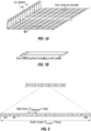
- FIG. 6 is a block diagram of an exemplary MTC device 50, according to exemplary embodiments.
- the MTC device 50 may in some embodiments be a mobile device that is configured for machine-to-machine (M2M) and/or MTC.
- M2M machine-to-machine
- the MTC device 50 in general (it is noted that in 3GPP LTE MTC device 50 can be considered a specific type of UE) comprises a processing module 30 that controls the operation thereof.
- the processing module 30 is connected to a receiver or transceiver module 32 with associated antenna(s) 34 which are used to receive signals from or both transmit signals to and receive signals from a base station 10 in the network 2.
- the processing module 30 can be configured to deactivate the receiver or transceiver module 32 for specified lengths of time.
- the MTC device 50 can also each include a memory module 36 that is connected to the processing module 30 and that stores program and other information and data required for the operation thereof.
- MTC device 50 can be referred to as "MTC UE” or a "UE.”
- the non-MTC wireless device 12 can also be referred to as a "UE”.
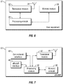
- FIG. 7 shows a block diagram of wireless network node 10 (for example a NodeB or an eNodeB (“eNB”)), also referred to herein as a "base station 10," that can be used in example embodiments described.
- eNB eNodeB
- the wireless radio work node 10 comprises a processing module 40 that controls the operation of the wireless radio work node 10.
- the processing module 40 is connected to a transceiver module 42 with associated antenna(s) 44 which are used to transmit signals to, and receive signals from, UEs 12 and MTC devices 50 in the network.
- the wireless radio work node 10 also comprises a memory module 46 that is connected to the processing module 40 and that stores program and other information and data required for the operation of the base station 10.
- the wireless radio work node 10 also includes components and/or circuitry 48 for allowing the wireless radio work node 10 to exchange information with other wireless radio work nodes 10 (for example via an X2 interface) and components and/or circuitry 49 for allowing the wireless radio work node 10 to exchange information with nodes in the core network.
- base stations for use in other types of network e.g. UTRAN or WCDMA RAN
- Embodiments described herein provide methods, stations and systems for enabling resource allocation for Rel-13 MTC UE 50 with a reduced RF bandwidth, with respect to the network bandwidth.
- the Rel-13 MTC UE 50 is assumed to transmit and receive with a reduced RF bandwidth of 1.4 MHz within any system bandwidth greater than or equal to 1.4 MHz.
- the disclosure proposes the following:
- Subchannel definition for both central subchannel and off- center subchannels Methods of mapping a subcarrier to the DC of a MTC receiver for off-center subchannels; Method of mapping the center frequency of off-center subchannels to a frequency in-between two subcarriers to avoid colliding a subcarrier with the DC in a MTC receiver; and Definition of subchannel to satisfy the 100 kHz raster.
- Subchannel definition and resource allocation to avoid conflict with existing PUCCH resources Subchannel definition and resource allocation to avoid conflict with existing PUCCH resources; and UL subchannel definition as related to DL subchannel definition in FDD and TDD system.
- the proposed methods and systems provide the physical layer resource structure to enable downlink and uplink operation of a Rel-13 MTC UE 50, according to exemplary embodiments.
- the methods allow coexistence of MTC UE 50 with non-MTC UEs 12 in a cell that may use any LTE system bandwidth, for example.
- MTC UE 50 refers to a LTE Rel-13 MTC UE 50 which operates with a reduced RF bandwidth of 1.4 MHz, for example, in both uplink and downlink.
- the 1.4 MHz can reside within any wider system bandwidth that the eNB 10 is using for the cell. It is noted that 1.4 MHz is used herein as a reduced bandwidth, with respect to an overall system bandwidth; however, various other reduced bandwidths may be similarly employed.
- the DL system bandwidth may be divided into a number of DL MTC subchannels, each can be used for serving a MTC UE 50 with 1.4MHz Rx bandwidth.
- Each DL subchannel can be defined by a frequency offset from the center of the system bandwidth (i.e. the carrier frequency).
- FIGs. 8 and 9 are two examples of mapping MTC subchannels in a 10MHz and 5MHz systems, respectively.
- Subchannel 0 is centered at the system bandwidth, and is needed for PSS/SSS/PBCH acquisitions and adjacent cell measurements.
- Other subchannels are off-center subchannels, and can be defined to provide additional system capacity for MTC UEs 50 as well as frequency diversity if a MTC UE 50 is configured to use different subchannels at different times.
- a subchannel be any of the 1.4 MHz reduced bandwidth (BW) on which the Rel-13 MTC UE 50 can operate.
- subchannel 0 be the 1.4 MHz-wide subchannel that is centered at the central carrier frequency of the system BW. Note the indexing of the subchannels used here is for illustration only, and one of skill in the art would realize that there are other equivalent ways to define the indices of the subchannels.
- the central subchannel, subchannel0 always covers the central 72 subcarriers, so that the MTC UE 50 can receive PSS/SSS/PBCH from the eNB.
- the central 72 subcarrier may or may not constitute 6 PRBs.
- Subchannel 0 includes two halves of PRB at the higher and lower end of the 1.4 MHz.
- the maximum number of whole PRBs in Subchannel 0 that can be allocated to the MTC UE is 5 PRBs.
- the two halves PRBs do not need to be left vacant, since the eNB can use those PRBs towards other UEs which include: (a) UEs 12 that are not MTC UE 50; (b) MTC UE 50 that operate on subchannels other than Subchannel 0; (c) MTC UEs 50 that are capable of receiving fractional PRB(s).
- Table 1 for the defined LTE system bandwidths.
- Table 1 PRBs occupied by Subchannel 0 System BW (MHz) N RB DL Indices of PRBs occupied by Subchannel 0 Whole PRBs allocable to MTC UE 50 1.4 6 #0 - #5 #0 - #5 (6 PRBs) 3 15 Half of PRB #4, #5 - #9, half of PRB #10 #5 - #9 ( 5 PRBs ) 5 25 Half of PRB #9, #10 - #14, half of PRB #15 #10 - #14 ( 5 PRBs ) 10 50 #22 - #27 #22 - #27 (6 PRBs) 15 75 Half of PRB #34, #35 - #39, half of PRB #40 #35 - #39 ( 5 PRBs ) 20 100 #47 - #52 #47 - #52 (6 PRBs)
- Subchannel 0 has to be aligned in the central 72 subcarrier of the system bandwidth, the definition of MTC subchannels other than subchannel 0 can be flexible.
- One option is to define non-overlapping consecutive subchannels. This is illustrated in FIG. 8 for system bandwidth of 10 MHz, and in FIG. 9 for system bandwidth of 5 MHz. Note that for the 5 MHz system, since PRB #9 and #15 cannot be allocated to MTC UE of subchannel 0, PRB #9 and #15 can be defined to be part of subchannel 1 and 2, respectively. Since most system bandwidths do not have N RB DL that is a multiple of 6 (PRB), defining consecutive non-overlapping subchannels will make it impossible to allocate some PRBs to the MTC UE 50, such as the PRBs at the highest and lowest ends of the BW in FIGs. 8 and 9 .
- Another option is to define subchannels that are not consecutive, i.e. they can overlap in RBs.
- An example of such definition of MTC subchannels in a 5MHz system is shown in FIG. 10 , where subchannel #0 overlaps with subchannels #2 and #3.
- Defining overlapping Subchannels has the advantage of a larger number of total subchannels, thus allowing more flexibility in DL PRB allocation. Since most system bandwidths do not have N RB DL that is a multiple of 6 (PRB), defining non-consecutive and/or overlapping subchannels makes it possible to assign any PRB in the system to a MTC UE 50.
- PRB multiple of 6
- the MTC UE 50 with direct down conversion receiver receive a DL subchannel that is not centered at the system BW, one of the subcarriers in the subchannel can end up in the Direct Current (DC) in the received BW of the MTC UE 50, which is referred here as the shifted "DC" subcarrier. Since large DC signals can also be generated by other receiver imperfections such as local oscillator (LO) leakage, it is difficult to decode any information carried on the shifted DC subcarrier.
- a subchannel is an off-center subchannel with respect to the system bandwidth if the subchannel is not centered at the system BW, and the DC subcarrier of the subchannel does not coincide with the DC subcarrier of the system bandwidth.
- the shifted DC is located in the middle of a PRB, then only 5 whole PRBs are allocable to the MTC UE 50. This is illustrated with an example in FIG. 11 , where PRB #0 and #6 are not usable as whole PRBs towards the MTC UE 50.
- the shifted DC is located at the lowest or highest subcarrier of a PRB, which allows the MTC to be able to receive full 6 PRBs.
- the option with the shifted DC located at the lowest subcarrier of a PRB is illustrated in FIGS. 12(a) and (b) (configuration A), while the option with the shifted DC located at the highest subcarrier of a PRB is illustrated in FIGs. 13(a) and (b) (configuration B).
- the subcarrier corresponding to the shifted DC is not receivable by the MTC UE 50 operating in that subchannel.
- common signals such as CRS can still be transmitted over the shifted DC and be received by other UEs, but those common signals are not received by the MTC UE 50.
- the corresponding PRB Due to the removal of the shifted DC, the corresponding PRB only has 11 subcarriers that are usable for carrying either EPDCCH or PDSCH to the MTC UE 50.
- the REs of the shifted DC can be viewed as punctured, so that the rate matching and resource mapping procedure do not need to be changed.
- mechanisms such as lower modulation and coding rate can be used by the scheduler.
- Configuration A or Configuration B can be predefined or configured via RRC signaling, for example. If configurable, the eNB 10 can signal to MTC UE 50 whether it should use Configuration A or Configuration B in a static or semi-static fashion. This gives the eNB 10 flexibility in how to schedule EPDCCH/PDSCH, and what transmission mode (TM) to use for PDSCH, etc.
- TM transmission mode
- the configuration is pre-defined.
- Configuration A and Configuration B for the MTC UE 50, the layout of reference signals in a PRB needs to be considered as the shifted DC will make all REs coincides with the shifted DC not receivable.
- Configuration A and Configuration B for the MTC UE 50, the layout of reference signals in a PRB needs to be considered as the shifted DC will make all REs coincides with the shifted DC not receivable.
- eNB may send reference signals to the eNB in a PRB, including but not limited to:
- One exemplary method of shifted DC designation is to always use a same configuration for all cells and all subchannels.
- the highest indexed subcarrier in a PRB includes REs for transmitting DMRS port 7,8,107 and 108.
- making DC subcarrier to be the lowest-indexed subcarrier in PRB #3 in the subchannel is preferred ( FIGs. 12(a) and (b) , configuration A).
- the rule of using Configuration A or Configuration B is predefined, but different configurations can be used depending on the scenario. For example, different cells may use different configurations. For example, to protect CRS reception, it can be defined that the shifted DC is implicitly linked to either Configuration A or Configuration B depending on the cell ID to avoid CRS being in the DC subcarrier.
- k and l are the subcarrier and OFDM symbol index, respectively.
- a pre-defined cell ID dependent rule can be constructed to avoid puncturing port 5 DMRS due to the shifted DC.
- the eNB 10 can schedule higher-priority channel to a PRB that does not contain the shifted DC, while a lower-priority channel can be allocated to the PRB containing the shifted PRB.
- EPDCCH is always allocated to PRBs that do not contain the shifted DC, so that the DMRS for EPDCCH is always receivable by the MTC UE 50.
- the eNB 10 never schedule any transmission in the PRB containing the shifted DC. This avoids the problems brought by the shifted DC, at the expense of reduced resource for MTC UE 50.
- the PRB can still be scheduled to other non-MTC UEs 12.
- the MTC UE 50 tunes its receiving carrier frequency to an existing subcarrier of an off-the-center subchannel. While this is simple for UE 50 implementation in terms of frequency tuning step size and in dealing with DC offsets, an alternative is to build the UE 50 such that it can tune to a frequency that is at the boundary of two adjacent subcarriers.
- An example is shown in FIG. 15 . This would allow the full PRB resources to be used for data scheduling to a MTC UEs. There is no eNB 10 scheduling restriction at the eNB 10. The drawback is that the two subcarriers adjacent to the DC could be attenuated by the DC filter at the MTC receiver. In other words, a tighter (narrower) DC filter may be required at the MTC receiver.
- a DC filtering example is shown in FIG. 16 .
- a frequency shift of half subcarrier spacing is needed during FFT processing at the MTC UE 50 receiver when it is tuned to off-center subchannels.
- the frequency domain symbol in the middle is not skipped.
- the frequency domain symbol in the middle (corresponding to DC of system BW) is intentionally skipped, and the receiver operates as in the existing implementation.
- the UE 12/50 is only required to perform cell search over a 100 KHz raster, according to certain embodiments.
- the carrier center frequency must be an integer multiple of 100 kHz in all bands. If the MTC UE 50 implementation is not designed to be able to tune to other frequencies, then this will limit the location of the subchannels.
- the MTC DC subcarrier is not always mapped to the same subcarrier within a PRB.
- the shifted center carrier frequency will be located in the middle of a PRB.
- An example is shown in FIG. 17 for a 5MHz system.
- F' c > F c or F' c ⁇ F c different subcarrier within the PRB will be mapped to the DC of a MTC receiver and thus is punctured at the eNB.
- F' c > F c subcarrier 5 of the center RB will be punctured
- F' c ⁇ F c subcarrier 6 of the center RB will be punctured.
- the subcarrier index in a PRB is shown in FIG. 14 .
- the Rel-13 MTC UE 50 is only designed to transmit with 1.4 MHz bandwidth, according to the present example - the same as DL. Thus there is also a need to define UL subchannels, similar to DL subchannels.
- the MTC UE 50 UL transmission does not overlap with other legacy UE's 12UL transmission especially the PUCCH at the edge of the UL BW.
- a PUCCH is transmitted on two PRBs, one at the top of the frequency band in one slot and the other at the bottom of the frequency band in the other slot of the same subframe.
- a MTC UE 50 needs to switch frequency between the two slots. This cannot be done as it requires a guard time period (except when the system BW is 1.4 MHz also).
- the UL subchannel is never defined to overlap with the PRBs that can be potentially used for PUCCH transmission by legacy UEs 12.
- a simple solution is that the UL subchannels are never defined to use the top m and bottom m PRBs, where m is a sufficiently large integer. This is illustrated in FIG. 18 .
- the subchannel can be defined to overlap with the PRBs that are potentially used for PUCCH transmission of legacy UEs 12. But PUCCH transmissions of legacy UEs 12 are protected via eNB 10 scheduling decision. This is illustrated in FIG. 19 .
- the eNB 10 schedules MTC UE 50 PUSCH such that it does not overlap with PRBs that are used for PUCCH of other UEs 12 in the same subframe.
- MTC UE 50 PUCCH For MTC UE 50 PUCCH, it can be pre-defined such that the PRBs for MTC UE 50 PUCCH never overlap with PRBs for PUCCH of other UEs 12. For example, the MTC UE 50 PUCCH never uses the band edge PRB(s).
- the subchannels can be any consecutive 6 PRBs.
- the UL subchannels may be defined with or without implicit relationship between UL and DL subchannels.
- the UL subchannel can be uncorrelated with the DL subchannel as a large guard time is needed anyway for switching between DL and UL.
- the guard time can be defined to provide enough time for tuning to a frequency that is different from the previous subframe.
- UL can have various differences, including the following: Unlike in the DL, the MTC UE 50 does not have to tune to the central 72 subcarriers of the system even during initial access.
- the center carrier frequency for the UL subchannel also has to be located at carrier frequencies that are multiples of 900kHz (or 5 PRBs) away from the carrier frequency F c of the system. In that case, the whole PRBs available for UL scheduling are also constrained to 5 PRBs for systems with BW of ⁇ 3, 5, 15 ⁇ MHz.
- the UL subchannel is the same as the DL subchannel at any time. This could save switching time for UL-to-DL switch and DL-to-UL switch and thus there is no need to introduce additional guard time for MTC UEs 50.
- a MTC UL subchannel may be allocated to a different frequency from the DL subchannel.
- additional guard time is needed to allow a MTC UE 50 to switch between DL and UL. This can be done through redefining timing of DL and UL scheduling and HARQ, e.g. the delay from receiving a UL grant to UL transmission or the delay from receiving a DL data to sending an Ack/Nack in the UL.
- FIG. 20 is an exemplary flowchart illustrating a method of operating a wireless device in a wireless network.
- the wireless network node 10 is configured to determine a subchannel within a system bandwidth of the wireless network, using processing module 40.
- the subchannel can be an off-center subchannel with respect to the system bandwidth, and the subchannel can include a plurality of consecutive subcarriers taken from one or more contiguous PRBs.
- the processing module 40 of wireless network node 10 can further map the subchannel's center frequency to a subcarrier of a PRB included in the subchannel.
- the center frequency can correspond to a DC subcarrier at a receiver (e.g., transceiver module 32 of associated with the wireless device (e.g., MTC UE 50).
- a receiver e.g., transceiver module 32 of associated with the wireless device (e.g., MTC UE 50).
- the process moves to operation 220, where the wireless network node 10 can then allocate the subchannel to the MTC UE 50.
- the subchannel allocation can be via RRC signaling, or via physical layer indication.
- RRC signaling or via physical layer indication.
- a physical channel can be scheduled to one or more subcarriers of the subchannel, where the one or more subcarriers do not include the DC subcarrier.
- a physical channel can be scheduled to one or more subcarriers of the subchannel, where the one or more subcarriers include the DC subcarrier, and rate matching can be performed on the physical channel bits to account for the DC subcarrier.
- a UE can be allowed to transmit and receive with a reduced RF bandwidth, in an LTE system with a wider system bandwidth.
- the terms “comprise”, “comprising”, “comprises”, “include”, “including”, “includes”, “have”, “has”, “having”, or variants thereof are open-ended, and include one or more stated features, integers, elements, steps, components or functions but does not preclude the presence or addition of one or more other features, integers, elements, steps, components, functions or groups thereof.
- the common abbreviation “e.g.”, which derives from the Latin phrase “exempli gratia” may be used to introduce or specify a general example or examples of a previously mentioned item, and is not intended to be limiting of such item.
- the common abbreviation “i.e.”, which derives from the Latin phrase “id est,” may be used to specify a particular item from a more general recitation.
- Example embodiments are described herein with reference to block diagrams and/or flowchart illustrations of computer-implemented methods, apparatus (systems and/or devices) and/or computer program products. It is understood that a block of the block diagrams and/or flowchart illustrations, and combinations of blocks in the block diagrams and/or flowchart illustrations, can be implemented by computer program instructions that are performed by one or more computer circuits.
- These computer program instructions may be provided to a processor circuit of a general purpose computer circuit, special purpose computer circuit, and/or other programmable data processing circuit to produce a machine, such that the instructions, which execute via the processor of the computer and/or other programmable data processing apparatus, transform and control transistors, values stored in memory locations, and other hardware components within such circuitry to implement the functions/acts specified in the block diagrams and/or flowchart block or blocks, and thereby create means (functionality) and/or structure for implementing the functions/acts specified in the block diagrams and/or flowchart block(s).
- the functions/acts noted in the blocks may occur out of the order noted in the flowcharts.
- two blocks shown in succession may in fact be executed substantially concurrently or the blocks may sometimes be executed in the reverse order, depending upon the functionality/acts involved.
- the functionality of a given block of the flowcharts and/or block diagrams may be separated into multiple blocks and/or the functionality of two or more blocks of the flowcharts and/or block diagrams may be at least partially integrated.
- other blocks may be added/inserted between the blocks that are illustrated, and/or blocks/operations may be omitted.
- some of the diagrams include arrows on communication paths to show a primary direction of communication, it is to be understood that communication may occur in the opposite direction to the depicted arrows.
Claims (16)
- Verfahren zum Betreiben einer drahtlosen Vorrichtung in einem drahtlosen Netzwerk, wobei die drahtlose Vorrichtung einen Empfänger umfasst, und das Verfahren umfasst:Bestimmen eines Unterkanals innerhalb einer Systembandbreite des drahtlosen Netzwerks, wobeider Unterkanal ein außermittiger Unterkanal in Bezug auf die Systembandbreite ist, undder Unterkanal eine Mehrzahl von aufeinanderfolgenden Unterträgern umfasst, die einem oder mehreren benachbarten physikalischen Ressourcenblöcken, PRB, entnommen sind;Zuordnen der Mittenfrequenz des Unterkanals zu einem Unterträger niedrigster oder höchster Frequenz eines PRBs, der im Unterkanal enthalten ist, wobei die Mittenfrequenz einem Gleichstrom, DC,-Unterträger am Empfänger entspricht; undZuweisen des Unterkanals zur drahtlosen Vorrichtung durch einen drahtlosen Netzwerkknoten.
- Verfahren nach Anspruch 1, wobei das Zuweisen ein Signalisieren unter Verwendung von Funkressourcensteuerungs, RRC,-Signalisierung oder durch Bitübertragungsschichtanzeige an die drahtlose Vorrichtung umfasst.
- Verfahren nach Anspruch 1, wobei das Zuordnen vordefiniert ist.
- Verfahren nach Anspruch 3, wobei das vordefinierte Zuordnen für alle Unterkanäle, die der drahtlosen Vorrichtung innerhalb der Systembandbreite zugewiesen werden können, gleich ist, wobei das vordefinierte Zuordnen zwischen Unterkanälen innerhalb der Systembandbreite variiert oder das vordefinierte Zuordnen eine Funktion einer Kennung des drahtlosen Netzwerkknotens ist.
- Verfahren nach Anspruch 1, ferner umfassend:Disponieren eines physikalischen Kanals für einen oder mehrere Unterträger des Unterkanals, wobei der eine oder die mehreren Unterträger nicht den DC-Träger umfassen; oderDisponieren eines physikalischen Kanals für einen oder mehrere Unterträger des Unterkanals, wobei der eine oder die mehreren Unterträger den DC-Unterträger umfassen, und Durchführen von Ratenanpassung an den Bits des physikalischen Kanals, um den DC-Unterträger zu berücksichtigen.
- Drahtloser Netzwerkknoten in einem drahtlosen Netzwerk, der zum Zuweisen von Ressourcen für eine drahtlose Vorrichtung mit einer reduzierten Hochfrequenz, HF,-Bandbreite konfiguriert ist, wobei die drahtlose Vorrichtung einen Empfänger umfasst, und der drahtlose Netzwerkknoten umfasst:ein Verarbeitungsmodul, das zum Bestimmen eines Unterkanals innerhalb einer Systembandbreite des drahtlosen Netzwerks konfiguriert ist, wobeider Unterkanal ein außermittiger Unterkanal in Bezug auf die Systembandbreite ist, undder Unterkanal eine Mehrzahl von aufeinanderfolgenden Unterträgern umfasst, die einem oder mehreren benachbarten physikalischen Ressourcenblöcken, PRB, entnommen sind;ein Zuordnungsmodul, das so konfiguriert ist, dass es die Mittenfrequenz des Unterkanals zu einem Unterträger niedrigster oder höchster Frequenz eines PRBs zuordnet, der im Unterkanal enthalten ist, wobei die Mittenfrequenz einem Gleichstrom, DC,-Unterträger am Empfänger entspricht; undein Zuweisungsmodul, das zum Zuweisen des Unterkanals zur drahtlosen Vorrichtung konfiguriert ist.
- Drahtloser Netzwerkknoten nach Anspruch 6, wobei das Zuweisungsmodul ferner zum Signalisieren des zugewiesenen Unterkanals unter Verwendung von Funkressourcensteuerungs, RRC,-Signalisierung oder durch eine Bitübertragungsschichtanzeige an die drahtlose Vorrichtung konfiguriert ist.
- Drahtloser Netzwerkknoten nach Anspruch 6, wobei das Zuordnen, das durch das Zuordnungsmodul durchgeführt wird, vordefiniert ist.
- Drahtloser Netzwerkknoten nach Anspruch 8, wobei das vordefinierte Zuordnen für alle Unterkanäle, die der drahtlosen Vorrichtung innerhalb der Systembandbreite zugewiesen werden können, gleich ist, wobei das vordefinierte Zuordnen zwischen Unterkanälen innerhalb der Systembandbreite variiert, oder das vordefinierte Zuordnen eine Funktion einer Kennung des drahtlosen Netzwerkknotens ist.
- Drahtloser Netzknoten nach Anspruch 6, ferner umfassend:ein Dispositionsmodul, das zum Disponieren eines physikalischen Kanals für einen oder mehrere Unterträger des Unterkanals konfiguriert ist, wobei der eine oder die mehreren Unterträger nicht den DC-Träger umfassen; oderein Dispositionsmodul, das so konfiguriert ist, dass es einen physikalischen Kanal für einen oder mehrere Unterträger des Unterkanals disponiert, wobei der eine oder die mehreren Unterträger den DC-Unterträger umfassen, und Ratenanpassung an den Bits des physikalischen Kanals durchführt, um den DC-Unterträger zu berücksichtigen.
- Nicht-transitorisches computerlesbares Medium, das Anweisungen darauf speichert, die bei Ausführung durch einen Prozessor den Prozessor zum Durchführen eines Verfahrens zur Zuweisung von Ressourcen für eine drahtlose Vorrichtung mit einer reduzierten Hochfrequenz, HF,-Bandbreite veranlassen, wobei die drahtlose Vorrichtung einen Empfänger umfasst, und das Verfahren umfasst:Bestimmen eines Unterkanals innerhalb einer Systembandbreite eines drahtlosen Netzwerks, wobeider Unterkanal ein außermittiger Unterkanal in Bezug auf die Systembandbreite ist, undder Unterkanal eine Mehrzahl von aufeinanderfolgenden Unterträgern umfasst, die einem oder mehreren benachbarten physikalischen Ressourcenblöcken, PRB, entnommen sind;Zuordnen der Mittenfrequenz des Unterkanals zu einem niedrigsten oder höchsten Unterträger eines PRBs, der im Unterkanal enthalten ist, wobei die Mittenfrequenz einem Gleichstrom, DC,-Unterträger am Empfänger entspricht; undZuweisen des Unterkanals zur drahtlosen Vorrichtung.
- Benutzereinrichtung, UE, mit reduzierter Hochfrequenz, HF,-Bandbreite in einem drahtlosen Netzwerk, umfassend:
ein Empfangsmodul, das zum Empfangen eines zugewiesenen Unterkanals innerhalb einer Systembandbreite des drahtlosen Netzwerks konfiguriert ist, wobeider Unterkanal ein außermittiger Unterkanal in Bezug auf die Systembandbreite ist,der Unterkanal eine Mehrzahl von aufeinanderfolgenden Unterträgern umfasst, die einem oder mehreren benachbarten physikalischen Ressourcenblöcken, PRB, entnommen sind, unddie Mittenfrequenz des Unterkanals zu einem niedrigsten oder höchsten Unterträger eines PRBs zugeordnet wird, der im Unterkanal enthalten ist, wobei die Mittenfrequenz einem Gleichstrom, DC,-Unterträger entspricht, der mit der UE assoziiert ist. - UE nach Anspruch 12, wobei der zugewiesene Unterkanal durch Funkressourcensteuerungs, RRC,-Signalisierung oder Bitübertragungsschichtanzeige identifiziert wird.
- UE nach Anspruch 12, wobei das Zuordnen vordefiniert ist.
- UE nach Anspruch 14, wobei das vordefinierte Zuordnen für alle Unterkanäle, die der UE innerhalb der Systembandbreite zugewiesen werden können, gleich ist, wobei die vordefinierte Zuordnung zwischen Unterkanälen innerhalb der Systembandbreite variiert oder die vordefinierte Zuordnung eine Funktion einer Kennung eines drahtlosen Netzwerkknotens ist.
- UE nach Anspruch 12, wobei
ein physikalischer Kanal für einen oder mehrere Unterträger des Unterkanals disponiert wird, wobei der eine oder die mehreren Unterträger den DC-Träger umfassen; oder
Ratenanpassung an den Bits des physikalischen Kanals durchgeführt wird, um den DC-Unterträger zu berücksichtigen.
Applications Claiming Priority (3)
| Application Number | Priority Date | Filing Date | Title |
|---|---|---|---|
| US201462047756P | 2014-09-09 | 2014-09-09 | |
| US14/506,289 US10440710B2 (en) | 2014-09-09 | 2014-10-03 | Resource structure and indication for Rel-13 MTC UE |
| PCT/IB2015/056674 WO2016038510A1 (en) | 2014-09-09 | 2015-09-02 | Resource allocation for mtc devices in a lte rel-13 communications system |
Publications (2)
| Publication Number | Publication Date |
|---|---|
| EP3192203A1 EP3192203A1 (de) | 2017-07-19 |
| EP3192203B1 true EP3192203B1 (de) | 2018-08-22 |
Family
ID=55438542
Family Applications (1)
| Application Number | Title | Priority Date | Filing Date |
|---|---|---|---|
| EP15771280.3A Active EP3192203B1 (de) | 2014-09-09 | 2015-09-02 | Ressourcenzuweisung für mtc-geräte in einem kommunikationssytem nach lte-rel-13-standard |
Country Status (7)
| Country | Link |
|---|---|
| US (1) | US10440710B2 (de) |
| EP (1) | EP3192203B1 (de) |
| JP (1) | JP6473804B2 (de) |
| CN (1) | CN107078892B (de) |
| AR (1) | AR101796A1 (de) |
| PH (1) | PH12017500412A1 (de) |
| WO (1) | WO2016038510A1 (de) |
Families Citing this family (37)
| Publication number | Priority date | Publication date | Assignee | Title |
|---|---|---|---|---|
| US10382270B2 (en) * | 2014-09-25 | 2019-08-13 | Lg Electronics Inc. | Method and MTC device for receiving downlink channel |
| US10064181B2 (en) * | 2014-10-03 | 2018-08-28 | Intel IP Corporation | Sub-band allocation techniques for reduced-bandwidth machine-type communication (MTC) devices |
| US10200872B2 (en) * | 2014-10-08 | 2019-02-05 | Qualcomm Incorporated | DC subcarrier handling in narrowband devices |
| US20160127936A1 (en) * | 2014-11-05 | 2016-05-05 | Debdeep CHATTERJEE | User equipment and methods for csi measurements with reduced bandwidth support |
| WO2016099057A1 (ko) * | 2014-12-16 | 2016-06-23 | 엘지전자 주식회사 | 상향링크 데이터의 복조를 위한 dmrs를 전송하는 방법 및 mtc 기기 |
| US10455544B2 (en) | 2015-01-30 | 2019-10-22 | Qualcomm Incorporated | Enhanced paging procedures for machine type communications (MTC) |
| KR102323798B1 (ko) * | 2015-07-16 | 2021-11-09 | 삼성전자 주식회사 | 무선 통신 시스템에서 단말의 하향링크 수신 방법 및 장치 |
| US10516510B2 (en) * | 2015-11-11 | 2019-12-24 | Telefonaktiebolaget Lm Ericsson (Publ) | Method and apparatus for wireless communication |
| CN107294684B (zh) | 2016-04-01 | 2021-07-09 | 夏普株式会社 | 配置非锚物理资源块的方法和基站、确定非锚物理资源块位置的方法和用户设备 |
| US10524255B2 (en) | 2016-05-20 | 2019-12-31 | Lg Electronics Inc. | Method and apparatus for handling DC subcarrier in NR carrier in wireless communication system |
| WO2018021676A1 (en) * | 2016-07-27 | 2018-02-01 | Lg Electronics Inc. | Method and apparatus for handling dc subcarrier in nr carrier in wireless communication system |
| CN109565407B (zh) | 2016-08-07 | 2021-11-16 | Lg电子株式会社 | 用于在窄带无线通信系统中建立扩展窄带的方法及其设备 |
| CN107734561B (zh) | 2016-08-11 | 2021-12-03 | 株式会社Kt | 用于在无线通信系统中配置无线资源的方法和装置 |
| KR101945107B1 (ko) | 2016-08-11 | 2019-02-08 | 주식회사 케이티 | 무선 통신 시스템에서 무선 자원을 구성하는 방법 및 그 장치 |
| US10237826B2 (en) | 2016-09-27 | 2019-03-19 | Intel Corporation | Utilizing DC nulls in transmission of low power wake-up packets |
| US20180092036A1 (en) * | 2016-09-28 | 2018-03-29 | Intel Corporation | Multiplexing scheme to transmit narrowband wake up packets and narrowband beacons within 802.11ax ofdma allocations |
| US10367672B2 (en) * | 2016-09-28 | 2019-07-30 | Qualcomm Incorporated | Enhancements to phase-noise compensation reference signal design and scrambling |
| CN106788931B (zh) | 2016-09-30 | 2019-01-04 | 展讯通信(上海)有限公司 | 通信系统中信息传输的方法及基站、用户设备 |
| US10512050B2 (en) | 2016-10-07 | 2019-12-17 | Qualcomm Incorporated | Synchronization and broadcast channel design with flexible bandwidth allocations |
| US11096128B2 (en) | 2016-11-03 | 2021-08-17 | Qualcomm Incorporated | Techniques for signaling and channel design in new radio |
| CN112332966A (zh) * | 2016-11-27 | 2021-02-05 | 上海朗帛通信技术有限公司 | 一种无线通信中的方法和装置 |
| CN108282283B (zh) * | 2017-01-05 | 2023-04-18 | 华为技术有限公司 | 资源映射方法及用户设备 |
| WO2018172403A1 (en) * | 2017-03-24 | 2018-09-27 | Sony Corporation | Apparatus and method for a mobile telecommunications system |
| US11272510B2 (en) * | 2017-05-19 | 2022-03-08 | Qualcomm Incorporated | Channel and sync raster signaling |
| US10693698B2 (en) * | 2017-06-21 | 2020-06-23 | Qualcomm Incorporated | Techniques for carrier sharing between radio access technologies |
| US10959258B2 (en) * | 2017-06-22 | 2021-03-23 | Telefonaktiebolaget Lm Ericsson (Publ) | Transmission allocation control |
| EP3653010B1 (de) * | 2017-08-10 | 2023-06-07 | Samsung Electronics Co., Ltd. | Verfahren und vorrichtung zur bestimmung von frequenzressourcen in zellularen netzwerken der nächsten generation |
| US11363493B2 (en) * | 2017-08-23 | 2022-06-14 | Qualcomm Incorporated | Carrier aggregation configurations in wireless systems |
| CN109475003B (zh) * | 2017-09-08 | 2024-03-29 | 华为技术有限公司 | 一种信号发送、信号接收方法及装置 |
| EP3688916B1 (de) * | 2017-09-28 | 2023-06-07 | Telefonaktiebolaget LM Ericsson (publ) | Übertragungen von sub-physikalischen ressourcenblöcken (sub-prb) über einen physikalischen gemeinsam genutzten uplink-kanal (pusch) |
| CN111713156B (zh) * | 2018-02-07 | 2024-04-12 | 瑞典爱立信有限公司 | 第一网络节点、第二网络节点、第一无线设备和由其执行的用于处理无线通信网络中的载波的方法 |
| US10925078B2 (en) * | 2018-02-16 | 2021-02-16 | Apple Inc. | Two-tone physical uplink shared channel for machine type communications |
| US10868626B2 (en) * | 2018-02-21 | 2020-12-15 | Mediatek Inc. | Synchronization signal block raster shift in mobile communications |
| CN109168146B (zh) * | 2018-11-23 | 2020-04-07 | 西安电子科技大学 | 支持混合授权-非授权频段的mtc传输方法 |
| KR102528624B1 (ko) * | 2019-04-12 | 2023-05-04 | 삼성전자 주식회사 | 무선 통신 시스템에서 로컬 주파수를 결정하는 방법 및 장치 |
| WO2021028885A1 (en) * | 2019-08-15 | 2021-02-18 | Telefonaktiebolaget Lm Ericsson (Publ) | Applicability of lte-m subcarrier puncturing in coexistence with nr |
| EP4108026A4 (de) * | 2020-02-21 | 2024-03-27 | Commscope Technologies Llc | Spektral-effiziente nutzung eines uplink-steuerkanals |
Family Cites Families (9)
| Publication number | Priority date | Publication date | Assignee | Title |
|---|---|---|---|---|
| CN101208887B (zh) * | 2005-03-30 | 2011-07-06 | 北电网络有限公司 | 正交频分多路复用符号的传输方法和系统 |
| GB2436416A (en) * | 2006-03-20 | 2007-09-26 | Nec Corp | Signal resource allocation in a communication system using a plurality of subcarriers |
| CN101635595B (zh) * | 2008-07-24 | 2013-12-04 | 中兴通讯股份有限公司 | 无线资源的子信道化和资源映射方法 |
| US10111224B2 (en) | 2011-09-30 | 2018-10-23 | Interdigital Patent Holdings, Inc. | Device communication using a reduced channel bandwidth |
| KR20130049582A (ko) | 2011-11-04 | 2013-05-14 | 삼성전자주식회사 | 무선 다중 캐리어 시스템에서 자원 할당 방법 및 장치 |
| US9166754B2 (en) * | 2011-11-08 | 2015-10-20 | Industrial Technology Research Institute | Method of handling shortened resource block for machine type communication device and related communication device |
| IN2014CN04550A (de) | 2011-11-25 | 2015-09-18 | Nec Corp | |
| GB2506403B (en) | 2012-09-28 | 2018-01-03 | Sony Corp | Assigning mode of virtual channel operation to mobile terminal |
| US9455810B2 (en) * | 2014-06-26 | 2016-09-27 | Intel IP Corporation | On the definition of the resource block in OFDMA/UL MUMIMO in HEW |
-
2014
- 2014-10-03 US US14/506,289 patent/US10440710B2/en active Active
-
2015
- 2015-09-02 JP JP2017513064A patent/JP6473804B2/ja active Active
- 2015-09-02 EP EP15771280.3A patent/EP3192203B1/de active Active
- 2015-09-02 CN CN201580060839.7A patent/CN107078892B/zh not_active Expired - Fee Related
- 2015-09-02 WO PCT/IB2015/056674 patent/WO2016038510A1/en active Application Filing
- 2015-09-09 AR ARP150102878A patent/AR101796A1/es active IP Right Grant
-
2017
- 2017-03-06 PH PH12017500412A patent/PH12017500412A1/en unknown
Non-Patent Citations (1)
| Title |
|---|
| None * |
Also Published As
| Publication number | Publication date |
|---|---|
| US10440710B2 (en) | 2019-10-08 |
| US20160072614A1 (en) | 2016-03-10 |
| CN107078892A (zh) | 2017-08-18 |
| AR101796A1 (es) | 2017-01-11 |
| WO2016038510A1 (en) | 2016-03-17 |
| JP2017535104A (ja) | 2017-11-24 |
| JP6473804B2 (ja) | 2019-02-20 |
| PH12017500412A1 (en) | 2017-07-17 |
| EP3192203A1 (de) | 2017-07-19 |
| CN107078892B (zh) | 2020-10-23 |
Similar Documents
| Publication | Publication Date | Title |
|---|---|---|
| EP3192203B1 (de) | Ressourcenzuweisung für mtc-geräte in einem kommunikationssytem nach lte-rel-13-standard | |
| US11101950B2 (en) | Demodulation reference signal (DMRS) bundling in slot aggregation and slot format considerations for new radio | |
| US11509372B2 (en) | Capability information for sounding reference signal improvements | |
| US20200028638A1 (en) | Srs resource configuration enhancements | |
| CN111316610A (zh) | 无线通信系统中rmsi coreset配置的方法和装置 | |
| EP3896889A1 (de) | Übertragung von uplink-steuerkanälen über ein unlizenziertes funkfrequenzspektrumsband | |
| US11456896B2 (en) | RRC configuration for aperiodic SRS on additional SRS symbols | |
| RU2742555C1 (ru) | Пользовательский терминал, базовая радиостанция и способ радиосвязи | |
| US10448380B2 (en) | Split symbol control for aligned numerology | |
| KR102465148B1 (ko) | 비면허 대역에서 제어 채널 전송 방법, 장치 및 시스템 | |
| US20180109406A1 (en) | Resource block alignment in mixed numerology wireless communications | |
| CN110740516A (zh) | 用于在免授权频带中发送上行链路信道的方法和装置 | |
| US11129150B2 (en) | Shortened transmission time interval (STTI) configuration for low latency communications | |
| CN110574329B (zh) | 用于低延时通信的下行链路控制信道结构 | |
| US20230353319A1 (en) | Bandwidth operation for full duplex user equipment | |
| KR102564096B1 (ko) | 물리 브로드캐스트 채널을 위한 전용 레퍼런스 신호 | |
| CN112534751B (zh) | 利用时隙聚合的零功率(zp)信道状态信息参考信号(csi-rs)速率匹配 | |
| US11632754B2 (en) | Support of multiple SRS in the same subframe | |
| US20180160405A1 (en) | Rate matching and signaling | |
| WO2018031068A1 (en) | Partial symbol transmission | |
| EP3100397A1 (de) | Senden und empfangen von knoten und verfahren für steuerkanalübertragungen in einem funkkommunikationsnetz | |
| US11882600B2 (en) | Conditional uplink grant in unlicensed spectrum | |
| US20210409160A1 (en) | Hybrid automatic repeat request (harq) process sharing across carriers | |
| CN114175543B (zh) | 跨载波反馈 | |
| KR20180122904A (ko) | 무선 통신시스템의 물리 하향링크 제어 채널 전송 및 수신방법, 장치 및 시스템 |
Legal Events
| Date | Code | Title | Description |
|---|---|---|---|
| STAA | Information on the status of an ep patent application or granted ep patent |
Free format text: STATUS: THE INTERNATIONAL PUBLICATION HAS BEEN MADE |
|
| PUAI | Public reference made under article 153(3) epc to a published international application that has entered the european phase |
Free format text: ORIGINAL CODE: 0009012 |
|
| STAA | Information on the status of an ep patent application or granted ep patent |
Free format text: STATUS: REQUEST FOR EXAMINATION WAS MADE |
|
| 17P | Request for examination filed |
Effective date: 20170308 |
|
| AK | Designated contracting states |
Kind code of ref document: A1 Designated state(s): AL AT BE BG CH CY CZ DE DK EE ES FI FR GB GR HR HU IE IS IT LI LT LU LV MC MK MT NL NO PL PT RO RS SE SI SK SM TR |
|
| AX | Request for extension of the european patent |
Extension state: BA ME |
|
| DAV | Request for validation of the european patent (deleted) | ||
| DAX | Request for extension of the european patent (deleted) | ||
| GRAP | Despatch of communication of intention to grant a patent |
Free format text: ORIGINAL CODE: EPIDOSNIGR1 |
|
| STAA | Information on the status of an ep patent application or granted ep patent |
Free format text: STATUS: GRANT OF PATENT IS INTENDED |
|
| INTG | Intention to grant announced |
Effective date: 20180302 |
|
| GRAS | Grant fee paid |
Free format text: ORIGINAL CODE: EPIDOSNIGR3 |
|
| GRAA | (expected) grant |
Free format text: ORIGINAL CODE: 0009210 |
|
| STAA | Information on the status of an ep patent application or granted ep patent |
Free format text: STATUS: THE PATENT HAS BEEN GRANTED |
|
| AK | Designated contracting states |
Kind code of ref document: B1 Designated state(s): AL AT BE BG CH CY CZ DE DK EE ES FI FR GB GR HR HU IE IS IT LI LT LU LV MC MK MT NL NO PL PT RO RS SE SI SK SM TR |
|
| REG | Reference to a national code |
Ref country code: GB Ref legal event code: FG4D |
|
| REG | Reference to a national code |
Ref country code: CH Ref legal event code: EP |
|
| REG | Reference to a national code |
Ref country code: AT Ref legal event code: REF Ref document number: 1033722 Country of ref document: AT Kind code of ref document: T Effective date: 20180915 |
|
| REG | Reference to a national code |
Ref country code: IE Ref legal event code: FG4D |
|
| REG | Reference to a national code |
Ref country code: DE Ref legal event code: R096 Ref document number: 602015015202 Country of ref document: DE |
|
| REG | Reference to a national code |
Ref country code: FR Ref legal event code: PLFP Year of fee payment: 4 |
|
| REG | Reference to a national code |
Ref country code: NL Ref legal event code: MP Effective date: 20180822 |
|
| REG | Reference to a national code |
Ref country code: LT Ref legal event code: MG4D |
|
| PG25 | Lapsed in a contracting state [announced via postgrant information from national office to epo] |
Ref country code: LT Free format text: LAPSE BECAUSE OF FAILURE TO SUBMIT A TRANSLATION OF THE DESCRIPTION OR TO PAY THE FEE WITHIN THE PRESCRIBED TIME-LIMIT Effective date: 20180822 Ref country code: NL Free format text: LAPSE BECAUSE OF FAILURE TO SUBMIT A TRANSLATION OF THE DESCRIPTION OR TO PAY THE FEE WITHIN THE PRESCRIBED TIME-LIMIT Effective date: 20180822 Ref country code: RS Free format text: LAPSE BECAUSE OF FAILURE TO SUBMIT A TRANSLATION OF THE DESCRIPTION OR TO PAY THE FEE WITHIN THE PRESCRIBED TIME-LIMIT Effective date: 20180822 Ref country code: IS Free format text: LAPSE BECAUSE OF FAILURE TO SUBMIT A TRANSLATION OF THE DESCRIPTION OR TO PAY THE FEE WITHIN THE PRESCRIBED TIME-LIMIT Effective date: 20181222 Ref country code: NO Free format text: LAPSE BECAUSE OF FAILURE TO SUBMIT A TRANSLATION OF THE DESCRIPTION OR TO PAY THE FEE WITHIN THE PRESCRIBED TIME-LIMIT Effective date: 20181122 Ref country code: GR Free format text: LAPSE BECAUSE OF FAILURE TO SUBMIT A TRANSLATION OF THE DESCRIPTION OR TO PAY THE FEE WITHIN THE PRESCRIBED TIME-LIMIT Effective date: 20181123 Ref country code: BG Free format text: LAPSE BECAUSE OF FAILURE TO SUBMIT A TRANSLATION OF THE DESCRIPTION OR TO PAY THE FEE WITHIN THE PRESCRIBED TIME-LIMIT Effective date: 20181122 Ref country code: SE Free format text: LAPSE BECAUSE OF FAILURE TO SUBMIT A TRANSLATION OF THE DESCRIPTION OR TO PAY THE FEE WITHIN THE PRESCRIBED TIME-LIMIT Effective date: 20180822 |
|
| REG | Reference to a national code |
Ref country code: AT Ref legal event code: MK05 Ref document number: 1033722 Country of ref document: AT Kind code of ref document: T Effective date: 20180822 |
|
| PG25 | Lapsed in a contracting state [announced via postgrant information from national office to epo] |
Ref country code: AL Free format text: LAPSE BECAUSE OF FAILURE TO SUBMIT A TRANSLATION OF THE DESCRIPTION OR TO PAY THE FEE WITHIN THE PRESCRIBED TIME-LIMIT Effective date: 20180822 Ref country code: LV Free format text: LAPSE BECAUSE OF FAILURE TO SUBMIT A TRANSLATION OF THE DESCRIPTION OR TO PAY THE FEE WITHIN THE PRESCRIBED TIME-LIMIT Effective date: 20180822 Ref country code: HR Free format text: LAPSE BECAUSE OF FAILURE TO SUBMIT A TRANSLATION OF THE DESCRIPTION OR TO PAY THE FEE WITHIN THE PRESCRIBED TIME-LIMIT Effective date: 20180822 |
|
| PG25 | Lapsed in a contracting state [announced via postgrant information from national office to epo] |
Ref country code: CZ Free format text: LAPSE BECAUSE OF FAILURE TO SUBMIT A TRANSLATION OF THE DESCRIPTION OR TO PAY THE FEE WITHIN THE PRESCRIBED TIME-LIMIT Effective date: 20180822 Ref country code: ES Free format text: LAPSE BECAUSE OF FAILURE TO SUBMIT A TRANSLATION OF THE DESCRIPTION OR TO PAY THE FEE WITHIN THE PRESCRIBED TIME-LIMIT Effective date: 20180822 Ref country code: EE Free format text: LAPSE BECAUSE OF FAILURE TO SUBMIT A TRANSLATION OF THE DESCRIPTION OR TO PAY THE FEE WITHIN THE PRESCRIBED TIME-LIMIT Effective date: 20180822 Ref country code: PL Free format text: LAPSE BECAUSE OF FAILURE TO SUBMIT A TRANSLATION OF THE DESCRIPTION OR TO PAY THE FEE WITHIN THE PRESCRIBED TIME-LIMIT Effective date: 20180822 Ref country code: AT Free format text: LAPSE BECAUSE OF FAILURE TO SUBMIT A TRANSLATION OF THE DESCRIPTION OR TO PAY THE FEE WITHIN THE PRESCRIBED TIME-LIMIT Effective date: 20180822 Ref country code: RO Free format text: LAPSE BECAUSE OF FAILURE TO SUBMIT A TRANSLATION OF THE DESCRIPTION OR TO PAY THE FEE WITHIN THE PRESCRIBED TIME-LIMIT Effective date: 20180822 |
|
| REG | Reference to a national code |
Ref country code: CH Ref legal event code: PL |
|
| REG | Reference to a national code |
Ref country code: DE Ref legal event code: R097 Ref document number: 602015015202 Country of ref document: DE |
|
| PG25 | Lapsed in a contracting state [announced via postgrant information from national office to epo] |
Ref country code: DK Free format text: LAPSE BECAUSE OF FAILURE TO SUBMIT A TRANSLATION OF THE DESCRIPTION OR TO PAY THE FEE WITHIN THE PRESCRIBED TIME-LIMIT Effective date: 20180822 Ref country code: SM Free format text: LAPSE BECAUSE OF FAILURE TO SUBMIT A TRANSLATION OF THE DESCRIPTION OR TO PAY THE FEE WITHIN THE PRESCRIBED TIME-LIMIT Effective date: 20180822 Ref country code: SK Free format text: LAPSE BECAUSE OF FAILURE TO SUBMIT A TRANSLATION OF THE DESCRIPTION OR TO PAY THE FEE WITHIN THE PRESCRIBED TIME-LIMIT Effective date: 20180822 |
|
| REG | Reference to a national code |
Ref country code: BE Ref legal event code: MM Effective date: 20180930 |
|
| PG25 | Lapsed in a contracting state [announced via postgrant information from national office to epo] |
Ref country code: MC Free format text: LAPSE BECAUSE OF FAILURE TO SUBMIT A TRANSLATION OF THE DESCRIPTION OR TO PAY THE FEE WITHIN THE PRESCRIBED TIME-LIMIT Effective date: 20180822 Ref country code: LU Free format text: LAPSE BECAUSE OF NON-PAYMENT OF DUE FEES Effective date: 20180902 |
|
| PLBE | No opposition filed within time limit |
Free format text: ORIGINAL CODE: 0009261 |
|
| STAA | Information on the status of an ep patent application or granted ep patent |
Free format text: STATUS: NO OPPOSITION FILED WITHIN TIME LIMIT |
|
| 26N | No opposition filed |
Effective date: 20190523 |
|
| PG25 | Lapsed in a contracting state [announced via postgrant information from national office to epo] |
Ref country code: BE Free format text: LAPSE BECAUSE OF NON-PAYMENT OF DUE FEES Effective date: 20180930 Ref country code: CH Free format text: LAPSE BECAUSE OF NON-PAYMENT OF DUE FEES Effective date: 20180930 Ref country code: LI Free format text: LAPSE BECAUSE OF NON-PAYMENT OF DUE FEES Effective date: 20180930 Ref country code: SI Free format text: LAPSE BECAUSE OF FAILURE TO SUBMIT A TRANSLATION OF THE DESCRIPTION OR TO PAY THE FEE WITHIN THE PRESCRIBED TIME-LIMIT Effective date: 20180822 |
|
| PG25 | Lapsed in a contracting state [announced via postgrant information from national office to epo] |
Ref country code: MT Free format text: LAPSE BECAUSE OF NON-PAYMENT OF DUE FEES Effective date: 20180902 |
|
| PG25 | Lapsed in a contracting state [announced via postgrant information from national office to epo] |
Ref country code: TR Free format text: LAPSE BECAUSE OF FAILURE TO SUBMIT A TRANSLATION OF THE DESCRIPTION OR TO PAY THE FEE WITHIN THE PRESCRIBED TIME-LIMIT Effective date: 20180822 |
|
| PG25 | Lapsed in a contracting state [announced via postgrant information from national office to epo] |
Ref country code: PT Free format text: LAPSE BECAUSE OF FAILURE TO SUBMIT A TRANSLATION OF THE DESCRIPTION OR TO PAY THE FEE WITHIN THE PRESCRIBED TIME-LIMIT Effective date: 20180822 |
|
| PG25 | Lapsed in a contracting state [announced via postgrant information from national office to epo] |
Ref country code: MK Free format text: LAPSE BECAUSE OF NON-PAYMENT OF DUE FEES Effective date: 20180822 Ref country code: HU Free format text: LAPSE BECAUSE OF FAILURE TO SUBMIT A TRANSLATION OF THE DESCRIPTION OR TO PAY THE FEE WITHIN THE PRESCRIBED TIME-LIMIT; INVALID AB INITIO Effective date: 20150902 Ref country code: CY Free format text: LAPSE BECAUSE OF FAILURE TO SUBMIT A TRANSLATION OF THE DESCRIPTION OR TO PAY THE FEE WITHIN THE PRESCRIBED TIME-LIMIT Effective date: 20180822 |
|
| PGFP | Annual fee paid to national office [announced via postgrant information from national office to epo] |
Ref country code: FI Payment date: 20200929 Year of fee payment: 6 Ref country code: DE Payment date: 20200929 Year of fee payment: 6 Ref country code: IE Payment date: 20200928 Year of fee payment: 6 |
|
| PGFP | Annual fee paid to national office [announced via postgrant information from national office to epo] |
Ref country code: IT Payment date: 20200923 Year of fee payment: 6 |
|
| REG | Reference to a national code |
Ref country code: DE Ref legal event code: R119 Ref document number: 602015015202 Country of ref document: DE |
|
| REG | Reference to a national code |
Ref country code: FI Ref legal event code: MAE |
|
| PG25 | Lapsed in a contracting state [announced via postgrant information from national office to epo] |
Ref country code: FI Free format text: LAPSE BECAUSE OF NON-PAYMENT OF DUE FEES Effective date: 20210902 |
|
| PG25 | Lapsed in a contracting state [announced via postgrant information from national office to epo] |
Ref country code: IE Free format text: LAPSE BECAUSE OF NON-PAYMENT OF DUE FEES Effective date: 20210902 Ref country code: DE Free format text: LAPSE BECAUSE OF NON-PAYMENT OF DUE FEES Effective date: 20220401 |
|
| PG25 | Lapsed in a contracting state [announced via postgrant information from national office to epo] |
Ref country code: IT Free format text: LAPSE BECAUSE OF NON-PAYMENT OF DUE FEES Effective date: 20210902 |
|
| P01 | Opt-out of the competence of the unified patent court (upc) registered |
Effective date: 20230523 |
|
| PGFP | Annual fee paid to national office [announced via postgrant information from national office to epo] |
Ref country code: GB Payment date: 20230927 Year of fee payment: 9 |
|
| PGFP | Annual fee paid to national office [announced via postgrant information from national office to epo] |
Ref country code: FR Payment date: 20230925 Year of fee payment: 9 |