EP3192109B1 - Energiebereitstellungsmodul für eine in einem fahrzeug angeordnete spannungsversorgungsvorrichtung - Google Patents
Energiebereitstellungsmodul für eine in einem fahrzeug angeordnete spannungsversorgungsvorrichtung Download PDFInfo
- Publication number
- EP3192109B1 EP3192109B1 EP15727382.2A EP15727382A EP3192109B1 EP 3192109 B1 EP3192109 B1 EP 3192109B1 EP 15727382 A EP15727382 A EP 15727382A EP 3192109 B1 EP3192109 B1 EP 3192109B1
- Authority
- EP
- European Patent Office
- Prior art keywords
- connection
- cells
- power supply
- energy supply
- transverse
- Prior art date
- Legal status (The legal status is an assumption and is not a legal conclusion. Google has not performed a legal analysis and makes no representation as to the accuracy of the status listed.)
- Active
Links
Images


Classifications
-
- H—ELECTRICITY
- H01—ELECTRIC ELEMENTS
- H01M—PROCESSES OR MEANS, e.g. BATTERIES, FOR THE DIRECT CONVERSION OF CHEMICAL ENERGY INTO ELECTRICAL ENERGY
- H01M10/00—Secondary cells; Manufacture thereof
- H01M10/04—Construction or manufacture in general
- H01M10/0481—Compression means other than compression means for stacks of electrodes and separators
-
- H—ELECTRICITY
- H01—ELECTRIC ELEMENTS
- H01M—PROCESSES OR MEANS, e.g. BATTERIES, FOR THE DIRECT CONVERSION OF CHEMICAL ENERGY INTO ELECTRICAL ENERGY
- H01M10/00—Secondary cells; Manufacture thereof
- H01M10/60—Heating or cooling; Temperature control
- H01M10/65—Means for temperature control structurally associated with the cells
- H01M10/655—Solid structures for heat exchange or heat conduction
- H01M10/6556—Solid parts with flow channel passages or pipes for heat exchange
-
- H—ELECTRICITY
- H01—ELECTRIC ELEMENTS
- H01M—PROCESSES OR MEANS, e.g. BATTERIES, FOR THE DIRECT CONVERSION OF CHEMICAL ENERGY INTO ELECTRICAL ENERGY
- H01M10/00—Secondary cells; Manufacture thereof
- H01M10/60—Heating or cooling; Temperature control
- H01M10/61—Types of temperature control
- H01M10/613—Cooling or keeping cold
-
- H—ELECTRICITY
- H01—ELECTRIC ELEMENTS
- H01M—PROCESSES OR MEANS, e.g. BATTERIES, FOR THE DIRECT CONVERSION OF CHEMICAL ENERGY INTO ELECTRICAL ENERGY
- H01M10/00—Secondary cells; Manufacture thereof
- H01M10/60—Heating or cooling; Temperature control
- H01M10/62—Heating or cooling; Temperature control specially adapted for specific applications
- H01M10/625—Vehicles
-
- H—ELECTRICITY
- H01—ELECTRIC ELEMENTS
- H01M—PROCESSES OR MEANS, e.g. BATTERIES, FOR THE DIRECT CONVERSION OF CHEMICAL ENERGY INTO ELECTRICAL ENERGY
- H01M10/00—Secondary cells; Manufacture thereof
- H01M10/60—Heating or cooling; Temperature control
- H01M10/63—Control systems
-
- H—ELECTRICITY
- H01—ELECTRIC ELEMENTS
- H01M—PROCESSES OR MEANS, e.g. BATTERIES, FOR THE DIRECT CONVERSION OF CHEMICAL ENERGY INTO ELECTRICAL ENERGY
- H01M10/00—Secondary cells; Manufacture thereof
- H01M10/60—Heating or cooling; Temperature control
- H01M10/64—Heating or cooling; Temperature control characterised by the shape of the cells
- H01M10/647—Prismatic or flat cells, e.g. pouch cells
-
- H—ELECTRICITY
- H01—ELECTRIC ELEMENTS
- H01M—PROCESSES OR MEANS, e.g. BATTERIES, FOR THE DIRECT CONVERSION OF CHEMICAL ENERGY INTO ELECTRICAL ENERGY
- H01M50/00—Constructional details or processes of manufacture of the non-active parts of electrochemical cells other than fuel cells, e.g. hybrid cells
- H01M50/20—Mountings; Secondary casings or frames; Racks, modules or packs; Suspension devices; Shock absorbers; Transport or carrying devices; Holders
- H01M50/204—Racks, modules or packs for multiple batteries or multiple cells
- H01M50/207—Racks, modules or packs for multiple batteries or multiple cells characterised by their shape
- H01M50/209—Racks, modules or packs for multiple batteries or multiple cells characterised by their shape adapted for prismatic or rectangular cells
-
- H—ELECTRICITY
- H01—ELECTRIC ELEMENTS
- H01M—PROCESSES OR MEANS, e.g. BATTERIES, FOR THE DIRECT CONVERSION OF CHEMICAL ENERGY INTO ELECTRICAL ENERGY
- H01M50/00—Constructional details or processes of manufacture of the non-active parts of electrochemical cells other than fuel cells, e.g. hybrid cells
- H01M50/20—Mountings; Secondary casings or frames; Racks, modules or packs; Suspension devices; Shock absorbers; Transport or carrying devices; Holders
- H01M50/262—Mountings; Secondary casings or frames; Racks, modules or packs; Suspension devices; Shock absorbers; Transport or carrying devices; Holders with fastening means, e.g. locks
- H01M50/264—Mountings; Secondary casings or frames; Racks, modules or packs; Suspension devices; Shock absorbers; Transport or carrying devices; Holders with fastening means, e.g. locks for cells or batteries, e.g. straps, tie rods or peripheral frames
-
- H—ELECTRICITY
- H01—ELECTRIC ELEMENTS
- H01M—PROCESSES OR MEANS, e.g. BATTERIES, FOR THE DIRECT CONVERSION OF CHEMICAL ENERGY INTO ELECTRICAL ENERGY
- H01M2220/00—Batteries for particular applications
- H01M2220/20—Batteries in motive systems, e.g. vehicle, ship, plane
-
- Y—GENERAL TAGGING OF NEW TECHNOLOGICAL DEVELOPMENTS; GENERAL TAGGING OF CROSS-SECTIONAL TECHNOLOGIES SPANNING OVER SEVERAL SECTIONS OF THE IPC; TECHNICAL SUBJECTS COVERED BY FORMER USPC CROSS-REFERENCE ART COLLECTIONS [XRACs] AND DIGESTS
- Y02—TECHNOLOGIES OR APPLICATIONS FOR MITIGATION OR ADAPTATION AGAINST CLIMATE CHANGE
- Y02E—REDUCTION OF GREENHOUSE GAS [GHG] EMISSIONS, RELATED TO ENERGY GENERATION, TRANSMISSION OR DISTRIBUTION
- Y02E60/00—Enabling technologies; Technologies with a potential or indirect contribution to GHG emissions mitigation
- Y02E60/10—Energy storage using batteries
-
- Y—GENERAL TAGGING OF NEW TECHNOLOGICAL DEVELOPMENTS; GENERAL TAGGING OF CROSS-SECTIONAL TECHNOLOGIES SPANNING OVER SEVERAL SECTIONS OF THE IPC; TECHNICAL SUBJECTS COVERED BY FORMER USPC CROSS-REFERENCE ART COLLECTIONS [XRACs] AND DIGESTS
- Y02—TECHNOLOGIES OR APPLICATIONS FOR MITIGATION OR ADAPTATION AGAINST CLIMATE CHANGE
- Y02P—CLIMATE CHANGE MITIGATION TECHNOLOGIES IN THE PRODUCTION OR PROCESSING OF GOODS
- Y02P70/00—Climate change mitigation technologies in the production process for final industrial or consumer products
- Y02P70/50—Manufacturing or production processes characterised by the final manufactured product
-
- Y—GENERAL TAGGING OF NEW TECHNOLOGICAL DEVELOPMENTS; GENERAL TAGGING OF CROSS-SECTIONAL TECHNOLOGIES SPANNING OVER SEVERAL SECTIONS OF THE IPC; TECHNICAL SUBJECTS COVERED BY FORMER USPC CROSS-REFERENCE ART COLLECTIONS [XRACs] AND DIGESTS
- Y02—TECHNOLOGIES OR APPLICATIONS FOR MITIGATION OR ADAPTATION AGAINST CLIMATE CHANGE
- Y02T—CLIMATE CHANGE MITIGATION TECHNOLOGIES RELATED TO TRANSPORTATION
- Y02T10/00—Road transport of goods or passengers
- Y02T10/60—Other road transportation technologies with climate change mitigation effect
- Y02T10/70—Energy storage systems for electromobility, e.g. batteries
Definitions
- the invention relates to an energy supply module for a voltage supply device arranged in a vehicle.
- This energy supply module is constructed from a large number of structurally independent energy supply cells, which are stacked to form at least one row of cells and are arranged one behind the other.
- the energy supply module interacts with a temperature control device which is designed to temperature control at least some of the energy supply cells by means of a heating medium.
- the energy supply module also has a tensioning device which is designed to tension the energy supply cells of the at least one row of cells, the tensioning device for this purpose having at least two end plates and a tension element, the at least two end plates with the tension element for forming a tensioning force acting on the energy supply cells interact.
- An energy supply module constructed in this way can be contained in a voltage supply device which is arranged in a hybrid vehicle or electric vehicle and with which an electrical machine used as a drive machine in such vehicles is supplied with electrical energy.
- a hybrid vehicle in addition to the electrical machine, another unit is used for the drive, usually a Combustion engine. Whereas an electric vehicle is only powered by an electric machine.
- the electrical machines used are generally designed as internal rotor machines in which a rotatably mounted rotor is enclosed by a stationary stator. Synchronous machines, in particular hybrid synchronous machines, can be used as drive machines.
- a traction battery is an electrical high-voltage storage device that can have a voltage level of 250 to 420 volts.
- a traction battery is constructed from a large number of energy supply cells connected in series, which are preferably designed to be rechargeable.
- the energy supply cells are usually combined or interconnected into smaller groups, the so-called energy supply modules, the energy supply modules being connected in series with one another to form the traction battery.
- a traction battery and thus the energy supply modules or the energy supply cells built into it, are exposed to strong temperature influences or temperature fluctuations in vehicle operation. This is due, on the one hand, to the temperature development in the energy supply cells themselves, which occurs there due to the provision of electrical energy. On the other hand, there are external factors that influence the temperature of the traction battery, such as the seasonal ambient temperature or the location of the vehicle.
- a defined temperature management for the traction battery is necessary for a voltage supply device or the energy supply modules or energy supply cells built into it.
- it is necessary to cool the voltage supply device or the energy supply modules installed in it in order to be able to operate it in an optimal temperature range.
- it may also be necessary to heat the voltage supply device or the energy supply modules installed in it.
- the outer surfaces of the energy supply cells are usually connected with temperature control elements, with which the temperature of the energy supply cells can be adjusted using a heat medium, which can also be referred to as a heat transfer medium.
- these are cooling elements with which the energy can be cooled using a fluid, in particular a liquid.
- the fluid can also be a gas or a mixture or a mixture consisting of at least one gas and at least one liquid.
- refrigerants are so-called two-phase mixtures consisting of at least one gas and at least one liquid.
- These temperature control elements or cooling elements can be designed differently. For example, they can be designed as a cooling plate with internal fluid channels. Alternatively, these elements can be realized using an extruded profile.
- the energy supply cells can be cooled and / or heated.
- the heating medium can also be referred to as a temperature control medium. If the term heating medium is used below, it should be synonymous with the terms heat transfer medium or temperature control medium.
- the temperature control elements or cooling elements have mostly been components or components additionally installed in an energy supply module, which are connected to them in order to achieve effective temperature control or cooling of the energy supply cells by pressing and / or gluing.
- tempering elements or cooling elements only serve to temper or cool the energy supply cells. They take on or have no further function within the energy supply module.
- the fact that the temperature control elements or cooling elements are separate parts or components that do not perform any other function besides temperature control or cooling within an energy supply module has the following disadvantages: On the one hand, there is additional installation space within an energy supply module to provide these "additional" temperature control elements or cooling elements, which is why there is an increased space requirement. The energy supply module could actually be made smaller or more compact. On the other hand, these "additional" temperature control elements or cooling elements cause additional weight, the energy supply module is unnecessarily heavy, it could be made lighter.
- WO 2013/083214 A1 describes a cell block for a battery, with a plurality of series and / or parallel electrically connected, electrically connected electrochemical individual cells, which are designed as flat cells, are essentially parallel to one another in the cell block and are arranged one behind the other and are clamped together by means of at least one tensioning element.
- the tensioning element is designed as a temperature control plate for temperature control of the individual cells, which is arranged on a long side of the cell block and is thermally coupled to the individual cells.
- WO 2011/070758 A1 describes an upper rotating body which is rotatably arranged on a lower traveling body of a work machine.
- a storage battery module is attached to the upper rotating body.
- the storage battery module has a plurality of plate-shaped storage battery cells that are stacked in a Z direction and defined in a rectangular XYZ coordinate system.
- At least one Heat transfer plate is arranged between the storage battery cells.
- Pressure plates which are arranged at both ends of the stack structure of the storage battery cells, exert a compressive force in the stacking direction on the storage battery cells.
- a first wall plate and a second wall plate compress the stacked body in the Y direction and are attached to the pressure plates. The positions of the heat transfer plates are restricted with respect to the first wall plate and the second wall plate.
- a tension element can be designed such that, in addition to its original functionality, namely that of bracing, it also takes on or has the additional functionality of tempering or cooling. That a tension element is designed so that it can be used simultaneously as a cooling element or temperature control element. Accordingly, no independently designed temperature control element or cooling element has to be installed in an energy supply module.
- a temperature control element or cooling element can be designed such that, in addition to its original functionality, namely that of temperature control or
- Cooling takes over or has the additional functionality of bracing. That a temperature control element or cooling element is designed such that it can be used as a tension element at the same time. As a result, no independently designed tension element has to be installed in an energy supply module. A temperature control element or cooling element designed in this way can simultaneously serve as a tension element. Alternatively, such an element can support an already existing tension element in its functionality of tensioning, wherein the tension element to be supported can be positioned laterally or above and below the energy.
- both energy storage cells and energy converter cells can be used as energy supply cells for the construction of a traction battery.
- the energy storage cells can be rechargeable lithium-ion storage cells, for example, which are preferably in a prismatic solid metal housing with a wall thickness of 0.3 to 0.5 millimeters (such housings are also referred to as hard cases) or in one Aluminum composite film existing housing (such housings are also called Pouch or soft pack) are accommodated.
- a prismatic solid metal housing with a wall thickness of 0.3 to 0.5 millimeters such housings are also referred to as hard cases
- Aluminum composite film existing housing such housings are also called Pouch or soft pack
- a tensioning device is used per se, which consists of two end plates and at least one tension element, in energy supply modules, or in this case more precisely in energy storage modules which are constructed by means of the aforementioned lithium-ion storage cells, preferably has one Module two tension elements, each designed as a tie rod. Accordingly, there is the possibility of integrating the functionality of the temperature control or cooling in at least one component of the tensioning device.
- an energy supply module according to the invention can also be used in the case of lithium-polymer or lithium-sulfur cells or in the case of lithium-air storage cells or in other energy storage cells in which tensioning is expedient.
- the energy converter cells can preferably be implemented in the form of fuel cells. Fuel cells are also usually braced, so that integration of the temperature control or cooling functionality into an appropriately provided or existing bracing device is also possible here.
- the tension element used according to the invention has at least one feed connection for feeding heat medium into the tension element and at least one discharge connection for discharging the heat medium flowing through at least a partial area of the tension element
- it is a tension element which, with a view to tempering or Cooling of an energy supply module is actively designed.
- It is a tension element in which the heat transfer takes place mainly by convention.
- conventionally designed tension elements in particular tie rods, in which heat is transferred at most by means of heat conduction or heat radiation and thus done passively. It is thus also conceivable to set up an energy supply module in which conventional, ie passively designed tension elements and inventive, ie actively designed tension elements are used at the same time, the tension elements according to the invention supporting the tension elements of the conventional tension elements.
- the pulling element preferably has both a multiplicity of supply connections and a multiplicity of discharge connections.
- a so-called winter connection can be implemented, for example, in the case of direct refrigerant cooling, in which the tension element acts as an internal heat exchanger.
- the tension element and thus its supply connections and discharge connections are designed to be flowed through or passed by a liquid heating medium.
- a corresponding embodiment is also conceivable in which gas or a mixture can flow through.
- the tension element has at least one heat medium channel carrying the heat medium.
- it should be a tension element that is constructed from flat or continuous tension element components, in the interior of which the at least one heat medium channel is located. If, for example, lithium-ion storage cells are housed in a prismatic, solid metal housing, these energy supply cells, more precisely the energy storage cells, have a height that corresponds to the distance between the bottom of the cell and the cover of the cell that has the connections equivalent.
- the tension element and thus its tension element components should now have a width adapted to this height, the tension element components being designed to be flat or continuous over this width.
- the tension element components are preferably designed as so-called hollow chamber profiles, the at least one extending in the longitudinal direction Have chamber, wherein this chamber is the heat medium channel.
- the tension element should preferably be designed such that it encloses three sides of a row of cells, preferably the two long sides and one of the two transverse sides. Accordingly, the heat medium channel is designed such that it at least partially surrounds the row of cells, namely along the two long sides and one transverse side.
- the tension element has a plurality of structurally independently designed, fluidically parallel or countercurrently switched heat medium channels.
- the individual tension element components are not flat or continuous over the width described above. Rather, the tension element is composed of a plurality of strands which are structurally independent, and each of these strands can be designed as a hollow chamber profile. The individual strands should be connected in parallel or counterflow in terms of flow in terms of flow through the heat medium.
- the tension element is constructed from at least one cross element and at least two longitudinal elements, each with an end on the cross element side and a free end, the at least one supply connection and the at least one discharge connection being spatially assigned to the free ends.
- This measure enables reliable temperature control of the energy supply cells, since the uniform attachment or orientation of the connections means that the interconnection of the individual tension elements with other components belonging to the temperature control device is simple or uncomplicated designed.
- a longitudinal element has both connections.
- the at least one supply connection is assigned to the free end of the one longitudinal element and the at least one discharge connection is assigned to the free end of the other longitudinal element. This results in greater flexibility when interconnecting the individual tension elements with other components belonging to the temperature control device.
- connection element arranged at its free end, the connection element having the at least one supply connection and / or the at least one discharge connection.
- this measure contributes to a simple construction of the tension element and thus of the energy supply module.
- this measure enables reliable temperature control of the energy supply cells.
- Both the connection element and the longitudinal element can be specially designed and then manufactured with a view to the respective requirements. This ensures, for example, that the most suitable structure can be selected to meet the respective requirements.
- an optimization in terms of production technology can also be carried out, which enables inexpensive manufacture of the tension element and thus of the energy supply module.
- Both longitudinal elements preferably have a connection element, one longitudinal element then having the feed connection and the other longitudinal element having the discharge connection. This measure allows greater flexibility when interconnecting the individual tension elements with other components belonging to the temperature control device.
- connection element is cylindrical with a connection element base, a connection element cover and a connection element jacket
- the at least one supply connection and / or the at least one discharge connection is located in the connection element base or the connection element jacket or the connection element cover.
- the cylindrical connection element preferably has a circular base area, which results in a variety of attachment options or orientations for the supply connection or the discharge connection, which is particularly the case when the supply connection or the discharge connection is arranged on the connection element jacket.
- the supply connection or the discharge connection are preferably arranged on the connection element jacket such that the respective connection points in the direction of the longitudinal axis of the row of cells.
- connections can be “operated” from one direction, ie connected or equipped with coupling elements, for example lines, via which the individual tension elements are then connected to other components belonging to the temperature control device.
- the alternative arrangement of the supply connection or the discharge connection in the connection element base or the connection element cover enables a very compact construction of the voltage supply device, since this makes it possible, for example, to stack the energy supply modules on top of one another within the voltage supply device.
- each of the cell rows consequently has a cross element side energy supply cell and a free energy supply cell, one of the two end plates as a cross element side end plate on the cross element side energy supply cell and the other end plate abuts the free energy supply cell as a free end plate.
- the end plate on the cross element side is advantageously designed to compensate for length tolerances occurring in the cell row. With this measure, production-related different thicknesses in the energy supply cells can be compensated for, which means that the cells are reliably braced and thus tempered is ensured.
- the end plate on the cross element side is preferably designed in such a way, for example by incorporating elastic elements, that it has a spring effect to a certain extent.
- the row of cells has a start-side energy supply cell and an end-side energy supply cell, wherein one of the two end plates as the start-side end plate rests on the start-side energy supply cell and the other end plate as the end-side end plate on the end energy supply cell.
- the end-side end plate should be designed to compensate for length tolerances occurring in the cell row.
- the energy supply cells are arranged in a single cell row or in a multiplicity of cell rows lying in one plane and arranged next to one another, the tension element being constructed from a transverse element and two longitudinal elements, each with an end on the transverse element side and a free end, wherein the transverse element and the two longitudinal elements form a tension element which encloses one of the two end plates. Due to this arrangement of the cross element and the two longitudinal elements, it is a U-shaped tension element which encloses the end plate on the cross element or end side.
- This tension element is simple to manufacture and easy to handle when assembling the energy supply module, which overall leads to the energy supply module being inexpensive to manufacture and also allowing reliable temperature control of the energy supply cells.
- the U-shaped tension element is characterized by a minimal number of joints.
- the tensile element can consist of at least two transverse elements, two longitudinal elements each with one end on the transverse element side and a free end and at least one further longitudinal element having two ends on the transverse element side, the transverse elements, the longitudinal elements and the at least one further longitudinal element forming a meandering tensile element.
- a tension element is meandering through the rows of cells.
- the further longitudinal element is designed to also be flowed through by the heating medium.
- the energy supply cells can be tempered as best as possible.
- passively designed further longitudinal elements can also be used, that is to say those further longitudinal elements such as are used from conventional, i.e. passively trained tie rods. If passively designed further longitudinal elements are used, a different arrangement of the supply connections and discharge connections is required, for example they can be attached to one of the transverse elements.
- the free ends of the longitudinal elements lie laterally on the respectively assigned end plate.
- the longitudinal elements and the end plate can be connected to one another in a force-locking manner, as a result of which the energy supply module can be produced particularly inexpensively.
- the non-positive connection can be achieved, for example, by appropriate dimensioning or shaping of the longitudinal elements, which causes a preload.
- the longitudinal elements and the end plates are integrally connected, for example by means of welding or gluing, or positively by means of rivets or clinching.
- the tension element bears against the energy supply cells via a heat-conducting component.
- a heat-conducting component This measure ensures an optimal heat transfer between the energy element and the tension element and thus an optimal temperature control of the energy supply cells.
- a heat-conducting film, heat-conducting adhesive or a so-called phase change material can be used as the heat-conducting component.
- a phase change material is characterized by the fact that the heat of fusion or solution heat or absorption heat is significantly greater than the heat that it can store due to its normal specific heat capacity, i.e. without the phase change effect.
- a voltage supply device can be constructed which is set up to provide a supply voltage in a vehicle.
- a tension element designed according to the invention is used, ie a tension element that is actively designed with regard to heat transfer.
- the temperature of the energy supply cells is controlled by means of a heating medium.
- the heating medium can be a coolant or a refrigerant.
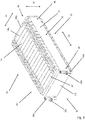
- Fig. 1 shows a voltage supply device 10 which is arranged in a vehicle, not shown.
- the voltage supply device 10 contains a large number of energy supply modules, one of which is identified by way of example with the reference number 12.
- Each of these energy supply modules 12 is constructed from a large number of structurally independently designed energy supply cells, one of which is identified by way of example with reference number 14.
- the energy supply cells 14 can be energy storage cells or energy converter cells. It should preferably be energy storage cells act, which are designed as rechargeable lithium-ion storage cells.
- the energy supply cells are arranged in at least one cell row 16. In the Fig. 1 selected representation, according to which all energy supply modules are designed in one row, should not have any restrictive effect. Of course, the energy supply modules can also be designed in multiple rows. It is also conceivable that single-row and multi-row energy supply modules can be used simultaneously in a voltage supply device.
- Each of the energy supply modules 12 has a tensioning device 18, which is designed to tension the respective energy supply cells 14.
- the bracing device 18 has at least two end plates 20 and a tension element 22. The two end plates 20 and the tension element 22 cooperate to form a bracing force acting on the energy supply cells 14.
- the energy supply modules 12 each interact with a temperature control device 24, which is designed to temperature control at least some of the energy supply cells 14 by means of a heating medium.
- the tension element 22 is designed as a functional component of the temperature control device 24.
- the tension element 22 has at least one feed connection 26 for feeding heat medium into the tension element 22 and at least one discharge connection 28 for discharging the heat medium flowing through at least a partial area of the tension element 22.
- the supply line connection 26 is connected to the temperature control device 24 via a first line 30, wherein heat medium is supplied from the temperature control device 24 to the tension element 22 via the first line 30, which is indicated by an arrow 32.
- the outlet connection 28 is connected to the temperature control device 24 via a second line 34, heat means from the tension element 22 being connected via the second line 34 Temperature control device 24 is supplied, which is indicated by an arrow 36.
- the tension element 22 has at least one in which the heat medium Fig. 1 non-visible heat medium duct.
- Fig. 1 a number of energy supply cells can be found, from which an energy supply module is constructed. This the Fig. 1 removable number should not have a restrictive effect. Of course, an energy supply module can also have a different number of energy supply cells.
- the specific structure of the temperature control device 24 is not to be discussed further within the scope of this invention. It goes without saying that the temperature control device 24 contains those components which are necessary in order to be able to temperature control energy supply cells with the aid of a refrigerant or coolant.
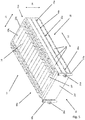
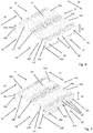
- Fig. 2 shows an energy supply module 12, which is constructed from a plurality of structurally independently designed energy supply cells 14.
- the energy supply cells 14 are arranged in a cell row 16. Points 38 indicate that the energy supply module 12 can be constructed from any number of energy supply cells.
- the energy supply cells 14 are arranged between two end plates 20f, 20q, which interact with a tension element 22 to form a bracing force acting on the energy supply cells 14.
- the tension element 22 is in contact with the energy supply cells 14 via a heat-conducting component 40.
- the heat-conducting component 40 can be designed as a heat-conducting film, as a heat-conducting adhesive or as a so-called phase change material.
- the heat conducting component 40 ensures an optimal heat transfer from the energy supply cells 14 to the tension element 22.
- the tension element 22 is composed of at least one cross element 42 and at least two longitudinal elements 44, each with an end 46 on the cross element side and a free end 48 built up.
- the feed connection 26 and the discharge connection 28 are spatially assigned to the free ends 48.
- the cell row 16 has a cross element-side energy supply cell 14q and a free energy supply cell 14f, one of the two end plates abutting the cross element-side end plate 20q on the cross element side energy supply cell 14q and the other end plate as a free end plate 20f on the free energy supply cell 14f.
- the end plate 14q on the transverse element side is designed to compensate for length tolerances occurring in the cell row 16.
- the energy supply module 12 or the cell row 16 has a longitudinal axis 50 and a transverse axis 52.
- the energy supply cells 14 have a length 54, a width 56 and an in Fig. 2 not shown because height 58 emerges from the plane of the drawing.
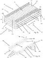
- Fig. 3 shows a first embodiment of an energy supply module 12.
- the energy supply cells 14 are arranged in a single cell row 16, the tension element 22 being constructed from a transverse element 42 and two longitudinal elements 44, each with an end 46 on the transverse element side and a free end 48.
- the cross element 42 and the two longitudinal elements 44 form a tension element 22 which encloses the end plate 20q.
- At least one heat medium channel, which does not carry the heat medium, is incorporated into the tension element.
- the two longitudinal elements 44 rest with their free ends 48 laterally on the end plate 20f.
- the longitudinal elements 44 and the end plate 20f can be connected to one another in a force-locking or material-locking or form-locking manner.
- connection element 60a As shown in Fig. 3 It can be seen that the two longitudinal elements 44 each have a connection element 60a at their free ends 48, one of these two connection elements 60a having the supply connection 26 and the other connection element 60a having the discharge connection 28. This assignment should not have a restrictive effect. In a correspondingly modified manner, the two connections can be located on one of the two connection elements. It is also conceivable that only one longitudinal element has a connection element with both connections. In a corresponding manner, these statements should also apply to the figures to be described below, if this is appropriate.
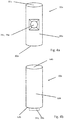
- Fig. 4 consists of two sub-figures 4a and 4b, each showing a cylindrical connection element with a circular base.
- Both connection elements 60a, 60b have a connection element base 62a, 62b, a connection element cover 64a, 64b and a connection element jacket 66a, 66b.
- the feed connection 26a or the discharge connection 28a is arranged in the connection element jacket 66a.
- FIG. 4b shows an alternative type of arrangement, in which the supply connection 26b or the discharge connection 28b is arranged in the connection element base 62b.
- the two connections 26b, 28b can also be arranged in the connection element cover 64b.
- Fig. 5 shows a second embodiment of an energy supply module 12.
- the energy supply cells 14 are arranged in a single row of cells 16.
- the tension element 22a is constructed from a cross element 42a and two longitudinal elements 44a, each with an end 46a on the cross element side and a free end 48a.
- the cross element 42a and the two longitudinal elements 44a form a tension element 22a, which encloses the end plate 20q.
- both the transverse element 42a and the two longitudinal elements 44a are constructed from a multiplicity, in the present case from three structurally independently designed, fluidically parallel or countercurrently connected heat medium channels 68.
- the tension element 22a has a multiplicity of structurally independently designed, fluidically parallel or countercurrently switched heat medium channels 68.
- the two longitudinal elements 44a rest laterally with their free ends 48a on the end plate 20f.
- the longitudinal elements 44a and the end plate 20f can be connected to one another in a force-locking or material-locking or form-locking manner.
- the two longitudinal elements 44a each have a connection element 60a at their free ends 48a, one of these two connection elements having the feed connection 26a and the other connection element 60 having the discharge connection 28a.
- Fig. 6 shows a third embodiment of an energy supply module 12 using two partial figures.
- the basic structure of the energy supply module shown in the two partial figures 6a, 6b corresponds to that in FIG Fig. 3 energy supply module shown, which is why in connection with Fig. 3 made statements should also apply to the energy supply module shown in the sub-figures 6a, 6b.
- the two energy supply modules differ in that the energy supply module 12 shown in the sub-figures 6a, 6b has connection elements 60b, in which the supply connection 26b and the discharge connection 28b are arranged in the connection element base.
- Fig. 7 shows a fourth embodiment of an energy supply module 12 on the basis of two partial figures.
- the basic structure of the energy supply module shown in the two partial figures 7a, 7b corresponds to that in FIG Fig. 5 energy supply module shown, which is why in connection with Fig. 5 made statements should also apply to the energy supply module shown in the sub-figures 7a, 7b.
- the two energy supply modules differ in that the energy supply module 12 shown in the sub-figures 7a, 7b has connection elements 60b in which the supply connection 26b and the discharge connection 28b are arranged in the connection element base.
- the energy supply cells are each arranged in a single row of cells.
- the energy supply cells are arranged in a plurality, specifically in two, one row of cells arranged next to one another.
- the tension element for the energy supply modules shown in the aforementioned figures is constructed from a transverse element and two longitudinal elements, each with a transverse element end and a free end, the transverse element and the two Longitudinal elements form a tension element which encloses at least one end plate.
- Fig. 8 shows a fifth embodiment of an energy supply module 12.
- the energy supply cells 14 are arranged in two cell rows 16, the tension element 22 'being constructed from a transverse element 42' and two longitudinal elements 44 ', each with a transverse element end 46 and a free end 48.
- the transverse element 42 'and the two longitudinal elements 44' form a tension element 22 'which the End plate 20q 'encloses.
- At least one heat medium channel, which does not carry the heat medium, is incorporated into the tension element 22 '.
- the free ends 48 of the two longitudinal elements 44 ' lie laterally on the end plate 20f'.
- the longitudinal elements 44 'and the end plate 20f can be connected to one another in a force-locking or material-locking or form-locking manner.
- a heat conducting plate 70 is arranged between the two cell rows 16, with which it is possible to supply heat to the two end plates 20f ', 20q' from those sides of the energy supply cells which face the space between the two cell rows 16.
- connection element 60a As shown in Fig. 8 As can be seen, the two longitudinal elements 44 'each have a connection element 60a at their free ends 48, one of these two connection elements 60a having the feed connection 26a and the other connection element 60a having the discharge connection 28a. Correspondingly, those related to Fig. 3 statements made apply.
- Fig. 9 shows a sixth embodiment of an energy supply module 12.
- the energy supply cells 14 are arranged in two cell rows 16.
- the tension element 22a ' is constructed from a cross element 42a' and two longitudinal elements 44a ', each with an end 46a on the cross element side and a free end 48a.
- the cross element 42a 'and the two longitudinal elements 44a' form a tension element 22a 'which encloses the end plate 20q'.
- both the transverse element 42a 'and the two longitudinal elements 44a' are constructed from a multiplicity, in the present case from three structurally independently constructed, fluidically parallel or countercurrently connected heat medium channels 68 '.
- the tension element 22a ' has a plurality of structurally independently designed, fluidically parallel or countercurrently switched heat medium channels 68'.
- the two longitudinal elements 44a ' lie with their free ends 48a on the side of the end plate 20f '.
- the longitudinal elements 44a 'and the end plate 20f' can be connected to one another in a force-locking or material-locking or form-locking manner.
- the two longitudinal elements 44a 'each have a connection element 60a at their free ends 48a, one of these two connection elements 60a having the supply connection 26a and the other connection element 60a having the discharge connection 28a.
- a heat conducting plate 70 is arranged between the two rows of cells 16.
- the free end plate 20f ' is designed such that it abuts two free energy supply cells 14f
- the cross member-side end plate 20q' is designed such that it abuts two cross member-side energy 14q.
- the heat-conducting plate 70 should be a component that is passively designed with regard to heat transfer. Alternatively, the use of an actively trained component is conceivable.
- the energy supply cells 14 are also arranged in a plurality, specifically in two, one row of cells 16 arranged in one plane.
- the tension element 22 is formed meandering in these two embodiments.
- the energy supply module 12 is the tension element 22 "from two transverse elements 42", two longitudinal elements 44 ", each with a transverse element end 46 and a free end 48 and (due to the perspective view difficult to see) further longitudinal element 72 with two Ends constructed on the transverse element side (due to the perspective representation that is difficult to see.)
- the further longitudinal element 72 can also be designed for this purpose, likewise from the heating means to be flowed through, ie it can be a component that is actively designed with regard to heat transfer. Alternatively, it is also conceivable to design the further longitudinal element passively.
- Fig. 11 is shown an energy supply module constructed according to an eighth embodiment, the basic structure of which in Fig. 10 shown energy supply module corresponds, which is why in connection with Fig. 10 made also for the in Fig. 11 shown energy supply module should apply.
- the two energy supply modules differ in that the in Fig. 11 energy supply module 12 shown, both the transverse elements 42a "and the two longitudinal elements 44a" are constructed from a large number, in the present case from three structurally independently designed, fluidically parallel or countercurrently switched heat medium channels 68 ".
- the traction element 22a" has a large number of structurally independently designed ones , fluidically parallel or counterflow switched heat medium channels 68 ".
- connection elements 60a are used in the energy supply modules shown in these figures, in which both the supply connection 26a and the discharge connection 28a are arranged in the connection element jacket, should not have any restrictive effect.
- connection elements can also be used in which these connections are arranged in the connection element base and / or in the connection element cover.
Applications Claiming Priority (2)
| Application Number | Priority Date | Filing Date | Title |
|---|---|---|---|
| DE102014218330.8A DE102014218330A1 (de) | 2014-09-12 | 2014-09-12 | Energiebereitstellungsmodul für eine in einem Fahrzeug angeordnete Spannungsversorgungsvorrichtung |
| PCT/EP2015/062324 WO2016037714A1 (de) | 2014-09-12 | 2015-06-03 | Energiebereitstellungsmodul für eine in einem fahrzeug angeordnete spannungsversorgungsvorrichtung |
Publications (2)
| Publication Number | Publication Date |
|---|---|
| EP3192109A1 EP3192109A1 (de) | 2017-07-19 |
| EP3192109B1 true EP3192109B1 (de) | 2020-01-08 |
Family
ID=53298362
Family Applications (1)
| Application Number | Title | Priority Date | Filing Date |
|---|---|---|---|
| EP15727382.2A Active EP3192109B1 (de) | 2014-09-12 | 2015-06-03 | Energiebereitstellungsmodul für eine in einem fahrzeug angeordnete spannungsversorgungsvorrichtung |
Country Status (6)
| Country | Link |
|---|---|
| US (1) | US20170194680A1 (zh) |
| EP (1) | EP3192109B1 (zh) |
| JP (1) | JP6655062B2 (zh) |
| CN (1) | CN106463762B (zh) |
| DE (1) | DE102014218330A1 (zh) |
| WO (1) | WO2016037714A1 (zh) |
Families Citing this family (17)
| Publication number | Priority date | Publication date | Assignee | Title |
|---|---|---|---|---|
| US11135910B2 (en) * | 2017-06-25 | 2021-10-05 | Brp-Rotax Gmbh & Co. Kg | Electric kart and battery |
| CN110959224A (zh) * | 2017-07-31 | 2020-04-03 | 松下知识产权经营株式会社 | 电池模块、电池组以及合并电池组 |
| KR102159347B1 (ko) * | 2017-11-14 | 2020-09-23 | 주식회사 엘지화학 | 배터리 셀 가압형 엔드 플레이트와 확장형 센싱 하우징 구조가 적용된 배터리 모듈 |
| DE102017222771A1 (de) | 2017-12-14 | 2019-06-19 | Bayerische Motoren Werke Aktiengesellschaft | Speichereinrichtung zum Speichern von elektrischer Energie für ein Kraftfahrzeug |
| KR102150679B1 (ko) * | 2018-03-13 | 2020-09-01 | 주식회사 엘지화학 | 배터리 모듈, 이러한 배터리 모듈을 포함하는 배터리 팩 및 이러한 배터리 팩을 포함하는 자동차 |
| US10631429B2 (en) * | 2018-07-13 | 2020-04-21 | Ford Global Technologies, Llc | Vehicle power module assembly |
| DE102018213153A1 (de) | 2018-08-07 | 2020-02-13 | Audi Ag | Befeuchter, Brennstoffzellenvorrichtung mit Befeuchter sowie Kraftfahrzeug |
| DE102019208003A1 (de) * | 2019-05-31 | 2020-12-03 | Robert Bosch Gmbh | Batteriemodul |
| DE102019118392A1 (de) * | 2019-07-08 | 2020-05-28 | Bayerische Motoren Werke Aktiengesellschaft | Batterie für ein Kraftfahrzeug und Kraftfahrzeug |
| DE102019121964B4 (de) * | 2019-08-15 | 2024-03-21 | Dr. Ing. H.C. F. Porsche Aktiengesellschaft | Verfahren zur Herstellung eines Batteriemoduls einer Kraftfahrzeugbatterie,Batteriemodul sowie Kraftfahrzeug |
| DE102019215636A1 (de) * | 2019-10-11 | 2021-04-15 | Robert Bosch Gmbh | Batteriemodul |
| CN111049221B (zh) * | 2019-12-26 | 2022-01-07 | 湖南绿色再生资源有限公司 | 锂离子电池放电装置及其控制方法、控制器 |
| DE102020201139A1 (de) | 2020-01-30 | 2021-08-05 | Robert Bosch Gesellschaft mit beschränkter Haftung | Batterie |
| CN111430837B (zh) * | 2020-03-16 | 2021-08-03 | 深圳航美新材料科技有限公司 | 一种锂电池半成品的热管理方法、锂电池的制作方法 |
| EP4109630B1 (en) * | 2021-06-22 | 2023-12-06 | Volvo Car Corporation | Cooling system for a battery module |
| DE102021207410A1 (de) | 2021-07-13 | 2023-01-19 | Robert Bosch Gesellschaft mit beschränkter Haftung | Verfahren zur Herstellung eines Batteriemoduls und Batteriemodul |
| FR3131098A1 (fr) * | 2021-12-20 | 2023-06-23 | Saft | Module électrochimique, procédé de fabrication et Assemblage électrochimique correspondants |
Family Cites Families (12)
| Publication number | Priority date | Publication date | Assignee | Title |
|---|---|---|---|---|
| JP4839955B2 (ja) * | 2006-05-11 | 2011-12-21 | トヨタ自動車株式会社 | 電池パックおよび車両 |
| KR101361375B1 (ko) * | 2009-12-07 | 2014-02-11 | 스미도모쥬기가이고교 가부시키가이샤 | 쇼벨 |
| US8383260B2 (en) * | 2010-02-26 | 2013-02-26 | GM Global Technology Operations LLC | U-formed cooling plate with solid fins for lithium pouch cells |
| KR101108191B1 (ko) * | 2010-05-24 | 2012-02-06 | 에스비리모티브 주식회사 | 배터리 팩 |
| JP5484301B2 (ja) * | 2010-12-08 | 2014-05-07 | 住友重機械工業株式会社 | 蓄電モジュール及び作業機械 |
| DE102011013618A1 (de) * | 2011-03-11 | 2012-09-13 | Li-Tec Battery Gmbh | Energiespeichervorrichtung |
| DE102011015152A1 (de) * | 2011-03-25 | 2012-09-27 | Li-Tec Battery Gmbh | Energiespeichervorrichtung, Energiespeicherzelle und Wärmeleitelement mit elastischem Mittel |
| DE102011076580A1 (de) * | 2011-05-27 | 2012-11-29 | Bayerische Motoren Werke Aktiengesellschaft | Energiespeichermodul aus mehreren prismatischen Speicherzellen |
| DE102011120511A1 (de) * | 2011-12-07 | 2013-06-13 | Daimler Ag | Batterie und Zellblock für eine Batterie |
| CA2860465C (en) * | 2012-01-05 | 2020-07-14 | Electrovaya Inc. | Fluid-cooled battery module containing battery cells |
| DE102012221503B4 (de) * | 2012-11-23 | 2022-01-05 | Vitesco Technologies GmbH | Energiespeicher mit einer Vielzahl von Energiespeicherzellen und mit einem Gehäuse sowie Verfahren zum Herstellen eines Energiespeichers |
| DE102013201096A1 (de) * | 2013-01-24 | 2014-07-24 | Robert Bosch Gmbh | Batteriesystem mit Batteriezellen und einer Vorrichtung zur Temperierung der Batteriezellen |
-
2014
- 2014-09-12 DE DE102014218330.8A patent/DE102014218330A1/de not_active Withdrawn
-
2015
- 2015-06-03 CN CN201580030781.1A patent/CN106463762B/zh active Active
- 2015-06-03 EP EP15727382.2A patent/EP3192109B1/de active Active
- 2015-06-03 JP JP2017506277A patent/JP6655062B2/ja active Active
- 2015-06-03 WO PCT/EP2015/062324 patent/WO2016037714A1/de active Application Filing
-
2017
- 2017-03-10 US US15/455,396 patent/US20170194680A1/en not_active Abandoned
Non-Patent Citations (1)
| Title |
|---|
| None * |
Also Published As
| Publication number | Publication date |
|---|---|
| CN106463762A (zh) | 2017-02-22 |
| JP2017535022A (ja) | 2017-11-24 |
| WO2016037714A1 (de) | 2016-03-17 |
| DE102014218330A1 (de) | 2016-03-17 |
| JP6655062B2 (ja) | 2020-02-26 |
| CN106463762B (zh) | 2019-04-09 |
| EP3192109A1 (de) | 2017-07-19 |
| US20170194680A1 (en) | 2017-07-06 |
Similar Documents
| Publication | Publication Date | Title |
|---|---|---|
| EP3192109B1 (de) | Energiebereitstellungsmodul für eine in einem fahrzeug angeordnete spannungsversorgungsvorrichtung | |
| EP2599153B1 (de) | Vorrichtung zur spannungsversorgung mit einer kühlanordnung | |
| DE102012222732B4 (de) | Batteriezellenmodul | |
| EP2789029B1 (de) | Batterie und zellblock für eine batterie | |
| EP1271085B1 (de) | Vorrichtung zum Kühlen einer Fahrzeugeinrichtung, insbesondere Batterie oder Brennstoffzelle | |
| WO2018024483A1 (de) | Temperiereinrichtung für ein batteriegehäuse eines fahrzeuges | |
| WO2007076985A2 (de) | Wärmetauscher mit tiefgezogenen wärmetauscher-platten | |
| DE102011100623A1 (de) | Fahrzeug mit einer Batterie | |
| WO2012028298A2 (de) | Kühlmodul und verfahren zum herstellen eines kühlmoduls | |
| DE102012111970A1 (de) | Batterieanordnung und Verfahren zum Kühlen einer Batterie | |
| WO2016045855A1 (de) | Ausgleichsvorrichtung und akkumulatormodul mit derselben | |
| EP2780958B1 (de) | Batteriesystem mit einem temperierkörper enthaltend einen temperierkanal und einen bypass sowie kraftfahrzeug welches das batteriesystem enthält | |
| DE102010051106B4 (de) | Vorrichtung zum Kühlen eines Energiespeichermoduls eines Fahrzeugs | |
| WO2021233778A1 (de) | Energiespeichervorrichtung mit einem batterie-zellenmodul und einer kühlvorrichtung, vorzugsweise für ein zumindest teilweise elektrisch angetriebenes fahrzeug, und verfahren zur herstellung der energiespeichervorrichtung | |
| DE102014106949A1 (de) | Antriebsbatteriebaugruppe | |
| DE102017116984B4 (de) | Temperiervorrichtung für eine Temperierung eines Batteriesystems sowie Batteriesystem | |
| EP3557654A1 (de) | Montageanordnung eines elektrisch antreibbaren kraftfahrzeugs | |
| DE102017208754A1 (de) | Batteriesystem für ein Elektrofahrzeug | |
| DE102017201015A1 (de) | Batterieeinrichtung | |
| DE102012108767B4 (de) | Batteriemodul | |
| WO2012100914A1 (de) | Energiespeichermodul für eine vorrichtung zur spannungsversorgung und verfahren zum herstellen eines solchen energiespeichermoduls | |
| DE102011100624B4 (de) | Fahrzeug mit einer Batterie | |
| DE102012207995B4 (de) | Kühleinrichtung sowie Energiespeicher mit einer Kühleinrichtung | |
| EP3350852B1 (de) | Gehäuseanordnung für zumindest eine batteriezelle | |
| DE102019210197A1 (de) | Energiespeicherzellenstapel |
Legal Events
| Date | Code | Title | Description |
|---|---|---|---|
| STAA | Information on the status of an ep patent application or granted ep patent |
Free format text: STATUS: THE INTERNATIONAL PUBLICATION HAS BEEN MADE |
|
| PUAI | Public reference made under article 153(3) epc to a published international application that has entered the european phase |
Free format text: ORIGINAL CODE: 0009012 |
|
| STAA | Information on the status of an ep patent application or granted ep patent |
Free format text: STATUS: REQUEST FOR EXAMINATION WAS MADE |
|
| 17P | Request for examination filed |
Effective date: 20170227 |
|
| AK | Designated contracting states |
Kind code of ref document: A1 Designated state(s): AL AT BE BG CH CY CZ DE DK EE ES FI FR GB GR HR HU IE IS IT LI LT LU LV MC MK MT NL NO PL PT RO RS SE SI SK SM TR |
|
| AX | Request for extension of the european patent |
Extension state: BA ME |
|
| DAV | Request for validation of the european patent (deleted) | ||
| DAX | Request for extension of the european patent (deleted) | ||
| STAA | Information on the status of an ep patent application or granted ep patent |
Free format text: STATUS: EXAMINATION IS IN PROGRESS |
|
| 17Q | First examination report despatched |
Effective date: 20180409 |
|
| GRAP | Despatch of communication of intention to grant a patent |
Free format text: ORIGINAL CODE: EPIDOSNIGR1 |
|
| STAA | Information on the status of an ep patent application or granted ep patent |
Free format text: STATUS: GRANT OF PATENT IS INTENDED |
|
| RIC1 | Information provided on ipc code assigned before grant |
Ipc: H01M 10/625 20140101ALI20190724BHEP Ipc: H01M 10/647 20140101ALI20190724BHEP Ipc: H01M 10/04 20060101ALI20190724BHEP Ipc: H01M 10/6556 20140101ALI20190724BHEP Ipc: H01M 2/10 20060101AFI20190724BHEP |
|
| INTG | Intention to grant announced |
Effective date: 20190823 |
|
| GRAS | Grant fee paid |
Free format text: ORIGINAL CODE: EPIDOSNIGR3 |
|
| GRAA | (expected) grant |
Free format text: ORIGINAL CODE: 0009210 |
|
| STAA | Information on the status of an ep patent application or granted ep patent |
Free format text: STATUS: THE PATENT HAS BEEN GRANTED |
|
| AK | Designated contracting states |
Kind code of ref document: B1 Designated state(s): AL AT BE BG CH CY CZ DE DK EE ES FI FR GB GR HR HU IE IS IT LI LT LU LV MC MK MT NL NO PL PT RO RS SE SI SK SM TR |
|
| REG | Reference to a national code |
Ref country code: GB Ref legal event code: FG4D Free format text: NOT ENGLISH |
|
| REG | Reference to a national code |
Ref country code: CH Ref legal event code: EP |
|
| REG | Reference to a national code |
Ref country code: DE Ref legal event code: R096 Ref document number: 502015011467 Country of ref document: DE |
|
| REG | Reference to a national code |
Ref country code: IE Ref legal event code: FG4D Free format text: LANGUAGE OF EP DOCUMENT: GERMAN |
|
| REG | Reference to a national code |
Ref country code: AT Ref legal event code: REF Ref document number: 1223805 Country of ref document: AT Kind code of ref document: T Effective date: 20200215 |
|
| REG | Reference to a national code |
Ref country code: NL Ref legal event code: MP Effective date: 20200108 |
|
| REG | Reference to a national code |
Ref country code: LT Ref legal event code: MG4D |
|
| PG25 | Lapsed in a contracting state [announced via postgrant information from national office to epo] |
Ref country code: FI Free format text: LAPSE BECAUSE OF FAILURE TO SUBMIT A TRANSLATION OF THE DESCRIPTION OR TO PAY THE FEE WITHIN THE PRESCRIBED TIME-LIMIT Effective date: 20200108 Ref country code: NO Free format text: LAPSE BECAUSE OF FAILURE TO SUBMIT A TRANSLATION OF THE DESCRIPTION OR TO PAY THE FEE WITHIN THE PRESCRIBED TIME-LIMIT Effective date: 20200408 Ref country code: NL Free format text: LAPSE BECAUSE OF FAILURE TO SUBMIT A TRANSLATION OF THE DESCRIPTION OR TO PAY THE FEE WITHIN THE PRESCRIBED TIME-LIMIT Effective date: 20200108 Ref country code: LT Free format text: LAPSE BECAUSE OF FAILURE TO SUBMIT A TRANSLATION OF THE DESCRIPTION OR TO PAY THE FEE WITHIN THE PRESCRIBED TIME-LIMIT Effective date: 20200108 Ref country code: PT Free format text: LAPSE BECAUSE OF FAILURE TO SUBMIT A TRANSLATION OF THE DESCRIPTION OR TO PAY THE FEE WITHIN THE PRESCRIBED TIME-LIMIT Effective date: 20200531 Ref country code: RS Free format text: LAPSE BECAUSE OF FAILURE TO SUBMIT A TRANSLATION OF THE DESCRIPTION OR TO PAY THE FEE WITHIN THE PRESCRIBED TIME-LIMIT Effective date: 20200108 |
|
| PG25 | Lapsed in a contracting state [announced via postgrant information from national office to epo] |
Ref country code: BG Free format text: LAPSE BECAUSE OF FAILURE TO SUBMIT A TRANSLATION OF THE DESCRIPTION OR TO PAY THE FEE WITHIN THE PRESCRIBED TIME-LIMIT Effective date: 20200408 Ref country code: HR Free format text: LAPSE BECAUSE OF FAILURE TO SUBMIT A TRANSLATION OF THE DESCRIPTION OR TO PAY THE FEE WITHIN THE PRESCRIBED TIME-LIMIT Effective date: 20200108 Ref country code: GR Free format text: LAPSE BECAUSE OF FAILURE TO SUBMIT A TRANSLATION OF THE DESCRIPTION OR TO PAY THE FEE WITHIN THE PRESCRIBED TIME-LIMIT Effective date: 20200409 Ref country code: SE Free format text: LAPSE BECAUSE OF FAILURE TO SUBMIT A TRANSLATION OF THE DESCRIPTION OR TO PAY THE FEE WITHIN THE PRESCRIBED TIME-LIMIT Effective date: 20200108 Ref country code: IS Free format text: LAPSE BECAUSE OF FAILURE TO SUBMIT A TRANSLATION OF THE DESCRIPTION OR TO PAY THE FEE WITHIN THE PRESCRIBED TIME-LIMIT Effective date: 20200508 Ref country code: LV Free format text: LAPSE BECAUSE OF FAILURE TO SUBMIT A TRANSLATION OF THE DESCRIPTION OR TO PAY THE FEE WITHIN THE PRESCRIBED TIME-LIMIT Effective date: 20200108 |
|
| REG | Reference to a national code |
Ref country code: DE Ref legal event code: R097 Ref document number: 502015011467 Country of ref document: DE |
|
| PG25 | Lapsed in a contracting state [announced via postgrant information from national office to epo] |
Ref country code: ES Free format text: LAPSE BECAUSE OF FAILURE TO SUBMIT A TRANSLATION OF THE DESCRIPTION OR TO PAY THE FEE WITHIN THE PRESCRIBED TIME-LIMIT Effective date: 20200108 Ref country code: CZ Free format text: LAPSE BECAUSE OF FAILURE TO SUBMIT A TRANSLATION OF THE DESCRIPTION OR TO PAY THE FEE WITHIN THE PRESCRIBED TIME-LIMIT Effective date: 20200108 Ref country code: SK Free format text: LAPSE BECAUSE OF FAILURE TO SUBMIT A TRANSLATION OF THE DESCRIPTION OR TO PAY THE FEE WITHIN THE PRESCRIBED TIME-LIMIT Effective date: 20200108 Ref country code: RO Free format text: LAPSE BECAUSE OF FAILURE TO SUBMIT A TRANSLATION OF THE DESCRIPTION OR TO PAY THE FEE WITHIN THE PRESCRIBED TIME-LIMIT Effective date: 20200108 Ref country code: EE Free format text: LAPSE BECAUSE OF FAILURE TO SUBMIT A TRANSLATION OF THE DESCRIPTION OR TO PAY THE FEE WITHIN THE PRESCRIBED TIME-LIMIT Effective date: 20200108 Ref country code: SM Free format text: LAPSE BECAUSE OF FAILURE TO SUBMIT A TRANSLATION OF THE DESCRIPTION OR TO PAY THE FEE WITHIN THE PRESCRIBED TIME-LIMIT Effective date: 20200108 Ref country code: DK Free format text: LAPSE BECAUSE OF FAILURE TO SUBMIT A TRANSLATION OF THE DESCRIPTION OR TO PAY THE FEE WITHIN THE PRESCRIBED TIME-LIMIT Effective date: 20200108 |
|
| PLBE | No opposition filed within time limit |
Free format text: ORIGINAL CODE: 0009261 |
|
| STAA | Information on the status of an ep patent application or granted ep patent |
Free format text: STATUS: NO OPPOSITION FILED WITHIN TIME LIMIT |
|
| REG | Reference to a national code |
Ref country code: DE Ref legal event code: R079 Ref document number: 502015011467 Country of ref document: DE Free format text: PREVIOUS MAIN CLASS: H01M0002100000 Ipc: H01M0050200000 |
|
| 26N | No opposition filed |
Effective date: 20201009 |
|
| PG25 | Lapsed in a contracting state [announced via postgrant information from national office to epo] |
Ref country code: MC Free format text: LAPSE BECAUSE OF FAILURE TO SUBMIT A TRANSLATION OF THE DESCRIPTION OR TO PAY THE FEE WITHIN THE PRESCRIBED TIME-LIMIT Effective date: 20200108 |
|
| REG | Reference to a national code |
Ref country code: CH Ref legal event code: PL |
|
| PG25 | Lapsed in a contracting state [announced via postgrant information from national office to epo] |
Ref country code: PL Free format text: LAPSE BECAUSE OF FAILURE TO SUBMIT A TRANSLATION OF THE DESCRIPTION OR TO PAY THE FEE WITHIN THE PRESCRIBED TIME-LIMIT Effective date: 20200108 Ref country code: SI Free format text: LAPSE BECAUSE OF FAILURE TO SUBMIT A TRANSLATION OF THE DESCRIPTION OR TO PAY THE FEE WITHIN THE PRESCRIBED TIME-LIMIT Effective date: 20200108 |
|
| PG25 | Lapsed in a contracting state [announced via postgrant information from national office to epo] |
Ref country code: LU Free format text: LAPSE BECAUSE OF NON-PAYMENT OF DUE FEES Effective date: 20200603 |
|
| REG | Reference to a national code |
Ref country code: BE Ref legal event code: MM Effective date: 20200630 |
|
| PG25 | Lapsed in a contracting state [announced via postgrant information from national office to epo] |
Ref country code: LI Free format text: LAPSE BECAUSE OF NON-PAYMENT OF DUE FEES Effective date: 20200630 Ref country code: CH Free format text: LAPSE BECAUSE OF NON-PAYMENT OF DUE FEES Effective date: 20200630 Ref country code: IE Free format text: LAPSE BECAUSE OF NON-PAYMENT OF DUE FEES Effective date: 20200603 |
|
| PG25 | Lapsed in a contracting state [announced via postgrant information from national office to epo] |
Ref country code: BE Free format text: LAPSE BECAUSE OF NON-PAYMENT OF DUE FEES Effective date: 20200630 |
|
| REG | Reference to a national code |
Ref country code: AT Ref legal event code: MM01 Ref document number: 1223805 Country of ref document: AT Kind code of ref document: T Effective date: 20200603 |
|
| PG25 | Lapsed in a contracting state [announced via postgrant information from national office to epo] |
Ref country code: AT Free format text: LAPSE BECAUSE OF NON-PAYMENT OF DUE FEES Effective date: 20200603 |
|
| PG25 | Lapsed in a contracting state [announced via postgrant information from national office to epo] |
Ref country code: TR Free format text: LAPSE BECAUSE OF FAILURE TO SUBMIT A TRANSLATION OF THE DESCRIPTION OR TO PAY THE FEE WITHIN THE PRESCRIBED TIME-LIMIT Effective date: 20200108 Ref country code: MT Free format text: LAPSE BECAUSE OF FAILURE TO SUBMIT A TRANSLATION OF THE DESCRIPTION OR TO PAY THE FEE WITHIN THE PRESCRIBED TIME-LIMIT Effective date: 20200108 Ref country code: CY Free format text: LAPSE BECAUSE OF FAILURE TO SUBMIT A TRANSLATION OF THE DESCRIPTION OR TO PAY THE FEE WITHIN THE PRESCRIBED TIME-LIMIT Effective date: 20200108 |
|
| PG25 | Lapsed in a contracting state [announced via postgrant information from national office to epo] |
Ref country code: MK Free format text: LAPSE BECAUSE OF FAILURE TO SUBMIT A TRANSLATION OF THE DESCRIPTION OR TO PAY THE FEE WITHIN THE PRESCRIBED TIME-LIMIT Effective date: 20200108 Ref country code: AL Free format text: LAPSE BECAUSE OF FAILURE TO SUBMIT A TRANSLATION OF THE DESCRIPTION OR TO PAY THE FEE WITHIN THE PRESCRIBED TIME-LIMIT Effective date: 20200108 |
|
| P01 | Opt-out of the competence of the unified patent court (upc) registered |
Effective date: 20230502 |
|
| PGFP | Annual fee paid to national office [announced via postgrant information from national office to epo] |
Ref country code: FR Payment date: 20230620 Year of fee payment: 9 Ref country code: DE Payment date: 20230620 Year of fee payment: 9 |
|
| PGFP | Annual fee paid to national office [announced via postgrant information from national office to epo] |
Ref country code: IT Payment date: 20230630 Year of fee payment: 9 Ref country code: GB Payment date: 20230622 Year of fee payment: 9 |