EP3192004B1 - Reading device and bar code machine including such device for automatic analysis of a sample - Google Patents
Reading device and bar code machine including such device for automatic analysis of a sample Download PDFInfo
- Publication number
- EP3192004B1 EP3192004B1 EP15778988.4A EP15778988A EP3192004B1 EP 3192004 B1 EP3192004 B1 EP 3192004B1 EP 15778988 A EP15778988 A EP 15778988A EP 3192004 B1 EP3192004 B1 EP 3192004B1
- Authority
- EP
- European Patent Office
- Prior art keywords
- barcode
- optical system
- auxiliary optical
- auxiliary
- light
- Prior art date
- Legal status (The legal status is an assumption and is not a legal conclusion. Google has not performed a legal analysis and makes no representation as to the accuracy of the status listed.)
- Active
Links
- 230000003287 optical effect Effects 0.000 claims description 133
- 230000003750 conditioning effect Effects 0.000 claims description 42
- 238000011084 recovery Methods 0.000 claims description 22
- 241001644893 Entandrophragma utile Species 0.000 description 27
- 239000000523 sample Substances 0.000 description 6
- 241001080024 Telles Species 0.000 description 4
- 230000006870 function Effects 0.000 description 4
- 239000003153 chemical reaction reagent Substances 0.000 description 2
- 238000001914 filtration Methods 0.000 description 2
- 238000002360 preparation method Methods 0.000 description 2
- 240000008042 Zea mays Species 0.000 description 1
- 230000000712 assembly Effects 0.000 description 1
- 238000000429 assembly Methods 0.000 description 1
- 239000012472 biological sample Substances 0.000 description 1
- 230000005540 biological transmission Effects 0.000 description 1
- 239000003085 diluting agent Substances 0.000 description 1
- 238000010790 dilution Methods 0.000 description 1
- 239000012895 dilution Substances 0.000 description 1
- 238000005286 illumination Methods 0.000 description 1
- 238000000034 method Methods 0.000 description 1
- 238000012986 modification Methods 0.000 description 1
- 230000004048 modification Effects 0.000 description 1
- 238000004806 packaging method and process Methods 0.000 description 1
- 239000007787 solid Substances 0.000 description 1
- 230000001131 transforming effect Effects 0.000 description 1
Images


Classifications
-
- G—PHYSICS
- G06—COMPUTING; CALCULATING OR COUNTING
- G06K—GRAPHICAL DATA READING; PRESENTATION OF DATA; RECORD CARRIERS; HANDLING RECORD CARRIERS
- G06K7/00—Methods or arrangements for sensing record carriers, e.g. for reading patterns
- G06K7/10—Methods or arrangements for sensing record carriers, e.g. for reading patterns by electromagnetic radiation, e.g. optical sensing; by corpuscular radiation
- G06K7/10544—Methods or arrangements for sensing record carriers, e.g. for reading patterns by electromagnetic radiation, e.g. optical sensing; by corpuscular radiation by scanning of the records by radiation in the optical part of the electromagnetic spectrum
- G06K7/10792—Special measures in relation to the object to be scanned
- G06K7/10801—Multidistance reading
- G06K7/10811—Focalisation
-
- G—PHYSICS
- G06—COMPUTING; CALCULATING OR COUNTING
- G06K—GRAPHICAL DATA READING; PRESENTATION OF DATA; RECORD CARRIERS; HANDLING RECORD CARRIERS
- G06K7/00—Methods or arrangements for sensing record carriers, e.g. for reading patterns
- G06K7/10—Methods or arrangements for sensing record carriers, e.g. for reading patterns by electromagnetic radiation, e.g. optical sensing; by corpuscular radiation
- G06K7/14—Methods or arrangements for sensing record carriers, e.g. for reading patterns by electromagnetic radiation, e.g. optical sensing; by corpuscular radiation using light without selection of wavelength, e.g. sensing reflected white light
- G06K7/1404—Methods for optical code recognition
- G06K7/1408—Methods for optical code recognition the method being specifically adapted for the type of code
- G06K7/1413—1D bar codes
-
- G—PHYSICS
- G06—COMPUTING; CALCULATING OR COUNTING
- G06K—GRAPHICAL DATA READING; PRESENTATION OF DATA; RECORD CARRIERS; HANDLING RECORD CARRIERS
- G06K7/00—Methods or arrangements for sensing record carriers, e.g. for reading patterns
- G06K7/10—Methods or arrangements for sensing record carriers, e.g. for reading patterns by electromagnetic radiation, e.g. optical sensing; by corpuscular radiation
- G06K7/10544—Methods or arrangements for sensing record carriers, e.g. for reading patterns by electromagnetic radiation, e.g. optical sensing; by corpuscular radiation by scanning of the records by radiation in the optical part of the electromagnetic spectrum
- G06K7/10554—Moving beam scanning
- G06K7/10564—Light sources
-
- G—PHYSICS
- G06—COMPUTING; CALCULATING OR COUNTING
- G06K—GRAPHICAL DATA READING; PRESENTATION OF DATA; RECORD CARRIERS; HANDLING RECORD CARRIERS
- G06K7/00—Methods or arrangements for sensing record carriers, e.g. for reading patterns
- G06K7/10—Methods or arrangements for sensing record carriers, e.g. for reading patterns by electromagnetic radiation, e.g. optical sensing; by corpuscular radiation
- G06K7/10544—Methods or arrangements for sensing record carriers, e.g. for reading patterns by electromagnetic radiation, e.g. optical sensing; by corpuscular radiation by scanning of the records by radiation in the optical part of the electromagnetic spectrum
- G06K7/10821—Methods or arrangements for sensing record carriers, e.g. for reading patterns by electromagnetic radiation, e.g. optical sensing; by corpuscular radiation by scanning of the records by radiation in the optical part of the electromagnetic spectrum further details of bar or optical code scanning devices
- G06K7/10831—Arrangement of optical elements, e.g. lenses, mirrors, prisms
-
- G—PHYSICS
- G06—COMPUTING; CALCULATING OR COUNTING
- G06K—GRAPHICAL DATA READING; PRESENTATION OF DATA; RECORD CARRIERS; HANDLING RECORD CARRIERS
- G06K7/00—Methods or arrangements for sensing record carriers, e.g. for reading patterns
- G06K7/10—Methods or arrangements for sensing record carriers, e.g. for reading patterns by electromagnetic radiation, e.g. optical sensing; by corpuscular radiation
- G06K2007/10485—Arrangement of optical elements
Description
L'invention concerne un dispositif de lecture de code-barres ainsi qu'une machine pour l'analyse automatisé d'un échantillon comprenant un tel dispositif.The invention relates to a barcode reading device and a machine for automated analysis of a sample comprising such a device.
Les systèmes de codes-barres sont utilisés dans de très nombreuses applications pour coder des informations dans un format aisément lisible par des dispositifs optiques de lecture automatisée. Un code-barres en soi est une représentation graphique qui, dans sa variante la plus courante, est constituée d'une série de barres agencées côte à côte. Les barres peuvent présenter une épaisseur différente et sont espacées l'une de l'autre par des intervalles. Les barres sont généralement noires ou sombres, tandis que les intervalles entre les barres sont dans une couleur contrastée par rapport au noir, c'est-à-dire une couleur claire, généralement blanche. De tels codes-barres sont définis par exemple par les systèmes appelés « EAN 8 », « EAN 13 », « code 39 », « code 128 », « POSTNET » etc. On notera qu'il existe aussi des systèmes appartenant à la famille des codes-barres qui, à proprement parler ne présentent pas des barres, mais présentent des modules noirs disposés dans un carré à fond blanc par exemple. De tels systèmes sont aussi appelés codes-barres en deux dimensions ou bidimensionnels et sont connus par ailleurs sous les dénominations commerciales « code QR », « Flashcode », ou « DataMatrix ». Dans tous les cas, il existe des algorithmes qui permettent de coder des informations de type numérique ou alphanumérique en des informations sous forme de codes-barres à une dimension ou à deux dimensions.Barcode systems are used in a wide variety of applications to encode information in a format easily readable by automated reading optical devices. A bar code per se is a graphic representation which, in its most common variant, consists of a series of bars arranged side by side. The bars may have a different thickness and are spaced from one another by intervals. The bars are usually black or dark, while the intervals between the bars are in a contrasting color compared to black, ie a light color, usually white. Such barcodes are defined for example by the systems called "EAN 8", "EAN 13", "code 39", "code 128", "POSTNET" etc. It will be noted that there are also systems belonging to the family of barcodes which, strictly speaking, do not have bars but have black modules arranged in a square with a white background for example. Such systems are also known as two-dimensional or two-dimensional barcodes and are otherwise known by the trade names "QR code", "Flashcode", or "DataMatrix". In any case, there are algorithms that can encode numeric or alphanumeric information into one-dimensional or two-dimensional barcode information.
Ainsi, une information donnée est codée sous la forme d'une image, le code-barres, qui peut être apposé de manière virtuelle ou réelle sur des documents, des objets, voire même sur des êtres vivants, de manière à associer l'information codée au document, à l'objet, à l'être vivant portant le code-barres. Dans de très nombreux cas, le code-barres est apposé sur une étiquette qui est ensuite fixée sur par exemple l'objet ou le document correspondant. En résumé, un code-barres est une image codée représentative d'une information.Thus, a given piece of information is coded in the form of an image, the barcode, which can be affixed in a virtual or real way on documents, objects, or even on living beings, so as to associate the information coded to the document, to the object, to the living being carrying the barcode. In very many cases, the barcode is affixed to a label which is then fixed on for example the object or the document corresponding. In summary, a barcode is a coded image representative of information.
Afin de pouvoir récupérer l'information codée par le code-barres, il est nécessaire de disposer d'un dispositif de lecture de codes-barres qui permet d'acquérir le code-barres en le transformant d'abord sous la forme d'un signal électrique, puis éventuellement sous la forme d'une Information numérique représentative de l'information codée initiale. Cette information numérique peut ensuite être traitée pour récupérer l'information initiale.In order to be able to recover the information coded by the barcode, it is necessary to have a barcode reading device which makes it possible to acquire the barcode by transforming it first of all into a form of a barcode. electrical signal, then possibly in the form of a digital information representative of the initial coded information. This digital information can then be processed to retrieve the initial information.
Les dispositifs de lecture de codes-barres comprennent donc notamment un appareil de lecture de codes-barres ayant :
- a) un système d'émission de lumière, ayant une source de lumière incidente, capable d'émettre une lumière incidente, selon une direction de lumière incidente vers une zone illuminée utile ;
- b) un système de récupération de lumière ayant un système de conditionnement de la lumière réfléchie et capable de récupérer une lumière réfléchie d'une zone de vision utile au travers du système de conditionnement de lumière réfléchie ;
- c) un capteur photoélectrique, comprenant un ou plusieurs éléments de capteur, pour convertir la lumière réfléchie récupérée au travers du système de conditionnement de lumière réfléchie, en un signal électrique représentatif de la lumière réfléchie récupérée.
- a) a light-emitting system, having an incident light source, capable of emitting incident light, in a direction of incident light to a useful illuminated area;
- b) a light recovery system having a reflected light conditioning system capable of recovering reflected light from a useful viewing area through the reflected light conditioning system;
- c) a photoelectric sensor, comprising one or more sensor elements, for converting the reflected light recovered through the reflected light conditioning system to an electrical signal representative of the recovered reflected light.
Il existe différents types de systèmes d'émission de lumière. Dans un type, la source de lumière comporte un faisceau lumineux, c'est-à-dire un faisceau de lumière sensiblement parallèle présentant un faible diamètre au regard de la zone à illuminer, par exemple de type faisceau laser. Lorsqu'ils sont interceptés par un objet opaque, de tels faisceaux laissent donc apparaître une tache lumineuse ponctuelle ou quasi ponctuelle. Cette tache lumineuse présente un diamètre qui, dans une zone de travail, présente une valeur minimale. Pour pouvoir lire un code-barres, un tel faisceau lumineux doit être balayé dans une zone de travail utile qui doit correspondre au moins à la dimension d'un code-barres à lire. Dans d'autres systèmes, la source de lumière est une source qui illumine de manière uniforme ou quasi uniforme toute une zone de travail, sans balayage.There are different types of light emitting systems. In one type, the light source comprises a light beam, that is to say a substantially parallel light beam having a small diameter with respect to the area to be illuminated, for example of the laser beam type. When they are intercepted by an opaque object, such beams thus give rise to a point or quasi-point light spot. This light spot has a diameter which, in a work area, has a minimum value. To be able to read a barcode, such a light beam must be scanned into a useful work area that must correspond at least to the size of a barcode to be read. In other systems, the Light source is a source that illuminates a whole work area in a uniform or almost uniform way, without scanning.
Le capteur photoélectrique a pour fonction de récupérer la lumière réfléchie par le code-barres et de la transformer en signal électrique représentatif de cette lumière réfléchie, et donc représentatif du code-barres, ce qui signifie par ailleurs que le signai électrique est représentatif de l'information codée par le code-barres.The function of the photoelectric sensor is to recover the light reflected by the barcode and transform it into an electrical signal representative of this reflected light, and therefore representative of the barcode, which also means that the electric signal is representative of the information coded by the barcode.
Le système de récupération de lumière est avant tout un système optique qui permet de focaliser la lumière réfléchie par le code-barres sur le capteur photoélectrique, de telle sorte que cette lumière, focalisée, puisse être transformée en un signa! électrique représentatif du code-barres avec une précision et une densité suffisante pour, par traitement, remonter à l'information codée.The light recovery system is primarily an optical system that allows the light reflected by the barcode to be focused on the photoelectric sensor, so that this focused light can be transformed into a signal. electrical representative of the barcode with a precision and a sufficient density to, by treatment, go back to the coded information.
Les systèmes à code-barres sont généralement normalisés de telle sorte qu'un code-barres puisse être lu par tout type d'appareil. Toutefois, dans le cadre de cette normalisation, il est défini notamment des caractéristiques de densité du code-barres. Cette densité correspond à une dimension minimale des barres et des intervalles constituant le code-barres. Pour s'en tenir aux codes-barres à une dimension, unidimenslonnels, constitués d'une alternance de barres et d'intervalles contrastés, il existe pour chaque normalisation une largeur minimale des barres les plus fines et/ou une largeur minimale des intervalles pour assurer que, au moment de la lecture du code-barres, ces barres les plus fines et/ou ces intervalles les plus fins sont reconnus comme tels par le dispositif de lecture.Barcode systems are generally standardized so that a barcode can be read by any type of device. However, in the context of this standardization, it is defined, in particular, the density characteristics of the barcode. This density corresponds to a minimum dimension of the bars and intervals constituting the barcode. To stick to the one-dimensional, one-dimensional barcodes consisting of an alternation of bars and contrasting intervals, there exists for each standardization a minimum width of the thinnest bars and / or a minimum width of the intervals for ensure that, when reading the barcode, these thinnest bars and / or these finest intervals are recognized as such by the reading device.
Dans un dispositif de lecture comportant un système d'émission de lumière qui illumine de manière uniforme toute la zone illuminée utile, la capacité de résolution du dispositif est essentiellement dictée par la capacité du capteur à pouvoir discriminer, au travers du système de récupération de lumière, les barres et les intervalles à coup sûr lorsque ceux-ci sont situés dans la zone de vision utile.In a reading device having a light-emitting system which uniformly illuminates the entire illuminated area of interest, the resolution capability of the device is essentially dictated by the ability of the sensor to discriminate through the light-recovery system. , bars and intervals for sure when these are located in the area of useful vision.
Dans un dispositif de lecture comportant un système d'émission de lumière émettant un faisceau lumineux, par exemple un faisceau laser ou similaire, le diamètre minimal du faisceau lorsqu'il est intercepté par le code-barres est un paramètre important qui peut limiter la capacité de résolution du dispositif, donc limiter la densité du code-barres pouvant être lu.In a reading device comprising a light emitting system emitting a light beam, for example a laser beam or Similarly, the minimum diameter of the beam when intercepted by the barcode is an important parameter that can limit the resolution capability of the device, thus limiting the density of the barcode that can be read.
Dans le présent document, on considérera qu'un code-barres présente une densité plus élevée qu'un autre code-barres si la dimension minimale des barres ou des blocs qui constituent les zones noires ou les zones daires est inférieure. En d'autres termes, un code-barres de densité supérieure peut être apposé sur une superficie inférieure qu'un code-barres de densité inférieure contenant les mêmes informations codées sous le même algorithme.In this document, it will be considered that a barcode has a higher density than another barcode if the minimum dimension of the bars or blocks that make up the black areas or the daires areas is smaller. In other words, a higher density barcode may be affixed to a smaller area than a lower density barcode containing the same information encoded under the same algorithm.
Typiquement, pour les codes-barres unidimensionnels les plus courants, le code-barres doit présenter des objets codants ou barres de dimension minimale 0,254 mm. Cependant, dans certaines applications, on utilise des codes-barres de densité supérieure dont la dimension minimale des objets codants présente une dimension d'environ 0,1 mm. Donc, un dispositif ayant une capacité de résolution, c'est-à-dire un pouvoir discriminant, pour des objets codants de, par exempte, 0,2 mm sera capable de lire le premier type de code-barres, mais ne sera pas capable de lire le second type de code-barres, au sens qu'il ne pourra pas récupérer une information sans erreur du code-barres lu avec ce dispositif.Typically, for the most common one-dimensional bar codes, the barcode must have coding objects or bars with a minimum dimension of 0.254 mm. However, in some applications barcodes of higher density are used, the minimum dimension of coding objects having a dimension of about 0.1 mm. Therefore, a device having a resolution capability, i.e. discriminating power, for coding objects of, for example, 0.2 mm will be able to read the first type of bar code, but will not able to read the second type of barcode, in the sense that it will not be able to recover an error-free information of the barcode read with this device.
Bien entendu, un dispositif de lecture de codes-barres ayant une haute capacité de résolution, correspondant à une haute densité du code-barres, sera dans la plupart des cas capable de lire des codes-barres ayant une densité plus faible. Cependant, de tels dispositifs sont par nature généralement plus onéreux et présentent par ailleurs souvent un champ de lecture, à savoir une zone de travail utile, ayant une moins grande étendue.Of course, a bar code reading device having a high resolution capability, corresponding to a high density of the barcode, will in most cases be able to read barcodes having a lower density. However, such devices are inherently more expensive by nature and often also have a reading field, namely a useful working area, having a smaller extent.
Diverses propositions ont déjà été faites pour permettre d'adapter un dispositif de lecture de codes-barres afin de lui permettre de lire soit des codes-barres placés à une distance lointaine soit des codes-barres placés à une distance proche. Par exemple, le document
Le document
Le document
Les documents
Il existe un besoin non satisfait qui est de pouvoir, avec un dispositif de lecture de codes-barres donné, lire des codes-barres qui peuvent présenter des caractéristiques de densité différente.There is an unmet need to be able, with a given barcode reading device, to read barcodes which may have different density characteristics.
Pour ce faire, l'invention propose un dispositif de lecture à code-barres comprenant un appareil de lecture de codes-barres ayant :
- a) un système d'émission de lumière, ayant une source de lumière incidente, capable d'émettre une lumière incidente, vers une zone illuminée utile ;
- b) un système de récupération de lumière ayant un système de conditionnement de la lumière réfléchie et capable de récupérer une lumière réfléchie d'une zone de vision utile au travers du système de conditionnement de lumière réfléchie ;
- c) un capteur photoélectrique, comprenant un ou plusieurs éléments de capteur, pour convertir la lumière réfléchie récupérée au travers du système de conditionnement de lumière réfléchie, en un signal électrique représentatif de la lumière réfléchie récupérée
- a) a light emitting system, having an incident light source, capable of emitting incident light, to a useful illuminated area;
- b) a light recovery system having a reflected light conditioning system capable of recovering reflected light from a useful viewing area through the reflected light conditioning system;
- c) a photoelectric sensor, comprising one or more sensor elements, for converting the reflected light recovered through the reflected light conditioning system into an electrical signal representative of the recovered reflected light
Selon d'autres caractéristiques notables d'un dispositif selon l'invention :
- Le système optique auxiliaire peut définir une zone de vision utile réduite, non interceptée par le système optique auxiliaire, qui a une étendue suffisante pour qu'un premier code-barres disposé dans la zone de vision utile réduite soit illuminé par le système d'émission de lumière, et pour que la lumière réfléchie par ledit code-barres soit reçue par le capteur photoélectrique, au travers du système de conditionnement de la lumière réfléchie, sans être interceptée par le système optique auxiliaire.
- Le dispositif peut être agencé de telle sorte que le capteur soit capable de recevoir simultanément, au travers du système de conditionnement de la lumière réfléchie, une lumière réfléchie par un premier code-barres dans la zone de vision utile réduite, sans passage au travers du système optique auxiliaire, et une lumière réfléchie par un second code-barres dans la zone de vision utile auxiliaire, au travers du système optique auxiliaire.
- Le système optique auxiliaire peut être agencé à l'extérieur du système de conditionnement de lumière réfléchie et, selon une direction de lumière réfléchie, du même côté du système de conditionnement de lumière réfléchie que la zone de vision utile, à l'opposé du côté du capteur.
- Le système optique auxiliaire peut être prévu pour être capable de transmettre au capteur une image d'un code-barres complet disposé dans la zone de vision utile auxiliaire.
- Le système optique auxiliaire peut être agencé à l'intérieur de la zone illuminée utile de telle sorte qu'une portion de la zone illuminée utile soit interceptée par le système optique auxiliaire et peut ainsi définir une zone illuminée auxiliaire qui soit illuminée au travers du système optique auxiliaire.
- Le système optique auxiliaire peut être agencé à l'extérieur du système de conditionnement de lumière incidente, selon la direction de lumière incidente, d'un même côté du système de conditionnement de lumière incidente que la zone de travail utile.
- Le système optique auxiliaire peut être un système optique convergent.
- La lumière incidente peut comporter au moins un faisceau de lumière incidente qui est focalisé par le système d'émission de lumière jusqu'à une première taille minimale de focalisation dans une zone de travail utile principale comprise dans la zone de vision utile et dans la zone Illuminée utile, et le système optique auxiliaire peut focaliser le faisceau de lumière incidente jusqu'à une seconde taille minimale de focalisation dans une zone de travail utile auxiliaire comprise dans la zone de vision utile auxiliaire et dans la zone illuminée auxiliaire, ladite seconde taille minimale de focalisation étant plus petite que la première taille minimale de focalisation.
- Le système optique auxiliaire peut avoir un plan focal objet situé derrière la zone de travail utile auxiliaire.
- Le système optique auxiliaire peut être agencé dans la zone de travail utile principale.
- le système optique auxiliaire peut avoir une distance focale fixe.
- Le système optique auxiliaire peut être une lentille mince plan-convexe, notamment une lentille mince plan-convexe cylindrique, ou une lentille mince plan-convexe sphérique.
- La lumière incidente peut comporter au moins un faisceau de lumière incidente et le système de conditionnement de lumière incidente peut comprendre un dispositif de balayage par lequel le faisceau de lumière incidente est balayé au travers de la zone de travail utile principale selon au moins une première direction transversale perpendiculaire à la direction de la lumière incidente.
- Le faisceau de lumière incidente peut être balayé au travers de la zone de travail utile principale selon ladite première direction transversale et selon une seconde direction transversale, perpendiculaire à la première direction transversale et à la direction de lumière incidente.
- Le faisceau de lumière incidente peut être balayé au travers de la zone de travail principale selon au moins la première direction transversale entre une première position angulaire jusqu'à une seconde position angulaire, et le système optique auxiliaire peut être agencé de manière à être situé sur le passage du faisceau de lumière incidente entre une position intermédiaire et l'une des première ou seconde positions angulaires.
- La source de lumière incidente peut être une source de lumière unique, par exemple un laser unique ou une diode électroluminescente unique.
- Le système optique auxiliaire peut avoir une position fixe par rapport au capteur pendant le fonctionnement du dispositif.
- L'intégralité du système de récupération de lumière peut avoir une position fixe par rapport au capteur pendant le fonctionnement du dispositif.
- L'appareil de lecture de codes-barres peut comporter un boîtier qui contient au moins le système d'émission de lumière, le système de récupération de lumière et le capteur, le boîtier pouvant par ailleurs comporter au moins une fenêtre transparente au travers de laquelle la lumière incidente et la lumière réfléchie sont transmises, et le système optique auxiliaire peut être alors agencé à l'extérieur du boîtier.
- Un niveau de seuil de densité peut être un niveau au-dessus duquel l'appareil de lecture de codes-barres n'est pas capable de lire un code-barres en l'absence du système optique auxiliaire.
- The auxiliary optical system may define a reduced useful vision area, not intercepted by the auxiliary optical system, which has a sufficient extent for a first barcode disposed in the area of reduced useful vision to be illuminated by the transmission system. of light, and for the light reflected by said barcode to be received by the photoelectric sensor, through the reflected light conditioning system, without being intercepted by the auxiliary optical system.
- The device can be arranged in such a way that the sensor is able to simultaneously receive, through the reflected light conditioning system, light reflected by a first barcode into the area of reduced useful vision, without passing through the auxiliary optical system, and light reflected by a second barcode in the auxiliary useful vision area, through the auxiliary optical system.
- The auxiliary optical system may be arranged outside the reflected light conditioning system and, in a direction of reflected light, on the same side of the reflected light conditioning system as the useful vision area, opposite the side of the reflected light conditioning system. of the sensor.
- The auxiliary optical system may be provided to be able to transmit to the sensor an image of a complete barcode disposed in the auxiliary useful vision area.
- The auxiliary optical system may be arranged within the useful illuminated area such that a portion of the useful illuminated area is intercepted by the auxiliary optical system and may thereby define an auxiliary illuminated area which is illuminated through the system. auxiliary optics.
- The auxiliary optical system may be arranged outside the incident light conditioning system, in the incident light direction, on the same side of the incident light conditioning system as the useful working area.
- The auxiliary optical system may be a convergent optical system.
- The incident light may include at least one incident light beam that is focused by the light-emitting system to a first minimum focus size in a main useful work area within the useful vision area and the area Illuminated useful, and the auxiliary optical system can focus the incident light beam to a second minimum focusing size in an auxiliary working area included in the auxiliary useful vision area and the auxiliary illuminated area, said second minimum size the focus is smaller than the first minimum focusing size.
- The auxiliary optical system may have an object focal plane located behind the auxiliary working area.
- The auxiliary optical system can be arranged in the main working area.
- the auxiliary optical system may have a fixed focal length.
- The auxiliary optical system may be a plano-convex thin lens, such as a cylindrical plano-convex thin lens, or a spherical plano-convex thin lens.
- The incident light may comprise at least one incident light beam and the incident light conditioning system may comprise a scanning device by which the incident light beam is scanned through the main working work area in at least a first direction perpendicular to the direction of the incident light.
- The incident light beam may be scanned through the main working working area in said first transverse direction and in a second transverse direction perpendicular to the first transverse direction and the incident light direction.
- The incident light beam may be scanned through the main work area in at least the first transverse direction between a first angular position to a second angular position, and the auxiliary optical system may be arranged to be located on passing the incident light beam between an intermediate position and one of the first or second angular positions.
- The incident light source may be a single light source, for example a single laser or a single light emitting diode.
- The auxiliary optical system may have a fixed position relative to the sensor during operation of the device.
- The entire light recovery system may have a fixed position relative to the sensor during operation of the device.
- The bar code reading apparatus may comprise a housing which contains at least the light emitting system, the light recovery system and the sensor, the housing may further include at least one transparent window through which the incident light and the reflected light are transmitted, and the auxiliary optical system can then be arranged outside the housing.
- A density threshold level may be a level above which the bar code reading apparatus is not able to read a bar code in the absence of the auxiliary optical system.
Selon un autre aspect de l'invention, le dispositif comporte un système optique auxiliaire qui est agencé à l'extérieur du boîtier, dans la zone de vision utile, qui intercepte une portion mais pas la totalité de la zone de vision utile, et qui définit une zone de vision auxiliaire pour le capteurAccording to another aspect of the invention, the device comprises an auxiliary optical system which is arranged outside the housing, in the area of useful vision, which intercepts a portion but not all of the area of useful vision, and which defines an auxiliary viewing area for the sensor
Par ailleurs, l'invention concerne aussi une machine pour l'analyse automatisée d'un échantillon, comprenant au moins un tiroir sur lequel au moins un élément pour l'analyse, tel qu'un échantillon et/ou un réactif et/ou un outil d'analyse peut être chargé, le tiroir étant mobile d'une position de chargement à une position d'utilisation, caractérisée en ce que la machine comprend un dispositif de lecture de codes-barres ayant l'une quelconque des caractéristiques précédentes pour lire au moins un code-barres ayant une densité inférieure à un niveau de seuil de densité et un second code-barres ayant une densité supérieure au niveau de seuil de densité.Furthermore, the invention also relates to a machine for the automated analysis of a sample, comprising at least one drawer on which at least one element for the analysis, such as a sample and / or a reagent and / or a analysis tool can be loaded, the drawer being movable from a loading position to a use position, characterized in that the machine comprises a bar code reading device having any of the preceding features for reading at least one barcode having a density less than a density threshold level and a second barcode having a density greater than the density threshold level.
Selon d'autres caractéristiques notables d'une machine selon l'invention :
- La machine peut comporter plusieurs tiroirs agencés côte-à-côte et mobile indépendamment l'un de l'autre entre une position de chargement et une position d'utilisation, et le dispositif de lecture de codes-barres peut alors être capable de lire, sur un premier tiroir, un premier code-barres ayant une densité inférieure au niveau de seuil de densité, et, sur un second tiroir, au travers du système optique auxiliaire, un second code-barres ayant une densité supérieure au niveau de seuil de densité.
- Le long de la direction de la lumière incidente, le premier tiroir peut être agencé plus près de la source de lumière incidente que le second tiroir.
- Dans au moins une première position de lecture de codes-barres du premier tiroir, le premier code-barres peut être agencé dans une zone de vision utile principale et, dans au moins une première position de lecture de codes-barres du second tiroir, le deuxième code-barres peut être agencé dans une zone de vision utile auxiliaire.
- Dans au moins une position de lecture de codes-barres du second tiroir, un code-barres situé sur le second tiroir peut être agencé dans la zone de vision utile principale.
- Les tiroirs sont mobiles entre leurs positions de chargement et leurs positions d'utilisation selon une trajectoire de tiroirs qui peut être perpendiculaire à la direction de la lumière incidente.
- Les tiroirs se déplacent entre leurs positions de chargement et leurs positions d'utilisation selon une trajectoire de tiroirs qui peut être perpendiculaire à la direction de la lumière incidente et à la première direction transversale.
- Les premiers et/ou seconds codes-barres peuvent être agencés sur les tiroirs de manière à s'étendre selon une première direction transversale perpendiculaire à la direction de la lumière incidente.
- Un boîtier de l'appareil de lecture de codes-barres et le système optique auxiliaire peuvent être fixés indépendamment l'un de l'autre sur un châssis de la machine.
- Un boîtier de l'appareil de lecture de codes-barres et le système optique auxiliaire peuvent être agencés à distance sur la machine de telle sorte qu'au moins un tiroir s'étende entre le boîtier de l'appareil de lecture à code-barres et le système optique auxiliaire.
- The machine may comprise several drawers arranged side by side and movable independently of one another between a loading position and a position of use, and the barcode reading device may then be able to read, on a first drawer, a first barcode having a density lower than the density threshold level, and, on a second drawer, through the auxiliary optical system, a second barcode having a density greater than the density threshold level .
- Along the direction of the incident light, the first drawer may be arranged closer to the incident light source than the second drawer.
- In at least a first barcode reading position of the first drawer, the first barcode can be arranged in a main useful vision area and in at least a first barcode reading position of the second drawer the second barcode can be arranged in an auxiliary useful vision area.
- In at least one barcode reading position of the second drawer, a barcode located on the second drawer may be arranged in the main useful vision area.
- The drawers are movable between their loading positions and their use positions along a trajectory of drawers that may be perpendicular to the direction of the incident light.
- The drawers move between their loading positions and their use positions along a trajectory of drawers that may be perpendicular to the direction of the incident light and the first transverse direction.
- The first and / or second barcodes may be arranged on the drawers so as to extend in a first transverse direction perpendicular to the direction of the incident light.
- A housing of the bar code reading apparatus and the auxiliary optical system can be attached independently of one another to a frame of the machine.
- A housing of the bar code reading apparatus and the auxiliary optical system can be remotely arranged on the machine so that at least one drawer extends between the housing of the bar code reader. and the auxiliary optical system.
Diverses autres caractéristiques ressortent de la description faite ci-dessous en référence aux dessins annexés qui montrent, à titre d'exemples non limitatifs, des formes de réalisation de l'objet de l'invention.Various other characteristics appear from the description given below with reference to the accompanying drawings which show, by way of non-limiting examples, embodiments of the subject of the invention.
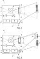
La
La
La
La
La
La
On a représenté sur la
Le dispositif de lecture de code-barres 10 comprend un appareil de lecture de codes-barres 12 ayant un système d'émission de lumière 14 pour illuminer une zone utile dans laquelle on devra présenter le code-barres pour qu'il soit lu par l'appareil.The bar
Le système d'émission de lumière 14 comporte une source de lumière incidente 16, monochromatique ou polychromatique, qui peut par exemple comporter une ou plusieurs sources individuelles, par exemple sous la forme d'une source laser, d'une ou plusieurs diodes électroluminescentes (DEL), voire même d'une source lumineuse à incandescence. De préférence, la source 16 est une source de lumière unique, par exemple une source laser unique ou une diode électroluminescente unique.The light-emitting
Le système d'émission de lumière 14 peut être un système d'émission d'un champ de lumière recouvrant de manière sensiblement uniforme et simultanément l'intégralité d'une zone illuminée utile sans balayage. Alternativement, comme dans le mode de réalisation illustré, le système peut être un système d'émission d'un faisceau lumineux, par exemple sous la forme d'un faisceau laser ou d'un faisceau très fin de lumière collimatée. Typiquement, un faisceau de lumière n'éclaire, à un instant donné, qu'une très faible partie de la zone de travail. Dans l'exemple illustré, la source de lumière incidente 16 est une source laser monochromatique qui émet par exemple un faisceau laser dont la longueur d'onde est de 650 nm.The light-emitting
Le système d'émission de lumière 14 peut par ailleurs comporter un système de conditionnement de lumière incidente 18. Le système de conditionnement 18 peut être très simple et éventuellement être constitué uniquement d'un diaphragme optique 20 destiné à délimiter une zone illuminée. Le système de conditionnement 18 peut par ailleurs comporter un ou plusieurs miroirs réfléchissants 22 pour orienter la lumière émise, par exemple agencé entre la source de lumière incidente 16 et un diaphragme de sortie 20. Cependant, notamment pour les systèmes d'émission de lumière émettant un faisceau lumineux, le système de conditionnement pourra comporter notamment des moyens optiques de collimation/focalisation/délocalisation, tels que des systèmes de lentilles optiques, permettant par exemple de générer à partir d'une source ponctuelle rayonnante un faisceau à rayons parallèles ou quasi parallèles. Le système de conditionnement de lumière incidente 18 peut aussi comporter des moyens de filtrage de la lumière, par exemple pour éliminer certaines fréquences de la lumière fournie par la source de lumière 16. Ces moyens de filtrage peuvent comporter un simple filtre et/ou un filtre interférentiel. Ainsi, le système de conditionnement de lumière incidente 18 transforme la lumière brute fournie par la source 16 en une lumière incidente apte à illuminer un code-barres situé dans une zone de travail utile principale de telle sorte que cette lumière incidente, réfléchie par le code-barres, puisse être récupérée et décodée par l'appareil de manière à récupérer l'information codée par le code-barres.The light-emitting
Par ailleurs, le système de conditionnement de lumière 18 peut comporter, notamment dans le cas d'une source d'émission de lumière incidente émettant un faisceau lumineux, un système de balayage 24 de telle sorte que la lumière incidente balaye une zone définie, de manière répétitive. Le balayage au travers de la zone illuminée utile principale se fait au moins selon une première direction transversale perpendiculaire à la direction de la lumière incidente. Ce balayage est alors unidimensionnel, de sorte que le faisceau lumineux est défléchi de manière à se propager toujours dans un même plan. Il peut être aussi bidimensionnel, par exemple lorsque le faisceau est défléchi de manière à se propager dans un plan et aussi à se propager dans une direction perpendiculaire à ce plan. Dans ce second cas, le faisceau est également défléchi selon une seconde direction transversale, perpendiculaire à la première direction transversale et à la direction de la lumière incidente.Furthermore, the
Dans le premier cas, si une surface opaque et présentée devant la lumière incidente, le faisceau lumineux se déplace donc selon une ligne sur la surface opaque. Dans le second cas, le faisceau se déplace selon une succession de lignes parallèles sur la surface opaque, de telle sorte que si les lignes parallèles sont suffisamment proches, on peut considérer qu'une zone surfacique est illuminée par le faisceau. Dans le mode de réalisation illustré, le système de balayage 24 comporte un prisme octogonal réfléchissant qui est entraîné en rotation, autour d'un axe central parallèle à ces surfaces latérales réfléchissantes, à une vitesse continue. Le prisme est interposé dans le trajet de la lumière incidente entre la source de lumière incidente 16 et un diaphragme de sortie 20 pour créer un balayage unidimensionnel d'une zone illuminée utile par le faisceau lumineux.In the first case, if an opaque surface is presented in front of the incident light, the light beam moves along a line on the opaque surface. In the second case, the beam moves in a succession of parallel lines on the opaque surface, so that if the parallel lines are close enough, we can consider that a surface area is illuminated by the beam. In the illustrated embodiment, the scanning system 24 includes a reflecting octagonal prism which is rotated around a central axis parallel to these reflecting side surfaces at a continuous speed. The prism is interposed in the path of the incident light between the incident
De la sorte, le système d'émission de lumière 14 émet une lumière incidente, selon une direction de lumière incidente, vers une zone illuminée utile, laquelle peut être déterminée en fonction du passage de la lumière incidente à travers le système de conditionnement. La direction principale de la lumière incidente peut être définie comme étant la direction d'un rayon lumineux émis par l'appareil atteignant le centre de la zone illuminée. Dans le cas d'un système d'émission d'un champ de lumière étendue, la lumière peut ne pas être une lumière parallèle mais une lumière divergente ayant la direction centrale comme direction principale dans le centre de la zone illuminée. Dans le cas d'un système d'émission d'un faisceau lumineux avec balayage, le faisceau lumineux présente une direction qui est défléchie de part et d'autre de cette direction principale.In this way, the
De manière générale, une zone utile au sens de l'invention est une zone de l'espace située devant l'appareil pour laquelle la lumière réfléchie par un code-barres situé dans cette zone pourra être récupérée et décodée par l'appareil de manière à récupérer l'information codée par le code-barres. Une zone utile peut généralement être définie par un angle de vision depuis le système de conditionnement optique, cet angle de vision étant un angle plan unidimensionnel ou un angle solide bidimensionnel. Elle peut être généralement définie aussi par une profondeur de champ dans la direction de déplacement de la lumière.In general, a useful area in the sense of the invention is an area of the space in front of the apparatus for which the light reflected by a barcode located in this area can be retrieved and decoded by the apparatus so recovering the coded information by the barcode. A useful area can generally be defined by an angle of view from the optical conditioning system, which viewing angle is a one-dimensional planar angle or a two-dimensional solid angle. It can also be generally defined by a depth of field in the direction of movement of the light.
Ainsi, la zone illuminée utile correspond à la zone illuminée par la source de lumière incidente dans des conditions telles que, si cette lumière est réfléchie par un code-barres disposé dans cette zone utile illuminée, la lumière réfléchie pourra être récupérée et décodée par l'appareil de manière à récupérer l'information codée par le code-barres.Thus, the useful illuminated area corresponds to the area illuminated by the incident light source under conditions such that, if this light is reflected by a barcode disposed in this illuminated useful area, the reflected light can be recovered and decoded by the light source. apparatus so as to recover the information encoded by the barcode.
L'appareil 12 de lecture de codes-barres comporte par ailleurs un capteur photoélectrique 26, comprenant un ou plusieurs éléments de capteur, pour convertir une lumière réfléchie récupérée en un signal électrique représentatif de la lumière réfléchie récupérée. Cette lumière réfléchie est vue par le capteur 26 au travers d'un système de récupération de lumière 28, comportant notamment un système de conditionnement de lumière réfléchie 30. Le système de récupération de lumière 28 est capable de récupérer une lumière réfléchie d'une zone de vision utile, par exemple une lumière réfléchie par un code-barres. La zone de vision utile est donc associée au capteur 26 et au système de conditionnement de lumière réfléchie 30 comme étant la zone de l'espace pour laquelle une image située dans cette zone peut être vue avec un niveau de résolution suffisant par le capteur.The
Le système de conditionnement de lumière réfléchie 30 peut notamment comporter un système de lentilles optiques, notamment un système convergent, permettant de focaliser sur le capteur 26 l'image d'un objet tel qu'un code-barres positionné dans la zone de vision utile, avec une netteté suffisante pour que cette image puisse être décodée par l'appareil de manière à récupérer l'information codée par le code-barres.The reflected
L'appareil de lecture de code-barres 12 peut par ailleurs comporter un dispositif de traitement de signal 32, qui peut comporter notamment des filtres analogiques et/ou numériques, un ou plusieurs convertisseurs analogiques-numériques, éventuellement un microprocesseur et de la mémoire, etc..., pour convertir le signal électrique représentatif de la lumière réfléchie récupérée en données numériques. L'appareil 12 comporte généralement par ailleurs une sortie 34, analogique ou numérique, par laquelle le signal électrique représentatif ou les données numériques converties à partir de ce signal électrique représentatif peuvent être communiquées à un système de traitement informatique. Cette liaison peut être une liaison filaire ou une liaison sans fil.The bar
On peut définir pour le dispositif de lecture de codes-barres une zone de travail utile principale s'étendant selon une direction de profondeur correspondant à la direction de la lumière incidente et selon au moins une première direction transversale perpendiculaire à la direction de lumière incidente. Cette zone de travail utile principale est comprise dans l'intersection de la zone illuminée utile et de la zone de vision utile. Cette zone de travail utile principale est telle que, lorsqu'un premier code-barres, ayant une densité inférieure à un niveau de seuil de densité, est disposé dans la zone de travail utile principale, ce premier code-barres peut être illuminé par le système d'émission de lumière et la lumière réfléchie par ce premier code-barres peut être convertie en données numériques par le capteur et le convertisseur numérique, sans devoir passer par un système optique auxiliaire.A main working working area extending in a direction of depth corresponding to the direction of the incident light and in at least a first transverse direction perpendicular to the incident light direction can be defined for the bar code reading device. This main working area is included in the intersection of the useful illuminated area and the useful area of vision. This main working area is such that when a first bar code, having a density less than a density threshold level, is disposed in the main working area, this first barcode can be illuminated by the light emission system and the light reflected by this first barcode can be converted into digital data by the sensor and the digital converter, without having to go through an auxiliary optical system.
On a illustré sur la
La zone de vision utile est dite interceptée par le système optique auxiliaire par référence à la trajectoire du rayon lumineux provenant d'un objet situé dans la zone de vision utile et atteignant le capteur 26 au travers du système de récupération de lumière sans passer par le dit système optique auxiliaire. La zone de vision utile est dite interceptée par le système optique auxiliaire si le système optique auxiliaire est situé sur la trajectoire de ce rayon lumineux.The useful vision area is said to be intercepted by the auxiliary optical system by reference to the path of the light beam coming from an object situated in the useful vision area and reaching the
Le système optique auxiliaire 36 peut comprendre un seul élément optique, ou plusieurs éléments optiques, notamment agencés en série dans la trajectoire du rayon lumineux.The auxiliary
De préférence, le système optique auxiliaire 36 est un système optique convergent. Dans l'exemple illustré, ce système optique est une simple lentille optique convergente, de préférence une lentille mince. Plus précisément, la lentille mince peut-être une lentille plan convexe, soit cylindrique soit sphérique.Preferably, the auxiliary
Comme le système optique auxiliaire 36 est agencé dans la zone de vision utile, il crée, derrière lui selon la direction de la lumière incidente, une zone de vision utile auxiliaire. Cette zone de vision utile auxiliaire correspond à la zone de l'espace qui est vue par le capteur au travers du système optique auxiliaire 36 en série avec le système de conditionnement de la lumière réfléchie 30. Cette zone de vision utile auxiliaire est telle que lorsqu'un second code-barres est disposé dans cette zone, la lumière réfléchie par ce second code-barres peut être convertie en données numériques par le capteur et le dispositif de traitement de signal en traversant successivement le système optique auxiliaire 36 et le système de conditionnement optique de lumière réfléchie 30. Since the auxiliary
De préférence, le système optique auxiliaire 36 est agencé à l'extérieur du système de conditionnement de lumière réfléchie 30 et, selon une direction de lumière réfléchie, du même côté du système de conditionnement de lumière réfléchie 30 que la zone de vision utile, à l'opposé du côté du capteur 26. Dans ce cas aussi, le système optique auxiliaire 36 est donc à distance du capteur au sens qu'il n'est pas en contact avec celui-ci.Preferably, the auxiliary
Dans l'exemple illustré sur les figures, le système optique auxiliaire définit une zone de vision utile réduite, non interceptée par le système optique auxiliaire, qui a une étendue suffisante pour qu'un premier code-barres disposé dans la zone de vision utile réduite soit illuminé par le système d'émission de lumière, et pour que la lumière réfléchie par ledit code-barres soit reçue par le capteur photoélectrique sans être interceptée par le système optique auxiliaire 36. De préférence, la zone de vision utile réduite représente, en étendue angulaire telle que vue depuis l'entrée du système de récupération de lumière réfléchie 28, plus de 50% de la zone de vision utile principale, de préférence plus de 75%.In the example illustrated in the figures, the auxiliary optical system defines a reduced area of useful vision, not intercepted by the auxiliary optical system, which has a sufficient extent for a first barcode disposed in the area of reduced useful vision. is illuminated by the light-emitting system, and for the light reflected by said bar-code to be received by the photoelectric sensor without being intercepted by the auxiliary
De préférence, comme illustré sur la
Par ailleurs, le dispositif de lecture de codes-barres est agencé de telle sorte que le système optique auxiliaire 36 est capable de transmettre au capteur 26 une image d'un code-barres complet 40 disposé dans la zone de vision utile auxiliaire. Autrement dit, la zone de vision auxiliaire correspond un angle de vision suffisant pour que dans sa profondeur de champ, l'étendue de l'angle de vision puisse accommoder un code-barres complet, en tous les cas au moins un code-barres présentant une densité supérieure à un niveau de seuil de densité.Furthermore, the barcode reading device is arranged such that the auxiliary
Dans l'exemple illustré, le système optique auxiliaire 36 est agencé à l'intérieur de la zone illuminée utile de telle sorte qu'une portion de la zone illuminée utile est interceptée par le système optique auxiliaire et définit une zone illuminée auxiliaire qui est illuminée au travers du système optique auxiliaire. Cette zone illuminée utile auxiliaire s'étend derrière le système optique auxiliaire 36 dans le sens de propagation de la lumière incidente, c'est-à-dire derrière le système optique auxiliaire 36 vu depuis la source de lumière incidente, ou encore sur la droite du système auxiliaire optique 36 en considérant la
Dans le cas où, comme illustré sur les figures, la lumière incidente comporte au moins un faisceau de lumière incidente, ce faisceau de lumière forme, sur un objet opaque agencé dans la zone de travail utile une tache lumineuse contenue de préférence dans un diamètre d'environ 1 mm. Sur la profondeur de champ, ce diamètre peut varier dans la mesure où un tel faisceau n'est jamais parfaitement parallèle, y compris pour le cas d'un faisceau laser. Dans tous les cas, il sera considéré que le faisceau est focalisé par le système d'émission de lumière jusqu'à une première taille minimale de focalisation dans la zone de travail utile principale comprise dans la zone de vision utile et dans la zone illuminée utile. Selon un aspect de invention, lorsque la lumière incidente comporte un faisceau de lumière incidente, et que le système optique auxiliaire intercepte la zone illuminée utile, le système optique auxiliaire focalise le faisceau de lumière incidente jusqu'à une seconde taille minimale de focalisation dans une zone de travail utile auxiliaire comprise dans la zone de vision utile auxiliaire et dans la zone illuminée auxiliaire, ladite seconde taille minimale de focalisation étant plus petite que la première taille minimale de focalisation. De la sorte, le faisceau de lumière incidente, qui en l'absence de système optique auxiliaire, serait insuffisamment précis pour permettre le décodage d'un code-barres ayant une densité supérieure à un niveau de seuil de densité, pourra, grâce à sa focalisation à travers le système optique auxiliaire, être capable de permettre la lecture d'un tel code-barres situé dans la zone de travail utile auxiliaire.In the case where, as illustrated in the figures, the incident light comprises at least one incident light beam, this light beam forms, on an opaque object arranged in the useful working area, a light spot preferably contained in a diameter of about 1 mm. On the depth of field, this diameter can vary inasmuch as such a beam is never perfectly parallel, including for the case of a laser beam. In any case, it will be considered that the beam is focused by the light-emitting system to a first minimum focusing size in the main useful working area in the useful vision area and in the illuminated area of interest. . According to one aspect of the invention, when the incident light has an incident light beam, and the auxiliary optical system intercepts the useful illuminated area, the auxiliary optical system focuses the incident light beam to a second minimum focus size in a auxiliary working area included in the auxiliary vision area and in the auxiliary illuminated area, said second minimum focusing size being smaller than the first minimum focusing size. In this way, the incident light beam, which in the absence of auxiliary optical system, would be insufficiently precise to allow the decoding of a bar code having a density greater than a density threshold level, can, thanks to its focusing through the auxiliary optical system, being able to allow the reading of such a bar code located in the auxiliary working area.
De préférence, le système optique auxiliaire 36 est agencé à l'extérieur du système de conditionnement de lumière incidente, selon la direction de lumière incidente, d'un même côté du système de conditionnement de lumière incidente 18 que la zone de travail utile.Preferably, the auxiliary
De préférence, le système optique auxiliaire a un plan focal objet situé derrière la zone de travail utile auxiliaire. En d'autres termes, on placera un code-barres de haute densité de préférence derrière le système optique auxiliaire vu depuis l'appareil de lecture de code-barres.Preferably, the auxiliary optical system has an object focal plane located behind the auxiliary working area. In other words, a high density barcode will preferably be placed behind the auxiliary optical system as seen from the bar code reader.
Le système optique auxiliaire peut être agencé dans la zone de travail utile principale, ou à proximité de celle-ci dans la direction de la profondeur de champ. De préférence, le système optique auxiliaire 36 est le seul système optique traversé par la lumière incidente et par la lumière réfléchie dans la zone de travail utile principale. De préférence, si le système optique auxiliaire comprend plusieurs éléments optiques en série, les lumières incidente et réfléchie traversent les mêmes éléments optiques du système optique auxiliaire.The auxiliary optical system may be arranged in or near the main useful working area in the direction of depth of field. Preferably, the auxiliary
Dans l'exemple illustré, le système optique auxiliaire 36 a une distance focale fixe, ce qui permet d'utiliser des composants optiques simples. De même, le système optique auxiliaire 36 a une position fixe par rapport au capteur 26, mais aussi de préférence par rapport à la source 16, pendant le fonctionnement du dispositif. De même, l'intégralité du système de récupération de lumière a une position fixe par rapport au capteur pendant le fonctionnement du dispositif. Autrement dit, le dispositif est capable de lire un premier code-barres situé dans la zone de travail utile réduite et/ou un second code-barres situé dans la zone de travail utile auxiliaire sans qu'il ne soit nécessaire de déplacer le système optique auxiliaire, et de préférence sans avoir à modifier le fonctionnement du système de récupération de lumière et/ou le système de conditionnement de la lumière incidente. De plus, dans l'exemple illustré, ni le capteur, ni la source de lumière incidente n'ont besoin d'être déplacés lors du fonctionnement du dispositif pour assurer la lecture du premier ou du second code-barres tels que mentionnés ci-dessus.In the illustrated example, the auxiliary
Dans le cadre d'un dispositif avec système d'émission d'un faisceau de lumière à balayage, le faisceau de lumière incidente est balayé au travers de la zone de travail principale selon au moins la première direction transversale entre une première position angulaire et une seconde position angulaire. Dans ce cas, le système optique auxiliaire est de préférence agencé de manière à être situé sur le passage du faisceau de lumière incidente entre une position intermédiaire et l'une des première ou seconde positions angulaires. Autrement dit, le système optique auxiliaire 36 n'intercepte qu'une partie de la zone illuminée utile.In the case of a device with a scanning light beam emission system, the incident light beam is scanned through the main work area in at least the first transverse direction between a first angular position and a second angular position. In this case, the auxiliary optical system is preferably arranged to be located on the passage of the incident light beam between an intermediate position and one of the first or second angular positions. In other words, the auxiliary
Dans l'exemple de réalisation telle qu'illustré sur la
Dans une version de l'invention, comme celle illustré sur les figures, le système optique auxiliaire est agencé à l'extérieur du boîtier. Comme on le verra par la suite, le système optique auxiliaire peut même ne pas être fixé au boîtier. On comprend donc que le système optique auxiliaire est indépendant de l'appareil de lecture de codes-barres 12, lequel peut parfaitement fonctionner sans le système optique auxiliaire, au moins pour assurer la lecture de codes-barres présentant une densité inférieure à un niveau de seuil de densité pour cet appareil. Autrement dit, le niveau de seuil de densité est un niveau au-dessus duquel l'appareil de lecture de codes-barres n'est pas capable de lire un code-barres en l'absence du système optique auxiliaire.In one version of the invention, like that illustrated in the figures, the auxiliary optical system is arranged outside the housing. As will be seen later, the auxiliary optical system may not even be attached to the housing. It is therefore understood that the auxiliary optical system is independent of the bar
Le dispositif de lecture de codes-barres selon l'invention peut donc lire des codes-barres qui peuvent se présenter à des distances différentes de l'appareil de lecture, qui peuvent présenter des caractéristiques de densité différente, et qui peuvent par ailleurs dans certains cas se présenter simultanémentThe bar code reading device according to the invention can therefore read bar codes which may be at different distances from the reading apparatus, which may have different density characteristics, and which may also in certain case arise simultaneously
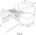
Il sera maintenant décrit une application particulière d'un dispositif de lecture à code-barres selon l'invention. En effet, un tel dispositif de lecture à code-barres peut être utilisé dans une machine pour l'analyse automatisée d'un échantillon, notamment une machine du type commercialisé par la demanderesse sous la dénomination commerciale «VIDAS 3 ». Ce type de machine permet de réaliser des analyses biologiques sur des échantillons biologiques de manière automatisée, et avec la possibilité de pratiquer, sur une même machine, différentes analyses sur un même échantillon ou sur des échantillons différents.It will now be described a particular application of a barcode reading device according to the invention. Indeed, such a barcode reading device can be used in a machine for automated analysis of a sample, including a machine of the type marketed by the applicant under the trade name "VIDAS 3". This type of machine makes it possible to perform biological analyzes on biological samples in an automated manner, and with the possibility of practicing, on the same machine, different analyzes on the same sample or on different samples.
Une machine de ce type est illustrée en vue de face sur la
Sur la
Par ailleurs, on distingue sur la
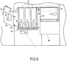
On a illustré sur la
Sur la
Sur la
De préférence, le dispositif est installé sur la machine de manière à être capable de lire, sur au moins un premier tiroir, un premier code-barres ayant une densité inférieure au niveau de seuil de densité, et, sur au moins un second tiroir, au travers du dispositif optique auxiliaire, un second code-barres ayant une densité supérieure au niveau de seuil de densité. Par exemple, le premier tiroir peut être un tiroir primaire 56 et le second tiroir peut-être le tiroir secondaire 58. Preferably, the device is installed on the machine so as to be able to read, on at least one first drawer, a first barcode having a density lower than the density threshold level, and, on at least one second drawer, through the auxiliary optical device, a second bar code having a density higher than the density threshold level. For example, the first drawer may be a
Dans l'exemple illustré, on voit ainsi que l'appareil de lecture de codes-barres 12 est monté sur une platine 80 fixée sur la paroi avant 74 du châssis 70. L'appareil est donc reçu dans l'espace entre la face avant verticale 74 du châssis 70 et la face avant de la machine. L'appareil 12 est disposé de telle sorte que les directions principales des lumières incidente et réfléchie émise et reçue par l'appareil soient contenues dans un plan frontal contenant les directions verticale et latérale, perpendiculaires à la direction de coulissement des tiroirs 56, 58. Ainsi, les tiroirs se déplacent entre leurs positions de chargement et leurs positions d'utilisation selon une trajectoire de tiroirs qui est perpendiculaire à la direction de lumière incidente et à la première direction transversale de balayage.In the example illustrated, it is thus seen that the
Dans l'exemple illustré, la zone de travail utile principale de l'appareil 12 s'étend, dans le plan frontal, sur une étendue angulaire d'environ 60° de manière à couvrir intégralement ou quasi intégralement un volume traversé par chacun des tiroirs 56, 58. Dans l'exemple illustré, l'appareil 12 est positionné en haut à gauche de la baie de chargement formé par les tiroirs 56, 58, et légèrement en avant par rapport à la paroi avant 74. Toutefois, l'appareil 12 est agencé à l'intérieur de la carrosserie de la machine, et notamment derrière une façade avant. Selon un aspect particulier, lorsque l'un des tiroirs primaires 56 est en position d'utilisation, repoussé à fond à l'intérieur de son logement 72, sa fenêtre de préhension 64 est agencée pour correspondre à la position du plan frontal balayé par la lumière incidente. Ainsi, lorsqu'un tiroir primaire ou un tiroir secondaire se trouve dans une position de chargement ou une position intermédiaire, sa face latérale tournée vers la gauche, donc tournée vers l'appareil de lecture de code-barres 12, est donc exposée à la lumière incidente de telle sorte qu'un code-barres positionné sur cette face latérale pourra être illuminé par l'appareil et pourra réfléchir une lumière susceptible d'être récupérée et décodée par l'appareil 12. Si le tiroir concerné n'est pas le tiroir primaire 56 situé le plus à gauche, c'est-à-dire celui situé le plus près de l'appareil 12 et donc de la source de lumière 16, l'illumination du code-barres et la récupération de la lumière réfléchie par le code-barres se fait au travers de la ou des fenêtres de préhension 63 du ou des tiroir(s) primaire(s) situé(s) à gauche de ce tiroir.In the illustrated example, the main useful working area of the
À titre principal, l'appareil de lecture optique 14 est utilisé pour lire et décoder des codes-barres portés par l'un des trois tiroirs primaires 56. De la sorte, l'agencement est tel que la zone occupée par ces tiroirs primaires 56 dans le plan frontal de balayage de la lumière incidente coïncide avec la zone de travail utile principale de l'appareil de lecture à code-barres 12. In principle, the
Comme on peut le voir plus particulièrement sur la
Cependant, on peut voir que le système optique auxiliaire 36 est, dans le plan frontal, agencé de manière à n'intercepter qu'une très faible partie de la zone illuminée utile et de la zone de vision utile de l'appareil 12. La zone dans laquelle se situe le système optique auxiliaire correspond sensiblement à une portion angulaire d'extrémité de la zone de travail utile. De la sorte, la zone de travail utile réduite, qui correspond à celle qui n'est pas interceptée par le système optique auxiliaire 36, s'étend en dessous du système optique auxiliaire 36. La zone de travail utile auxiliaire, qui correspond à la zone pour laquelle un code-barres est illuminé à travers le système optique auxiliaire 36 et pour laquelle la lumière réfléchie par le code-barres est vue par le capteur 26 également au travers du système optique auxiliaire, correspond sensiblement à une partie haute du tiroir 58. De la sorte, un code-barres agencé sur le tiroir secondaire 58 dans cette partie haute sera vu par l'appareil de lecture de code-barres au travers du système auxiliaire optique 36. Au contraire, un code-barres agencé sur une partie basse du tiroir 58 sera ainsi agencé dans la zone de travail utile principale réduite, et sera vu par l'appareil 12 sans passage de la lumière incidente ni de la lumière réfléchie au travers du système optique principal. Ainsi, dans au moins une position de lecture de code-barres du second tiroir, un code-barres situé sur le second tiroir est agencé dans la zone de travail utile principale.However, it can be seen that the auxiliary
De préférence, dans la mesure où l'appareil de lecture de codes-barres 12 est un appareil à balayage laser unidimensionnel, les codes-barres sont agencés sur les tiroirs de manière à s'étendre selon la première direction transversale de balayage. En l'occurrence, comme la direction de balayage est une direction contenue dans le plan frontal vertical, le code-barres est donc de préférence agencé avec les barres et les intervalles qui sont espacés l'un de l'autre selon la direction verticale, les barres étant donc des barres horizontales.Preferably, since the bar
Dans l'exemple illustré sur les figures, la lentille plan-convexe utilisée en tant que système optique auxiliaire 36 est une lentille dont la surface convexe est une surface cylindrique dont le rayon de courbure est de 26,7 mm. La hauteur de la lentille selon la première direction transversale de balayage, en l'occurrence la direction verticale de la machine, est par exemple de 18 mm. L'axe de la surface cylindrique de la lentille est agencé perpendiculairement à la première direction transversale de balayage, de sorte qu'il est agencé horizontalement, parallèlement à la direction de coulissement des tiroirs. La largeur de la lentille selon l'axe de la surface cylindrique est par exemple de 12 mm. La distance focale de la lentille est de 25 mm environ et la lentille est positionnée sur la machine de manière à être à moins de 20 mm de la surface latérale du tiroir 58 qui porte le code-barres. Par ailleurs, la lentille est positionnée à environ 150 mm de l'appareil de lecture de code-barres 12. Avec un tel dispositif, des essais ont montré qu'il était possible de lire, sur la face latérale du tiroir secondaire 58, des codes-barres ayant une densité de 3,3 mils (millièmes de pouce) à l'aide d'un appareil de lecture à code-barres 12 dont la résolution, en l'absence de dispositif optique auxiliaire, ne permet pas de lire des codes-barres ayant une densité supérieure à 10 mils, c'est-à-dire ne permet pas de lire des codes-barres dont des barres sont rapprochées de moins de 10/1000 de pouce.In the example illustrated in the figures, the plano-convex lens used as an auxiliary
L'invention n'est pas limitée aux exemples décrits et représentés car diverses modifications peuvent y être apportées sans sortir de son cadre.The invention is not limited to the examples described and shown because various modifications can be made without departing from its scope.
Claims (22)
- A barcode reader device (10) comprising a barcode reader apparatus (12) having:a) a light-emitting system (14), having an incident light source (16), capable of emitting an incident light, toward a useful illuminated zone;b) a light recovery system (28) having a system for conditioning reflected light (30) capable of recovering light reflected by a useful viewing zone through the reflected light conditioning system (30);c) a photoelectric sensor (26) for converting the reflected light recovered through the reflected light conditioning system (30) into an electric signal representative of the recovered reflected light;characterized in that the device (10) comprises an auxiliary optical system (36) that is arranged permanently in the useful viewing zone, at a distance from the sensor (26), and in series with the reflected light conditioning system (30) such that a portion, but not all, of the useful viewing zone is intercepted by the auxiliary optical system (36).
- The barcode reader device according to claim 1, characterized in that the auxiliary optical system (36) defines a reduced useful viewing zone, not intercepted by the auxiliary optical system, which has a sufficient span for a first barcode (38) positioned in the reduced useful viewing zone to be illuminated by the light-emitting system, and for the light reflected by said barcode (38) to be recovered by the photoelectric sensor without being intercepted by the auxiliary optical system.
- The barcode reader device according to one of claims 1 or 2, characterized in that the device (10) is arranged such that the sensor (26) is capable of simultaneously receiving light reflected by a first barcode (38) in the reduced useful viewing zone, without passing through the auxiliary optical system (36), and light reflected by a second barcode (40) in the auxiliary useful viewing zone, through the auxiliary optical system (36).
- The barcode reader device according to any one of the preceding claims, characterized in that the auxiliary optical system (36) is arranged outside the reflected light conditioning system (30) and, in a reflected light direction, on the same side of the reflected light conditioning system (30) as the main useful viewing zone, opposite the side of the sensor (26).
- The barcode reader device according to any one of the preceding claims, characterized in that the auxiliary optical system (36) is capable of sending the sensor (26) an image of a complete barcode arranged in the auxiliary useful viewing zone.
- The barcode reader device according to any one of the preceding claims, characterized in that the auxiliary optical system (36) is arranged inside the useful illuminated zone such that a portion of the useful illuminated zone is intercepted by the auxiliary optical system (36) and defines an auxiliary illuminated zone that is illuminated through the auxiliary optical system (36).
- The barcode reader device according to any one of the preceding claims, characterized in that the auxiliary optical system (36) is arranged outside an incident light conditioning system (18) of the apparatus (12), in the incident light direction, on a same side of the incident light conditioning system (18) as the useful illuminated zone.
- The barcode reader device according to any one of the preceding claims, characterized in that the auxiliary optical system (36) is a convergent optical system.
- The barcode reader device according to claim 8, characterized in that the incident light includes at least one incident light beam that is focused by the light-emitting system (14) up to a first minimum focusing size and a main useful working zone comprised in the useful viewing zone and the useful illuminated zone, and in that the auxiliary optical system (36) focuses the incident light beam up to a second minimum focusing size in an auxiliary useful working zone comprised in the auxiliary useful viewing zone and in an auxiliary illuminated zone, said second minimum focusing size being smaller than the first minimum focusing size.
- The barcode reader device according to any one of the preceding claims, characterized in that the auxiliary optical system (36) has an object focal plane located behind the auxiliary useful working zone.
- The barcode reader device according to any one of the preceding claims, characterized in that the auxiliary optical system (36) is arranged in the main useful working zone.
- The auxiliary barcode reader device according to any one of the preceding claims, characterized in that the auxiliary optical system (36) has a fixed focal distance.
- The barcode reader device according to any one of the preceding claims, characterized in that the auxiliary optical system (36) has a fixed position relative to the sensor during the operation of the device.
- The barcode reader device according to any one of the preceding claims, characterized in that the entire light recovery system (28) has a fixed position relative to the sensor (26) during the operation of the device.
- The barcode reader device according to any one of the preceding claims, characterized in that the barcode reader apparatus (12) includes a housing (42) that contains at least the light-emitting system (14), the light recovery system (28) and the sensor (26), and in that the auxiliary optical system (36) is arranged outside the housing (42).
- A machine (50) for the automated analysis of a specimen, comprising at least one slide (56, 58) on which at least one element can be loaded, the slide being movable from a loading position to a usage position, characterized in that the machine comprises a barcode reader device (10) according to any one of the preceding claims for reading at least a first barcode (38) having a density below a density threshold level and a second barcode having a density above a density threshold level.
- The machine according to claim 16 combined with claim 8, characterized in that it includes several slides arranged side by side and movable independently of one another between a loading position and a usage position, and in that the barcode reader device (10) is capable of reading, on a first slide (56), a first barcode (38) having a density below the density threshold level, and, on a second slide (58), through the convergent auxiliary optical system (36), a second barcode (40) having a density above the density threshold level.
- The machine according to claim 17, characterized in that along the incident light direction, the first slide (56) is arranged closer to the incident light source (16) than the second slide (58).
- The machine according to one of claims 17 or 18, characterized in that, in at least a first barcode reading position of the first slide (56), the first barcode is arranged in a main useful viewing zone and, in at least a first barcode reading position of the second slide (58), the second barcode is arranged in an auxiliary useful viewing zone.
- The machine according to one of claims 17 to 19, characterized in that, in at least one barcode reading position of the second slide (58), a barcode located on the second slide is arranged in the main useful viewing zone.
- The machine according to one of claims 16 to 20, characterized in that a housing (42) of the barcode reading apparatus (14) and the auxiliary optical system (36) are fastened independently of one another on a frame (70) of the machine (50).
- The machine according to one of claims 16 to 21, characterized in the housing (42) of the barcode reading apparatus (12) and the auxiliary optical system (36) are arranged at a distance on the machine (70) such that at least one slide (56) extends between the housing (42) of the barcode reading apparatus (12) in the auxiliary optical system (36).
Applications Claiming Priority (2)
| Application Number | Priority Date | Filing Date | Title |
|---|---|---|---|
| FR1458577A FR3025913B1 (en) | 2014-09-12 | 2014-09-12 | BAR CODE READING DEVICE AND MACHINE FOR AUTOMATED ANALYSIS OF A SAMPLE COMPRISING SUCH A DEVICE |
| PCT/FR2015/052376 WO2016038291A1 (en) | 2014-09-12 | 2015-09-08 | Barcode-reading device and machine including such a device for automated analysis of a sample |
Publications (2)
| Publication Number | Publication Date |
|---|---|
| EP3192004A1 EP3192004A1 (en) | 2017-07-19 |
| EP3192004B1 true EP3192004B1 (en) | 2018-09-05 |
Family
ID=51842599
Family Applications (1)
| Application Number | Title | Priority Date | Filing Date |
|---|---|---|---|
| EP15778988.4A Active EP3192004B1 (en) | 2014-09-12 | 2015-09-08 | Reading device and bar code machine including such device for automatic analysis of a sample |
Country Status (5)
| Country | Link |
|---|---|
| US (1) | US10002276B2 (en) |
| EP (1) | EP3192004B1 (en) |
| CN (1) | CN106687988B (en) |
| FR (1) | FR3025913B1 (en) |
| WO (1) | WO2016038291A1 (en) |
Family Cites Families (19)
| Publication number | Priority date | Publication date | Assignee | Title |
|---|---|---|---|---|
| US4591242A (en) | 1984-02-13 | 1986-05-27 | International Business Machines Corp. | Optical scanner having multiple, simultaneous scan lines with different focal lengths |
| US5175421A (en) | 1989-05-01 | 1992-12-29 | International Business Machines Corporation | Dual depth of field deflector for bar code scanners |
| EP0524349A1 (en) | 1991-07-08 | 1993-01-27 | Opticon Sensors Europe B.V. | Dual-focus scanner and such a scanner used as wandtype symbol code reader |
| IL118507A (en) * | 1992-12-04 | 2000-07-16 | Psc Inc | Optical symbol (bar code) reading systems and devices |
| JPH06333074A (en) | 1993-05-25 | 1994-12-02 | Nippondenso Co Ltd | Optical information reader |
| JP3698794B2 (en) * | 1995-02-27 | 2005-09-21 | オリンパス株式会社 | Optical scanner |
| US6415982B2 (en) * | 1995-03-20 | 2002-07-09 | Symbol Technologies, Inc. | Triggered data collector and data transmitter |
| US6360949B1 (en) * | 1995-10-10 | 2002-03-26 | Symbol Technologies, Inc. | Retro-reflective scan module for electro-optical readers |
| US6824059B2 (en) * | 2002-04-30 | 2004-11-30 | Hewlett-Packard Development Company, L.P. | Apparatus for capturing images and barcodes |
| US6820811B1 (en) | 2002-12-16 | 2004-11-23 | Ncr Corporation | Dual focal length bar code scanner |
| US6909080B2 (en) | 2002-12-17 | 2005-06-21 | Symbol Technologies, Inc. | Arrangement for and method of imaging targets at plural focal planes |
| US7204420B2 (en) * | 2004-08-31 | 2007-04-17 | Symbol Technologies, Inc. | Scanner and method for eliminating specular reflection |
| US7562826B2 (en) * | 2005-09-12 | 2009-07-21 | Symbol Technologies Inc | Scan engine with dual chip architecture for use in electro-optical readers |
| US8488210B2 (en) * | 2006-06-20 | 2013-07-16 | Datalogic ADC, Inc. | Imaging scanner with multiple image fields |
| US20090127341A1 (en) * | 2007-11-19 | 2009-05-21 | Xiangyang Feng | Bar-code reading tool |
| CN201218951Y (en) * | 2008-04-30 | 2009-04-08 | 凌通科技股份有限公司 | Apparatus for bar code recognition by using light sensation characteristic of LED |
| US7762466B2 (en) * | 2008-12-18 | 2010-07-27 | Symbol Technologies, Inc. | Two position zoom lens assembly for an imaging-based bar code reader |
| US8613393B2 (en) * | 2010-06-16 | 2013-12-24 | Symbol Technologies, Inc. | Optical scanner with customer interface |
| US8646690B2 (en) * | 2012-02-06 | 2014-02-11 | Cognex Corporation | System and method for expansion of field of view in a vision system |
-
2014
- 2014-09-12 FR FR1458577A patent/FR3025913B1/en active Active
-
2015
- 2015-09-08 EP EP15778988.4A patent/EP3192004B1/en active Active
- 2015-09-08 CN CN201580048683.0A patent/CN106687988B/en active Active
- 2015-09-08 US US15/508,165 patent/US10002276B2/en active Active
- 2015-09-08 WO PCT/FR2015/052376 patent/WO2016038291A1/en active Application Filing
Also Published As
| Publication number | Publication date |
|---|---|
| US20170255804A1 (en) | 2017-09-07 |
| FR3025913B1 (en) | 2016-09-09 |
| WO2016038291A1 (en) | 2016-03-17 |
| CN106687988B (en) | 2020-03-10 |
| US10002276B2 (en) | 2018-06-19 |
| FR3025913A1 (en) | 2016-03-18 |
| CN106687988A (en) | 2017-05-17 |
| EP3192004A1 (en) | 2017-07-19 |
Similar Documents
| Publication | Publication Date | Title |
|---|---|---|
| US7626769B2 (en) | Extended depth of field imaging system using chromatic aberration | |
| US20140254894A1 (en) | Latent fingerprint detectors and fingerprint scanners therefrom | |
| EP0746746A1 (en) | Image multispectral sensing | |
| WO1998018098A1 (en) | Camera for decoding machine readable images having diffuser | |
| FR2921719A1 (en) | Physical object e.g. apple, three-dimensional surface's synthesis image creating method for e.g. industrial farm, involves calculating depth coordinate measured at axis for each point of dusty seeds from projection of point on surface | |
| EP3963284B1 (en) | Line for inspecting empty glass containers | |
| FR3055447A1 (en) | MORE VISIBLE VIEWING BRAND FOR OPTICAL READER | |
| KR20180126927A (en) | A eight-channel ridar | |
| US8556179B2 (en) | Motion tolerant bar code reader | |
| EP2356429B1 (en) | Device for analyzing a polyphase mixture via a light beam backscattered by said mixture | |
| EP2960642A1 (en) | Optical chamber for a gas detection device | |
| EP3192004B1 (en) | Reading device and bar code machine including such device for automatic analysis of a sample | |
| WO2000031962A1 (en) | Fluorescence-activated image acquisition apparatus and imaging system comprising same | |
| US20160320312A1 (en) | Gemstone imaging apparatus | |
| FR2924517A1 (en) | Semi structured document's e.g. cheque, automatic authentification and digitization device for e.g. airport, has illumination system and sensor that are placed in zones such that light is not incident on reading surface for capturing image | |
| EP1147405B1 (en) | Method and device for detecting crizzling in translucent or transparent material | |
| FR2594982A1 (en) | Method of producing optically-read codes, method of reading the said codes and installation for implementing the method | |
| FR3022999A1 (en) | OPTICAL CHAMBER FOR GAS DETECTION DEVICE | |
| WO2009074750A2 (en) | Device for three-dimensional digitisation | |
| EP1077641B1 (en) | Compact optical fingerprint sensor | |
| US9922233B1 (en) | Thin type optical fingerprint sensor | |
| FR3055559A1 (en) | DEVICE FOR DETECTING, STORING AND ORDERING SAMPLE BLADES. | |
| EP0895202A1 (en) | Improvements by redundancy to optical recognition systems in reverse vending machines | |
| FR2977695A1 (en) | ULTRA COMPACT SCANNER WITH FIXED READING | |
| EP1734382A1 (en) | Device for determining the position of a moving object with respect to a fixed point |
Legal Events
| Date | Code | Title | Description |
|---|---|---|---|
| PUAI | Public reference made under article 153(3) epc to a published international application that has entered the european phase |
Free format text: ORIGINAL CODE: 0009012 |
|
| 17P | Request for examination filed |
Effective date: 20170220 |
|
| AK | Designated contracting states |
Kind code of ref document: A1 Designated state(s): AL AT BE BG CH CY CZ DE DK EE ES FI FR GB GR HR HU IE IS IT LI LT LU LV MC MK MT NL NO PL PT RO RS SE SI SK SM TR |
|
| AX | Request for extension of the european patent |
Extension state: BA ME |
|
| DAV | Request for validation of the european patent (deleted) | ||
| DAX | Request for extension of the european patent (deleted) | ||
| GRAP | Despatch of communication of intention to grant a patent |
Free format text: ORIGINAL CODE: EPIDOSNIGR1 |
|
| INTG | Intention to grant announced |
Effective date: 20180417 |
|
| GRAS | Grant fee paid |
Free format text: ORIGINAL CODE: EPIDOSNIGR3 |
|
| GRAA | (expected) grant |
Free format text: ORIGINAL CODE: 0009210 |
|
| AK | Designated contracting states |
Kind code of ref document: B1 Designated state(s): AL AT BE BG CH CY CZ DE DK EE ES FI FR GB GR HR HU IE IS IT LI LT LU LV MC MK MT NL NO PL PT RO RS SE SI SK SM TR |
|
| REG | Reference to a national code |
Ref country code: GB Ref legal event code: FG4D Free format text: NOT ENGLISH |
|
| REG | Reference to a national code |
Ref country code: CH Ref legal event code: EP |
|
| REG | Reference to a national code |
Ref country code: AT Ref legal event code: REF Ref document number: 1038679 Country of ref document: AT Kind code of ref document: T Effective date: 20180915 |
|
| REG | Reference to a national code |
Ref country code: IE Ref legal event code: FG4D Free format text: LANGUAGE OF EP DOCUMENT: FRENCH |
|
| REG | Reference to a national code |
Ref country code: DE Ref legal event code: R096 Ref document number: 602015015831 Country of ref document: DE |
|
| REG | Reference to a national code |
Ref country code: FR Ref legal event code: PLFP Year of fee payment: 4 |
|
| REG | Reference to a national code |
Ref country code: NL Ref legal event code: MP Effective date: 20180905 |
|
| REG | Reference to a national code |
Ref country code: LT Ref legal event code: MG4D |
|
| PG25 | Lapsed in a contracting state [announced via postgrant information from national office to epo] |
Ref country code: BG Free format text: LAPSE BECAUSE OF FAILURE TO SUBMIT A TRANSLATION OF THE DESCRIPTION OR TO PAY THE FEE WITHIN THE PRESCRIBED TIME-LIMIT Effective date: 20181205 Ref country code: LT Free format text: LAPSE BECAUSE OF FAILURE TO SUBMIT A TRANSLATION OF THE DESCRIPTION OR TO PAY THE FEE WITHIN THE PRESCRIBED TIME-LIMIT Effective date: 20180905 Ref country code: SE Free format text: LAPSE BECAUSE OF FAILURE TO SUBMIT A TRANSLATION OF THE DESCRIPTION OR TO PAY THE FEE WITHIN THE PRESCRIBED TIME-LIMIT Effective date: 20180905 Ref country code: NO Free format text: LAPSE BECAUSE OF FAILURE TO SUBMIT A TRANSLATION OF THE DESCRIPTION OR TO PAY THE FEE WITHIN THE PRESCRIBED TIME-LIMIT Effective date: 20181205 Ref country code: GR Free format text: LAPSE BECAUSE OF FAILURE TO SUBMIT A TRANSLATION OF THE DESCRIPTION OR TO PAY THE FEE WITHIN THE PRESCRIBED TIME-LIMIT Effective date: 20181206 Ref country code: FI Free format text: LAPSE BECAUSE OF FAILURE TO SUBMIT A TRANSLATION OF THE DESCRIPTION OR TO PAY THE FEE WITHIN THE PRESCRIBED TIME-LIMIT Effective date: 20180905 Ref country code: RS Free format text: LAPSE BECAUSE OF FAILURE TO SUBMIT A TRANSLATION OF THE DESCRIPTION OR TO PAY THE FEE WITHIN THE PRESCRIBED TIME-LIMIT Effective date: 20180905 |
|
| REG | Reference to a national code |
Ref country code: AT Ref legal event code: MK05 Ref document number: 1038679 Country of ref document: AT Kind code of ref document: T Effective date: 20180905 |
|
| PG25 | Lapsed in a contracting state [announced via postgrant information from national office to epo] |
Ref country code: HR Free format text: LAPSE BECAUSE OF FAILURE TO SUBMIT A TRANSLATION OF THE DESCRIPTION OR TO PAY THE FEE WITHIN THE PRESCRIBED TIME-LIMIT Effective date: 20180905 Ref country code: LV Free format text: LAPSE BECAUSE OF FAILURE TO SUBMIT A TRANSLATION OF THE DESCRIPTION OR TO PAY THE FEE WITHIN THE PRESCRIBED TIME-LIMIT Effective date: 20180905 Ref country code: AL Free format text: LAPSE BECAUSE OF FAILURE TO SUBMIT A TRANSLATION OF THE DESCRIPTION OR TO PAY THE FEE WITHIN THE PRESCRIBED TIME-LIMIT Effective date: 20180905 |
|
| PG25 | Lapsed in a contracting state [announced via postgrant information from national office to epo] |
Ref country code: NL Free format text: LAPSE BECAUSE OF FAILURE TO SUBMIT A TRANSLATION OF THE DESCRIPTION OR TO PAY THE FEE WITHIN THE PRESCRIBED TIME-LIMIT Effective date: 20180905 Ref country code: AT Free format text: LAPSE BECAUSE OF FAILURE TO SUBMIT A TRANSLATION OF THE DESCRIPTION OR TO PAY THE FEE WITHIN THE PRESCRIBED TIME-LIMIT Effective date: 20180905 Ref country code: EE Free format text: LAPSE BECAUSE OF FAILURE TO SUBMIT A TRANSLATION OF THE DESCRIPTION OR TO PAY THE FEE WITHIN THE PRESCRIBED TIME-LIMIT Effective date: 20180905 Ref country code: IT Free format text: LAPSE BECAUSE OF FAILURE TO SUBMIT A TRANSLATION OF THE DESCRIPTION OR TO PAY THE FEE WITHIN THE PRESCRIBED TIME-LIMIT Effective date: 20180905 Ref country code: CZ Free format text: LAPSE BECAUSE OF FAILURE TO SUBMIT A TRANSLATION OF THE DESCRIPTION OR TO PAY THE FEE WITHIN THE PRESCRIBED TIME-LIMIT Effective date: 20180905 Ref country code: RO Free format text: LAPSE BECAUSE OF FAILURE TO SUBMIT A TRANSLATION OF THE DESCRIPTION OR TO PAY THE FEE WITHIN THE PRESCRIBED TIME-LIMIT Effective date: 20180905 Ref country code: ES Free format text: LAPSE BECAUSE OF FAILURE TO SUBMIT A TRANSLATION OF THE DESCRIPTION OR TO PAY THE FEE WITHIN THE PRESCRIBED TIME-LIMIT Effective date: 20180905 Ref country code: IS Free format text: LAPSE BECAUSE OF FAILURE TO SUBMIT A TRANSLATION OF THE DESCRIPTION OR TO PAY THE FEE WITHIN THE PRESCRIBED TIME-LIMIT Effective date: 20190105 Ref country code: PL Free format text: LAPSE BECAUSE OF FAILURE TO SUBMIT A TRANSLATION OF THE DESCRIPTION OR TO PAY THE FEE WITHIN THE PRESCRIBED TIME-LIMIT Effective date: 20180905 |
|
| REG | Reference to a national code |
Ref country code: CH Ref legal event code: PL |
|
| PG25 | Lapsed in a contracting state [announced via postgrant information from national office to epo] |
Ref country code: PT Free format text: LAPSE BECAUSE OF FAILURE TO SUBMIT A TRANSLATION OF THE DESCRIPTION OR TO PAY THE FEE WITHIN THE PRESCRIBED TIME-LIMIT Effective date: 20190105 Ref country code: SK Free format text: LAPSE BECAUSE OF FAILURE TO SUBMIT A TRANSLATION OF THE DESCRIPTION OR TO PAY THE FEE WITHIN THE PRESCRIBED TIME-LIMIT Effective date: 20180905 Ref country code: SM Free format text: LAPSE BECAUSE OF FAILURE TO SUBMIT A TRANSLATION OF THE DESCRIPTION OR TO PAY THE FEE WITHIN THE PRESCRIBED TIME-LIMIT Effective date: 20180905 |
|
| REG | Reference to a national code |
Ref country code: DE Ref legal event code: R097 Ref document number: 602015015831 Country of ref document: DE |
|
| REG | Reference to a national code |
Ref country code: BE Ref legal event code: MM Effective date: 20180930 |
|
| REG | Reference to a national code |
Ref country code: IE Ref legal event code: MM4A |
|
| PG25 | Lapsed in a contracting state [announced via postgrant information from national office to epo] |
Ref country code: LU Free format text: LAPSE BECAUSE OF NON-PAYMENT OF DUE FEES Effective date: 20180908 |
|
| PLBE | No opposition filed within time limit |
Free format text: ORIGINAL CODE: 0009261 |
|
| STAA | Information on the status of an ep patent application or granted ep patent |
Free format text: STATUS: NO OPPOSITION FILED WITHIN TIME LIMIT |
|
| PG25 | Lapsed in a contracting state [announced via postgrant information from national office to epo] |
Ref country code: DK Free format text: LAPSE BECAUSE OF FAILURE TO SUBMIT A TRANSLATION OF THE DESCRIPTION OR TO PAY THE FEE WITHIN THE PRESCRIBED TIME-LIMIT Effective date: 20180905 Ref country code: MC Free format text: LAPSE BECAUSE OF FAILURE TO SUBMIT A TRANSLATION OF THE DESCRIPTION OR TO PAY THE FEE WITHIN THE PRESCRIBED TIME-LIMIT Effective date: 20180905 Ref country code: IE Free format text: LAPSE BECAUSE OF NON-PAYMENT OF DUE FEES Effective date: 20180908 |
|
| 26N | No opposition filed |
Effective date: 20190606 |
|
| PG25 | Lapsed in a contracting state [announced via postgrant information from national office to epo] |
Ref country code: SI Free format text: LAPSE BECAUSE OF FAILURE TO SUBMIT A TRANSLATION OF THE DESCRIPTION OR TO PAY THE FEE WITHIN THE PRESCRIBED TIME-LIMIT Effective date: 20180905 Ref country code: CH Free format text: LAPSE BECAUSE OF NON-PAYMENT OF DUE FEES Effective date: 20180930 Ref country code: BE Free format text: LAPSE BECAUSE OF NON-PAYMENT OF DUE FEES Effective date: 20180930 Ref country code: LI Free format text: LAPSE BECAUSE OF NON-PAYMENT OF DUE FEES Effective date: 20180930 |
|
| PG25 | Lapsed in a contracting state [announced via postgrant information from national office to epo] |
Ref country code: MT Free format text: LAPSE BECAUSE OF FAILURE TO SUBMIT A TRANSLATION OF THE DESCRIPTION OR TO PAY THE FEE WITHIN THE PRESCRIBED TIME-LIMIT Effective date: 20180905 |
|
| PG25 | Lapsed in a contracting state [announced via postgrant information from national office to epo] |
Ref country code: TR Free format text: LAPSE BECAUSE OF FAILURE TO SUBMIT A TRANSLATION OF THE DESCRIPTION OR TO PAY THE FEE WITHIN THE PRESCRIBED TIME-LIMIT Effective date: 20180905 |
|
| PG25 | Lapsed in a contracting state [announced via postgrant information from national office to epo] |
Ref country code: HU Free format text: LAPSE BECAUSE OF FAILURE TO SUBMIT A TRANSLATION OF THE DESCRIPTION OR TO PAY THE FEE WITHIN THE PRESCRIBED TIME-LIMIT; INVALID AB INITIO Effective date: 20150908 Ref country code: CY Free format text: LAPSE BECAUSE OF FAILURE TO SUBMIT A TRANSLATION OF THE DESCRIPTION OR TO PAY THE FEE WITHIN THE PRESCRIBED TIME-LIMIT Effective date: 20180905 Ref country code: MK Free format text: LAPSE BECAUSE OF NON-PAYMENT OF DUE FEES Effective date: 20180905 |
|
| REG | Reference to a national code |
Ref country code: DE Ref legal event code: R082 Ref document number: 602015015831 Country of ref document: DE Representative=s name: CBDL PATENTANWAELTE GBR, DE |
|
| PGFP | Annual fee paid to national office [announced via postgrant information from national office to epo] |
Ref country code: GB Payment date: 20230927 Year of fee payment: 9 |
|
| PGFP | Annual fee paid to national office [announced via postgrant information from national office to epo] |
Ref country code: FR Payment date: 20230925 Year of fee payment: 9 Ref country code: DE Payment date: 20230927 Year of fee payment: 9 |