EP2960642A1 - Optical chamber for a gas detection device - Google Patents
Optical chamber for a gas detection device Download PDFInfo
- Publication number
- EP2960642A1 EP2960642A1 EP15170983.9A EP15170983A EP2960642A1 EP 2960642 A1 EP2960642 A1 EP 2960642A1 EP 15170983 A EP15170983 A EP 15170983A EP 2960642 A1 EP2960642 A1 EP 2960642A1
- Authority
- EP
- European Patent Office
- Prior art keywords
- series
- radiation
- mirrors
- mirror
- optical chamber
- Prior art date
- Legal status (The legal status is an assumption and is not a legal conclusion. Google has not performed a legal analysis and makes no representation as to the accuracy of the status listed.)
- Ceased
Links
- 230000003287 optical effect Effects 0.000 title claims abstract description 55
- 238000001514 detection method Methods 0.000 title claims abstract description 15
- 230000005855 radiation Effects 0.000 claims abstract description 107
- 238000000151 deposition Methods 0.000 claims description 3
- 238000005868 electrolysis reaction Methods 0.000 claims description 3
- PCHJSUWPFVWCPO-UHFFFAOYSA-N gold Chemical compound [Au] PCHJSUWPFVWCPO-UHFFFAOYSA-N 0.000 claims description 3
- 239000010931 gold Substances 0.000 claims description 3
- 229910052737 gold Inorganic materials 0.000 claims description 3
- 238000000465 moulding Methods 0.000 claims description 3
- 238000005240 physical vapour deposition Methods 0.000 description 3
- 230000035945 sensitivity Effects 0.000 description 3
- CURLTUGMZLYLDI-UHFFFAOYSA-N Carbon dioxide Chemical compound O=C=O CURLTUGMZLYLDI-UHFFFAOYSA-N 0.000 description 2
- 229910002092 carbon dioxide Inorganic materials 0.000 description 1
- 239000001569 carbon dioxide Substances 0.000 description 1
- 238000006073 displacement reaction Methods 0.000 description 1
- 235000021183 entrée Nutrition 0.000 description 1
- 239000000463 material Substances 0.000 description 1
- 238000000034 method Methods 0.000 description 1
- 238000001745 non-dispersive infrared spectroscopy Methods 0.000 description 1
- 238000011144 upstream manufacturing Methods 0.000 description 1
Images

Classifications
-
- G—PHYSICS
- G01—MEASURING; TESTING
- G01N—INVESTIGATING OR ANALYSING MATERIALS BY DETERMINING THEIR CHEMICAL OR PHYSICAL PROPERTIES
- G01N21/00—Investigating or analysing materials by the use of optical means, i.e. using sub-millimetre waves, infrared, visible or ultraviolet light
- G01N21/01—Arrangements or apparatus for facilitating the optical investigation
- G01N21/03—Cuvette constructions
- G01N21/0303—Optical path conditioning in cuvettes, e.g. windows; adapted optical elements or systems; path modifying or adjustment
-
- G—PHYSICS
- G01—MEASURING; TESTING
- G01N—INVESTIGATING OR ANALYSING MATERIALS BY DETERMINING THEIR CHEMICAL OR PHYSICAL PROPERTIES
- G01N21/00—Investigating or analysing materials by the use of optical means, i.e. using sub-millimetre waves, infrared, visible or ultraviolet light
- G01N21/01—Arrangements or apparatus for facilitating the optical investigation
- G01N21/03—Cuvette constructions
- G01N21/031—Multipass arrangements
-
- G—PHYSICS
- G01—MEASURING; TESTING
- G01N—INVESTIGATING OR ANALYSING MATERIALS BY DETERMINING THEIR CHEMICAL OR PHYSICAL PROPERTIES
- G01N21/00—Investigating or analysing materials by the use of optical means, i.e. using sub-millimetre waves, infrared, visible or ultraviolet light
- G01N21/17—Systems in which incident light is modified in accordance with the properties of the material investigated
- G01N21/25—Colour; Spectral properties, i.e. comparison of effect of material on the light at two or more different wavelengths or wavelength bands
- G01N21/31—Investigating relative effect of material at wavelengths characteristic of specific elements or molecules, e.g. atomic absorption spectrometry
- G01N21/35—Investigating relative effect of material at wavelengths characteristic of specific elements or molecules, e.g. atomic absorption spectrometry using infrared light
- G01N21/3504—Investigating relative effect of material at wavelengths characteristic of specific elements or molecules, e.g. atomic absorption spectrometry using infrared light for analysing gases, e.g. multi-gas analysis
-
- G—PHYSICS
- G01—MEASURING; TESTING
- G01N—INVESTIGATING OR ANALYSING MATERIALS BY DETERMINING THEIR CHEMICAL OR PHYSICAL PROPERTIES
- G01N21/00—Investigating or analysing materials by the use of optical means, i.e. using sub-millimetre waves, infrared, visible or ultraviolet light
- G01N21/01—Arrangements or apparatus for facilitating the optical investigation
- G01N21/03—Cuvette constructions
- G01N2021/0389—Windows
Definitions
- the present invention relates to an optical chamber for gas detection device and to the gas detection device integrating said optical chamber.
- the invention relates in particular to an NDIR type gas detection device (for "Non-Dispersive Infrared").
- a gas detection device comprising a radiation source arranged to emit light radiation, a radiation detector and reflection means forming an optical chamber into which the emitted light radiation is sent.
- the reflection means comprises a plurality of adjacent reflective surfaces which are arranged such that each radiation emitted by the source is returned directly to the detector by one of the reflecting surfaces.
- the reflective surfaces are each defined by an arc having a radius and a center.
- the object of the invention is to provide an optical chamber for gas detection device allowing the device to have a very satisfactory sensitivity, without increasing its size.
- the device of the invention including said optical chamber will be particularly insensitive to the relative movements of the radiation source and the detector relative to the optical chamber.
- an optical chamber for a gas detection device comprising reflection means for reflecting radiation from a source of radiation and to send it back to a radiation detector.
- the reflection means comprising a first series of adjacent mirrors and a second series of adjacent mirrors.
- the mirrors of the first series and the mirrors of the second series are bifocal.
- the first series of mirrors and the second series of mirrors are arranged relative to each other so that the radiation emitted by the radiation source is reflected alternately by a mirror of the second series and by a mirror of the first series and defines an optical path from the radiation source to the radiation detector.
- the mirrors of the first series and the mirrors of the second series are of ellipsoidal type of truncated revolution.
- the mirrors are arranged so that the optical path followed by the radiation follows a circular path.
- the chamber comprises two parts fixed one on the other, a lower part in which are made the mirrors of the first series and an upper part assembled on the lower part and in which are made the mirrors of the second series.
- the mirrors of the first series and the mirrors of the second series have an ellipsoidal shape and each ellipsoid shape is obtained by molding in the first part and the second part of the optical chamber.
- each mirror has a reflective surface formed by depositing a reflective layer on the ellipsoid shape.
- the reflective layer is deposited by PVD or by electrolysis and comprises for example gold.
- the optical chamber has an input intended to be located vis-à-vis the radiation source and an output intended to be located vis-à-vis the radiation detector.
- the invention also relates to a detection device comprising a radiation source arranged to emit radiation, a radiation detector and an optical chamber in which the gas to be analyzed is located and arranged to transmit radiation from the radiation source to the detector. of radiation, the optical chamber being as defined above.
- the radiation source and the radiation detector are arranged next to each other.
- the radiation source and the radiation detector are fixed on the same electronic card.
- the radiation source comprises at least one light emitting diode.
- the radiation detector comprises at least one photodiode.
- the invention relates to an optical chamber for a gas detection device and the corresponding gas detection device.
- the detection device is intended to determine the concentration of a gas, such as for example carbon dioxide.
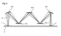
- such a device comprises a radiation source 1 comprising for example at least one light-emitting diode and arranged to emit radiation (R, figure 3 ).
- the device also comprises a radiation detector 2 arranged to detect the radiation emitted by the source 1.
- the detector 2 comprises for example at least one photodiode intended to capture the radiation emitted by the source 1 and transform it into an electrical signal to be processed. .
- the radiation source 1 and the detector 2 are fixed on an electronic card 3 integrated in the device.
- the radiation source and detector are positioned on the map next to each other.
- the device also comprises a closed optical chamber 4, inside which the radiation R is emitted.
- the optical chamber 4, which is the subject of the invention, comprises an input 40 in front of which the radiation source 1 is positioned and an output 41 in front of which is positioned the detector 2 ( figure 2 ).
- the optical chamber 4 comprises reflection means arranged to reflect the radiation R emitted by the source 1 and make it converge towards the detector 2.
- the reflection means comprise a first series of adjacent mirrors Mi and a second series of adjacent mirrors M'i.
- the first series of mirrors Mi and the second series of mirrors M'i are arranged so that the radiation R emitted by the source 1 is reflected and focused alternately by a mirror of the second series and then by a mirror of the first series of following a zigzag-shaped optical path from the radiation source 1 to the detector 2.
- the optical chamber employs bifocal mirrors. Each mirror thus comprises, if one follows the optical path, a first focus located upstream of the mirror and a second focus located downstream of the mirror.
- the process described above continues between mirrors of the first series and mirrors of the second series until the radiation reaches the detector 2.
- the mirrors are thus arranged to advance the radiation inside the optical chamber. from the radiation source 1 to the detector 2.
- the use of bifocals makes it possible to focus the radiation from the source to the detector and thus obtain a device of great sensitivity.
- the bifocals used in the first series and in the second series are ellipsoid truncated revolution type.
- the ellipsoid shape of truncated revolution gives the mirror the property of having two foci, which makes it possible, thanks to the arrangement of the invention, to focus a maximum of the radiation on the detector 2 and to limit the bounces inside the the optical chamber 4.
- the first mirror M'1 of the second series is oriented so as to focus the radiation towards the first mirror M1 of the first series while being in line with the radiation source 1 and having the source of radiation 1 located at his first home.
- the last mirror M'n is located directly above the detector 2 and is oriented so as to focus the radiation coming from the mirror Mn-1 of the first series towards the detector 2, the detector being located at its second focus.
- Each mirror is for example made by depositing a reflective layer on a piece of plastic material.
- the reflective layer is for example a layer of gold deposited by PVD ("Physical Vapor Deposition") or by electrolysis.
- the optical chamber 4 is formed of two distinct parts 42, 43 attached to one another, an upper portion 43 being fixed on a lower portion 42 so as to obtain a closed optical chamber.
- a screw 44 is for example provided for fixing the two parts together.
- the mirrors Mi of the first series are formed in the lower part 42 and the mirrors M'i of the second series are formed in the upper part 43.
- the lower part 42 has a first opening forming said input 40 of the radiation and a second opening forming said output 41 of the radiation R.
- the ellipsoid shape of the mirrors is obtained by molding in the first portion 42 and in the second portion 43 of the optical chamber.
- the radiation produced inside the chamber passes through each time the junction plane of the lower part and the upper part of the chamber.
- the mirrors of the first series and the mirrors of the second series are thus placed in two distinct planes parallel to the joining plane defined above.
- the mirrors Mi, M'i of the first series and of the second series are arranged so that the radiation follows a circular optical path to inside the room. This arrangement makes it possible in particular to obtain an optical path that is as long as possible while limiting the size of the device.
- the optical chamber 4 is fixed directly, by its first part 42, on the electronic card 3 so that the radiation source 1 and the detector 2 is in vis-à-vis respectively of the input 40 of the optical chamber and the output 41 of the optical chamber.
- the device may comprise integrated processing means (not shown) making it possible to analyze the electrical signal obtained at the output of the detector 2 with respect to the signal emitted by the source 1 in order to deduce therefrom the concentration of the gas present in the optical chamber. 3. These processing means may also be independent of the device and separated therefrom.
Abstract
L'invention concerne une chambre optique (4) pour dispositif de détection de gaz qui comporte des moyens de réflexion pour réfléchir un rayonnement (R) issu d'une source de rayonnement (1) et pour le renvoyer vers un détecteur (2) de rayonnement, les moyens de réflexion comportant une première série de miroirs (Mi) adjacents et une deuxième série de miroirs (M'i) adjacents. Les miroirs (Mi) de la première série et les miroirs (M'i) de la deuxième série sont de type ellipsoïde de révolution tronqué. La première série de miroirs et la deuxième série de miroirs sont agencés l'une par rapport à l'autre de sorte que le rayonnement émis par la source de rayonnement (1) soit réfléchi alternativement par un miroir (M'i) de la deuxième série et par un miroir (Mi) de la première série et définisse un trajet optique allant de la source de rayonnement (1) jusqu'au détecteur de rayonnement (2).The invention relates to an optical chamber (4) for a gas detection device which comprises reflection means for reflecting a radiation (R) coming from a radiation source (1) and for sending it back to a detector (2) of radiation, the reflection means comprising a first series of adjacent mirrors (Mi) and a second series of adjacent mirrors (M'i). The mirrors (Mi) of the first series and the mirrors (M'i) of the second series are of ellipsoid type of truncated revolution. The first series of mirrors and the second series of mirrors are arranged relative to one another so that the radiation emitted by the radiation source (1) is reflected alternately by a mirror (M'i) of the second series and mirror (Mi) of the first series and define an optical path from the radiation source (1) to the radiation detector (2).
Description
La présente invention se rapporte à une chambre optique pour dispositif de détection de gaz et au dispositif de détection de gaz intégrant ladite chambre optique. L'invention concerne notamment un dispositif de détection de gaz de type NDIR (pour « Non-Dispersive Infrared »).The present invention relates to an optical chamber for gas detection device and to the gas detection device integrating said optical chamber. The invention relates in particular to an NDIR type gas detection device (for "Non-Dispersive Infrared").
Il est connu du brevet
Une autre solution est décrite dans la demande de brevet
Le but de l'invention est de proposer une chambre optique pour dispositif de détection de gaz permettant au dispositif de disposer d'une sensibilité très satisfaisante, sans augmenter son encombrement. Le dispositif de l'invention incluant ladite chambre optique sera notamment peu sensible aux mouvements relatifs de la source de rayonnement et du détecteur par rapport à la chambre optique.The object of the invention is to provide an optical chamber for gas detection device allowing the device to have a very satisfactory sensitivity, without increasing its size. The device of the invention including said optical chamber will be particularly insensitive to the relative movements of the radiation source and the detector relative to the optical chamber.
Ce but est atteint par une chambre optique pour dispositif de détection de gaz comprenant des moyens de réflexion pour réfléchir un rayonnement issu d'une source de rayonnement et pour le renvoyer vers un détecteur de rayonnement. Les moyens de réflexion comportant une première série de miroirs adjacents et une deuxième série de miroirs adjacents. Les miroirs de la première série et les miroirs de la deuxième série sont à double foyer. La première série de miroirs et la deuxième série de miroirs sont agencés l'une par rapport à l'autre de sorte que le rayonnement émis par la source de rayonnement soit réfléchi alternativement par un miroir de la deuxième série et par un miroir de la première série et définisse un trajet optique allant de la source de rayonnement jusqu'au détecteur de rayonnement.This object is achieved by an optical chamber for a gas detection device comprising reflection means for reflecting radiation from a source of radiation and to send it back to a radiation detector. The reflection means comprising a first series of adjacent mirrors and a second series of adjacent mirrors. The mirrors of the first series and the mirrors of the second series are bifocal. The first series of mirrors and the second series of mirrors are arranged relative to each other so that the radiation emitted by the radiation source is reflected alternately by a mirror of the second series and by a mirror of the first series and defines an optical path from the radiation source to the radiation detector.
Selon l'invention, pour n miroirs dans la deuxième série et n-1 miroirs dans la première série, avec n supérieur ou égal à trois, les miroirs sont agencés de sorte que :
- un miroir M'i de la deuxième série est agencé pour focaliser le rayonnement vers un miroir Mi de la première série, le miroir Mi étant situé au foyer du miroir M'i de la deuxième série, i étant compris entre 1 et n-1,
- un miroir Mi de la première série est agencé pour focaliser le rayonnement vers un miroir M'i+1 de la deuxième série, i étant compris entre 1 et n-1,
- un miroir M'i de la deuxième série, avec i=n, est agencé pour focaliser le rayonnement vers le détecteur,
- un miroir M'i de la deuxième série, avec i=1, est agencé pour recevoir le rayonnement en provenance de la source de rayonnement.
- a mirror M'i of the second series is arranged to focus the radiation towards a mirror Mi of the first series, the mirror Mi being located at the focus of the mirror M'i of the second series, i being between 1 and n-1 ,
- a mirror Mi of the first series is arranged to focus the radiation towards a mirror M'i + 1 of the second series, i being between 1 and n-1,
- a mirror M'i of the second series, with i = n, is arranged to focus the radiation towards the detector,
- a mirror M'i of the second series, with i = 1, is arranged to receive radiation from the radiation source.
Avantageusement, les miroirs de la première série et les miroirs de la deuxième série sont de type ellipsoïde de révolution tronqué.Advantageously, the mirrors of the first series and the mirrors of the second series are of ellipsoidal type of truncated revolution.
Selon une autre particularité, les miroirs sont agencés de sorte que le trajet optique suivi par le rayonnement suive une trajectoire circulaire.According to another feature, the mirrors are arranged so that the optical path followed by the radiation follows a circular path.
Selon une autre particularité, la chambre comporte deux parties fixées l'une sur l'autre, une partie inférieure dans laquelle sont réalisés les miroirs de la première série et une partie supérieure assemblée sur la partie inférieure et dans laquelle sont réalisés les miroirs de la deuxième série.According to another feature, the chamber comprises two parts fixed one on the other, a lower part in which are made the mirrors of the first series and an upper part assembled on the lower part and in which are made the mirrors of the second series.
Selon une autre particularité, les miroirs de la première série et les miroirs de la deuxième série présentent une forme ellipsoïde et chaque forme ellipsoïde est obtenue par moulage dans la première partie et la deuxième partie de la chambre optique.According to another feature, the mirrors of the first series and the mirrors of the second series have an ellipsoidal shape and each ellipsoid shape is obtained by molding in the first part and the second part of the optical chamber.
Selon une autre particularité, chaque miroir comporte une surface réfléchissante réalisée par dépôt d'une couche réfléchissante sur la forme ellipsoïde.According to another feature, each mirror has a reflective surface formed by depositing a reflective layer on the ellipsoid shape.
Selon une autre particularité, la couche réfléchissante est déposée par PVD ou par électrolyse et comporte par exemple de l'or.According to another feature, the reflective layer is deposited by PVD or by electrolysis and comprises for example gold.
Selon une autre particularité, la chambre optique comporte une entrée destinée à être située en vis-à-vis de la source de rayonnement et une sortie destinée à être située en vis-à-vis du détecteur de rayonnement.According to another feature, the optical chamber has an input intended to be located vis-à-vis the radiation source and an output intended to be located vis-à-vis the radiation detector.
L'invention concerne également un dispositif de détection comprenant une source de rayonnement agencée pour émettre un rayonnement, un détecteur de rayonnement et une chambre optique dans laquelle est situé le gaz à analyser et agencée pour transmettre le rayonnement de la source de rayonnement vers le détecteur de rayonnement, la chambre optique étant telle que définie ci-dessus.The invention also relates to a detection device comprising a radiation source arranged to emit radiation, a radiation detector and an optical chamber in which the gas to be analyzed is located and arranged to transmit radiation from the radiation source to the detector. of radiation, the optical chamber being as defined above.
Selon une particularité du dispositif, la source de rayonnement et le détecteur de rayonnement sont agencés l'un à côté de l'autre.According to a feature of the device, the radiation source and the radiation detector are arranged next to each other.
Selon une autre particularité, la source de rayonnement et le détecteur de rayonnement sont fixés sur une même carte électronique.According to another feature, the radiation source and the radiation detector are fixed on the same electronic card.
Selon une autre particularité, la source de rayonnement comporte au moins une diode électroluminescente.According to another feature, the radiation source comprises at least one light emitting diode.
Selon une autre particularité, le détecteur de rayonnement comporte au moins une photodiode.According to another feature, the radiation detector comprises at least one photodiode.
D'autres caractéristiques et avantages vont apparaître dans la description détaillée qui suit faite en regard des dessins annexés dans lesquels :
- la
figure 1 représente, vu en éclaté et en perspective, le dispositif de détection de l'invention, - la
figure 2 représente en perspective la partie basse de la chambre optique du dispositif, - la
figure 3 illustre de manière schématique le principe de fonctionnement du dispositif de l'invention.
- the
figure 1 represents, seen exploded and in perspective, the detection device of the invention, - the
figure 2 represents in perspective the lower part of the optical chamber of the device, - the
figure 3 schematically illustrates the operating principle of the device of the invention.
L'invention concerne une chambre optique pour un dispositif de détection de gaz et le dispositif de détection de gaz correspondant. Le dispositif de détection est destiné à déterminer la concentration d'un gaz, tel que par exemple le dioxyde de carbone.The invention relates to an optical chamber for a gas detection device and the corresponding gas detection device. The detection device is intended to determine the concentration of a gas, such as for example carbon dioxide.
En référence à la
Le dispositif comporte également un détecteur 2 de rayonnement agencé pour détecter le rayonnement émis par la source 1. Le détecteur 2 comporte par exemple au moins une photodiode destinée à capter le rayonnement émis par la source 1 et à le transformer en un signal électrique à traiter.The device also comprises a
Avantageusement, la source de rayonnement 1 et le détecteur 2 sont fixés sur une carte électronique 3, intégrée dans le dispositif.Advantageously, the
Idéalement, la source de rayonnement et le détecteur sont positionnés sur la carte l'un à côté de l'autre.Ideally, the radiation source and detector are positioned on the map next to each other.
Le dispositif comporte également une chambre optique 4 fermée, à l'intérieur de laquelle est émis le rayonnement R. La chambre optique 4, objet de l'invention, comporte une entrée 40 devant laquelle est positionnée la source de rayonnement 1 et une sortie 41 devant laquelle est positionné le détecteur 2 (
La chambre optique 4 comporte des moyens de réflexion agencés pour réfléchir le rayonnement R émis par la source 1 et le faire converger vers le détecteur 2.The
Selon l'invention, les moyens de réflexion comprennent une première série de miroirs Mi adjacents et une deuxième série de miroirs M'i adjacents. La première série de miroirs Mi et la deuxième série de miroirs M'i sont agencées de sorte que le rayonnement R émis par la source 1 soit réfléchi et focalisé alternativement par un miroir de la deuxième série puis par un miroir de la première série de manière à suivre un trajet optique en forme de zigzag de la source de rayonnement 1 jusqu'au détecteur 2. Pour obtenir ce résultat, la chambre optique emploie des miroirs à double foyer. Chaque miroir comporte ainsi, si l'on suit le trajet optique, un premier foyer situé en amont du miroir et un deuxième foyer situé en aval du miroir.According to the invention, the reflection means comprise a first series of adjacent mirrors Mi and a second series of adjacent mirrors M'i. The first series of mirrors Mi and the second series of mirrors M'i are arranged so that the radiation R emitted by the
La
- la source de
rayonnement 1 émet un rayonnement à destination d'un premier miroir M'1 de la deuxième série, la source derayonnement 1 étant située au premier foyer du premier miroir M'1 de la deuxième série. - le premier miroir M'1 de la deuxième série réfléchit le rayonnement R reçu et le focalise à destination d'un premier miroir M1 de la première série situé au deuxième foyer du premier miroir M'1 de la deuxième série.
- le premier miroir M1 de la première série réfléchit le rayonnement R reçu et le focalise vers un deuxième miroir M'2 de la deuxième série, distinct du premier miroir M'1 de la deuxième série et situé au deuxième foyer du premier miroir M1 de la première série (le premier miroir M'1 de la deuxième série occupant le premier foyer du premier miroir M1 de la première série),
- le deuxième miroir M'2 de la deuxième série réfléchit le rayonnement R reçu et le focalise vers un deuxième miroir M2 de la première série, distinct du premier miroir M1 de la première série et situé au deuxième foyer du deuxième miroir M'2 de la deuxième série (le premier miroir M1 de la première série occupant le premier foyer du deuxième miroir M'2 de la deuxième série).
- the
radiation source 1 emits radiation to a first mirror M'1 of the second series, theradiation source 1 being located at the first focus of the first mirror M'1 of the second series. - the first mirror M'1 of the second series reflects the received radiation R and focuses it to a first mirror M1 of the first series located at the second focus of the first mirror M'1 of the second series.
- the first mirror M1 of the first series reflects the received radiation R and focuses it towards a second mirror M'2 of the second series, distinct from the first mirror M'1 of the second series and situated at the second focus of the first mirror M1 of the first series (the first mirror M'1 of the second series occupying the first focus of the first mirror M1 of the first series),
- the second mirror M'2 of the second series reflects the received radiation R and focuses it towards a second mirror M2 of the first series, distinct from the first mirror M1 of the first series and located at the second focus of the second mirror M'2 of the second second series (the first mirror M1 of the first series occupying the first focus of the second mirror M'2 of the second series).
Le processus décrit ci-dessus se poursuit entre miroirs de la première série et miroirs de la deuxième série jusqu'à ce que le rayonnement atteigne le détecteur 2. Les miroirs sont ainsi agencés pour faire progresser le rayonnement à l'intérieur de la chambre optique de la source de rayonnement 1 jusqu'au détecteur 2. L'emploi de miroirs à double foyer permet de focaliser le rayonnement de la source jusqu'au détecteur et d'obtenir ainsi un dispositif d'une grande sensibilité.The process described above continues between mirrors of the first series and mirrors of the second series until the radiation reaches the
D'une manière générale, pour n miroirs dans la deuxième série et n-1 miroirs dans la première série, avec n supérieur ou égal à trois, on peut écrire que :
- un miroir M'i de la deuxième série focalise le rayonnement R vers un miroir Mi de la première série, le miroir Mi étant situé au foyer du miroir M'i de la deuxième série, i étant compris entre 1 et n-1,
- un miroir Mi de la première série focalise le rayonnement R vers un miroir M'i+1 de la deuxième série, i étant compris entre 1 et n-1,
- un miroir M'i de la deuxième série, avec i=n, focalise le rayonnement R vers le détecteur,
- un miroir M'i de la deuxième série, avec i=1, reçoit le rayonnement en provenance de la source de rayonnement.
- a mirror M'i of the second series focuses the radiation R towards a mirror Mi of the first series, the mirror Mi being located at the focus of the mirror M'i of the second series, i being between 1 and n-1,
- a mirror Mi of the first series focuses the radiation R towards a mirror M'i + 1 of the second series, i being between 1 and n-1,
- a mirror M'i of the second series, with i = n, focuses the radiation R towards the detector,
- a mirror M'i of the second series, with i = 1, receives the radiation coming from the radiation source.
Avantageusement, les miroirs à double foyer employés dans la première série et dans la deuxième série sont de type ellipsoïde de révolution tronqué. La forme ellipsoïde de révolution tronquée confère au miroir la propriété de posséder deux foyers, ce qui permet, grâce à l'agencement de l'invention, de focaliser un maximum du rayonnement sur le détecteur 2 et de limiter les rebonds à l'intérieur de la chambre optique 4.Advantageously, the bifocals used in the first series and in the second series are ellipsoid truncated revolution type. The ellipsoid shape of truncated revolution gives the mirror the property of having two foci, which makes it possible, thanks to the arrangement of the invention, to focus a maximum of the radiation on the
Préférentiellement, le premier miroir M'1 de la deuxième série est orienté de manière à focaliser le rayonnement vers le premier miroir M1 de la première série tout en étant à l'aplomb de la source de rayonnement 1 et en ayant la source de rayonnement 1 située à son premier foyer. Préférentiellement, le dernier miroir M'n est situé à l'aplomb du détecteur 2 et est orienté de manière à focaliser le rayonnement provenant du miroir Mn-1 de la première série vers le détecteur 2, le détecteur étant situé à son deuxième foyer.Preferably, the first mirror M'1 of the second series is oriented so as to focus the radiation towards the first mirror M1 of the first series while being in line with the
Chaque miroir est par exemple réalisé par dépôt d'une couche réfléchissante sur une pièce en matériau plastique. La couche réfléchissante est par exemple une couche d'or déposée par PVD (« Physical Vapor Déposition ») ou par électrolyse.Each mirror is for example made by depositing a reflective layer on a piece of plastic material. The reflective layer is for example a layer of gold deposited by PVD ("Physical Vapor Deposition") or by electrolysis.
Avantageusement, la chambre optique 4 est formée de deux parties 42, 43 distinctes rapportées l'une sur l'autre, une partie supérieure 43 venant se fixer sur une partie inférieure 42 de manière à obtenir une chambre optique fermée. Une vis 44 est par exemple prévue pour la fixation des deux parties entre elles. Les miroirs Mi de la première série sont formés dans la partie inférieure 42 et les miroirs M'i de la deuxième série sont formés dans la partie supérieure 43. La partie inférieure 42 comporte une première ouverture formant ladite entrée 40 du rayonnement et une deuxième ouverture formant ladite sortie 41 du rayonnement R. Préférentiellement, la forme ellipsoïde des miroirs est obtenue par moulage dans la première partie 42 et dans la deuxième partie 43 de la chambre optique. Pour aller d'un miroir de la première série vers un miroir de la deuxième série, le rayonnement produit à l'intérieur de la chambre traverse à chaque fois le plan de jonction de la partie inférieure et de la partie supérieure de la chambre. Les miroirs de la première série et les miroirs de la deuxième série sont ainsi placées selon deux plans distincts parallèles au plan de jonction défini ci-dessus.Advantageously, the
Selon l'invention, les miroirs Mi, M'i de la première série et de la deuxième série sont agencés de sorte que le rayonnement suive un trajet optique circulaire à l'intérieur de la chambre. Cet agencement permet notamment d'obtenir un trajet optique le plus long possible tout en limitant l'encombrement du dispositif.According to the invention, the mirrors Mi, M'i of the first series and of the second series are arranged so that the radiation follows a circular optical path to inside the room. This arrangement makes it possible in particular to obtain an optical path that is as long as possible while limiting the size of the device.
Selon l'invention, la chambre optique 4 vient se fixer directement, par sa première partie 42, sur la carte électronique 3 de sorte que la source de rayonnement 1 et le détecteur 2 se trouve en vis-à-vis respectivement de l'entrée 40 de la chambre optique et de la sortie 41 de la chambre optique.According to the invention, the
Le dispositif peut comporter des moyens de traitement (non représentés) intégrés permettant d'analyser le signal électrique obtenu en sortie du détecteur 2 par rapport au signal émis par la source 1 en vue d'en déduire la concentration du gaz présent dans la chambre optique 3. Ces moyens de traitement peuvent également être indépendants du dispositif et séparés de celui-ci.The device may comprise integrated processing means (not shown) making it possible to analyze the electrical signal obtained at the output of the
La solution de l'invention présente ainsi plusieurs avantages listés ci-dessous :
- le dispositif est particulièrement compact, tout en permettant de proposer un trajet optique suffisamment long pour rendre le dispositif précis,
- le signal obtenu en sortie est relativement insensible aux mouvements relatifs de la source et du détecteur par rapport à l'entrée et à la sortie de la chambre optique,
- maitrise du nombre de rebonds subis par le rayonnement, ces rebonds atténuant le signal optique transmis au détecteur,
- faible consommation électrique due notamment à l'emploi d'une diode électroluminescente.
- the device is particularly compact, while providing an optical path long enough to make the device accurate,
- the signal obtained at the output is relatively insensitive to the relative movements of the source and the detector with respect to the input and the output of the optical chamber,
- control of the number of rebounds undergone by the radiation, these rebounds attenuating the optical signal transmitted to the detector,
- low power consumption due in particular to the use of a light emitting diode.
Claims (13)
caractérisée en ce que :
characterized in that
Applications Claiming Priority (2)
| Application Number | Priority Date | Filing Date | Title |
|---|---|---|---|
| FR1455984 | 2014-06-26 | ||
| FR1456055A FR3022999B1 (en) | 2014-06-27 | 2014-06-27 | OPTICAL CHAMBER FOR GAS DETECTION DEVICE |
Publications (1)
| Publication Number | Publication Date |
|---|---|
| EP2960642A1 true EP2960642A1 (en) | 2015-12-30 |
Family
ID=53269416
Family Applications (1)
| Application Number | Title | Priority Date | Filing Date |
|---|---|---|---|
| EP15170983.9A Ceased EP2960642A1 (en) | 2014-06-26 | 2015-06-08 | Optical chamber for a gas detection device |
Country Status (3)
| Country | Link |
|---|---|
| US (1) | US9645073B2 (en) |
| EP (1) | EP2960642A1 (en) |
| CN (1) | CN105223151B (en) |
Families Citing this family (5)
| Publication number | Priority date | Publication date | Assignee | Title |
|---|---|---|---|---|
| FR3069334B1 (en) * | 2017-07-21 | 2019-10-18 | Commissariat A L'energie Atomique Et Aux Energies Alternatives | OPTICAL CAVITY WITH HIGH DYNAMICS |
| GB201812766D0 (en) * | 2018-08-06 | 2018-09-19 | Res & Innovation Uk | Optical multi-pass cells |
| DE102018215587A1 (en) * | 2018-09-13 | 2020-03-19 | Osram Opto Semiconductors Gmbh | RADIO-CONDUCTING CAVITY STRUCTURE, GAS SENSOR AND METHOD FOR PRODUCING THE SAME |
| KR102267044B1 (en) * | 2019-12-11 | 2021-06-18 | 주식회사 태성환경연구소 | Carbon dioxide gas sensor using non-dispersive infrared |
| SE543968C2 (en) * | 2020-02-27 | 2021-10-12 | Senseair Ab | Gas sensor with long absorption path length |
Citations (7)
| Publication number | Priority date | Publication date | Assignee | Title |
|---|---|---|---|---|
| DE4214840A1 (en) * | 1992-05-05 | 1993-11-11 | Draegerwerk Ag | Infrared absorption spectroscopy system or White cell for simultaneous analysis of constituents of fluid - provides wall of measurement cell with mirrors and interference filters behind which are located photodiode detectors. |
| WO1998009152A1 (en) * | 1996-08-28 | 1998-03-05 | Martin Hans Goeran Evald | Gas sensor |
| EP1059708A1 (en) * | 1998-11-10 | 2000-12-13 | Tokyo Denshi Kabushiki Kaisha | Apparatus for photoreaction |
| WO2002063283A1 (en) * | 2001-02-08 | 2002-08-15 | Dynament Limited | Gas sensor |
| US20060227327A1 (en) * | 2005-04-08 | 2006-10-12 | Mcneal Mark P | Absorption spectroscopy apparatus and method |
| EP1987346B1 (en) | 2006-02-06 | 2010-08-11 | Gas Sensing Solutions Limited | Dome gas sensor |
| EP2526404A1 (en) | 2010-01-18 | 2012-11-28 | Gas Sensing Solutions Ltd | Gas sensor with radiation guide |
Family Cites Families (9)
| Publication number | Priority date | Publication date | Assignee | Title |
|---|---|---|---|---|
| DE3830906A1 (en) * | 1988-09-10 | 1990-03-15 | Draegerwerk Ag | MIRROR ARRANGEMENT FOR A RADIATION IN A MULTIPLE REFLECTION MEASURING CELL |
| US5065025A (en) * | 1990-03-02 | 1991-11-12 | Axiom Analytical, Inc. | Gas sample analysis provided by light pipe radiation structure |
| US5515859A (en) * | 1993-08-24 | 1996-05-14 | Colorado Health Care Research Corp. | Myocardial infarction and ischemia detection method and apparatus |
| JP3228080B2 (en) * | 1995-08-07 | 2001-11-12 | 富士電機株式会社 | Multiple reflection sample cell |
| US7034304B2 (en) * | 2003-07-25 | 2006-04-25 | Honeywell International, Inc. | Chamber for gas detector |
| CN1985160A (en) * | 2004-07-22 | 2007-06-20 | 光屋环球解决方案有限公司 | Improved design for particle sensor system |
| JP4895294B2 (en) * | 2007-01-30 | 2012-03-14 | 東京エレクトロン株式会社 | Particle monitor system and substrate processing apparatus |
| CN201681044U (en) * | 2010-03-25 | 2010-12-22 | 友丽系统制造股份有限公司 | Photoelectric type gas sense module and device thereof |
| US8785857B2 (en) * | 2011-09-23 | 2014-07-22 | Msa Technology, Llc | Infrared sensor with multiple sources for gas measurement |
-
2015
- 2015-06-08 EP EP15170983.9A patent/EP2960642A1/en not_active Ceased
- 2015-06-15 US US14/739,103 patent/US9645073B2/en active Active
- 2015-06-26 CN CN201510581542.7A patent/CN105223151B/en active Active
Patent Citations (7)
| Publication number | Priority date | Publication date | Assignee | Title |
|---|---|---|---|---|
| DE4214840A1 (en) * | 1992-05-05 | 1993-11-11 | Draegerwerk Ag | Infrared absorption spectroscopy system or White cell for simultaneous analysis of constituents of fluid - provides wall of measurement cell with mirrors and interference filters behind which are located photodiode detectors. |
| WO1998009152A1 (en) * | 1996-08-28 | 1998-03-05 | Martin Hans Goeran Evald | Gas sensor |
| EP1059708A1 (en) * | 1998-11-10 | 2000-12-13 | Tokyo Denshi Kabushiki Kaisha | Apparatus for photoreaction |
| WO2002063283A1 (en) * | 2001-02-08 | 2002-08-15 | Dynament Limited | Gas sensor |
| US20060227327A1 (en) * | 2005-04-08 | 2006-10-12 | Mcneal Mark P | Absorption spectroscopy apparatus and method |
| EP1987346B1 (en) | 2006-02-06 | 2010-08-11 | Gas Sensing Solutions Limited | Dome gas sensor |
| EP2526404A1 (en) | 2010-01-18 | 2012-11-28 | Gas Sensing Solutions Ltd | Gas sensor with radiation guide |
Also Published As
| Publication number | Publication date |
|---|---|
| CN105223151A (en) | 2016-01-06 |
| US20150377767A1 (en) | 2015-12-31 |
| US9645073B2 (en) | 2017-05-09 |
| CN105223151B (en) | 2019-07-12 |
Similar Documents
| Publication | Publication Date | Title |
|---|---|---|
| EP2960642A1 (en) | Optical chamber for a gas detection device | |
| FR3046851B1 (en) | IMPROVED OPTICAL GUIDE AND OPTICAL SYSTEM | |
| EP2277074B1 (en) | Informative eyeglasses | |
| EP1712940B1 (en) | Uniform illumination apparatus comprising a matrix of laser diodes | |
| FR2995977A1 (en) | LIGHT GUIDE FOR A DEVICE FOR LIGHTING AND / OR SIGNALING A MOTOR VEHICLE | |
| WO2010072362A1 (en) | Improved waveguide and associated spectrometer onboard an automobile | |
| FR2966223A1 (en) | Lighting or signaling device for motor vehicle, has deflection unit directing beams toward common propagation portion, and producing secondary beam, where envelopes of secondary beams cut partially | |
| FR2712985A1 (en) | Colorimetric measuring head, and method for determining the internal color of a non-opaque material. | |
| EP2703852A1 (en) | Light guide sheet with input coupling and dioptre with Fresnel surface | |
| FR3063811A1 (en) | OPTICAL GAS SENSOR | |
| FR3022999A1 (en) | OPTICAL CHAMBER FOR GAS DETECTION DEVICE | |
| FR2828281A1 (en) | Device for analyzing a sample by means of a light beam, where a mirror with a discontinuity allows more light to shine through to the sample analyzer | |
| Avila et al. | High efficiency inexpensive 2-slices image slicers | |
| EP2507655B1 (en) | Optical reflector having semi-reflective blades for a position detection device for a helmet, and helmet comprising such a device | |
| EP1657833B1 (en) | Photoelectric detector | |
| FR2774475A1 (en) | OPTICAL TELEMETRY DEVICE | |
| EP2952951B1 (en) | Detection system | |
| EP3583402A1 (en) | Optical particle detector | |
| JP7264134B2 (en) | Spectroscopic analyzer, optical system, and method | |
| EP3785061B1 (en) | Light-guide for gesture-detecting interface module | |
| CN102608075A (en) | Capillary surface plasmon resonance sensor | |
| KR101109148B1 (en) | Surface plasmon resonance sensor and sensing method using surface plasmon resonance | |
| Moreira et al. | Exchangeable low cost polymer biosensor chip for surface plasmon resonance spectroscopy | |
| EP3563288B1 (en) | Barcode reader | |
| JP6599675B2 (en) | Optical sensor |
Legal Events
| Date | Code | Title | Description |
|---|---|---|---|
| PUAI | Public reference made under article 153(3) epc to a published international application that has entered the european phase |
Free format text: ORIGINAL CODE: 0009012 |
|
| AK | Designated contracting states |
Kind code of ref document: A1 Designated state(s): AL AT BE BG CH CY CZ DE DK EE ES FI FR GB GR HR HU IE IS IT LI LT LU LV MC MK MT NL NO PL PT RO RS SE SI SK SM TR |
|
| AX | Request for extension of the european patent |
Extension state: BA ME |
|
| 17P | Request for examination filed |
Effective date: 20160112 |
|
| RBV | Designated contracting states (corrected) |
Designated state(s): AL AT BE BG CH CY CZ DE DK EE ES FI FR GB GR HR HU IE IS IT LI LT LU LV MC MK MT NL NO PL PT RO RS SE SI SK SM TR |
|
| STAA | Information on the status of an ep patent application or granted ep patent |
Free format text: STATUS: THE APPLICATION HAS BEEN REFUSED |
|
| 18R | Application refused |
Effective date: 20200110 |