EP3191692B1 - Diffusor einer thermischen energiemaschine sowie thermische energiemaschine - Google Patents
Diffusor einer thermischen energiemaschine sowie thermische energiemaschine Download PDFInfo
- Publication number
- EP3191692B1 EP3191692B1 EP15798034.3A EP15798034A EP3191692B1 EP 3191692 B1 EP3191692 B1 EP 3191692B1 EP 15798034 A EP15798034 A EP 15798034A EP 3191692 B1 EP3191692 B1 EP 3191692B1
- Authority
- EP
- European Patent Office
- Prior art keywords
- diffuser
- air guiding
- guiding elements
- outlet
- air
- Prior art date
- Legal status (The legal status is an assumption and is not a legal conclusion. Google has not performed a legal analysis and makes no representation as to the accuracy of the status listed.)
- Active
Links
Images
Classifications
-
- F—MECHANICAL ENGINEERING; LIGHTING; HEATING; WEAPONS; BLASTING
- F01—MACHINES OR ENGINES IN GENERAL; ENGINE PLANTS IN GENERAL; STEAM ENGINES
- F01D—NON-POSITIVE DISPLACEMENT MACHINES OR ENGINES, e.g. STEAM TURBINES
- F01D9/00—Stators
- F01D9/02—Nozzles; Nozzle boxes; Stator blades; Guide conduits, e.g. individual nozzles
-
- F—MECHANICAL ENGINEERING; LIGHTING; HEATING; WEAPONS; BLASTING
- F04—POSITIVE - DISPLACEMENT MACHINES FOR LIQUIDS; PUMPS FOR LIQUIDS OR ELASTIC FLUIDS
- F04D—NON-POSITIVE-DISPLACEMENT PUMPS
- F04D29/00—Details, component parts, or accessories
- F04D29/40—Casings; Connections of working fluid
- F04D29/52—Casings; Connections of working fluid for axial pumps
- F04D29/54—Fluid-guiding means, e.g. diffusers
- F04D29/541—Specially adapted for elastic fluid pumps
- F04D29/542—Bladed diffusers
-
- F—MECHANICAL ENGINEERING; LIGHTING; HEATING; WEAPONS; BLASTING
- F02—COMBUSTION ENGINES; HOT-GAS OR COMBUSTION-PRODUCT ENGINE PLANTS
- F02C—GAS-TURBINE PLANTS; AIR INTAKES FOR JET-PROPULSION PLANTS; CONTROLLING FUEL SUPPLY IN AIR-BREATHING JET-PROPULSION PLANTS
- F02C3/00—Gas-turbine plants characterised by the use of combustion products as the working fluid
- F02C3/14—Gas-turbine plants characterised by the use of combustion products as the working fluid characterised by the arrangement of the combustion chamber in the plant
-
- F—MECHANICAL ENGINEERING; LIGHTING; HEATING; WEAPONS; BLASTING
- F04—POSITIVE - DISPLACEMENT MACHINES FOR LIQUIDS; PUMPS FOR LIQUIDS OR ELASTIC FLUIDS
- F04D—NON-POSITIVE-DISPLACEMENT PUMPS
- F04D29/00—Details, component parts, or accessories
- F04D29/40—Casings; Connections of working fluid
- F04D29/42—Casings; Connections of working fluid for radial or helico-centrifugal pumps
- F04D29/4206—Casings; Connections of working fluid for radial or helico-centrifugal pumps especially adapted for elastic fluid pumps
- F04D29/4226—Fan casings
- F04D29/4246—Fan casings comprising more than one outlet
-
- F—MECHANICAL ENGINEERING; LIGHTING; HEATING; WEAPONS; BLASTING
- F04—POSITIVE - DISPLACEMENT MACHINES FOR LIQUIDS; PUMPS FOR LIQUIDS OR ELASTIC FLUIDS
- F04D—NON-POSITIVE-DISPLACEMENT PUMPS
- F04D29/00—Details, component parts, or accessories
- F04D29/40—Casings; Connections of working fluid
- F04D29/42—Casings; Connections of working fluid for radial or helico-centrifugal pumps
- F04D29/44—Fluid-guiding means, e.g. diffusers
- F04D29/441—Fluid-guiding means, e.g. diffusers especially adapted for elastic fluid pumps
- F04D29/444—Bladed diffusers
-
- F—MECHANICAL ENGINEERING; LIGHTING; HEATING; WEAPONS; BLASTING
- F23—COMBUSTION APPARATUS; COMBUSTION PROCESSES
- F23R—GENERATING COMBUSTION PRODUCTS OF HIGH PRESSURE OR HIGH VELOCITY, e.g. GAS-TURBINE COMBUSTION CHAMBERS
- F23R3/00—Continuous combustion chambers using liquid or gaseous fuel
- F23R3/02—Continuous combustion chambers using liquid or gaseous fuel characterised by the air-flow or gas-flow configuration
- F23R3/04—Air inlet arrangements
-
- F—MECHANICAL ENGINEERING; LIGHTING; HEATING; WEAPONS; BLASTING
- F23—COMBUSTION APPARATUS; COMBUSTION PROCESSES
- F23R—GENERATING COMBUSTION PRODUCTS OF HIGH PRESSURE OR HIGH VELOCITY, e.g. GAS-TURBINE COMBUSTION CHAMBERS
- F23R3/00—Continuous combustion chambers using liquid or gaseous fuel
- F23R3/42—Continuous combustion chambers using liquid or gaseous fuel characterised by the arrangement or form of the flame tubes or combustion chambers
-
- F—MECHANICAL ENGINEERING; LIGHTING; HEATING; WEAPONS; BLASTING
- F04—POSITIVE - DISPLACEMENT MACHINES FOR LIQUIDS; PUMPS FOR LIQUIDS OR ELASTIC FLUIDS
- F04D—NON-POSITIVE-DISPLACEMENT PUMPS
- F04D19/00—Axial-flow pumps
- F04D19/02—Multi-stage pumps
-
- F—MECHANICAL ENGINEERING; LIGHTING; HEATING; WEAPONS; BLASTING
- F05—INDEXING SCHEMES RELATING TO ENGINES OR PUMPS IN VARIOUS SUBCLASSES OF CLASSES F01-F04
- F05D—INDEXING SCHEME FOR ASPECTS RELATING TO NON-POSITIVE-DISPLACEMENT MACHINES OR ENGINES, GAS-TURBINES OR JET-PROPULSION PLANTS
- F05D2220/00—Application
- F05D2220/30—Application in turbines
- F05D2220/32—Application in turbines in gas turbines
-
- F—MECHANICAL ENGINEERING; LIGHTING; HEATING; WEAPONS; BLASTING
- F05—INDEXING SCHEMES RELATING TO ENGINES OR PUMPS IN VARIOUS SUBCLASSES OF CLASSES F01-F04
- F05D—INDEXING SCHEME FOR ASPECTS RELATING TO NON-POSITIVE-DISPLACEMENT MACHINES OR ENGINES, GAS-TURBINES OR JET-PROPULSION PLANTS
- F05D2240/00—Components
- F05D2240/10—Stators
- F05D2240/12—Fluid guiding means, e.g. vanes
-
- F—MECHANICAL ENGINEERING; LIGHTING; HEATING; WEAPONS; BLASTING
- F05—INDEXING SCHEMES RELATING TO ENGINES OR PUMPS IN VARIOUS SUBCLASSES OF CLASSES F01-F04
- F05D—INDEXING SCHEME FOR ASPECTS RELATING TO NON-POSITIVE-DISPLACEMENT MACHINES OR ENGINES, GAS-TURBINES OR JET-PROPULSION PLANTS
- F05D2240/00—Components
- F05D2240/10—Stators
- F05D2240/12—Fluid guiding means, e.g. vanes
- F05D2240/128—Nozzles
-
- F—MECHANICAL ENGINEERING; LIGHTING; HEATING; WEAPONS; BLASTING
- F05—INDEXING SCHEMES RELATING TO ENGINES OR PUMPS IN VARIOUS SUBCLASSES OF CLASSES F01-F04
- F05D—INDEXING SCHEME FOR ASPECTS RELATING TO NON-POSITIVE-DISPLACEMENT MACHINES OR ENGINES, GAS-TURBINES OR JET-PROPULSION PLANTS
- F05D2240/00—Components
- F05D2240/35—Combustors or associated equipment
-
- F—MECHANICAL ENGINEERING; LIGHTING; HEATING; WEAPONS; BLASTING
- F05—INDEXING SCHEMES RELATING TO ENGINES OR PUMPS IN VARIOUS SUBCLASSES OF CLASSES F01-F04
- F05D—INDEXING SCHEME FOR ASPECTS RELATING TO NON-POSITIVE-DISPLACEMENT MACHINES OR ENGINES, GAS-TURBINES OR JET-PROPULSION PLANTS
- F05D2250/00—Geometry
- F05D2250/30—Arrangement of components
- F05D2250/37—Arrangement of components circumferential
-
- F—MECHANICAL ENGINEERING; LIGHTING; HEATING; WEAPONS; BLASTING
- F05—INDEXING SCHEMES RELATING TO ENGINES OR PUMPS IN VARIOUS SUBCLASSES OF CLASSES F01-F04
- F05D—INDEXING SCHEME FOR ASPECTS RELATING TO NON-POSITIVE-DISPLACEMENT MACHINES OR ENGINES, GAS-TURBINES OR JET-PROPULSION PLANTS
- F05D2250/00—Geometry
- F05D2250/50—Inlet or outlet
- F05D2250/52—Outlet
Definitions
- the invention relates to a diffuser of a thermal energy machine, in particular a gas turbine, with a diffuser inlet, with a diffuser outlet and with a plurality of air guiding elements, in which an air mass flow passes through the diffuser inlet into the diffuser, and in which the air mass flow which has entered the diffuser passes out of the diffuser again through the diffuser outlet and thereby flows off by means of the air guide elements as a plurality of air mass partial flows.
- the invention also relates to a thermal energy machine, in particular a gas turbine, with a compressor for compressing an air mass flow flowing along the machine's longitudinal center axis in the axial flow direction, with a diffuser axially downstream of this compressor and with two opposing silo combustion chambers arranged radially further outwards which a diffuser outlet area designed by a housing of the thermal energy machine opens radially into inflow channels leading to the silo combustion chambers in such a way that the air mass flow emerging from the diffuser can flow out into the inflow channels by means of the diffuser outlet area.
- Generic diffusers especially downstream of a compressor of a turbine, are well known from the prior art.
- the aerodynamic properties of these diffusers are essentially influenced by the contours of the inner and outer shell of the diffuser and by air baffles at a diffuser outlet, but also in particular by the guide vane row of the last compressor stage of a compressor arranged downstream.
- An essentially radial flow direction of the air mass flow induces, among other things, a secondary flow with a flow component in the radial direction, which can lead to a critical blockage of the air mass flow within the diffuser and thus also to increased flow losses with regard to the air mass flow. Furthermore, partial flow detachments can occur, which can lead to a sensitive reduction in the delay in the air mass flow at the diffuser and, in this respect, also to a lower static pressure at the diffuser outlet.
- the object of the invention is to overcome the above-mentioned disadvantages in particular and also to increase the aerodynamic efficiency of generic diffusers.
- a diffuser of a thermal energy machine in particular a gas turbine, with a diffuser inlet, with a diffuser outlet and with a large number of air guiding elements, in which an air mass flow passes through the diffuser inlet into the diffuser and in which the diffuser enters the diffuser
- the air mass flow reached through the diffuser outlet passes out of the diffuser again and flows off by means of the air guide elements as a plurality of air mass partial flows adjacent in the circumferential direction, at least two directly adjacent air flow elements being designed in such a way that their components detectable in the circumferential direction have an outflow angle ⁇ n based on the the circumferential surface configured in the circumferential direction of the diffuser outlet are different from one another, with the angle of inclination of the air guide elements selected in relation to the circumferential surface depending on their respective n circumferential position are selected at the diffuser outlet and the outflow angle ⁇ n and / or the angle of inclination of the air guiding elements in relation to a circumferential
- This second component is referred to here as the component of the outflow angle that can be detected in the circumferential direction and, according to the invention, is different for at least two directly adjacent air mass partial flows.
- the outflow angles can even be determined for different radial positions of the diffuser outlet. If, however, different components of the outflow angle of adjacent air guide elements are discussed here, this comparison assumes that the compared outflow angles of the air guide elements in question are determined on the same radius.
- the radius is the radial distance between the longitudinal center axis of the diffuser and the relevant point on the rear edge of the air guiding element.
- the respective air mass partial flows can flow out locally at different circumferential positions of the diffuser outlet with a respective individual swirl, so that the individual air mass partial flows can now be fed to the mouth openings of inflow channels of silo combustion chambers with lower losses.
- those air mass partial flows that have to travel a longer distance to the mouth openings can flow out of the diffuser through appropriately designed air guiding elements with a greater swirl than those air mass partial flows that have to cover a shorter path to the mouth openings. This reduces the flow losses between the diffuser outlet and the mouth areas.
- the number of adjacent air guide elements with different components of the outflow angle that can be detected in the circumferential direction can be different in the present case and essentially also depends on the design of the diffuser or the like.
- the preferred directions of the air mass partial flows generated by the air guiding elements can flow away even more precisely and effectively, in particular at a diffuser outlet area, if the angle of inclination of the air guiding elements with respect to the circumferential surface is selected depending on their respective circumferential position at the diffuser outlet.
- air guiding plates or air guiding elements arranged further away from an orifice of an inflow channel have a different angle of inclination, in particular a more acute angle of inclination, than an air guiding plate or air guiding element arranged closer to such an inflow channel.
- the outflow angle ⁇ n and / or the angle of inclination of the air guiding elements in relation to a peripheral surface formed by an outlet opening of the diffuser outlet are smaller, the further the respective air guiding element is from an opening of an inlet duct of silo combustion chambers or the like is arranged remotely, since this allows the partial outflows to be specified in a more targeted manner.
- the outflow angles a relate to the circumferential surface which is formed by the outlet opening of the diffuser outlet running around in the circumferential direction.
- This peripheral surface is spanned by the curved outlet opening of the diffuser outlet that extends in the circumferential direction of the diffuser.
- thermo energy machine in the context of the invention relates essentially to a turbine and in particular to a gas turbine.
- turbine in this respect, the terms “thermal energy machine” and “turbine” are used synonymously in the present case.
- the two immediately adjacent air guide elements are arranged in the circumferential direction of the diffuser outlet directly next to one another, preferably at the diffuser outlet of the diffuser, or alternatively directly behind the diffuser outlet in a diffuser outlet area of a thermal energy machine or a turbine.
- an air guiding element has a sheet metal body which formulates an outflow angle ⁇ n which is advantageous within the meaning of the invention.
- Such a desired outflow angle ⁇ n can be achieved structurally in a particularly simple manner, for example, by means of an angle of inclination of the sheet metal body or of the respective air guide element suitably selected at the diffuser outlet.
- air guide elements of the same design or identical can advantageously be used, as a result of which inexpensive production can be achieved.
- air guiding elements with differently shaped and directed air guiding surfaces can also be used in order to be able to achieve or reinforce the present effects.
- this complicates the manufacture and assembly of the individual different air guiding elements.
- the number of air guiding elements provided can be selected almost arbitrarily, with the outflow angle and / or the angle of inclination of the air guiding elements, in particular of at least two directly adjacent air guiding elements, being able to be selected depending on the number of air guiding elements arranged at the diffuser outlet.
- the present air guiding elements are arranged next to one another in the circumferential direction of the diffuser outlet and therefore also essentially concentrically around a machine longitudinal center axis of a thermal energy machine or a compressor of the thermal energy machine.
- the term “directly” in the sense of the invention in relation to the air guiding elements describes two air guiding elements arranged directly next to one another, between which no further air guiding elements are arranged.
- the term “indirectly” describes adjacent air guiding elements, between which one or more air guiding elements are arranged.
- the air mass partial flows generated by the large number of air guiding elements can flow away from the diffuser outlet at different outflow angles, whereby all air mass partial flows generated can flow away more advantageously, in particular with more favorable preferred directions, for example in the direction of inflow channels from silo combustion chambers or the like arranged radially further out.
- the outflow angles of the air mass partial flows are specified by the individual air guiding elements in such a way that a more direct flow on the inflow channels takes place in this regard.
- the object of the invention is also achieved by a thermal energy machine, in particular a gas turbine, with a compressor for compressing an air mass flow flowing along the longitudinal center axis of the machine in the axial flow direction, with a diffuser axially downstream of this compressor and with two opposing, radially further outwardly arranged silos.
- Combustion chambers in which a diffuser outlet area designed by a housing of the thermal energy machine opens radially into inflow channels leading to the silo combustion chambers in such a way that the air mass flow exiting the diffuser can flow out into the inflow channels by means of the diffuser outlet area, the thermal energy machine passing through distinguishes the diffuser described here, which can be designed according to one of the combination of features described here.
- the diffuser outlet on the thermal energy machine, in particular on the gas turbine can be designed in such a way that, in particular, the inflow channels of the silo combustion chambers can be flown more directly and in a more defined manner by the air mass partial flows.
- a thermal energy machine or turbine equipped with the present diffuser can thus be operated much more effectively.
- a preferred embodiment variant provides that two directly adjacent air guiding elements are arranged inclined at different angles of inclination with respect to the circumferential surface.
- the air mass partial flows generated by the air guide elements inclined differently with respect to the circumferential surface can flow off more individually.
- the common air guiding element is arranged between the two air guiding elements directly adjacent to this, these air guiding elements being placed next to one another in the circumferential direction of the diffuser outlet.
- the air guiding elements in particular two directly adjacent air guiding elements, generate different outflow angles relative to the circumferential surface which is spanned by the outlet opening of the diffuser outlet that runs essentially concentrically around a machine longitudinal center axis of the diffuser, the outflow directions of the Air mass partial flows are specified individually in order to achieve the effects desired in the context of the invention.
- outflow angle ⁇ n and / or the angle of inclination of adjacent air guiding elements are selected as a function of a flow exit angle of the air mass flow of an upstream compressor, formulated by the last compressor stage.
- any blockage of the air mass flow within the diffuser that may arise due to a residual swirl of the air mass flow emerging from the last compressor stage can advantageously be counteracted by setting the outflow angle ⁇ n and / or the angle of inclination of the air guiding elements as a function of a flow exit angle of the air mass flow of the upstream air mass flow formulated by the last compressor stage Compressor are selected.
- the opposing air guide elements can be arranged offset from one another by 180 ° in the circumferential direction of the diffuser outlet. If necessary, unbalanced loads with regard to two silo combustion chamber devices of a gas turbine can be completely avoided or at least significantly reduced if air guide elements lying opposite one another at the diffuser outlet do not have the same outflow angle ⁇ n or the same inclination angle.
- the air mass flow can be divided up more precisely and thus the combustion at the silo combustion chamber devices can be homogenized.
- the partial air mass flows flowing out of the diffuser outlet can already be pre-sorted, so to speak, so that they can flow through a diffuser outlet area in particular more effectively.
- the one in the Figures 1 and 2 Diffuser 1, shown at least partially, is arranged downstream, that is, behind a compressor (not shown here) of a thermal energy machine or turbine 3 as seen in the axial flow direction 2, the axial flow direction 2 being aligned with the longitudinal center axis 4.
- the turbine 3 in this exemplary embodiment is a gas turbine 5, the turbine 3 or the gas turbine 5 also being characterized by two silo combustion chamber devices (not shown) which are arranged radially further outward and not shown, each with a silo combustion chamber (not shown).
- a diffuser outlet region 10 formed downstream behind the diffuser 1 is at least partially through a housing 11 of the turbine 3, with this diffuser outlet area 10 laterally and with respect to its longitudinal center axis 4 in the radial direction 12 (only shown as an example) radially outward into an opening 13 or 14 of an inflow channel 15 or 16, each of which opens up to leads into the corresponding silo combustion chamber.
- the diffuser shown here is a diagonal ring diffuser.
- Diagonal means that the main flow direction in the diffuser 1 is approximately 45 ° with respect to a longitudinal center axis 4 of the diffuser 1.
- Ring diffuser means that the diffuser outlet area 10 is designed as an annular gap which concentrically surrounds the longitudinal center axis 4 of the diffuser 1.
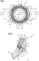
- an air mass flow passes through a diffuser inlet 20 into the diffuser 1, flows through an expanding diffuser channel 21 of the diffuser 1 and then flows on out of a diffuser outlet 22 and the diffuser outlet area 10 to the mouth openings 13 and 14, the outflowing air mass flow in the area of the diffuser outlet 22 by means of a large number of air guiding elements 23 (numbered here only as an example) into a corresponding large number of air mass partial flows 24 (only numbered as an example, see Figure 1 ) is divided.
- the multiplicity of air guiding elements 23 is arranged distributed in the circumferential direction 25 of the diffuser outlet 22 concentrically around the turbine longitudinal center axis 4.
- At least some of the air guiding elements 23 and in particular two immediately adjacent air guiding elements 23 each have an angle of inclination 30 (only exemplary entered) with respect to a circumferential surface 32 spanned by the outlet opening 31 of the diffuser outlet 22 inclined in such a way that the individual air mass partial flows 24 can flow away more directly and more optimally in the direction of the orifices 13 and 14.
- air guiding elements 23 can also be designed differently in such a way that the individual air mass partial flows 24 can flow away more directly and more effectively in the direction of the mouth openings 13 and 14 or even more effectively. So in the embodiment shown according to Figure 1 It can be seen that those air mass partial flows 24 which flow out at the 03:00 o'clock and 09:00 o'clock position of the diffuser 1 do this almost swirl-free. In other words: the air mass partial flows or the air guiding elements 23 guiding them have a rather small or even no component of the outflow angle that can be detected in the circumferential direction. In contrast to this, those air mass partial flows which flow out at the 12 o'clock and 6 o'clock positions of the diffuser are provided with greater swirl. These air mass partial flows or the air guiding elements 23 guiding them therefore have a rather larger component of the outflow angle that can be detected in the circumferential direction.
- two air guiding elements 23 arranged directly adjacent to a jointly adjacent air guiding element 23 are arranged at different inclines to this common, immediately adjacent air guiding element 23, so that preferably each of the air guiding elements 23 with respect to the circumferential surface 32 is arranged inclined differently.
- the air guide elements 23 can generate different outflow angles ⁇ n with respect to the circumferential surface 32 present.
- An outflow angle ⁇ n is thus generated by one of the air guide elements 23, with a first directly adjacent one Air guiding elements 23 produce a different outflow angle ⁇ n + 1 and a further immediately adjacent air directing element 23 produces a different outflow angle ⁇ n-1 . Furthermore, a first, indirectly adjacent air guiding element 23 generates a different outflow angle ⁇ n + 2 , etc.
- angle of inclination 30 of the air guiding elements 23 selected with respect to the circumferential surface 32 is selected as a function of their respective circumferential position 33 at the diffuser outlet 22, whereby the individual air mass partial flows 24 flow even more precisely in the direction of the orifices 13 and 14.
- the air mass partial flows 24 flowing out of the diffuser outlet 22 can already be presorted with regard to their flow direction so well that they can flow away more effectively to the mouth openings 13 and 14.
Landscapes
- Engineering & Computer Science (AREA)
- Mechanical Engineering (AREA)
- General Engineering & Computer Science (AREA)
- Chemical & Material Sciences (AREA)
- Combustion & Propulsion (AREA)
- Structures Of Non-Positive Displacement Pumps (AREA)
Description
- Die Erfindung betrifft einen Diffusor einer thermischen Energiemaschine, insbesondere einer Gasturbine, mit einem Diffusoreintritt, mit einem Diffusoraustritt und mit einer Vielzahl an Luftleitelementen, bei welchem ein Luftmassenstrom durch den Diffusoreintritt hindurch in den Diffusor hinein gelangt, und bei welchem der in den Diffusor gelangte Luftmassenstrom durch den Diffusoraustritt wieder aus dem Diffusor hinaus gelangt und hierbei mittels der Luftleitelemente als eine Vielzahl an Luftmassenpartialströmen abströmt.
- Die Erfindung betrifft des Weiteren eine thermische Energiemaschine, insbesondere eine Gasturbine, mit einem Verdichter zum Verdichten eines entlang der Maschinenlängsmittelachse in axialer Strömungsrichtung strömenden Luftmassenstroms, mit einem diesem Verdichter axial nachgeschalteten Diffusor und mit zwei sich gegenüberliegenden, radial weiter außen angeordneten Silo-Brennkammern, bei welcher ein durch ein Gehäuse der thermischen Energiemaschine ausgestalteter Diffusoraustrittsbereich radial in zu den Silo-Brennkammern hin führenden Zuströmkanäle derart hinein mündet, dass der aus dem Diffusor austretende Luftmassenstrom mittels des Diffusoraustrittsbereichs in die Zuströmkanäle abströmen kann.
- Gattungsgemäße Diffusoren speziell stromab eines Verdichters einer Turbine sind aus dem Stand der Technik hinlänglich bekannt. Die aerodynamischen Eigenschaften dieser Diffusoren werden im Wesentlichen durch die Konturen von Innen- und Außenschale des Diffusors und durch Luftleitbleche an einem Diffusoraustritt, aber auch insbesondere durch die Leitschaufelreihe der letzten Verdichterstufe eines stromab angeordneten Verdichters beeinflusst.
- Durch eine im Wesentlichen radiale Strömungsrichtung des Luftmassenstroms wird unter anderem eine Sekundärströmung mit einer Strömungskomponente in radialer Richtung induziert, welche zu einer kritischen Verblockung des Luftmassenstroms innerhalb des Diffusors und damit auch zu erhöhten Strömungsverlusten bezüglich des Luftmassenstroms führen kann. Ferner kann es zu partiellen Strömungsablösungen kommen, welche zu einer empfindlichen Reduzierung der Verzögerung des Luftmassenstroms am Diffusor und insofern auch zu einem geringeren statischen Druck am Diffusoraustritt führen können.
- Weiter ist es aus der
EP 0 628 728 A1 bekannt, einen so genannten Split-Diffusor zwischen dem Verdichter und einer Ringbrennkammer einer Gasturbine anzuordnen, um die verdichtete Luft einem Brennkammerplenum verlustarm zuzuführen. Dabei sind im Split-Diffusor ausgangsseitig Entdrallschaufeln mit identischen Abströmprofilen angeordnet, wodurch einzelne Luftströme mit gleichem Drall abströmen. Nach derEP 0 651 207 A1 kann die Segmentierung der Abströmung in Umfangsrichtung auch durch individuelle Rechteck-Kanäle erfolgen, deren jeweiligen Austrittsöffnungen auf unterschiedlichen Radien liegen. Gemäß derFR 1 037 610 - Insgesamt eignen sich derartige Diffusoren jedoch nur bedingt zur Verwendung in einer Gasturbine mit Silo-Brennkammern.
- Darüber hinaus offenbart die
US 2007/0271923 A1 eine Gasturbine, bei der zur Reduzierung der Strömungsverluste zwischen Diffusorausgang und Brennkammereingang Leitelemente vorgesehen sind. Deren Befestigung erscheint jedoch recht aufwändig und auch aerodynamisch verlustbehaftet zu seinUS 2011/194931 A1 offenbart die technischen Merkmale vom Oberbegriff vom unabhängigen Anspruch 1. - Es ist Aufgabe der Erfindung, insbesondere die vorstehend genannten Nachteile zu überwinden und zudem die aerodynamische Effizienz von gattungsgemäßen Diffusoren zu steigern.
- Die Aufgabe wird von einem Diffusor einer thermischen Energiemaschine, insbesondere einer Gasturbine, mit einem Diffusoreintritt, mit einem Diffusoraustritt und mit einer Vielzahl an Luftleitelementen gelöst, bei welchem ein Luftmassenstrom durch den Diffusoreintritt hindurch in den Diffusor hinein gelangt, und bei welchem der in den Diffusor gelangte Luftmassenstrom durch den Diffusoraustritt wieder aus dem Diffusor hinaus gelangt und hierbei mittels der Luftleitelemente als eine Vielzahl an in Umfangsrichtung benachbarten Luftmassenpartialströmen abströmt, wobei wenigstens zwei unmittelbar benachbarte Luftleitelemente derart ausgestaltet sind, dass deren in Umfangsrichtung erfassbare Komponente einen Abströmwinkel αn bezogen auf die durch die in Umfangsrichtung umlaufende Austrittsöffnung des Diffusoraustritts ausgestaltete Umfangsfläche voneinander verschieden sind, wobei in Bezug auf die Umfangsfläche gewählte Neigungswinkel der Luftleitelemente in Abhängigkeit von ihrer jeweiligen Umfangslage an dem Diffusoraustritt gewählt sind und wobei die Abströmwinkel αn und/oder die Neigungswinkel der Luftleitelemente in Bezug auf eine durch eine Austrittsöffnung des Diffusoraustritts ausgestaltete Umfangsfläche umso kleiner sind, je weiter das jeweilige Luftleitelement von einer Mündungsöffnung eines Zuströmkanals angeordnet ist.
- Jedem der Luftleitelemente wohnt durch seine Gestalt ein lokaler Abströmwinkel αn inne, mit welchem ein durch das jeweilige Luftleitelement erzeugter Luftmassenpartialstrom von diesem Luftleitelement abströmt. Jeder lokale Abströmwinkel ist in zwei unterschiedliche Komponenten (die wiederum Winkel sind) zerlegbar:
- Eine erste Komponente, welche durch einen Längsschnitt durch den Diffusor entlang seiner Längsmittelachse erfassbar ist, gibt die Neigung der abströmenden Luft gegenüberüber der Längsmittelachse an: ob die Luft parallel zur Längsmittelachse ausströmt oder nach radial weiter außen bzw. innen geleitet wird.
- Eine zweite Komponente des Abströmwinkels, welche durch einen senkrecht zur Längsmittelachse des Diffusors verlaufenden Schnitt erfassbar ist, gibt die Neigung der abströmenden Luft gegenüber der Umfangsrichtung an: ob die Luft parallel zur Umfangsrichtung des Diffusoraustritts (Maximaldrall) oder mit minder starkem Drall um die Längsmittelachse ausströmt. Dabei ist es unerheblich, ob der Drall im Uhrzeigersinn oder entgegengesetzt ist.
- Diese zweite Komponente wird hier als in Umfangsrichtung erfassbare Komponente des Abströmwinkels bezeichnet und ist erfindungsgemäß unterschiedlich für zumindest zwei unmittelbar benachbarte Luftmassenpartialströme. Dies wird damit erreicht, dass die betreffenden Luftleitelemente dementsprechende ausgebildet sind: wenigstens zwei unmittelbar benachbarte Luftleitelemente der Vielzahl an Luftleitelementen sind derart ausgestaltet, dass deren in Umfangsrichtung erfassbare Komponente eines Abströmwinkel αn bezogen auf eine durch die Austrittsöffnung des Diffusoraustritts ausgestaltete Umfangsfläche voneinander verschieden sind.
- Im Detail sind die Abströmwinkel sogar für unterschiedliche radiale Positionen des Diffusoraustritts ermittelbar. Wenn jedoch hier nun von unterschiedlichen Komponenten des Abströmwinkels benachbarter Luftleitelementen die Rede ist, so setzt dieser Vergleich voraus, dass die verglichenen Abströmwinkel der betreffenden Luftleitelemente auf gleichem Radius ermittelt werden. Der Radius ist dabei der radiale Abstand zwischen der Längsmittelachse des Diffusors und dem betreffenden Punkt der Hinterkante des Luftleitelements.
- Bisher sind diese den Luftleitelementen innewohnende Abströmwinkel - bezogen auf die im Sinne der Erfindung formulierte Umfangsfläche - für alle Luftleitelemente gleich, so dass bisher die Luftmassenpartialströmen mit gleichem Drall abströmten, unabhängig davon, an welcher Umfangslage sie platziert waren. Insofern strömten die Luftmassenpartialströme bisher nur undifferenziert von dem Diffusor ab, so dass die meisten der Luftmassenpartialströme beispielsweise Mündungsöffnungen von Zuströmkanälen von Silo-Brennkammern uneffektiv zugeleitet wurden.
- Speziell dieser Nachteil ist vorliegend behoben bzw. zumindest stark abgeschwächt.
- Durch die Verwendung der Erfindung können an unterschiedlichen Umfangspositionen des Diffusoraustritts die jeweiligen Luftmassenpartialströme mit einem jeweils individuellen Drall dort lokal ausströmen, so dass die einzelnen Luftmassenpartialströme den Mündungsöffnungen von Zuströmkanälen von Silo-Brennkammern nun verlustärmer zugeleitet werden können. Beispielsweise können diejenigen Luftmassenpartialströme, die einen längeren Weg zur Mündungsöffnungen zurücklegen müssen, durch entsprechend ausgestaltete Luftleitelemente mit einem größeren Drall aus dem Diffusor ausströmen als diejenigen Luftmassenpartialströme, die einen kürzeren Weg zu den Mündungsöffnungen zurücklegen müssen. Dies verringert die Strömungsverluste zwischen dem Diffusoraustritt und dem Mündungsbereichen.
- Die Anzahl an benachbarten Luftleitelementen mit unterschiedlichen in Umfangsrichtung erfassbaren Komponenten der Abströmwinkel kann vorliegend verschieden sein und hängt im Wesentlichen auch von dem Design des Diffusors oder dergleichen ab.
- Insofern können auch nur ausgewählte Luftleitelemente im Sinne der Erfindung manipuliert werden, um die vorliegenden gewünschten Effekte erzielen zu können.
- Die Vorzugsrichtungen der durch die Luftleitelemente erzeugten Luftmassenpartialströme können noch präziser und effektiver insbesondere an einem Diffusoraustrittsbereich abströmen, wenn in Bezug auf die Umfangsfläche gewählte Neigungswinkel der Luftleitelemente in Abhängigkeit von ihrer jeweiligen Umfangslage an dem Diffusoraustritt gewählt sind. Beispielsweise weisen von einer Mündungsöffnung eines Zuströmkanals weiter entfernt angeordnete Luftleitbleche bzw. Luftleitelemente einen anderen Neigungswinkel, insbesondere einen spitzeren Neigungswinkel, auf als ein näher an einem solchen Zuströmkanal angeordnetes Luftleitblech bzw. Luftleitelement.
- Je nach Ausgestaltung der Erfindung kann es zweckmäßig sein, wenn Abströmwinkel αn und/oder Neigungswinkel der Luftleitelemente in Bezug auf eine durch eine Austrittsöffnung des Diffusoraustritts ausgestaltete Umfangsfläche umso kleiner sind, je weiter das jeweilige Luftleitelement von einer Mündungsöffnung eines Zuströmkanals von Silo-Brennkammern oder dergleichen entfernt angeordnet ist, da hierdurch die partiellen Abströmungen gezielter vorgegeben werden können.
- Im Sinne der Erfindung beziehen sich die Abströmwinkel an auf die Umfangsfläche, welche durch die in Umfangsrichtung umlaufende Austrittsöffnung des Diffusoraustritts ausgestaltet ist.
- Diese Umfangsfläche ist hierbei durch die gebogene und sich in Umfangsrichtung des Diffusors erstreckende Austrittsöffnung des Diffusoraustritts aufgespannt.
- Der Begriff "thermische Energiemaschine" betrifft im Sinne der Erfindung im Wesentlichen eine Turbine und insbesondere eine Gasturbine. Insofern werden die Begriffe "thermische Energiemaschine" und "Turbine" vorliegend synonym verwendet.
- Die zwei unmittelbar benachbarten Luftleitelemente sind hierbei in Umfangsrichtung des Diffusoraustritts direkt nebeneinander bevorzugt an dem Diffusoraustritt des Diffusors, oder alternativ unmittelbar hinter dem Diffusoraustritt in einem Diffusoraustrittsbereich einer thermischen Energiemaschine bzw. einer Turbine angeordnet.
- Es versteht sich, dass die vorliegenden Luftleitelemente unterschiedlich ausgestaltet sein können. Beispielsweise weist ein Luftleitelement einen Blechkörper auf, welcher einen im Sinne der Erfindung vorteilhaften Abströmwinkel αn formuliert.
- Ein solcher gewünschter Abströmwinkel αn kann konstruktiv besonders einfach beispielsweise durch einen am Diffusoraustritt geeignet gewählten Neigungswinkel des Blechkörpers bzw. des jeweiligen Luftleitelements erzielt werden. Hierbei können vorteilhafterweise gleich gestaltete bzw. identische Luftleitelemente verwendet werden, wodurch eine kostengünstige Herstellung erreicht werden kann.
- Kumulativ oder alternativ können auch Luftleitelemente mit unterschiedlich geformten und gerichteten Luftleitflächen verwendet werden, um die vorliegenden Effekte erzielen oder verstärken zu können. Hierdurch verkompliziert sich jedoch die Herstellung und Montage der einzelnen unterschiedlichen Luftleitelemente.
- Vorliegend kann die Anzahl der vorgesehenen Luftleitelemente nahezu beliebig gewählt werden, wobei die Abströmwinkel und/oder die Neigungswinkel der Luftleitelemente, insbesondere von wenigstens zwei unmittelbar benachbarten Luftleitelementen, in Abhängigkeit von der Anzahl der an dem Diffusoraustritt angeordneten Luftleitelemente gewählt sein können.
- Beispielsweise sind 48 solcher Luftleitelemente an dem Umfang des Diffusoraustritts verteilt angeordnet.
- Die vorliegenden Luftleitelemente sind in Umfangsrichtung des Diffusoraustritts nebeneinander und damit auch im Wesentlichen konzentrisch um eine Maschinenlängsmittelachse einer thermischen Energiemaschine bzw. eines Verdichters der thermischen Energiemaschine herum angeordnet.
- An dieser Stelle sei noch erwähnt, dass die Begrifflichkeit "unmittelbar" im Sinne der Erfindung bezogen auf die Luftleitelemente, zwei direkt nebeneinander angeordnete Luftleitelemente beschreibt, zwischen welchen kein weiteres der Luftleitelemente angeordnet ist. Im Gegensatz hierzu beschreibt die Begrifflichkeit "mittelbar" vorliegend benachbarte Luftleitelementen, zwischen denen ein oder mehrere Luftleitelemente angeordnet sind.
- Jedenfalls können die durch die Vielzahl an Luftleitelementen erzeugten Luftmassenpartialströme vorliegend mit unterschiedlichen Abströmwinkeln von dem Diffusoraustritt abströmen, wodurch alle erzeugten Luftmassenpartialströme vorteilhafter, insbesondere mit günstigeren Vorzugsrichtungen, etwa in Richtung von Zuströmkanäle von radial weiter außen angeordneten Silo-Brennkammern oder dergleichen, abströmen können.
- Insbesondere sind die Abströmwinkel der Luftmassenpartialströme derart von den einzelnen Luftleitelementen vorgegeben, dass eine diesbezüglich direktere Anströmung der Zuströmkanäle erfolgt.
- Insofern wird die Aufgabe der Erfindung auch von einer thermischen Energiemaschine, insbesondere einer Gasturbine, mit einem Verdichter zum Verdichten eines entlang der Maschinenlängsmittelachse in axialer Strömungsrichtung strömenden Luftmassenstroms, mit einem diesem Verdichter axial nachgeschalteten Diffusor und mit zwei sich gegenüberliegenden, radial weiter außen angeordneten Silo-Brennkammern gelöst, bei welcher ein durch ein Gehäuse der thermischen Energiemaschine ausgestalteter Diffusoraustrittsbereich radial in zu den Silo-Brennkammern hin führenden Zuströmkanäle derart hinein mündet, dass der aus dem Diffusor austretende Luftmassenstrom mittels des Diffusoraustrittsbereichs in die Zuströmkanäle abströmen kann, wobei die thermische Energiemaschine sich durch den hier beschriebenen Diffusor auszeichnet, welcher nach einer der hier beschriebenen Merkmalskombination ausgestaltet sein kann.
- Hierdurch kann der Diffusoraustritt an der thermischen Energiemaschine, insbesondere an der Gasturbine, derart ausgestaltet werden, dass insbesondere die Zuströmkanäle der Silo-Brennkammern direkter und definierter durch die Luftmassenpartialströme angeströmt werden können.
- Eine durch den vorliegenden Diffusor ausgerüstete thermische Energiemaschine bzw. Turbine kann somit wesentlich effektiver betrieben werden.
- Eine bevorzugte Ausführungsvariante sieht vor, dass zwei unmittelbar benachbarte Luftleitelemente mit unterschiedlichen Neigungswinkeln gegenüber der Umfangsfläche geneigt angeordnet sind.
- Hierdurch können die jeweils durch die unterschiedlich gegenüber der Umfangsfläche geneigten Luftleitelemente erzeugten Luftmassenpartialströme individueller abströmen.
- Gleiches gilt, wenn zwei unmittelbar benachbart zu einem gemeinsam benachbarten Luftleitelement angeordnete Luftleitelemente unterschiedlich stark geneigt gegenüber diesem gemeinsamen unmittelbar benachbarten Luftleitelement angeordnet sind.
- Das gemeinsame Luftleitelement ist hierbei zwischen den beiden hierzu unmittelbar benachbarten Luftleitelementen angeordnet, wobei diese Luftleitelemente in Umfangsrichtung des Diffusoraustritts nebeneinander platziert sind.
- Erzeugen die Luftleitelemente, insbesondere zwei unmittelbar benachbarte Luftleitelemente, relativ zu der Umfangsfläche, welche durch die im Wesentlichen konzentrisch um eine Maschinenlängsmittelachse des Diffusors herum verlaufende Austrittsöffnung des Diffusoraustritts aufgespannt ist, unterschiedliche Abströmwinkel, können die Abströmrichtungen der Luftmassenpartialströme individuell vorgegeben werden, um die im Sinne der Erfindung gewünschten Effekte zu erzielen.
- Darüber hinaus ist es vorteilhaft, wenn Abströmwinkel αn und/oder Neigungswinkel von benachbarten Luftleitelementen, insbesondere von zwei unmittelbar benachbarten Luftleitelementen, in Abhängigkeit von einem von der letzten Verdichterstufe formulierten Strömungsaustrittswinkel des Luftmassenstroms eines stromauf angeordneten Verdichters gewählt sind.
- Einer durch einen Restdrall des aus der letzten Verdichterstufe austretenden Luftmassenstroms gegebenenfalls entstehenden Verblockung des Luftmassenstroms innerhalb des Diffusors kann vorteilhaft dadurch entgegengewirkt werden, dass die Abströmwinkel αn und/oder Neigungswinkel der Luftleitelemente in Abhängigkeit von einem von der letzten Verdichterstufe formulierten Strömungsaustrittswinkel des Luftmassenstroms des vorgeschalteten Verdichters gewählt sind.
- Im Idealfall können die sich gegenüberliegenden Luftleitelemente in Umfangsrichtung des Diffusoraustritts um 180° versetzt zueinander angeordnet sein. Gegebenenfalls können auch Schieflasten hinsichtlich zweier Silo-Brennkammereinrichtungen einer Gasturbine zur Gänze vermieden oder zumindest signifikant reduziert werden, wenn sich am Diffusoraustritt gegenüberliegende Luftleitelemente nicht den gleichen Abströmwinkel αn bzw. nicht den gleichen Neigungswinkel aufweisen.
- Insofern ist es vorteilhaft, wenn sich am Diffusoraustritt gegenüberliegende Luftleitelemente voneinander verschiedene Abströmwinkel αn bzw. voneinander verschiedene Neigungswinkel aufweisen.
- Durch eine individuelle Anpassung der Abströmwinkel αn bzw. der Neigungswinkel im Sinne der Erfindung kann eine Aufteilung des Luftmassenstroms präziser erfolgen und somit eine Homogenisierung der Verbrennung an den Silo-Brennkammereinrichtungen erreicht werden.
- Jedenfalls können mit der vorliegenden Erfindung, die von dem Diffusoraustritt abströmenden Luftmassenpartialströme bereits quasi vorsortiert werden, so dass sie effektiver insbesondere einen Diffusoraustrittsbereich durchströmen können.
- Weitere Merkmale, Effekte und Vorteile vorliegender Erfindung werden anhand anliegender Zeichnung und nachfolgender Beschreibung erläutert, in welchen beispielhaft ein Diffusor mit durch unterschiedlich gewählte Neigungswinkel ausgerichteten Luftleitelementen an einer als Turbine ausgestalteten thermischen Energiemaschine dargestellt und beschrieben ist.
- In der Zeichnung zeigen:
- Figur 1
- schematisch eine quer zu einer Turbinenlängsmittelachse geschnittene Querschnittsansicht eines Diffusors einer Turbine; und
- Figur 2
- schematisch eine perspektivische Teilansicht eines Diffusorsegmentes des in der
Figur 1 gezeigten Diffusors. - Der in den
Figuren 1 und 2 zumindest teilweise gezeigte Diffusor 1 ist stromab, also in axialer Strömungsrichtung 2 gesehen hinter einem hier nicht gezeigten Verdichter einer thermischen Energiemaschine bzw. einer Turbine 3 angeordnet, wobei die axiale Strömungsrichtung 2 mit der Längsmittelachse 4 fluchtet. - Bei der Turbine 3 handelt es sich in diesem Ausführungsbeispiel um eine Gasturbine 5, wobei sich die Turbine 3 bzw. die Gasturbine 5 noch durch zwei radial weiter außen angeordnete und nicht dargestellte Silo-Brennkammereinrichtungen mit jeweils einer Silo-Brennkammer (nicht gezeigt) auszeichnet.
- Hierbei ist ein stromab hinter dem Diffusor 1 ausgebildeter Diffusoraustrittsbereich 10 zumindest teilweise durch ein Gehäuse 11 der Turbine 3 ausgestaltet, wobei dieser Diffusoraustrittsbereich 10 seitlich und in Bezug auf seine Längsmittelachse 4 in radialer Richtung 12 (nur beispielhaft eingezeichnet) radial nach außen in jeweils eine Mündungsöffnung 13 bzw. 14 eines Zuströmkanals 15 bzw. 16 hinein mündet, welcher jeweils bis in die entsprechende Silo-Brennkammer führt.
- Wie aus
Figur 2 ersichtlich, handelt es sich bei dem hier gezeigten Diffusor um einen Diagonal-Ringdiffusor. Diagonal bedeutet dabei, dass die Hauptströmungsrichtung im Diffusor 1 in etwa 45° gegenüber einer Längsmittelachse 4 des Diffusors 1 beträgt. Ringdiffusor bedeutet dabei, dass der Diffusoraustrittsbereich 10 als Ringspalt ausgebildet ist, der die Längsmittelachse 4 des Diffusors 1 konzentrisch umgibt. - Wie insbesondere auch gemäß der Darstellung nach der
Figur 2 gut ersichtlich ist, gelangt ein hier nicht weiter eingezeichneter, den Verdichter in axialer Strömungsrichtung 2 durchströmender Luftmassenstrom durch einen Diffusoreintritt 20 hindurch in den Diffusor 1, durchströmt einen sich aufweitenden Diffusorkanal 21 des Diffusors 1 und strömt anschließend weiter aus einen Diffusoraustritt 22 und dem Diffusoraustrittsbereich 10 zu den Mündungsöffnungen 13 und 14 ab, wobei der abströmende Luftmassenstrom im Bereich des Diffusoraustritts 22 mittels einer Vielzahl an Luftleitelementen 23 (hier nur exemplarisch beziffert) in eine entsprechende Vielzahl an Luftmassenpartialströmen 24 (nur exemplarisch beziffert, sieheFigur 1 ) aufgeteilt wird. - Die Vielzahl an Luftleitelementen 23 ist in Umfangsrichtung 25 des Diffusoraustritts 22 konzentrisch um die Turbinenlängsmittelachse 4 herum verteilt angeordnet.
- Damit die einzelnen Luftmassenpartialströme 24 direkter und optimierter in Richtung der Mündungsöffnungen 13 und 14 abströmen können, sind zumindest einige der Luftleitelemente 23 und insbesondere jeweils zwei unmittelbar benachbarte Luftleitelemente 23 mit einem Neigungswinkel 30 (nur exemplarisch eingetragen) gegenüber einer durch die Austrittsöffnung 31 des Diffusoraustritts 22 aufgespannten Umfangsfläche 32 derart geneigt angeordnet, dass die einzelnen Luftmassenpartialströme 24 direkter und optimierter in Richtung der Mündungsöffnungen 13 und 14 abströmen können.
- Kumulativ oder alternativ können Luftleitelemente 23 noch derart unterschiedlich ausgebildet sein, dass die einzelnen Luftmassenpartialströme 24 direkter und optimierter in Richtung der Mündungsöffnungen 13 und 14 oder noch effektiver abströmen können. So ist im gezeigten Ausführungsbeispiel gemäß
Figur 1 erkennbar, dass diejenigen Luftmassenpartialströme 24, welche auf der 03:00 Uhr und 09:00 Uhr Position des Diffusors 1 ausströmen, dies nahezu drallfrei tun. Mit anderen Worten: Die Luftmassenpartialströme bzw. die diese lenkenden Luftleitelemente 23 weisen eine eher kleine bis gar keine in Umfangsrichtung erfassbare Komponente des Abströmwinkels auf. Im Unterschied dazu sind diejenigen Luftmassenpartialströme, welche auf der 12:00 Uhr und 06:00 Uhr Position des Diffusors ausströmen, mit größerem Drall versehen. Mithin weisen diese Luftmassenpartialströme bzw. die diese lenkenden Luftleitelemente 23 eine eher größere in Umfangsrichtung erfassbare Komponente des Abströmwinkels auf. - Mithin sind in den Übergangsbereichen, beispielsweise bei der 02:00 Uhr Position, zwei unmittelbar benachbart zu einem gemeinsam benachbarten Luftleitelement 23 angeordnete Luftleitelemente 23 unterschiedlich geneigt zu diesem gemeinsamen unmittelbar benachbarten Luftleitelement 23 angeordnet, so dass bevorzugt jedes der Luftleitelemente 23 in Bezug auf die Umfangsfläche 32 anders geneigt angeordnet ist.
- Insofern können die Luftleitelemente 23 bezüglich der vorliegenden Umfangsfläche 32 unterschiedliche Abströmwinkel αn erzeugen.
- Von einem der Luftleitelemente 23 wird also ein Abströmwinkel αn erzeugt, wobei von einem ersten unmittelbar benachbarten Luftleitelemente 23 ein hiervon verschiedener Abströmwinkel αn+1 und von einem weiteren unmittelbar benachbarten Luftleitelemente 23 ein hiervon verschiedener Abströmwinkel αn-1 erzeugt wird. Weiter wird von einem ersten mittelbar benachbarten Luftleitelemente 23 ein hiervon verschiedener Abströmwinkel αn+2 erzeugt usw.
- Ferner sind die in Bezug auf die Umfangsfläche 32 gewählte Neigungswinkel 30 der Luftleitelemente 23 in Abhängigkeit von ihrer jeweiligen Umfangslage 33 an dem Diffusoraustritt 22 gewählt, wodurch die einzelnen Luftmassenpartialströme 24 noch zielgerichteter in Richtung der Mündungsöffnungen 13 und 14 abströmen.
- Mittels des in der Turbine 2 integrierten und vorstehend beschriebenen Diffusors 1 können die von dem Diffusoraustritt 22 abströmenden Luftmassenpartialströme 24 hinsichtlich ihrer Strömungsrichtung bereits derart gut vorsortiert werden, dass sie effektiver zu den Mündungsöffnungen 13 bzw. 14 hin abströmen können.
- Obwohl die Erfindung im Detail durch das bevorzugte Ausführungsbeispiel näher illustriert und beschrieben wurde, so ist die Erfindung nicht durch dieses offenbarte Ausführungsbeispiel eingeschränkt, und andere Variationen können vom Fachmann hieraus abgeleitet werden, ohne den Schutzumfang der Erfindung zu verlassen.
Claims (6)
- Gasturbine (5) umfassend- einen Verdichter zum Verdichten eines entlang der Maschinenlängsmittelachse (4) in axialer Strömungsrichtung (2) strömenden Luftmassenstroms und- einen diesem Verdichter axial nachgeschalteten Diffusor (1), welcher (1) einen Diffusoreintritt (20) und eine Vielzahl an Luftleitelemente (23) und ein durch ein Gehäuse (11) ausgestalteter Diffusoraustrittsbereich (10) mit einem Diffusoraustritt (22) aufweist, wobei ein Luftmassenstrom durch den Diffusoreintritt (20) hindurch in den Diffusor (1) hinein und durch den Diffusoraustritt (22) wieder aus dem Diffusor (1) hinaus gelangt und hierbei mittels der Luftleitelemente (23) als eine Vielzahl an in Umfangsrichtung benachbarten Luftmassenpartialströmen (24) abströmt, weiterhin umfassend- zwei sich gegenüberliegende radial weiter außen angeordnete Silo-Brennkammern und- zwei gegenüberliegende radial zu den Silo-Brennkammern führende Zuströmkanäle (15, 16), wobei der aus dem Diffusor (1) austretende Luftmassenstrom mittels des Diffusoraustrittsbereichs (10) in die Zuströmkanäle (15, 16) abströmen kann,dadurch gekennzeichnet,
dass wenigstens zwei unmittelbar benachbarte Luftleitelemente (23) der Vielzahl an Luftleitelementen (23) derart ausgestaltet sind, dass deren in Umfangsrichtung erfassbare Komponente eines Abströmwinkel αn bezogen auf eine durch die Austrittsöffnung (31) des Diffusoraustritts (22) ausgestaltete Umfangsfläche (32) voneinander verschieden sind, wobei in Bezug auf die Umfangsfläche (32) gewählte Neigungswinkel (30) der Luftleitelemente (23) in Abhängigkeit von ihrer jeweiligen Umfangslage (33) an dem Diffusoraustritt (22) gewählt sind und wobei die Abströmwinkel αn und/oder die Neigungswinkel (30) der Luftleitelemente (23) in Bezug auf eine durch eine Austrittsöffnung (31) des Diffusoraustritts (22) ausgestaltete Umfangsfläche (32) umso kleiner sind, je weiter das jeweilige Luftleitelement (23) von einer Mündungsöffnung (13, 14) des Zuströmkanals (15, 16) angeordnet ist. - Gasturbine (5) nach Anspruch 1,
wobei zwei unmittelbar benachbarte Luftleitelemente (23) mit unterschiedlichen in Umfangsrichtung erfassbaren Neigungswinkeln (30) gegenüber der Umfangsfläche (32) geneigt angeordnet sind. - Gasturbine (5) nach Anspruch 1 oder 2,
wobei zwei unmittelbar benachbart zu einem gemeinsam benachbarten Luftleitelement (23) angeordnete Luftleitelemente (23) unterschiedlich stark geneigt gegenüber diesem gemeinsamen unmittelbar benachbarten Luftleitelement (23) angeordnet sind. - Gasturbine (5) nach einem der Ansprüche 1 bis 3,
wobei Abströmwinkel αn und/oder Neigungswinkel (30) von benachbarten Luftleitelementen (23), insbesondere von zwei unmittelbar benachbarten Luftleitelementen (23), in Abhängigkeit von einem von der letzten Verdichterstufe formulierten Strömungsaustrittswinkel des Luftmassenstroms eines stromauf angeordneten Verdichters gewählt sind. - Gasturbine (5) nach einem der Ansprüche 1 bis 4,
wobei sich am Diffusoraustritt (22) gegenüberliegende Luftleitelemente (23) voneinander verschiedene Abströmwinkel αn bzw. voneinander verschiedene Neigungswinkel (30) aufweisen. - Gasturbine (5) nach einem der Ansprüche 1 bis 5,
wobei der Diffusor (1) als Diagonal-Ringdiffusor ausgestaltet ist.
Applications Claiming Priority (2)
| Application Number | Priority Date | Filing Date | Title |
|---|---|---|---|
| EP14194073.4A EP3023592A1 (de) | 2014-11-20 | 2014-11-20 | Diffusor einer thermischen Energiemaschine sowie thermische Energiemaschine |
| PCT/EP2015/077051 WO2016079221A1 (de) | 2014-11-20 | 2015-11-19 | Diffusor einer thermischen energiemaschine sowie thermische energiemaschine |
Publications (2)
| Publication Number | Publication Date |
|---|---|
| EP3191692A1 EP3191692A1 (de) | 2017-07-19 |
| EP3191692B1 true EP3191692B1 (de) | 2021-02-17 |
Family
ID=52002685
Family Applications (2)
| Application Number | Title | Priority Date | Filing Date |
|---|---|---|---|
| EP14194073.4A Withdrawn EP3023592A1 (de) | 2014-11-20 | 2014-11-20 | Diffusor einer thermischen Energiemaschine sowie thermische Energiemaschine |
| EP15798034.3A Active EP3191692B1 (de) | 2014-11-20 | 2015-11-19 | Diffusor einer thermischen energiemaschine sowie thermische energiemaschine |
Family Applications Before (1)
| Application Number | Title | Priority Date | Filing Date |
|---|---|---|---|
| EP14194073.4A Withdrawn EP3023592A1 (de) | 2014-11-20 | 2014-11-20 | Diffusor einer thermischen Energiemaschine sowie thermische Energiemaschine |
Country Status (3)
| Country | Link |
|---|---|
| US (1) | US10495105B2 (de) |
| EP (2) | EP3023592A1 (de) |
| WO (1) | WO2016079221A1 (de) |
Families Citing this family (2)
| Publication number | Priority date | Publication date | Assignee | Title |
|---|---|---|---|---|
| EP3043056B1 (de) | 2014-12-17 | 2019-07-31 | Pratt & Whitney Canada Corp. | Abgaskanal für einen gasturbinenmotor |
| CN113983494B (zh) * | 2021-09-22 | 2022-10-21 | 南京航空航天大学 | 一种扩压比智能可调的燃气轮机主燃烧室多通道扩压器 |
Citations (1)
| Publication number | Priority date | Publication date | Assignee | Title |
|---|---|---|---|---|
| US20110194931A1 (en) * | 2010-02-05 | 2011-08-11 | Cameron International Corporation | Centrifugal compressor diffuser vanelet |
Family Cites Families (11)
| Publication number | Priority date | Publication date | Assignee | Title |
|---|---|---|---|---|
| GB657366A (en) * | 1948-02-25 | 1951-09-19 | Westinghouse Electric Int Co | Improvements in or relating to fluid pressure apparatus |
| FR1037610A (fr) * | 1950-03-03 | 1953-09-22 | Rolls Royce | Perfectionnements aux ensembles d'aubes de guidage pour conduits annulaires de fluide |
| US4718819A (en) * | 1983-02-25 | 1988-01-12 | Teledyne Industries, Inc. | Variable geometry device for turbine compressor outlet |
| FR2706534B1 (fr) | 1993-06-10 | 1995-07-21 | Snecma | Diffuseur-séparateur multiflux avec redresseur intégré pour turboréacteur. |
| FR2711771B1 (fr) | 1993-10-27 | 1995-12-01 | Snecma | Diffuseur de chambre à alimentation circonférentielle variable. |
| EP1198739B1 (de) * | 1999-07-28 | 2003-04-02 | Siemens Aktiengesellschaft | Diagnoseverfahren und diagnosesystem für eine technische anlage |
| US7234914B2 (en) * | 2002-11-12 | 2007-06-26 | Continum Dynamics, Inc. | Apparatus and method for enhancing lift produced by an airfoil |
| US7097411B2 (en) * | 2004-04-20 | 2006-08-29 | Honeywell International, Inc. | Turbomachine compressor scroll with load-carrying inlet vanes |
| US7600370B2 (en) * | 2006-05-25 | 2009-10-13 | Siemens Energy, Inc. | Fluid flow distributor apparatus for gas turbine engine mid-frame section |
| EP2532898A1 (de) * | 2011-06-08 | 2012-12-12 | Siemens Aktiengesellschaft | Axialturboverdichter |
| US9644496B2 (en) * | 2013-03-13 | 2017-05-09 | General Electric Company | Radial diffuser exhaust system |
-
2014
- 2014-11-20 EP EP14194073.4A patent/EP3023592A1/de not_active Withdrawn
-
2015
- 2015-11-19 WO PCT/EP2015/077051 patent/WO2016079221A1/de not_active Ceased
- 2015-11-19 EP EP15798034.3A patent/EP3191692B1/de active Active
- 2015-11-19 US US15/526,366 patent/US10495105B2/en active Active
Patent Citations (1)
| Publication number | Priority date | Publication date | Assignee | Title |
|---|---|---|---|---|
| US20110194931A1 (en) * | 2010-02-05 | 2011-08-11 | Cameron International Corporation | Centrifugal compressor diffuser vanelet |
Also Published As
| Publication number | Publication date |
|---|---|
| EP3191692A1 (de) | 2017-07-19 |
| US20170314574A1 (en) | 2017-11-02 |
| US10495105B2 (en) | 2019-12-03 |
| WO2016079221A1 (de) | 2016-05-26 |
| EP3023592A1 (de) | 2016-05-25 |
Similar Documents
| Publication | Publication Date | Title |
|---|---|---|
| EP2362065B1 (de) | Nebenstromkanal mit Nachleitschaufelkranz in einem Turbofantriebwerk | |
| EP2577071B1 (de) | Kanal mit strömungsleitfläche | |
| EP2162681B1 (de) | Gasturbinenbrenner | |
| DE102007036527B4 (de) | Düsenanordnung für ein Gasturbinentriebwerk | |
| EP2179143B1 (de) | Spaltkühlung zwischen brennkammerwand und turbinenwand einer gasturbinenanlage | |
| EP2356320B1 (de) | Ringdiffusor für eine axialturbomaschine | |
| DE202017101436U1 (de) | Sanitäre Einsetzeinheit | |
| DE202010016820U1 (de) | Diffusor für einen Ventilator sowie Ventilatoranordnung mit einem derartigen Diffusor | |
| CH702104B1 (de) | Brennstoffdüse mit einer Vorrichtung zum Konditionieren eines Luftstroms durch die Brennstoffdüse. | |
| DE102009040758A1 (de) | Umlenkvorrichtung für einen Leckagestrom in einer Gasturbine und Gasturbine | |
| EP2775131A1 (de) | Schalldämpfer eines Abgasturboladers | |
| EP2716915A1 (de) | Gehäuse für einen Axialventilator | |
| EP2126321A1 (de) | Gasturbine mit einem nachleitkranz und mit einem mischer | |
| DE102007061564A1 (de) | Schaufelblatt mit verbesserter Kühlschlitzanordnung | |
| EP3219918B1 (de) | Gasturbine mit einer kühleinrichtung zur kühlung von plattformen eines leitschaufelkranzes der gasturbine | |
| CH703749A2 (de) | Turbinenabgasraum. | |
| EP3290644B1 (de) | Gasturbine | |
| EP2233836A1 (de) | Drallerzeuger, Verfahren zum Vermeiden von Flammenrückschlag in einem Brenner mit wenigstens einem Drallerzeuger und Brenner | |
| EP2788583B1 (de) | Turbinenleitschaufel mit einem drosselelement | |
| DE102015111746A1 (de) | Gekühltes Turbinenlaufrad, insbesondere für ein Flugtriebwerk | |
| DE112009001754T5 (de) | Abgasdiffusor für Gasturbine | |
| DE102011012039A1 (de) | Kanal mit Strömungsleitfläche | |
| DE102020200447A1 (de) | Gehäuse für einen Ventilator und Ventilator mit einem entsprechenden Gehäuse | |
| WO2016079221A1 (de) | Diffusor einer thermischen energiemaschine sowie thermische energiemaschine | |
| EP3199759A1 (de) | Turbinenschaufel für eine thermische strömungsmaschine |
Legal Events
| Date | Code | Title | Description |
|---|---|---|---|
| STAA | Information on the status of an ep patent application or granted ep patent |
Free format text: STATUS: THE INTERNATIONAL PUBLICATION HAS BEEN MADE |
|
| PUAI | Public reference made under article 153(3) epc to a published international application that has entered the european phase |
Free format text: ORIGINAL CODE: 0009012 |
|
| STAA | Information on the status of an ep patent application or granted ep patent |
Free format text: STATUS: REQUEST FOR EXAMINATION WAS MADE |
|
| 17P | Request for examination filed |
Effective date: 20170412 |
|
| AK | Designated contracting states |
Kind code of ref document: A1 Designated state(s): AL AT BE BG CH CY CZ DE DK EE ES FI FR GB GR HR HU IE IS IT LI LT LU LV MC MK MT NL NO PL PT RO RS SE SI SK SM TR |
|
| AX | Request for extension of the european patent |
Extension state: BA ME |
|
| RAP1 | Party data changed (applicant data changed or rights of an application transferred) |
Owner name: SIEMENS AKTIENGESELLSCHAFT |
|
| RIN1 | Information on inventor provided before grant (corrected) |
Inventor name: MUTKE, STEFAN Inventor name: RECKERT, RAFAEL Inventor name: MUEHL, JULIA Inventor name: WOHLTAT, RENE Inventor name: SPEISER, JULIAN Inventor name: HECKLAU, MARTIN Inventor name: PRUSS, MATTHIAS Inventor name: MAVROMMATIS, PHILIPPOS THEODOROS Inventor name: FUCHS, FLORIAN Inventor name: HERZOG, NILS |
|
| DAV | Request for validation of the european patent (deleted) | ||
| DAX | Request for extension of the european patent (deleted) | ||
| STAA | Information on the status of an ep patent application or granted ep patent |
Free format text: STATUS: EXAMINATION IS IN PROGRESS |
|
| 17Q | First examination report despatched |
Effective date: 20190401 |
|
| GRAP | Despatch of communication of intention to grant a patent |
Free format text: ORIGINAL CODE: EPIDOSNIGR1 |
|
| STAA | Information on the status of an ep patent application or granted ep patent |
Free format text: STATUS: GRANT OF PATENT IS INTENDED |
|
| INTG | Intention to grant announced |
Effective date: 20201020 |
|
| GRAS | Grant fee paid |
Free format text: ORIGINAL CODE: EPIDOSNIGR3 |
|
| GRAA | (expected) grant |
Free format text: ORIGINAL CODE: 0009210 |
|
| STAA | Information on the status of an ep patent application or granted ep patent |
Free format text: STATUS: THE PATENT HAS BEEN GRANTED |
|
| RAP1 | Party data changed (applicant data changed or rights of an application transferred) |
Owner name: SIEMENS ENERGY GLOBAL GMBH & CO. KG |
|
| AK | Designated contracting states |
Kind code of ref document: B1 Designated state(s): AL AT BE BG CH CY CZ DE DK EE ES FI FR GB GR HR HU IE IS IT LI LT LU LV MC MK MT NL NO PL PT RO RS SE SI SK SM TR |
|
| REG | Reference to a national code |
Ref country code: GB Ref legal event code: FG4D Free format text: NOT ENGLISH |
|
| REG | Reference to a national code |
Ref country code: CH Ref legal event code: EP |
|
| REG | Reference to a national code |
Ref country code: DE Ref legal event code: R096 Ref document number: 502015014264 Country of ref document: DE |
|
| REG | Reference to a national code |
Ref country code: AT Ref legal event code: REF Ref document number: 1361735 Country of ref document: AT Kind code of ref document: T Effective date: 20210315 |
|
| REG | Reference to a national code |
Ref country code: IE Ref legal event code: FG4D Free format text: LANGUAGE OF EP DOCUMENT: GERMAN |
|
| REG | Reference to a national code |
Ref country code: CH Ref legal event code: NV Representative=s name: SIEMENS SCHWEIZ AG, CH |
|
| REG | Reference to a national code |
Ref country code: LT Ref legal event code: MG9D |
|
| REG | Reference to a national code |
Ref country code: NL Ref legal event code: MP Effective date: 20210217 |
|
| PG25 | Lapsed in a contracting state [announced via postgrant information from national office to epo] |
Ref country code: PT Free format text: LAPSE BECAUSE OF FAILURE TO SUBMIT A TRANSLATION OF THE DESCRIPTION OR TO PAY THE FEE WITHIN THE PRESCRIBED TIME-LIMIT Effective date: 20210617 Ref country code: NO Free format text: LAPSE BECAUSE OF FAILURE TO SUBMIT A TRANSLATION OF THE DESCRIPTION OR TO PAY THE FEE WITHIN THE PRESCRIBED TIME-LIMIT Effective date: 20210517 Ref country code: LT Free format text: LAPSE BECAUSE OF FAILURE TO SUBMIT A TRANSLATION OF THE DESCRIPTION OR TO PAY THE FEE WITHIN THE PRESCRIBED TIME-LIMIT Effective date: 20210217 Ref country code: HR Free format text: LAPSE BECAUSE OF FAILURE TO SUBMIT A TRANSLATION OF THE DESCRIPTION OR TO PAY THE FEE WITHIN THE PRESCRIBED TIME-LIMIT Effective date: 20210217 Ref country code: FI Free format text: LAPSE BECAUSE OF FAILURE TO SUBMIT A TRANSLATION OF THE DESCRIPTION OR TO PAY THE FEE WITHIN THE PRESCRIBED TIME-LIMIT Effective date: 20210217 Ref country code: GR Free format text: LAPSE BECAUSE OF FAILURE TO SUBMIT A TRANSLATION OF THE DESCRIPTION OR TO PAY THE FEE WITHIN THE PRESCRIBED TIME-LIMIT Effective date: 20210518 Ref country code: BG Free format text: LAPSE BECAUSE OF FAILURE TO SUBMIT A TRANSLATION OF THE DESCRIPTION OR TO PAY THE FEE WITHIN THE PRESCRIBED TIME-LIMIT Effective date: 20210517 |
|
| PG25 | Lapsed in a contracting state [announced via postgrant information from national office to epo] |
Ref country code: SE Free format text: LAPSE BECAUSE OF FAILURE TO SUBMIT A TRANSLATION OF THE DESCRIPTION OR TO PAY THE FEE WITHIN THE PRESCRIBED TIME-LIMIT Effective date: 20210217 Ref country code: PL Free format text: LAPSE BECAUSE OF FAILURE TO SUBMIT A TRANSLATION OF THE DESCRIPTION OR TO PAY THE FEE WITHIN THE PRESCRIBED TIME-LIMIT Effective date: 20210217 Ref country code: RS Free format text: LAPSE BECAUSE OF FAILURE TO SUBMIT A TRANSLATION OF THE DESCRIPTION OR TO PAY THE FEE WITHIN THE PRESCRIBED TIME-LIMIT Effective date: 20210217 Ref country code: LV Free format text: LAPSE BECAUSE OF FAILURE TO SUBMIT A TRANSLATION OF THE DESCRIPTION OR TO PAY THE FEE WITHIN THE PRESCRIBED TIME-LIMIT Effective date: 20210217 Ref country code: NL Free format text: LAPSE BECAUSE OF FAILURE TO SUBMIT A TRANSLATION OF THE DESCRIPTION OR TO PAY THE FEE WITHIN THE PRESCRIBED TIME-LIMIT Effective date: 20210217 |
|
| PG25 | Lapsed in a contracting state [announced via postgrant information from national office to epo] |
Ref country code: IS Free format text: LAPSE BECAUSE OF FAILURE TO SUBMIT A TRANSLATION OF THE DESCRIPTION OR TO PAY THE FEE WITHIN THE PRESCRIBED TIME-LIMIT Effective date: 20210617 |
|
| PG25 | Lapsed in a contracting state [announced via postgrant information from national office to epo] |
Ref country code: EE Free format text: LAPSE BECAUSE OF FAILURE TO SUBMIT A TRANSLATION OF THE DESCRIPTION OR TO PAY THE FEE WITHIN THE PRESCRIBED TIME-LIMIT Effective date: 20210217 Ref country code: CZ Free format text: LAPSE BECAUSE OF FAILURE TO SUBMIT A TRANSLATION OF THE DESCRIPTION OR TO PAY THE FEE WITHIN THE PRESCRIBED TIME-LIMIT Effective date: 20210217 Ref country code: SM Free format text: LAPSE BECAUSE OF FAILURE TO SUBMIT A TRANSLATION OF THE DESCRIPTION OR TO PAY THE FEE WITHIN THE PRESCRIBED TIME-LIMIT Effective date: 20210217 |
|
| REG | Reference to a national code |
Ref country code: DE Ref legal event code: R097 Ref document number: 502015014264 Country of ref document: DE |
|
| PG25 | Lapsed in a contracting state [announced via postgrant information from national office to epo] |
Ref country code: DK Free format text: LAPSE BECAUSE OF FAILURE TO SUBMIT A TRANSLATION OF THE DESCRIPTION OR TO PAY THE FEE WITHIN THE PRESCRIBED TIME-LIMIT Effective date: 20210217 Ref country code: SK Free format text: LAPSE BECAUSE OF FAILURE TO SUBMIT A TRANSLATION OF THE DESCRIPTION OR TO PAY THE FEE WITHIN THE PRESCRIBED TIME-LIMIT Effective date: 20210217 Ref country code: RO Free format text: LAPSE BECAUSE OF FAILURE TO SUBMIT A TRANSLATION OF THE DESCRIPTION OR TO PAY THE FEE WITHIN THE PRESCRIBED TIME-LIMIT Effective date: 20210217 |
|
| PLBE | No opposition filed within time limit |
Free format text: ORIGINAL CODE: 0009261 |
|
| STAA | Information on the status of an ep patent application or granted ep patent |
Free format text: STATUS: NO OPPOSITION FILED WITHIN TIME LIMIT |
|
| 26N | No opposition filed |
Effective date: 20211118 |
|
| PG25 | Lapsed in a contracting state [announced via postgrant information from national office to epo] |
Ref country code: AL Free format text: LAPSE BECAUSE OF FAILURE TO SUBMIT A TRANSLATION OF THE DESCRIPTION OR TO PAY THE FEE WITHIN THE PRESCRIBED TIME-LIMIT Effective date: 20210217 Ref country code: ES Free format text: LAPSE BECAUSE OF FAILURE TO SUBMIT A TRANSLATION OF THE DESCRIPTION OR TO PAY THE FEE WITHIN THE PRESCRIBED TIME-LIMIT Effective date: 20210217 |
|
| PG25 | Lapsed in a contracting state [announced via postgrant information from national office to epo] |
Ref country code: SI Free format text: LAPSE BECAUSE OF FAILURE TO SUBMIT A TRANSLATION OF THE DESCRIPTION OR TO PAY THE FEE WITHIN THE PRESCRIBED TIME-LIMIT Effective date: 20210217 |
|
| PG25 | Lapsed in a contracting state [announced via postgrant information from national office to epo] |
Ref country code: IS Free format text: LAPSE BECAUSE OF FAILURE TO SUBMIT A TRANSLATION OF THE DESCRIPTION OR TO PAY THE FEE WITHIN THE PRESCRIBED TIME-LIMIT Effective date: 20210617 |
|
| PG25 | Lapsed in a contracting state [announced via postgrant information from national office to epo] |
Ref country code: MC Free format text: LAPSE BECAUSE OF FAILURE TO SUBMIT A TRANSLATION OF THE DESCRIPTION OR TO PAY THE FEE WITHIN THE PRESCRIBED TIME-LIMIT Effective date: 20210217 |
|
| GBPC | Gb: european patent ceased through non-payment of renewal fee |
Effective date: 20211119 |
|
| PG25 | Lapsed in a contracting state [announced via postgrant information from national office to epo] |
Ref country code: LU Free format text: LAPSE BECAUSE OF NON-PAYMENT OF DUE FEES Effective date: 20211119 Ref country code: BE Free format text: LAPSE BECAUSE OF NON-PAYMENT OF DUE FEES Effective date: 20211130 |
|
| REG | Reference to a national code |
Ref country code: BE Ref legal event code: MM Effective date: 20211130 |
|
| PG25 | Lapsed in a contracting state [announced via postgrant information from national office to epo] |
Ref country code: IE Free format text: LAPSE BECAUSE OF NON-PAYMENT OF DUE FEES Effective date: 20211119 Ref country code: GB Free format text: LAPSE BECAUSE OF NON-PAYMENT OF DUE FEES Effective date: 20211119 |
|
| PG25 | Lapsed in a contracting state [announced via postgrant information from national office to epo] |
Ref country code: FR Free format text: LAPSE BECAUSE OF NON-PAYMENT OF DUE FEES Effective date: 20211130 |
|
| REG | Reference to a national code |
Ref country code: AT Ref legal event code: MM01 Ref document number: 1361735 Country of ref document: AT Kind code of ref document: T Effective date: 20211119 |
|
| PG25 | Lapsed in a contracting state [announced via postgrant information from national office to epo] |
Ref country code: AT Free format text: LAPSE BECAUSE OF NON-PAYMENT OF DUE FEES Effective date: 20211119 |
|
| PG25 | Lapsed in a contracting state [announced via postgrant information from national office to epo] |
Ref country code: HU Free format text: LAPSE BECAUSE OF FAILURE TO SUBMIT A TRANSLATION OF THE DESCRIPTION OR TO PAY THE FEE WITHIN THE PRESCRIBED TIME-LIMIT; INVALID AB INITIO Effective date: 20151119 |
|
| PG25 | Lapsed in a contracting state [announced via postgrant information from national office to epo] |
Ref country code: CY Free format text: LAPSE BECAUSE OF FAILURE TO SUBMIT A TRANSLATION OF THE DESCRIPTION OR TO PAY THE FEE WITHIN THE PRESCRIBED TIME-LIMIT Effective date: 20210217 |
|
| PG25 | Lapsed in a contracting state [announced via postgrant information from national office to epo] |
Ref country code: MK Free format text: LAPSE BECAUSE OF FAILURE TO SUBMIT A TRANSLATION OF THE DESCRIPTION OR TO PAY THE FEE WITHIN THE PRESCRIBED TIME-LIMIT Effective date: 20210217 |
|
| PG25 | Lapsed in a contracting state [announced via postgrant information from national office to epo] |
Ref country code: MT Free format text: LAPSE BECAUSE OF FAILURE TO SUBMIT A TRANSLATION OF THE DESCRIPTION OR TO PAY THE FEE WITHIN THE PRESCRIBED TIME-LIMIT Effective date: 20210217 |
|
| REG | Reference to a national code |
Ref country code: CH Ref legal event code: U11 Free format text: ST27 STATUS EVENT CODE: U-0-0-U10-U11 (AS PROVIDED BY THE NATIONAL OFFICE) Effective date: 20251201 |
|
| PG25 | Lapsed in a contracting state [announced via postgrant information from national office to epo] |
Ref country code: TR Free format text: LAPSE BECAUSE OF FAILURE TO SUBMIT A TRANSLATION OF THE DESCRIPTION OR TO PAY THE FEE WITHIN THE PRESCRIBED TIME-LIMIT Effective date: 20210217 |
|
| PGFP | Annual fee paid to national office [announced via postgrant information from national office to epo] |
Ref country code: DE Payment date: 20251126 Year of fee payment: 11 |
|
| PGFP | Annual fee paid to national office [announced via postgrant information from national office to epo] |
Ref country code: IT Payment date: 20251121 Year of fee payment: 11 |
|
| PGFP | Annual fee paid to national office [announced via postgrant information from national office to epo] |
Ref country code: CH Payment date: 20251201 Year of fee payment: 11 |