EP3190740A2 - Device and method of handling transmission/reception for serving cell - Google Patents
Device and method of handling transmission/reception for serving cell Download PDFInfo
- Publication number
- EP3190740A2 EP3190740A2 EP17150381.6A EP17150381A EP3190740A2 EP 3190740 A2 EP3190740 A2 EP 3190740A2 EP 17150381 A EP17150381 A EP 17150381A EP 3190740 A2 EP3190740 A2 EP 3190740A2
- Authority
- EP
- European Patent Office
- Prior art keywords
- communication device
- subband
- serving cell
- unit
- network
- Prior art date
- Legal status (The legal status is an assumption and is not a legal conclusion. Google has not performed a legal analysis and makes no representation as to the accuracy of the status listed.)
- Pending
Links
Images


Classifications
-
- H—ELECTRICITY
- H04—ELECTRIC COMMUNICATION TECHNIQUE
- H04L—TRANSMISSION OF DIGITAL INFORMATION, e.g. TELEGRAPHIC COMMUNICATION
- H04L5/00—Arrangements affording multiple use of the transmission path
- H04L5/0001—Arrangements for dividing the transmission path
- H04L5/0003—Two-dimensional division
- H04L5/0005—Time-frequency
- H04L5/0007—Time-frequency the frequencies being orthogonal, e.g. OFDM(A), DMT
- H04L5/001—Time-frequency the frequencies being orthogonal, e.g. OFDM(A), DMT the frequencies being arranged in component carriers
-
- H—ELECTRICITY
- H04—ELECTRIC COMMUNICATION TECHNIQUE
- H04W—WIRELESS COMMUNICATION NETWORKS
- H04W72/00—Local resource management
- H04W72/20—Control channels or signalling for resource management
- H04W72/23—Control channels or signalling for resource management in the downlink direction of a wireless link, i.e. towards a terminal
-
- H—ELECTRICITY
- H04—ELECTRIC COMMUNICATION TECHNIQUE
- H04W—WIRELESS COMMUNICATION NETWORKS
- H04W74/00—Wireless channel access, e.g. scheduled or random access
- H04W74/08—Non-scheduled or contention based access, e.g. random access, ALOHA, CSMA [Carrier Sense Multiple Access]
- H04W74/0808—Non-scheduled or contention based access, e.g. random access, ALOHA, CSMA [Carrier Sense Multiple Access] using carrier sensing, e.g. as in CSMA
- H04W74/0816—Non-scheduled or contention based access, e.g. random access, ALOHA, CSMA [Carrier Sense Multiple Access] using carrier sensing, e.g. as in CSMA carrier sensing with collision avoidance
-
- H—ELECTRICITY
- H04—ELECTRIC COMMUNICATION TECHNIQUE
- H04L—TRANSMISSION OF DIGITAL INFORMATION, e.g. TELEGRAPHIC COMMUNICATION
- H04L25/00—Baseband systems
- H04L25/02—Details ; arrangements for supplying electrical power along data transmission lines
- H04L25/0202—Channel estimation
- H04L25/0224—Channel estimation using sounding signals
- H04L25/0226—Channel estimation using sounding signals sounding signals per se
-
- H—ELECTRICITY
- H04—ELECTRIC COMMUNICATION TECHNIQUE
- H04L—TRANSMISSION OF DIGITAL INFORMATION, e.g. TELEGRAPHIC COMMUNICATION
- H04L5/00—Arrangements affording multiple use of the transmission path
- H04L5/003—Arrangements for allocating sub-channels of the transmission path
- H04L5/0053—Allocation of signaling, i.e. of overhead other than pilot signals
-
- H—ELECTRICITY
- H04—ELECTRIC COMMUNICATION TECHNIQUE
- H04L—TRANSMISSION OF DIGITAL INFORMATION, e.g. TELEGRAPHIC COMMUNICATION
- H04L5/00—Arrangements affording multiple use of the transmission path
- H04L5/0091—Signaling for the administration of the divided path
- H04L5/0092—Indication of how the channel is divided
-
- H—ELECTRICITY
- H04—ELECTRIC COMMUNICATION TECHNIQUE
- H04W—WIRELESS COMMUNICATION NETWORKS
- H04W72/00—Local resource management
- H04W72/04—Wireless resource allocation
- H04W72/044—Wireless resource allocation based on the type of the allocated resource
- H04W72/0453—Resources in frequency domain, e.g. a carrier in FDMA
-
- H—ELECTRICITY
- H04—ELECTRIC COMMUNICATION TECHNIQUE
- H04W—WIRELESS COMMUNICATION NETWORKS
- H04W72/00—Local resource management
- H04W72/20—Control channels or signalling for resource management
- H04W72/21—Control channels or signalling for resource management in the uplink direction of a wireless link, i.e. towards the network
-
- H—ELECTRICITY
- H04—ELECTRIC COMMUNICATION TECHNIQUE
- H04W—WIRELESS COMMUNICATION NETWORKS
- H04W72/00—Local resource management
- H04W72/50—Allocation or scheduling criteria for wireless resources
- H04W72/54—Allocation or scheduling criteria for wireless resources based on quality criteria
- H04W72/542—Allocation or scheduling criteria for wireless resources based on quality criteria using measured or perceived quality
-
- H—ELECTRICITY
- H04—ELECTRIC COMMUNICATION TECHNIQUE
- H04L—TRANSMISSION OF DIGITAL INFORMATION, e.g. TELEGRAPHIC COMMUNICATION
- H04L27/00—Modulated-carrier systems
- H04L27/0006—Assessment of spectral gaps suitable for allocating digitally modulated signals, e.g. for carrier allocation in cognitive radio
-
- H—ELECTRICITY
- H04—ELECTRIC COMMUNICATION TECHNIQUE
- H04L—TRANSMISSION OF DIGITAL INFORMATION, e.g. TELEGRAPHIC COMMUNICATION
- H04L5/00—Arrangements affording multiple use of the transmission path
- H04L5/003—Arrangements for allocating sub-channels of the transmission path
- H04L5/0048—Allocation of pilot signals, i.e. of signals known to the receiver
-
- H—ELECTRICITY
- H04—ELECTRIC COMMUNICATION TECHNIQUE
- H04W—WIRELESS COMMUNICATION NETWORKS
- H04W74/00—Wireless channel access, e.g. scheduled or random access
- H04W74/08—Non-scheduled or contention based access, e.g. random access, ALOHA, CSMA [Carrier Sense Multiple Access]
- H04W74/0808—Non-scheduled or contention based access, e.g. random access, ALOHA, CSMA [Carrier Sense Multiple Access] using carrier sensing, e.g. as in CSMA
-
- H—ELECTRICITY
- H04—ELECTRIC COMMUNICATION TECHNIQUE
- H04W—WIRELESS COMMUNICATION NETWORKS
- H04W88/00—Devices specially adapted for wireless communication networks, e.g. terminals, base stations or access point devices
- H04W88/02—Terminal devices
Definitions
- the present invention relates to a communication device and a method of handling transmission/reception for a serving cell in a wireless communication system.
- the communication device may receive an indication indicating at least one subband unit of a serving cell (e.g., UL licensed serving cell, DL licensed serving cell, UL unlicensed serving cell and/or DL unlicensed serving cell) from a network. Then, the communication device may perform a communication operation in the at least one subband unit with the network, after receiving the indication. That is, subband unit(s) for performing the communication operation is indicated by the network to the communication device.
- the network transmits the indication indicating the at least one subband unit to the communication device, and performs the communication operation in the at least one subband unit with the communication device.
- use of the subband unit(s) for the serving cell is solved according to the process 30.
- Realization of the process 30 is not limited to the above description. The following examples may be applied for realizing the process 30.
- the communication device may perform a LBT in the subband units SU0-SU1, and may perform a measurement in the subband units SU1-SU2 to obtain a measurement result when performing the LBT. Accordingly, the communication device may transmit the measurement result including power status of the subband units SU1-SU2 via the subband unit SU1 to the network according a result of the LBT. As can be seen, a range where the measurement is performed may be different from (but partly overlapped with) a range where the LBT is performed, i.e., a neighboring subband unit is measured. In addition, the communication device may transmit data and/or control information via the subband units SU0-SU1 to the network according the result of the LBT.
- the multiplexing scheme may be a frequency-division multiplexing (FDM) scheme, and the PUCCH may be transmitted in at least one second subband unit of the serving cell. Further, the at least one first subband unit may be adjacent to the at least one second subband unit in a frequency domain.
- the multiplexing scheme may be a time-division multiplexing (TDM) scheme, and the PUSCH may be transmitted in the at least one first subband unit before the PUCCH.
- the multiplexing scheme may be a TDM scheme, and the PUSCH may be transmitted in the at least one first subband unit after the PUCCH.
- the PUCCH may be configured with a PUCCH format.
- the PUCCH format may be a PUCCH format 1, 2 or 3.
- Fig. 6 is a schematic diagram of arrangement of subband units according to an example of the present invention.
- a PUCCH is transmitted in the subband unit SU0, and PUSCHs are transmitted in the subband units SU1-SU3. That is, the PUCCH and the PUSCHs are transmitted according to the FDM scheme.
- the UEs UE1-UE3 may transmit the UCI and the DMRS in corresponding PUCCH regions of the PUCCH with corresponding PUCCH formats. It should be noted that one or more of the subband units SU0-SU3 may not be used for transmitting the corresponding PUSCH and/or the corresponding PUCCH, if a result of a LBT indicates that the one or more of the subband units SU1-SU3 is not clear. That is, the transmission(s) may be performed according to the result of the LBT performed in the subband unit(s).
- Fig. 7 is a schematic diagram of arrangement of subband units according to an example of the present invention.
- PUCCHs of UEs UE0-UE3 configured with various PUCCH formats are transmitted in PUCCHs of the subband units SU0-SU3, respectively. More specifically, the PUCCH and the PUSCHs are transmitted according to the TDM scheme. The PUSCHs are transmitted in the corresponding subband unit before the PUCCHs.
- one or more of the subband units SU0-SU3 may not be used for transmitting the corresponding PUSCH and/or the corresponding PUCCH, if a result of a LBT indicates that the one or more of the subband units SU1-SU3 is not clear. That is, the transmission(s) may be performed according to the result of the LBT performed in the subband unit(s).
- the communication device may transmit a SRS in a first time period of at least one first subband unit of a serving cell (or other time unit such as a time slot or a time interval, etc.) in a time interval to a network.
- the communication device may transmit a PUSCH in a second time period of at least one second subband unit of the serving cell in the time interval to the network, wherein the second time period is after the first time period. That is, the SRS is transmitted before the PUSCH in the same or different subband unit(s) in the time interval.
- Realization of the process 80 is not limited to the above description. The following examples may be applied for realizing the process 80.
- a length of the time interval and a time width of one of the at least one first subband unit are the same. That is, the time interval is a time width of a subband unit.
- the at least one first subband unit and the at least one second subband unit may be overlapped. In another example, the at least one first subband unit and the at least one second subband unit may not be overlapped.
- the communication device may perform a LBT in at least one third subband unit of the serving cell, before transmitting the SRS. Then, the communication device may transmit the SRS to the network according a result of the LBT.
- the at least one third subband unit covers all or part of the at least one first subband unit. That is, the communication device transmits the SRS, if the result of the LBT indicates that the at least one first subband unit is clear. Otherwise, the communication device stops transmitting the SRS.
- a time gap may be between the first time period and the second time period. Further, the time gap may be generated according to a puncturing operation of the SRS. That is, the SRS may be punctured to generate the time gap.
- the SRS may include at least one SRS transmitted in the at least one first subband unit, respectively. That is, in each of the at least one first subband unit, a corresponding SRS (i.e., shortened SRS) is transmitted, to prevent a situation where part of the at least one first subband unit is not used.
- the communication device may transmit a PUCCH in a third time period of at least one third subband unit of the serving cell in the time interval to the network. That is, the SRS, the PUSCH and the PUCCH may be transmitted (i.e., multiplexed) jointly via the serving cell. There are various way of transmitting (i.e., multiplexing) the SRS, the PUSCH and the PUCCH jointly via the serving cell.
- the third time period may be after the second time period.
- the third time period may be before the first time period.
- a length of the third time period may be a sum of a length of the first time period and a length of the second time period.
- a length of the third time period and a length of the second time period may be the same.
- the network receives the PUCCH in the third time period of the at least one third subband unit of the serving cell in the time interval from the communication device.
- a location of the at least one first subband unit and/or a location of the at least one second subband unit may be determined according to a bandwidth of the serving cell, or may be determined according to a higher layer signaling transmitted by the network.
- a bandwidth of the at least one subband unit and/or a bandwidth of the at least one second subband unit may be determined according to the bandwidth of the serving cell, or may be determined according to a higher layer signaling transmitted by the network.
- each of the at least one first subband unit may include a first plurality of PRBs
- the at least one second subband unit may include a second plurality of PRBs.
- one or more of the subband units SU0-SU3 may not be used for transmitting the corresponding SRS and/or the corresponding PUSCH, if a result of a LBT indicates that the one or more of the subband units SU1-SU3 is not clear. That is, the transmission(s) may be performed according to the result of the LBT performed in the subband unit(s).
- Fig. 10 is a schematic diagram of arrangement of subband units according to an example of the present invention.
- Two cases Case 1 and Case 2 are illustrated as follows.
- the communication device transmits a SRS in a time period T1 of one or more of the subband units SU0-SU3 in the subframe to the network.
- the communication device transmits a PUSCH in a time period T2 of one or more of the subband units SU0-SU3 in the subframe to the network.
- the communication device transmits a PUCCH in a time period T3 of one or more of the subband units SU0-SU3 in the subframe to the network.
- the communication device transmits a PUCCH in a time period T1 of one or more of the subband units SU0-SU3 in the subframe to the network.
- the communication device transmits a SRS in a time period T2 of one or more of the subband units SU0-SU3 in the subframe to the network.
- the communication device transmits a PUSCH in a time period T3 of one or more of the subband units SU0-SU3 in the subframe to the network.
- the SRS is transmitted before the PUSCH in the time domain in both cases.
- one or more of the subband units SU0-SU3 may not be used for transmitting the corresponding SRS, the corresponding PUSCH and/or the corresponding PUCCH, if a result of a LBT indicates that the one or more of the subband units SU1-SU3 is not clear. That is, the transmission(s) may be performed according to the result of the LBT performed in the subband unit(s).
- the communication device transmits a SRS in a time period T1 of one or more of the subband units SU1-SU3 in the subframe to the network.
- the communication device transmits a PUSCH in a time period T2 of one or more of the subband units SU1-SU3 in the subframe to the network.
- the communication device transmits a SRS in a time period T1 of one or more of the subband units SU0-SU3 in the subframe to the network.
- the communication device transmits a PUSCH in a time period T2 of one or more of the subband units SU1-SU3 in the subframe to the network.
- Examples of the hardware may include analog circuit(s), digital circuit(s) and/or mixed circuit(s).
- the hardware may include ASIC(s), field programmable gate array(s) (FPGA(s)), programmable logic device(s), coupled hardware components or combination thereof.
- the hardware may include general-purpose processor(s), microprocessor(s), controller(s), digital signal processor(s) (DSP(s)) or combination thereof.
Abstract
Description
- The present invention relates to a communication device and a method of handling transmission/reception for a serving cell in a wireless communication system.
- A long-term evolution (LTE) system supporting the 3rd Generation Partnership Project (3GPP) Rel-8 standard and/or the 3GPP Rel-9 standard are developed by the 3GPP as a successor of the universal mobile telecommunication system (UMTS) for further enhancing performance of the UMTS to satisfy increasing needs of users. The LTE system includes a new radio interface and a new radio network architecture that provides high data rate, low latency, packet optimization, and improved system capacity and coverage. In the LTE system, a radio access network known as an evolved universal terrestrial radio access network (E-UTRAN) includes at least one evolved Node-B (eNB) for communicating with at least one user equipment (UE), and for communicating with a core network including a mobility management entity (MME), a serving gateway, etc., for Non-Access Stratum (NAS) control.
- A LTE-advanced (LTE-A) system, as its name implies, is an evolution of the LTE system. The LTE-A system targets faster switching between power states, improves performance at the coverage edge of an eNB, increases peak data rate and throughput, and includes advanced techniques, such as carrier aggregation (CA), coordinated multipoint (CoMP) transmissions/reception, uplink (UL) multiple-input multiple-output (UL-MIMO), licensed-assisted access (LAA) using LTE, etc. For a UE and an eNB to communicate with each other in the LTE-A system, the UE and the eNB must support standards developed for the LTE-A system, such as the 3GPP Rel-10 standard or later versions.
- Network operators propose to offload network traffic of the LTE/LTE-A system to a serving cell (e.g., licensed serving cell and/or unlicensed serving cell), to ease load of the network traffic. For example, the eNB may provide services to the UE via both a licensed serving cell and an unlicensed serving cell. Alternatively, the services are provided by eNBs to the UE via both the licensed serving cell and the unlicensed serving cell. However, it is difficult for the UE to transmit UL control information to the eNB due to uncertainty of available resource of the unlicensed serving cell of the eNB while a timing requirement of the UL control information should be satisfied. Accordingly, the UL control information may be transmitted to the eNB with an excessive delay. Benefit of the unlicensed serving cell is reduced. Thus, transmission/reception for the serving cell is an important problem to be solved.
- The present invention therefore provides a method and related communication device for handling transmission/reception for a serving cell to solve the abovementioned problem.
- This is achieved by a communication device for handling transmission/reception for a serving cell according to the independent claims here below. The dependent claims pertain to corresponding further developments and improvements.
- As will be seen more clearly from the detailed description following below, the claimed communication device for handling transmission/reception for a serving cell comprises a storage unit for storing instructions and a processing circuit coupled to the storage unit. The processing circuit is configured to execute the instructions stored in the storage unit. The instructions comprise receiving an indication indicating at least one subband unit of a serving cell from a network; and performing a communication operation in the at least one subband unit with the network, after receiving the indication.
-
-
Fig. 1 is a schematic diagram of a wireless communication system according to an example of the present invention. -
Fig. 2 is a schematic diagram of a communication device according to an example of the present invention. -
Fig. 3 is a flowchart of a process according to an example of the present invention. -
Fig. 4 is a schematic diagram of arrangement of subband units according to an example of the present invention. -
Fig. 5 is a flowchart of a process according to an example of the present invention. -
Fig. 6 is a schematic diagram of arrangement of subband units according to an example of the present invention. -
Fig. 7 is a schematic diagram of arrangement of subband units according to an example of the present invention. -
Fig. 8 is a flowchart of aprocess 80 according to an example of the present invention. -
Fig. 9 is a schematic diagram of arrangement of subband units according to an example of the present invention. -
Fig. 10 is a schematic diagram of arrangement of subband units according to an example of the present invention. -
Fig. 11 is a schematic diagram of arrangement of subband units according to an example of the present invention. -
Fig. 12 is a schematic diagram of arrangement of subband units according to an example of the present invention. -
Fig. 1 is a schematic diagram of awireless communication system 10 according to an example of the present invention. Thewireless communication system 10 is briefly composed of a network and a plurality of communication devices. Thewireless communication system 10 may support a time-division duplexing (TDD) mode, a frequency-division duplexing (FDD) mode, a TDD-FDD joint operation mode or a licensed-assisted access (LAA) mode. That is, the network and a communication device may communicate with each other via FDD carrier(s), TDD carrier(s), licensed carrier(s) (licensed serving cell(s)) and/or unlicensed carrier(s) (unlicensed serving cell(s)). In addition, thewireless communication system 10 may support a carrier aggregation (CA). That is, the network and a communication device may communicate with each other via multiple serving cells (e.g., multiple serving carriers) including a primary cell (e.g., primary component carrier) and one or more secondary cells (e.g., secondary component carriers). - In
Fig. 1 , the network and the communication devices are simply utilized for illustrating the structure of thewireless communication system 10. Practically, the network may be a universal terrestrial radio access network (UTRAN) including at least one Node-B (NB) in a universal mobile telecommunications system (UMTS). In another example, the network may be an evolved UTRAN (E-UTRAN) including at least one evolved NB (eNB) and/or at least one relay in a long term evolution (LTE) system, a LTE-Advanced (LTE-A) system or an evolution of the LTE-A system. - Furthermore, the network may also include both the UTRAN/E-UTRAN and a core network, wherein the core network may include network entities such as Mobility Management Entity (MME), Serving Gateway (S-GW), Packet Data Network (PDN) Gateway (P-GW), Self-Organizing Networks (SON) server and/or Radio Network Controller (RNC), etc. In other words, after the network receives information transmitted by a communication device, the information may be processed only by the UTRAN/E-UTRAN and decisions corresponding to the information are made at the UTRAN/E-UTRAN. Alternatively, the UTRAN/E-UTRAN may forward the information to the core network, and the decisions corresponding to the information are made at the core network after the core network processes the information. In addition, the information may be processed by both the UTRAN/E-UTRAN and the core network, and the decisions are made after coordination and/or cooperation are performed by the UTRAN/E-UTRAN and the core network.
- A communication device may be a user equipment (UE), a low cost device (e.g., machine type communication (MTC) device), a device-to-device (D2D) communication device, a mobile phone, a laptop, a tablet computer, an electronic book, a portable computer system, or combination thereof. In addition, the network and the communication device can be seen as a transmitter or a receiver according to direction (i.e., transmission direction), e.g., for an uplink (UL), the communication device is the transmitter and the network is the receiver, and for a downlink (DL), the network is the transmitter and the communication device is the receiver.
-
Fig. 2 is a schematic diagram of acommunication device 20 according to an example of the present invention. Thecommunication device 20 may be a communication device or the network shown inFig. 1 , but is not limited herein. Thecommunication device 20 may include aprocessing circuit 200 such as a microprocessor or Application Specific Integrated Circuit (ASIC), astorage unit 210 and acommunication interfacing unit 220. Thestorage unit 210 may be any data storage device that may store aprogram code 214, accessed and executed by theprocessing circuit 200. Examples of thestorage unit 210 include but are not limited to a subscriber identity module (SIM), read-only memory (ROM), flash memory, random-access memory (RAM), Compact Disc Read-Only Memory (CD-ROM), digital versatile disc-ROM (DVD-ROM), Blu-ray Disc-ROM (BD-ROM), magnetic tape, hard disk, optical data storage device, non-volatile storage unit, non-transitory computer-readable medium (e.g., tangible media), etc. Thecommunication interfacing unit 220 is preferably a transceiver and is used to transmit and receive signals (e.g., data, messages and/or packets) according to processing results of theprocessing circuit 200. -
Fig. 3 is a flowchart of aprocess 30 according to an example of the present invention. Theprocess 30 may be utilized in a communication device shown inFig. 1 , to handle transmission/reception for a serving cell. Theprocess 30 may be compiled into theprogram code 214 and includes the following steps: - Step 300:
- Start.
- Step 302:
- Receive an indication indicating at least one subband unit of a serving cell from a network.
- Step 304:
- Perform a communication operation in the at least one subband unit with the network, after receiving the indication.
- Step 306:
- End.
- According to the
process 30, the communication device may receive an indication indicating at least one subband unit of a serving cell (e.g., UL licensed serving cell, DL licensed serving cell, UL unlicensed serving cell and/or DL unlicensed serving cell) from a network. Then, the communication device may perform a communication operation in the at least one subband unit with the network, after receiving the indication. That is, subband unit(s) for performing the communication operation is indicated by the network to the communication device. Correspondingly, the network transmits the indication indicating the at least one subband unit to the communication device, and performs the communication operation in the at least one subband unit with the communication device. Thus, use of the subband unit(s) for the serving cell is solved according to theprocess 30. - Realization of the
process 30 is not limited to the above description. The following examples may be applied for realizing theprocess 30. - In one example, the communication operation may include a listen before talk (LBT) performed in a first set of the at least one subband unit. Further, the communication device may transmit data and/or control information via the first set of the at least one subband unit to the network according a result of the LBT. For example, the communication device transmits the data and/or the control information, if the result of the LBT indicates that the first set of the at least one subband unit is clear. Otherwise, the communication device stops transmitting the data and/or the control information.
- In one example, the communication operation may include a measurement performed in a second set of the at least one subband unit. Further, the communication device may perform a LBT in a third set of the at least one subband unit, and may transmit a measurement result of the measurement via the third set of the at least one subband unit according to a result of the LBT. For example, the communication device transmits the measurement result, if the result of the LBT indicates that the third set of the at least one subband unit is clear. Otherwise, the communication device stops transmitting the measurement result. In one example, the measurement result may include a LBT successful rate (or failure rate) of the third set of the at least one subband unit. That is, more information is provided to the network, for the network to make a better scheduling decision for the communication device.
- In one example, a location of the at least one subband unit may be determined according to a bandwidth of the serving cell, or may be determined according to a higher layer signaling transmitted by the network. Similarly, a bandwidth of the at least one subband unit may be determined according to the bandwidth of the serving cell, or may be determined according to a higher layer signaling transmitted by the network. In one example, each of the at least one subband unit may include a plurality of physical resource blocks (PRBs).
- It should be noted that, the first set of the at least one subband unit, the second set of the at least one subband unit and/or the third set of the at least one subband unit may be overlapped (e.g., partly overlapped or completely overlapped). For example, the first set of the at least one subband unit and the second set of the at least one subband unit may be the same. In another example, the first set of the at least one subband unit, the second set of the at least one subband unit and the third set of the at least one subband unit may not be overlapped.
-
Fig. 4 is a schematic diagram of arrangement of subband units according to an example of the present invention. There are 4 subband units SU0-SU3 in an unlicensed serving cell, a bandwidth of each of the subband units SU0-SU3 is 20 MHz, and a time width of each of the subband units SU0-SU3 is a subframe (or other time unit such as a time slot or a time interval, etc.). According to the present invention, the communication device receives an indication indicating the subband units SU0-SU2 transmitted by the network. Then, the communication device may perform a communication operation in one or more of the subband units SU0-SU2. For example, the communication device may perform a LBT in the subband units SU0-SU1, and may perform a measurement in the subband units SU1-SU2 to obtain a measurement result when performing the LBT. Accordingly, the communication device may transmit the measurement result including power status of the subband units SU1-SU2 via the subband unit SU1 to the network according a result of the LBT. As can be seen, a range where the measurement is performed may be different from (but partly overlapped with) a range where the LBT is performed, i.e., a neighboring subband unit is measured. In addition, the communication device may transmit data and/or control information via the subband units SU0-SU1 to the network according the result of the LBT. -
Fig. 5 is a flowchart of aprocess 50 according to an example of the present invention. Theprocess 50 may be utilized in a communication device shown inFig. 1 , to handle transmission/reception for a serving cell. Theprocess 50 may be compiled into theprogram code 214 and includes the following steps: - Step 500:
- Start.
- Step 502:
- Transmit a physical UL shared channel (PUSCH) in at least one first subband unit of a serving cell to a network.
- Step 504:
- Transmit a physical UL control channel (PUCCH) accompanied with the PUSCH via the serving cell to the network according to a multiplexing scheme.
- Step 506:
- End.
- According to the
process 50, the communication device may transmit a PUSCH in at least one first subband unit of a serving cell (e.g., UL licensed serving cell, DL licensed serving cell, UL unlicensed serving cell and/or DL unlicensed serving cell) to a network. Then, the communication device may transmit a PUCCH accompanied with the PUSCH via the serving cell to the network according to a multiplexing scheme. That is, the PUSCH and the PUCCH are multiplexed in the at least one subband unit, and are transmitted jointly to the network. In other words, a method for transmitting the PUSCH and the PUCCH is provided for the serving cell. Thus, the problem of transmitting the UL control information (UCI) via the serving cell is solved. - Realization of the
process 50 is not limited to the above description. The following examples may be applied for realizing theprocess 50. - In one example, the multiplexing scheme may be a frequency-division multiplexing (FDM) scheme, and the PUCCH may be transmitted in at least one second subband unit of the serving cell. Further, the at least one first subband unit may be adjacent to the at least one second subband unit in a frequency domain. In one example, the multiplexing scheme may be a time-division multiplexing (TDM) scheme, and the PUSCH may be transmitted in the at least one first subband unit before the PUCCH. In one example, the multiplexing scheme may be a TDM scheme, and the PUSCH may be transmitted in the at least one first subband unit after the PUCCH. In one example, the PUCCH may be configured with a PUCCH format. For example, the PUCCH format may be a
PUCCH format - In one example, a location of the at least one first subband unit (or the at least one second subband unit) may be determined according to a bandwidth of the serving cell, or may be determined according to a higher layer signaling transmitted by the network. Similarly, a bandwidth of the at least one first subband unit (or the at least one second subband unit) may be determined according to the bandwidth of the serving cell, or may be determined according to a higher layer signaling transmitted by the network. In one example, each of the at least one first subband unit (or the at least one second subband unit) may include a plurality of PRBs.
-
Fig. 6 is a schematic diagram of arrangement of subband units according to an example of the present invention. There are 4 subband units SU0-SU3 in an unlicensed serving cell, a bandwidth of each of the subband units SU0-SU3 is 20 MHz, and a time width of each of the subband units SU0-SU3 is a subframe (or other time unit such as a time slot or a time interval, etc.). A PUCCH is transmitted in the subband unit SU0, and PUSCHs are transmitted in the subband units SU1-SU3. That is, the PUCCH and the PUSCHs are transmitted according to the FDM scheme. PUCCH regions of UEs UE0-UE3 configured with various PUCCH formats are multiplexed in the PUCCH according the TDM scheme. In another example, the FDM scheme and/or a code-division multiplexing (CDM) scheme may be used for multiplexing the PUCCH regions of the UEs UE0-UE3. The PUCCH may be termed as a long duration PUCCH, when the FDM scheme is used. As shown inFig. 6 , the UE UE0 may transmit the UCI and a demodulation reference signal (DMRS) in a PUCCH region of the PUCCH with a PUCCH format. The PUCCH may be termed as a short duration PUCCH in this situation. Similarly, the UEs UE1-UE3 may transmit the UCI and the DMRS in corresponding PUCCH regions of the PUCCH with corresponding PUCCH formats. It should be noted that one or more of the subband units SU0-SU3 may not be used for transmitting the corresponding PUSCH and/or the corresponding PUCCH, if a result of a LBT indicates that the one or more of the subband units SU1-SU3 is not clear. That is, the transmission(s) may be performed according to the result of the LBT performed in the subband unit(s). -
Fig. 7 is a schematic diagram of arrangement of subband units according to an example of the present invention. There are 4 subband units SU0-SU3 in an unlicensed serving cell, a bandwidth of each of the subband units SU0-SU3 is 20 MHz, and a time width of each of the subband units SU0-SU3 is a subframe (or other time unit such as a time slot or a time interval, etc.). PUCCHs of UEs UE0-UE3 configured with various PUCCH formats are transmitted in PUCCHs of the subband units SU0-SU3, respectively. More specifically, the PUCCH and the PUSCHs are transmitted according to the TDM scheme. The PUSCHs are transmitted in the corresponding subband unit before the PUCCHs. As shown inFig. 7 , the UE UE1 may transmit the UCI and a DMRS in a PUCCH region of the PUCCH with a PUCCH format. Similarly, the UEs UE0 and the UEs UE2-UE3 may transmit the UCI and the DMRS in corresponding PUCCHs with corresponding PUCCH formats. The present example can be applied to the case where each PUSCH is transmitted in a corresponding subband unit after a corresponding PUCCH. The UCIs of multiple UEs may be transmitted in a PUCCH, when a CDM scheme is used. It should be noted that one or more of the subband units SU0-SU3 may not be used for transmitting the corresponding PUSCH and/or the corresponding PUCCH, if a result of a LBT indicates that the one or more of the subband units SU1-SU3 is not clear. That is, the transmission(s) may be performed according to the result of the LBT performed in the subband unit(s). -
Fig. 8 is a flowchart of aprocess 80 according to an example of the present invention. Theprocess 80 may be utilized in a communication device shown inFig. 1 , to handle transmission/reception for a serving cell. Theprocess 80 may be compiled into theprogram code 214 and includes the following steps: - Step 800:
- Start.
- Step 802:
- Transmit a sounding reference signal (SRS) in a first time period of at least one first subband unit of a serving cell in a time interval to a network.
- Step 804:
- Transmit a PUSCH in a second time period of at least one second subband unit of the serving cell in the time interval to the network, wherein the second time period is after the first time period.
- Step 806:
- End.
- According to the
process 80, the communication device may transmit a SRS in a first time period of at least one first subband unit of a serving cell (or other time unit such as a time slot or a time interval, etc.) in a time interval to a network. In addition, the communication device may transmit a PUSCH in a second time period of at least one second subband unit of the serving cell in the time interval to the network, wherein the second time period is after the first time period. That is, the SRS is transmitted before the PUSCH in the same or different subband unit(s) in the time interval. Correspondingly, the network receives the SRS in the first time period of the at least one first subband unit of the serving cell in the time interval from the communication device, and receives the PUSCH in the second time period of the at least one second subband unit of the serving cell in the time interval from the communication device. Thus, the problem of the transmission of the SRS and the PUSCH via the serving cell is solved. - Realization of the
process 80 is not limited to the above description. The following examples may be applied for realizing theprocess 80. - In one example, a length of the time interval and a time width of one of the at least one first subband unit are the same. That is, the time interval is a time width of a subband unit. In one example, the at least one first subband unit and the at least one second subband unit may be overlapped. In another example, the at least one first subband unit and the at least one second subband unit may not be overlapped. In one example, the communication device may perform a LBT in at least one third subband unit of the serving cell, before transmitting the SRS. Then, the communication device may transmit the SRS to the network according a result of the LBT. Preferably, the at least one third subband unit covers all or part of the at least one first subband unit. That is, the communication device transmits the SRS, if the result of the LBT indicates that the at least one first subband unit is clear. Otherwise, the communication device stops transmitting the SRS.
- In one example, a time gap may be between the first time period and the second time period. Further, the time gap may be generated according to a puncturing operation of the SRS. That is, the SRS may be punctured to generate the time gap. In one example, the SRS may include at least one SRS transmitted in the at least one first subband unit, respectively. That is, in each of the at least one first subband unit, a corresponding SRS (i.e., shortened SRS) is transmitted, to prevent a situation where part of the at least one first subband unit is not used.
- In one example, the communication device may transmit a PUCCH in a third time period of at least one third subband unit of the serving cell in the time interval to the network. That is, the SRS, the PUSCH and the PUCCH may be transmitted (i.e., multiplexed) jointly via the serving cell. There are various way of transmitting (i.e., multiplexing) the SRS, the PUSCH and the PUCCH jointly via the serving cell. For example, the third time period may be after the second time period. In one example, the third time period may be before the first time period. In one example, a length of the third time period may be a sum of a length of the first time period and a length of the second time period. In one example, a length of the third time period and a length of the second time period may be the same. Correspondingly, the network receives the PUCCH in the third time period of the at least one third subband unit of the serving cell in the time interval from the communication device.
- In one example, a location of the at least one first subband unit and/or a location of the at least one second subband unit may be determined according to a bandwidth of the serving cell, or may be determined according to a higher layer signaling transmitted by the network. Similarly, a bandwidth of the at least one subband unit and/or a bandwidth of the at least one second subband unit may be determined according to the bandwidth of the serving cell, or may be determined according to a higher layer signaling transmitted by the network. In one example, each of the at least one first subband unit may include a first plurality of PRBs, and/or the at least one second subband unit may include a second plurality of PRBs.
-
Fig. 9 is a schematic diagram of arrangement of subband units according to an example of the present invention. There are 4 subband units SU0-SU3 in an unlicensed serving cell, a bandwidth of each of the subband units SU0-SU3 is 20 MHz, and a time width of each of the subband units SU0-SU3 is a subframe (or other time unit such as a time slot or a time interval, etc.). Twocases Case 1 andCase 2 are illustrated as follows. InCase 1, the communication device transmits a SRS in a time period T1 of the subband units SU1-SU3 in the subframe to the network. In addition, the communication device transmits a PUSCH in a time period T2 of the subband unit SU2 in the subframe to the network, wherein the time period T2 is after the time period T1. InCase 1, the subband units for transmitting the SRS and the subband unit for transmitting the PUSCH are overlapped.Case 2 is similar toCase 1 except that the SRS is transmitted in the time period T1 of the subband units SU0-SU1. That is, the subband units for transmitting the SRS and the subband unit for transmitting the PUSCH are not overlapped. It should be noted that one or more of the subband units SU0-SU3 may not be used for transmitting the corresponding SRS and/or the corresponding PUSCH, if a result of a LBT indicates that the one or more of the subband units SU1-SU3 is not clear. That is, the transmission(s) may be performed according to the result of the LBT performed in the subband unit(s). -
Fig. 10 is a schematic diagram of arrangement of subband units according to an example of the present invention. There are 4 subband units SU0-SU3 in an unlicensed serving cell, a bandwidth of each of the subband units SU0-SU3 is 20 MHz, and a time width of each of the subband units SU0-SU3 is a subframe (or other time unit such as a time slot or a time interval, etc.). Twocases Case 1 andCase 2 are illustrated as follows. InCase 1, the communication device transmits a SRS in a time period T1 of one or more of the subband units SU0-SU3 in the subframe to the network. In addition, the communication device transmits a PUSCH in a time period T2 of one or more of the subband units SU0-SU3 in the subframe to the network. The communication device transmits a PUCCH in a time period T3 of one or more of the subband units SU0-SU3 in the subframe to the network. InCase 2, the communication device transmits a PUCCH in a time period T1 of one or more of the subband units SU0-SU3 in the subframe to the network. In addition, the communication device transmits a SRS in a time period T2 of one or more of the subband units SU0-SU3 in the subframe to the network. The communication device transmits a PUSCH in a time period T3 of one or more of the subband units SU0-SU3 in the subframe to the network. As can be seen, the SRS is transmitted before the PUSCH in the time domain in both cases. It should be noted that one or more of the subband units SU0-SU3 may not be used for transmitting the corresponding SRS, the corresponding PUSCH and/or the corresponding PUCCH, if a result of a LBT indicates that the one or more of the subband units SU1-SU3 is not clear. That is, the transmission(s) may be performed according to the result of the LBT performed in the subband unit(s). -
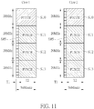
Fig. 11 is a schematic diagram of arrangement of subband units according to an example of the present invention. There are 4 subband units SU0-SU3 in an unlicensed serving cell, a bandwidth of each of the subband units SU0-SU3 is 20 MHz, and a time width of each of the subband units SU0-SU3 is a subframe (or other time unit such as a time slot or a time interval, etc.). Twocases Case 1 andCase 2 are illustrated as follows. InCase 1, the subband unit SU0 is reserved for PUCCH(s), and the communication device can only transmit a SRS and a PUSCH in one or more of the subband units SU1-SU3. The communication device transmits a SRS in a time period T1 of one or more of the subband units SU1-SU3 in the subframe to the network. In addition, the communication device transmits a PUSCH in a time period T2 of one or more of the subband units SU1-SU3 in the subframe to the network. InCase 2, the communication device transmits a SRS in a time period T1 of one or more of the subband units SU0-SU3 in the subframe to the network. In addition, the communication device transmits a PUSCH in a time period T2 of one or more of the subband units SU1-SU3 in the subframe to the network. The communication device transmits a PUCCH in a time period T2 of the subband unit SU0 in the subframe to the network. That is, the PUCCH can only be transmitted in part of the subband unit SU0. As can be seen, the SRS is transmitted before the PUSCH in the time domain in both cases. It should be noted that one or more of the subband units SU0-SU3 may not be used for transmitting the corresponding SRS, the corresponding PUSCH and/or the corresponding PUCCH, if a result of a LBT indicates that the one or more of the subband units SU1-SU3 is not clear. That is, the transmission(s) may be performed according to the result of the LBT performed in the subband unit(s). -
Fig. 12 is a schematic diagram of arrangement of subband units according to an example of the present invention. There are 4 subband units SU0-SU3 in an unlicensed serving cell, a bandwidth of each of the subband units SU0-SU3 is 20 MHz, and a time width of each of the subband units SU0-SU3 is a subframe (or other time unit such as a time slot or a time interval, etc.). Three SRSs SRS0-SRS2 are scheduled to be transmitted via the subband units SU1-SU3, respectively. Each of the SRSs SRS0-SRS2 is a complete SRS, and is generated for a corresponding subband unit. For example, the SRS SRS1 is generated for the subband unit SU2. In the present example, the communication device transmits the SRSs SRS0-SRS2 in a time period T1 of the subband units SU1-SU3 in the subframe to the network. In addition, the communication device transmits a PUSCH in a time period T2 of the subband unit SU2 in the subframe to the network, wherein the time period T2 is after the time period T1. It should be noted that one or more of the subband units SU1-SU3 may not be used for transmitting the corresponding SRS and/or the corresponding PUSCH, if a result of a LBT indicates that the one or more of the subband units SU1-SU3 is not clear. That is, the transmission(s) may be performed according to the result of the LBT performed in the subband unit(s). In this situation, the network can still receive the SRS(s) correctly, because the SRS(s) is generated separately for the corresponding subband unit(s). - It should be noted that a subband unit may be named as an unlicensed subband unit, a LAA subband unit, a resource group, an unlicensed resource group, a LAA resource group, a PRB group, an unlicensed PRB group, a LAA PRB group, and is not limited herein. A bandwidth of a subband unit may be 2.5 MHz, 3 MHz, 4 MHz, etc. A time width of the subband unit may be one or more subframes, one or more time slots, or one or more time intervals. In addition, the features and/or the operations of a communication device mentioned above may imply corresponding features and/or operations of the network, but is not limited herein.
- Those skilled in the art should readily make combinations, modifications and/or alterations on the abovementioned description and examples. The abovementioned description, steps and/or processes including suggested steps can be realized by means that could be hardware, software, firmware (known as a combination of a hardware device and computer instructions and data that reside as read-only software on the hardware device), an electronic system, or combination thereof. An example of the means may be the
communication device 20. - Examples of the hardware may include analog circuit(s), digital circuit(s) and/or mixed circuit(s). For example, the hardware may include ASIC(s), field programmable gate array(s) (FPGA(s)), programmable logic device(s), coupled hardware components or combination thereof. In another example, the hardware may include general-purpose processor(s), microprocessor(s), controller(s), digital signal processor(s) (DSP(s)) or combination thereof.
- Examples of the software may include set(s) of codes, set(s) of instructions and/or set(s) of functions retained (e.g., stored) in a storage unit, e.g., a computer-readable medium. The computer-readable medium may include SIM, ROM, flash memory, RAM, CD-ROM/DVD-ROM/BD-ROM, magnetic tape, hard disk, optical data storage device, non-volatile storage unit, or combination thereof. The computer-readable medium (e.g., storage unit) may be coupled to at least one processor internally (e.g., integrated) or externally (e.g., separated). The at least one processor which may include one or more modules may (e.g., be configured to) execute the software in the computer-readable medium. The set(s) of codes, the set(s) of instructions and/or the set(s) of functions may cause the at least one processor, the module(s), the hardware and/or the electronic system to perform the related steps.
- Examples of the electronic system may include a system on chip (SoC), system in package (SiP), a computer on module (CoM), a computer program product, an apparatus, a mobile phone, a laptop, a tablet computer, an electronic book or a portable computer system, and the
communication device 20. - To sum up, the present invention provides device and a method for handling transmission/reception for a serving cell. A communication device may perform a LBT and a measurement simultaneously in the same or different subband unit(s), to accelerate the completeness of control-related procedures. Thus, efficiency of the communication between the communication device and the network is improved. In addition, a method for transmitting a SRS, a PUCCH and/or a PUSCH is provided for the serving cell. Thus, the problem of transmitting the UCI via the serving cell is solved.
Claims (17)
- A communication device for handling transmission/reception for a serving cell, characterized by the communication device comprising:a storage unit, for storing instructions of:receiving an indication indicating at least one subband unit of a serving cell from a network; andperforming a communication operation in the at least one subband unit with the network, after receiving the indication; anda processing circuit, coupled to the storage unit, configured to execute the instructions stored in the storage unit.
- The communication device of claim 1, characterized in that the communication operation comprises a listen before talk (LBT) performed in a first set of the at least one subband unit.
- The communication device of claim 2, characterized in that the storage unit further stores the instruction of:transmitting data and/or control information via the first set of the at least one subband unit to the network according a result of the LBT.
- The communication device of claim 1, characterized in that the communication operation comprises a measurement performed in a second set of the at least one subband unit.
- The communication device of claim 4, characterized in that the storage unit further stores the instructions of:performing a LBT in a third set of the at least one subband unit; andtransmitting a measurement result of the measurement via the third set of the at least one subband unit according to a result of the LBT.
- The communication device of claim 5, characterized in that the measurement result comprises a LBT successful rate of the third set of the at least one subband unit.
- The communication device of any of claims 1-6, characterized in that a location or a bandwidth of the at least one subband unit is determined according to a bandwidth of the serving cell, or is determined according to a higher layer signaling transmitted by the network.
- A communication device for handling transmission/reception for a serving cell, characterized by the communication device comprising:a storage unit, for storing instructions of:transmitting a physical uplink (UL) shared channel (PUSCH) in at least one first subband unit of a serving cell to a network; andtransmitting a physical UL control channel (PUCCH) accompanied with the PUSCH via the serving cell to the network according to a multiplexing scheme; anda processing circuit, coupled to the storage unit, configured to execute the instructions stored in the storage unit.
- The communication device of claim 8, characterized in that the multiplexing scheme is a frequency-division multiplexing (FDM) scheme, and the PUCCH is transmitted in at least one second subband unit of the serving cell.
- The communication device of claim 8, characterized in that the multiplexing scheme is a time-division multiplexing (TDM) scheme, and the PUSCH is transmitted in the at least one first subband unit before the PUCCH.
- The communication device of any of claims 8-10, characterized in that a location or a bandwidth of the at least one first subband unit is determined according to a bandwidth of the serving cell, or is determined according to a higher layer signaling transmitted by the network.
- A communication device for handling transmission/reception for a serving cell, characterized by the communication device comprising:a storage unit, for storing instructions of:transmitting a sounding reference signal (SRS) in a first time period of at least one first subband unit of a serving cell in a time interval to a network; andtransmitting a physical uplink (UL) shared channel (PUSCH) in a second time period of at least one second subband unit of the serving cell in the time interval to the network, wherein the second time period is after the first time period; anda processing circuit, coupled to the storage unit, configured to execute the instructions stored in the storage unit.
- The communication device of claim 12, characterized in that a length of the time interval and a time width of one of the at least one first subband unit are the same.
- The communication device of claim 12, characterized in that the SRS comprises at least one SRS transmitted in the at least one first subband unit, respectively.
- The communication device of any of claims 12-14, characterized in that the storage unit further stores an instruction of:transmitting a physical UL control channel (PUCCH) in a third time period of at least one third subband unit of the serving cell in the time interval to the network.
- The communication device of claim 15, characterized in that the third time period is after the second time period, a length of the third time period is a sum of a length of the first time period and a length of the second time period, or a length of the third time period and a length of the second time period are the same.
- The communication device of any of claims 12-16, characterized in that a location or a bandwidth of the at least one first subband unit and/or a location or a bandwidth of the at least one second subband unit is determined according to a bandwidth of the serving cell or is determined according to a higher layer signaling transmitted by the network.
Applications Claiming Priority (2)
| Application Number | Priority Date | Filing Date | Title |
|---|---|---|---|
| US201662276240P | 2016-01-08 | 2016-01-08 | |
| US15/397,688 US11240842B2 (en) | 2016-01-08 | 2017-01-03 | Device and method of handling transmission/reception for serving cell |
Publications (2)
| Publication Number | Publication Date |
|---|---|
| EP3190740A2 true EP3190740A2 (en) | 2017-07-12 |
| EP3190740A3 EP3190740A3 (en) | 2017-07-19 |
Family
ID=57956070
Family Applications (1)
| Application Number | Title | Priority Date | Filing Date |
|---|---|---|---|
| EP17150381.6A Pending EP3190740A3 (en) | 2016-01-08 | 2017-01-05 | Device and method of handling transmission/reception for serving cell |
Country Status (4)
| Country | Link |
|---|---|
| US (1) | US11240842B2 (en) |
| EP (1) | EP3190740A3 (en) |
| CN (1) | CN106961737B (en) |
| TW (1) | TWI672970B (en) |
Cited By (1)
| Publication number | Priority date | Publication date | Assignee | Title |
|---|---|---|---|---|
| WO2020062056A1 (en) * | 2018-09-28 | 2020-04-02 | Lenovo (Beijing) Limited | Method and apparatus for subband based channel access on unlicensed spectrum |
Families Citing this family (6)
| Publication number | Priority date | Publication date | Assignee | Title |
|---|---|---|---|---|
| TWI667934B (en) * | 2016-09-14 | 2019-08-01 | 聯發科技股份有限公司 | Methods for short pucch configuration |
| CA3051926C (en) * | 2017-02-01 | 2022-07-26 | Guangdong Oppo Mobile Telecommunications Corp., Ltd. | Communication method, network device and terminal |
| US10750529B2 (en) * | 2017-06-16 | 2020-08-18 | Motorola Mobility Llc | Method and apparatus for communicating over a long physical uplink channel resource |
| CN110831231B (en) * | 2018-08-10 | 2021-08-24 | 展讯通信(上海)有限公司 | Uplink data transmission method, user terminal and computer readable storage medium |
| CN111030788B (en) * | 2018-10-10 | 2022-05-31 | 上海朗帛通信技术有限公司 | Method and device used in user equipment and base station for wireless communication |
| CN113924811A (en) * | 2019-04-05 | 2022-01-11 | 弗劳恩霍夫应用研究促进协会 | NR-U broadband enhancement |
Family Cites Families (28)
| Publication number | Priority date | Publication date | Assignee | Title |
|---|---|---|---|---|
| JP2009065403A (en) | 2007-09-06 | 2009-03-26 | Nec Corp | Method and device for estimating reception quality in radio communication |
| JP5792615B2 (en) * | 2008-06-11 | 2015-10-14 | ノキア ソリューションズ アンド ネットワークス オサケユキチュア | Local area optimized uplink control channel |
| CA2750580C (en) * | 2009-01-30 | 2016-05-10 | Samsung Electronics Co., Ltd. | Control signaling for transmissions over contiguous and non-contiguous frequency bands |
| US8938247B2 (en) | 2009-04-23 | 2015-01-20 | Qualcomm Incorporated | Sounding reference signal for coordinated multi-point operation |
| CN101925113B (en) * | 2009-06-12 | 2013-06-12 | 电信科学技术研究院 | Transmission processing method and equipment of uplink control channel |
| KR101639407B1 (en) | 2009-07-30 | 2016-07-13 | 엘지전자 주식회사 | Apparatus and method for transmitting channel state information in a mobile communication system |
| WO2011055940A2 (en) | 2009-11-05 | 2011-05-12 | 엘지전자 주식회사 | Method for transmitting channel quality information, and apparatus for same |
| KR101751060B1 (en) | 2009-12-18 | 2017-06-28 | 엘지전자 주식회사 | Method and apparatus of allocating sounding channel in wireless communication system |
| WO2011123805A1 (en) | 2010-04-02 | 2011-10-06 | Interdigital Patent Holdings, Inc. | Uplink sounding reference signals configuration and transmission |
| US20120113827A1 (en) | 2010-11-08 | 2012-05-10 | Sharp Laboratories Of America, Inc. | Dynamic simultaneous pucch and pusch switching for lte-a |
| KR20120071654A (en) * | 2010-12-23 | 2012-07-03 | 한국전자통신연구원 | Method of controlling interference from femto cells in consideration of macrocell |
| WO2012144801A2 (en) | 2011-04-18 | 2012-10-26 | 엘지전자 주식회사 | Signal transmission method and device in a wireless communication system |
| GB2495991A (en) * | 2011-10-28 | 2013-05-01 | Renesas Mobile Corp | Mapping long term evolution (LTE) control channels to television channel white spaces (TVWS) |
| US9572148B2 (en) | 2011-12-07 | 2017-02-14 | Lg Electronics Inc. | Method and apparatus for transceiving a downlink control channel in a wireless communication system |
| US9485683B2 (en) | 2012-05-31 | 2016-11-01 | Interdigital Patent Holdings, Inc. | Sensing measurement configuration and reporting in a long term evolution system operating over license exempt bands |
| WO2013191441A1 (en) | 2012-06-18 | 2013-12-27 | Samsung Electronics Co., Ltd. | Aperiodic and periodic csi feedback modes for coordinated multi-point transmission |
| CN103813433A (en) * | 2012-11-09 | 2014-05-21 | 北京三星通信技术研究有限公司 | Method and equipment for power control in cross-eNB carrier aggregation system |
| US9949275B2 (en) * | 2013-10-01 | 2018-04-17 | Qualcomm Incorporated | Physical uplink control management in LTE/LTE-A systems with unlicensed spectrum |
| US10142945B2 (en) * | 2014-06-05 | 2018-11-27 | Samsung Electronics Co., Ltd. | Power control for transmission of uplink control information on two cells in carrier aggregation |
| US10560891B2 (en) * | 2014-09-09 | 2020-02-11 | Blackberry Limited | Medium Access Control in LTE-U |
| US20160088594A1 (en) * | 2014-09-18 | 2016-03-24 | Gang Xiong | Device and method of supporting reduced data transmission bandwidth |
| US20180115983A1 (en) * | 2014-11-06 | 2018-04-26 | Ntt Docomo, Inc. | User terminal and radio communication system |
| WO2016111549A1 (en) * | 2015-01-06 | 2016-07-14 | 엘지전자 주식회사 | Downlink signal reception method and user equipment, and downlink signal transmission method and base station |
| CN107431591B (en) * | 2015-01-28 | 2020-09-25 | 交互数字专利控股公司 | Method and apparatus for uplink operation of LTE in unlicensed frequency bands |
| JP6100829B2 (en) * | 2015-05-14 | 2017-03-22 | 株式会社Nttドコモ | User terminal, radio base station, and radio communication method |
| EP3357184B1 (en) * | 2015-10-01 | 2023-06-28 | Nokia Solutions and Networks Oy | Method, apparatus and computer program for transmitting physical layer signals |
| US10355830B2 (en) * | 2015-12-07 | 2019-07-16 | Telefonaktiebolaget Lm Ericsson (Publ) | Uplink mac protocol aspects |
| EP3387771A1 (en) * | 2015-12-08 | 2018-10-17 | Nokia Solutions and Networks Oy | Hybrid automatic repeat request acknowledgement feedback using periodic and aperiodic physical uplink control channel resources |
-
2017
- 2017-01-03 US US15/397,688 patent/US11240842B2/en active Active
- 2017-01-04 TW TW106100105A patent/TWI672970B/en active
- 2017-01-05 CN CN201710008246.7A patent/CN106961737B/en active Active
- 2017-01-05 EP EP17150381.6A patent/EP3190740A3/en active Pending
Non-Patent Citations (1)
| Title |
|---|
| None |
Cited By (1)
| Publication number | Priority date | Publication date | Assignee | Title |
|---|---|---|---|---|
| WO2020062056A1 (en) * | 2018-09-28 | 2020-04-02 | Lenovo (Beijing) Limited | Method and apparatus for subband based channel access on unlicensed spectrum |
Also Published As
| Publication number | Publication date |
|---|---|
| CN106961737B (en) | 2021-04-02 |
| TWI672970B (en) | 2019-09-21 |
| EP3190740A3 (en) | 2017-07-19 |
| US11240842B2 (en) | 2022-02-01 |
| TW201725930A (en) | 2017-07-16 |
| US20170202021A1 (en) | 2017-07-13 |
| CN106961737A (en) | 2017-07-18 |
Similar Documents
| Publication | Publication Date | Title |
|---|---|---|
| US11240842B2 (en) | Device and method of handling transmission/reception for serving cell | |
| US9668288B2 (en) | Method of handling device-to-device operation and related communication device | |
| EP3236704B1 (en) | Device and method of handling device-to-device communication | |
| US11452091B2 (en) | Device and method of handling hybrid automatic repeat request transmission | |
| US10477486B2 (en) | Device and method of handling uplink power control | |
| US9882699B2 (en) | Device and method of handling device-to-cellular communication | |
| EP3349502A1 (en) | Device and method of handling channel status information reports for transmission time intervals | |
| US11871363B2 (en) | Device and method of handling power headroom report for multiple time intervals | |
| US20150098370A1 (en) | Method of Handling HARQ Resource for FDD Carrier and Related Communication Device | |
| EP2903382B1 (en) | Method of handling device-to-device signal and device-to-cellular signal | |
| US10477436B2 (en) | Device and method of handling transmission in unlicensed band |
Legal Events
| Date | Code | Title | Description |
|---|---|---|---|
| PUAI | Public reference made under article 153(3) epc to a published international application that has entered the european phase |
Free format text: ORIGINAL CODE: 0009012 |
|
| STAA | Information on the status of an ep patent application or granted ep patent |
Free format text: STATUS: THE APPLICATION HAS BEEN PUBLISHED |
|
| PUAL | Search report despatched |
Free format text: ORIGINAL CODE: 0009013 |
|
| AK | Designated contracting states |
Kind code of ref document: A2 Designated state(s): AL AT BE BG CH CY CZ DE DK EE ES FI FR GB GR HR HU IE IS IT LI LT LU LV MC MK MT NL NO PL PT RO RS SE SI SK SM TR |
|
| AX | Request for extension of the european patent |
Extension state: BA ME |
|
| AK | Designated contracting states |
Kind code of ref document: A3 Designated state(s): AL AT BE BG CH CY CZ DE DK EE ES FI FR GB GR HR HU IE IS IT LI LT LU LV MC MK MT NL NO PL PT RO RS SE SI SK SM TR |
|
| AX | Request for extension of the european patent |
Extension state: BA ME |
|
| RIC1 | Information provided on ipc code assigned before grant |
Ipc: H04W 74/08 20090101ALI20170614BHEP Ipc: H04L 5/00 20060101AFI20170614BHEP Ipc: H04L 27/00 20060101ALN20170614BHEP |
|
| STAA | Information on the status of an ep patent application or granted ep patent |
Free format text: STATUS: REQUEST FOR EXAMINATION WAS MADE |
|
| 17P | Request for examination filed |
Effective date: 20180118 |
|
| RBV | Designated contracting states (corrected) |
Designated state(s): AL AT BE BG CH CY CZ DE DK EE ES FI FR GB GR HR HU IE IS IT LI LT LU LV MC MK MT NL NO PL PT RO RS SE SI SK SM TR |
|
| STAA | Information on the status of an ep patent application or granted ep patent |
Free format text: STATUS: EXAMINATION IS IN PROGRESS |
|
| 17Q | First examination report despatched |
Effective date: 20180808 |
|
| STAA | Information on the status of an ep patent application or granted ep patent |
Free format text: STATUS: EXAMINATION IS IN PROGRESS |
|
| STAA | Information on the status of an ep patent application or granted ep patent |
Free format text: STATUS: EXAMINATION IS IN PROGRESS |