EP3190733A1 - Communication device and method - Google Patents
Communication device and method Download PDFInfo
- Publication number
- EP3190733A1 EP3190733A1 EP17157326.4A EP17157326A EP3190733A1 EP 3190733 A1 EP3190733 A1 EP 3190733A1 EP 17157326 A EP17157326 A EP 17157326A EP 3190733 A1 EP3190733 A1 EP 3190733A1
- Authority
- EP
- European Patent Office
- Prior art keywords
- srs
- preamble
- transmitted
- random access
- mobile station
- Prior art date
- Legal status (The legal status is an assumption and is not a legal conclusion. Google has not performed a legal analysis and makes no representation as to the accuracy of the status listed.)
- Granted
Links
- 238000004891 communication Methods 0.000 title claims abstract description 35
- 238000000034 method Methods 0.000 title description 5
- 230000001360 synchronised effect Effects 0.000 claims 2
- 125000004122 cyclic group Chemical group 0.000 abstract description 2
- 230000005540 biological transmission Effects 0.000 description 288
- 238000012545 processing Methods 0.000 description 27
- 238000001514 detection method Methods 0.000 description 14
- 238000006243 chemical reaction Methods 0.000 description 12
- 238000010586 diagram Methods 0.000 description 10
- 230000000694 effects Effects 0.000 description 7
- 230000007274 generation of a signal involved in cell-cell signaling Effects 0.000 description 6
- 101100151946 Caenorhabditis elegans sars-1 gene Proteins 0.000 description 5
- 230000003111 delayed effect Effects 0.000 description 4
- 238000005516 engineering process Methods 0.000 description 4
- 238000010295 mobile communication Methods 0.000 description 4
- 230000010354 integration Effects 0.000 description 3
- 238000013507 mapping Methods 0.000 description 3
- 238000007796 conventional method Methods 0.000 description 2
- 230000007423 decrease Effects 0.000 description 2
- 230000001934 delay Effects 0.000 description 1
- 239000000284 extract Substances 0.000 description 1
- 230000007774 longterm Effects 0.000 description 1
- 238000004519 manufacturing process Methods 0.000 description 1
- 239000004065 semiconductor Substances 0.000 description 1
Images


Classifications
-
- H—ELECTRICITY
- H04—ELECTRIC COMMUNICATION TECHNIQUE
- H04L—TRANSMISSION OF DIGITAL INFORMATION, e.g. TELEGRAPHIC COMMUNICATION
- H04L27/00—Modulated-carrier systems
- H04L27/26—Systems using multi-frequency codes
- H04L27/2601—Multicarrier modulation systems
- H04L27/2602—Signal structure
- H04L27/261—Details of reference signals
- H04L27/2613—Structure of the reference signals
- H04L27/26134—Pilot insertion in the transmitter chain, e.g. pilot overlapping with data, insertion in time or frequency domain
-
- H—ELECTRICITY
- H04—ELECTRIC COMMUNICATION TECHNIQUE
- H04L—TRANSMISSION OF DIGITAL INFORMATION, e.g. TELEGRAPHIC COMMUNICATION
- H04L27/00—Modulated-carrier systems
- H04L27/26—Systems using multi-frequency codes
- H04L27/2601—Multicarrier modulation systems
- H04L27/2602—Signal structure
- H04L27/261—Details of reference signals
- H04L27/2613—Structure of the reference signals
-
- H—ELECTRICITY
- H04—ELECTRIC COMMUNICATION TECHNIQUE
- H04L—TRANSMISSION OF DIGITAL INFORMATION, e.g. TELEGRAPHIC COMMUNICATION
- H04L27/00—Modulated-carrier systems
- H04L27/26—Systems using multi-frequency codes
- H04L27/2601—Multicarrier modulation systems
- H04L27/2602—Signal structure
- H04L27/2605—Symbol extensions, e.g. Zero Tail, Unique Word [UW]
- H04L27/2607—Cyclic extensions
-
- H—ELECTRICITY
- H04—ELECTRIC COMMUNICATION TECHNIQUE
- H04L—TRANSMISSION OF DIGITAL INFORMATION, e.g. TELEGRAPHIC COMMUNICATION
- H04L5/00—Arrangements affording multiple use of the transmission path
- H04L5/0001—Arrangements for dividing the transmission path
- H04L5/0003—Two-dimensional division
- H04L5/0005—Time-frequency
- H04L5/0007—Time-frequency the frequencies being orthogonal, e.g. OFDM(A), DMT
-
- H—ELECTRICITY
- H04—ELECTRIC COMMUNICATION TECHNIQUE
- H04L—TRANSMISSION OF DIGITAL INFORMATION, e.g. TELEGRAPHIC COMMUNICATION
- H04L5/00—Arrangements affording multiple use of the transmission path
- H04L5/003—Arrangements for allocating sub-channels of the transmission path
- H04L5/0048—Allocation of pilot signals, i.e. of signals known to the receiver
- H04L5/0051—Allocation of pilot signals, i.e. of signals known to the receiver of dedicated pilots, i.e. pilots destined for a single user or terminal
-
- H—ELECTRICITY
- H04—ELECTRIC COMMUNICATION TECHNIQUE
- H04L—TRANSMISSION OF DIGITAL INFORMATION, e.g. TELEGRAPHIC COMMUNICATION
- H04L5/00—Arrangements affording multiple use of the transmission path
- H04L5/003—Arrangements for allocating sub-channels of the transmission path
- H04L5/0053—Allocation of signaling, i.e. of overhead other than pilot signals
-
- H—ELECTRICITY
- H04—ELECTRIC COMMUNICATION TECHNIQUE
- H04L—TRANSMISSION OF DIGITAL INFORMATION, e.g. TELEGRAPHIC COMMUNICATION
- H04L5/00—Arrangements affording multiple use of the transmission path
- H04L5/003—Arrangements for allocating sub-channels of the transmission path
- H04L5/0078—Timing of allocation
- H04L5/0082—Timing of allocation at predetermined intervals
-
- H—ELECTRICITY
- H04—ELECTRIC COMMUNICATION TECHNIQUE
- H04W—WIRELESS COMMUNICATION NETWORKS
- H04W40/00—Communication routing or communication path finding
- H04W40/24—Connectivity information management, e.g. connectivity discovery or connectivity update
- H04W40/246—Connectivity information discovery
-
- H—ELECTRICITY
- H04—ELECTRIC COMMUNICATION TECHNIQUE
- H04W—WIRELESS COMMUNICATION NETWORKS
- H04W72/00—Local resource management
- H04W72/04—Wireless resource allocation
- H04W72/044—Wireless resource allocation based on the type of the allocated resource
- H04W72/0446—Resources in time domain, e.g. slots or frames
-
- H—ELECTRICITY
- H04—ELECTRIC COMMUNICATION TECHNIQUE
- H04W—WIRELESS COMMUNICATION NETWORKS
- H04W74/00—Wireless channel access, e.g. scheduled or random access
-
- H—ELECTRICITY
- H04—ELECTRIC COMMUNICATION TECHNIQUE
- H04W—WIRELESS COMMUNICATION NETWORKS
- H04W74/00—Wireless channel access, e.g. scheduled or random access
- H04W74/08—Non-scheduled or contention based access, e.g. random access, ALOHA, CSMA [Carrier Sense Multiple Access]
- H04W74/0808—Non-scheduled or contention based access, e.g. random access, ALOHA, CSMA [Carrier Sense Multiple Access] using carrier sensing, e.g. as in CSMA
- H04W74/0816—Non-scheduled or contention based access, e.g. random access, ALOHA, CSMA [Carrier Sense Multiple Access] using carrier sensing, e.g. as in CSMA carrier sensing with collision avoidance
-
- H—ELECTRICITY
- H04—ELECTRIC COMMUNICATION TECHNIQUE
- H04W—WIRELESS COMMUNICATION NETWORKS
- H04W74/00—Wireless channel access, e.g. scheduled or random access
- H04W74/08—Non-scheduled or contention based access, e.g. random access, ALOHA, CSMA [Carrier Sense Multiple Access]
- H04W74/0833—Non-scheduled or contention based access, e.g. random access, ALOHA, CSMA [Carrier Sense Multiple Access] using a random access procedure
-
- H—ELECTRICITY
- H04—ELECTRIC COMMUNICATION TECHNIQUE
- H04W—WIRELESS COMMUNICATION NETWORKS
- H04W76/00—Connection management
- H04W76/10—Connection setup
- H04W76/14—Direct-mode setup
Definitions
- the present invention relates to a radio communication base station apparatus and an association setting method.
- the 3GPP RAN LTE Long Term Evolution
- SRSs Sounding Reference Signals
- CQI Channel Quality Indicator
- base station a radio communication base station apparatus
- a mobile station located at a cell edge where the propagation condition is poor and transmission power is limited does not have power necessary to transmit a wideband SRS, and so the mobile station transmits a narrowband (e.g. 1.25 MHz) SRS.
- a narrowband SRS e.g. 1.25 MHz
- wideband CQI estimation is performed over a plurality of transmission time fields by performing frequency hopping.
- the 3GPP RAN LTE is studying the use of random access preamble (hereinafter abbreviated as a "preamble") for initial access of a mobile station, updating of transmission timing and CQI estimation on uplink from a mobile station to a base station (e.g. see Non-Patent Document 2).
- a preamble is a signal including identification information about a mobile station, and each mobile station randomly selects one of a plurality of code sequences set up in advance by a base station or selects one code sequence according to command from the base station. Each mobile station then transmits a preamble generated based on the selected code sequence to the base station.
- a preamble transmitted from a mobile station which has not established synchronization with a base station on uplink entails a delay matching the round trip propagation delay time (RTD) at reception timing at the time of reception in the base station. Therefore, a guard time is set in the preamble as described above to prevent the preamble from delaying and causing interference with the signal of the next subframe.
- RTD round trip propagation delay time
- an SRS When transmitting an SRS, resources of the time domain and frequency domain may be assigned thereto exclusive of other signals (e.g. see Non-Patent Document 3).
- PUSCH Physical Uplink Shared Channel
- the first LB in a subframe is more frequently used to transmit the SRS as the number of mobile stations in a cell increases. That is, the proportion of communication resources used to transmit SRSs increases as the number of mobile stations in the cell increases. Therefore, according to the above-described conventional technique, when the number of mobile stations within the cell increases, communication resources available for data transmission decrease, and, as a result, the data transmission efficiency is reduced.
- the radio communication base station apparatus of the present invention adopts a configuration including a receiving section that receives a first signal which is provide with a guard time and which is transmitted periodically, and a second signal which is transmitted periodically, a setting section that sets an association between the first signal and the second signal such that a first transmission field for the first signal matches a second transmission field for the second signal, and a determining section that determines the second transmission field based on the first transmission field and the association.
- the amount of communication resources used for SRSs can be reduced.
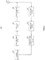
- FIG.1 shows a configuration of base station 100 according to the present embodiment.
- Base station 100 receives a preamble from mobile station 200 ( FIG.2 ) which will be described later and receives an SRS from mobile station 300 ( FIG.3 ) which will be described later.
- Preamble transmission field determining section 101 determines the time interval of the transmission time field (subframe) in which the mobile station can transmit a preamble. Preamble transmission field determining section 101 then outputs the determined preamble transmission time interval to SRS transmission field determining section 103, control signal generation section 104 and time field identifying section 109.
- Association rule setting section 102 sets rules for associating the transmission time intervals for the preamble and SRS. Association rule setting section 102 then outputs the association rules set, to SRS transmission field determining section 103. Details of the setting of the association rules in association rule setting section 102 will be described later.
- SRS transmission field determining section 103 determines the time interval of the transmission time field (subframe) in which the SRS can be transmitted, based on the preamble transmission time interval inputted from preamble transmission field determining section 101 and the association rules inputted from association rule setting section 102. SRS transmission field determining section 103 then outputs the determined SRS transmission time interval to control signal generation section 104 and time field identifying section 109. Details of the processing of determining the SRS transmission time field in SRS transmission field determining section 103 will be described later.
- Control signal generation section 104 generates a control signal including the preamble transmission time interval inputted from preamble transmission field determining section 101 and the SRS transmission time interval inputted from SRS transmission field determining section 103. Control signal generation section 104 then outputs the control signal generated to modulation section 105.
- Modulation section 105 modulates the control signal inputted from control signal generation section 104 and outputs the modulated control signal to radio transmitting section 106.
- Radio transmitting section 106 performs radio processing such as D/A conversion, up-conversion on the control signal and transmits the control signal to mobile station 200 and mobile station 300 via antenna 107.
- radio receiving section 108 receives a signal transmitted from mobile station 200 and mobile station 300 via antenna 107, performs radio processing such as down-conversion, A/D conversion on the received signal and outputs the received signal to time field identifying section 109.
- Time field identifying section 109 identifies the preamble transmission time field (subframe) and the SRS transmission time field (subframe) based on the preamble transmission time interval inputted from preamble transmission field determining section 101 and the SRS transmission time interval inputted from SRS transmission field determining section 103, outputs the received preamble to demodulation section 110 and the received SRS to demodulation section 112.
- Demodulation section 110 demodulates the preamble inputted from time field identifying section 109 and outputs the demodulated preamble to preamble detection section 111.
- Preamble detection section 111 determines the correlation between the known preamble code sequence set up in advance in the system and the preamble inputted from demodulation section 110, and detects the preamble. Preamble detection section 111 then outputs a preamble detection result indicating the detected preamble.
- Demodulation section 112 demodulates the SRS inputted from time field identifying section 109 and outputs the demodulated SRS to CQI estimation section 113.
- CQI estimation section 113 performs CQI estimation based on the SRS inputted from demodulation section 112. CQI estimation section 113 then outputs the estimated CQI estimate value.
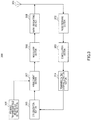
- FIG.2 shows a configuration of mobile station 200 according to the present embodiment.
- Mobile station 200 transmits a preamble to base station 100 ( FIG.1 ).
- Radio receiving section 202 receives a control signal transmitted from base station 100 via antenna 201, performs radio processing such as down-conversion, A/D conversion on the control signal and outputs the control signal to demodulation section 203.
- Demodulation section 203 demodulates the control signal and outputs the demodulated control signal to transmission time interval detection section 204.
- Transmission time interval detection section 204 detects the preamble transmission time interval included in the control signal inputted from demodulation section 203 and outputs the detected preamble transmission time interval to preamble generation section 205.
- Preamble generation section 205 randomly selects one preamble code sequence from known preamble code sequences set up in advance in the system in the preamble transmission time field (subframe) obtained based on the preamble transmission time interval inputted from transmission time interval detection section 204. Preamble generation section 205 then generates a preamble based on the selected code sequence. Preamble generation section 205 then outputs the preamble generated to guard time adding section 206.
- Guard time adding section 206 adds a guard time of a predetermined time length to the preamble inputted from preamble generation section 205. Guard time adding section 206 then outputs the preamble with a guard time to modulation section 207.
- Modulation section 207 modulates the preamble and outputs the modulated preamble to radio transmitting section 208.
- Radio transmitting section 208 performs radio processing such as D/A conversion, up-conversion on the preamble inputted from modulation section 207 and transmits the preamble to base station 100 via antenna 201.
- FIG.3 shows a configuration of mobile station 300 according to the present embodiment.
- Mobile station 300 transmits the SRS to base station 100 ( FIG. 1 ).
- Radio receiving section 302 receives a control signal transmitted from base station 100 via antenna 301, performs radio processing such as down-conversion and A/D conversion on the control signal, and outputs the control signal to demodulation section 303.
- Demodulation section 303 demodulates the control signal and outputs the demodulated control signal to transmission time interval detection section 304.
- Transmission time interval detection section 304 detects the SRS transmission time interval included in the control signal inputted from demodulation section 303, and outputs the detected SRS transmission time interval to SRS generation section 305.
- SRS generation section 305 generates a known SRS code sequence commanded from base station 100 in advance, in the SRS transmission time field (subframe) obtained based on the SRS transmission time interval inputted from transmission time interval detection section 304. SRS generation section 305 then outputs the generated SRS to arrangement section 307.
- Preamble transmission field information setting section 306 sets the positions and time lengths of the CP, preamble and guard time in the preamble transmission time field. Preamble transmission field information setting section 306 then outputs preamble transmission field information indicating the positions and time lengths of the CP, preamble and guard time in the preamble transmission time field, to arrangement section 307.
- Arrangement section 307 arranges the SRS in the preamble transmission time field (subframe) based on the preamble transmission field information inputted from preamble transmission field information setting section 306. To be more specific, arrangement section 307 arranges the SRS in the guard time position in the preamble. For example, arrangement section 307 arranges the SRS in the guard time position in the preamble such that the time interval between the preamble and the SRS becomes maximum. Arrangement section 307 outputs the arranged SRS to modulation section 308. Details of the SRS arrangement processing in arrangement section 307 will be described later.
- Modulation section 308 modulates the SRS and outputs the modulated SRS to radio transmitting section 309.
- Radio transmitting section 309 performs radio processing such as D/A conversion, up-conversion on the SRS inputted from modulation section 308 and transmits the SRS to base station 100 via antenna 301.
- association rule setting section 102 of base station 100 ( FIG. 1 )
- processing of determining the SRS transmission time interval in SRS transmission field determining section 103 and the processing of SRS arrangement in arrangement section 307 of mobile station 300 ( FIG.3 ) will be explained.
- SRS transmission field determining section 103 determines the interval of the SRS transmission time field according to the preamble transmission time interval inputted from preamble transmission field determining section 101 and the rules (m and n) set in association rule setting section 102. That is, SRS transmission field determining section 103 determines the SRS transmission time interval from (m/n) ⁇ (preamble transmission time interval) based on equation 1.
- SRS transmission field determining section 103 determines the SRS transmission time interval to be 5 subframes from (1/2) ⁇ (10 subframes).
- the time interval of the preamble transmission time field is 10 subframes
- the time interval of the SRS transmission time field is 5 subframes.
- the transmission time field of the preamble which requires a longer transmission time interval than the SRS, constantly matches the SRS transmission time field. That is, since part of the SRS transmission time field (half of the whole in FIG.4 ) is transmitted using the same transmission time field as the preamble transmission time field, communication resources used for the SRS can be reduced.
- the preamble transmission time field constantly matches the SRS transmission time field in the transmission time field for one of the preamble and the SRS having the longer time interval of the transmission time field.
- the preamble transmission time field constantly matches the SRS transmission time field, and, consequently, the preamble transmission time field is the only communication resource used for the SRS.
- arrangement section 307 of mobile station 300 ( FIG.3 ) arranges the generated SRS in the position of the guard time in the preamble transmission time field such that the time interval between the preamble and the SRS becomes maximum.
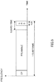
- arrangement section 307 arranges the SRS in the guard time of one subframe including the CP, the preamble and the guard time, as shown in FIG.5 .
- arrangement section 307 arranges the SRS at the tail end of the subframe such that the time interval between the preamble and the SRS becomes maximum as shown in FIG.5 .
- the preamble and the SRS shown in FIG.5 are transmitted from different mobile stations, mobile station 200 ( FIG.2 ) and mobile station 300 ( FIG.3 ). Furthermore, uplink synchronization is established between mobile station 300 that transmits the SRS and base station 100, whereas uplink synchronization is not established between mobile station 200 that transmits the preamble and base station 100. That is, since mobile station 300 transmits the SRS taking into account the RTD between mobile station 300 and base station 100, the SRS reception timing in base station 100 is not delayed. On the other hand, since mobile station 200 transmits the preamble without taking into account the RTD, the preamble reception timing in base station 100 is delayed by the RTD.
- arrangement section 307 of mobile station 300 arranges the SRS at the tail end of the subframe such that the time interval between the preamble and the SRS becomes maximum, even if the preamble reception timing shown in FIG.5 delays into the guard time, base station 100 can minimize interference between the preamble and the SRS.
- the RTD satisfies following equation 2
- no interference occurs between the preamble and the SRS.
- GT is the time length of the guard time of the preamble transmission time field (subframe)
- CP is the CP time length of the SRS (value corresponding to delay spread)
- SRS is the time length of the SRS.
- RTD 26 ⁇ s.
- GT 97.4 ⁇ s
- CP 4.8 ⁇ s
- SRS 66.6 ⁇ s.
- FIG.6 shows an operation sequence of the mobile communication system according to the present embodiment.
- preamble transmission field determining section 101 of base station 100 determines the preamble transmission time interval (e.g. 10 subframes shown in FIG.4 ) first and SRS transmission field determining section 103 determines the SRS transmission time interval (e.g. 5 subframes shown in FIG.4 ). Base station 100 then transmits the preamble transmission time interval and the SRS transmission time interval to mobile station 200 and mobile station 300 respectively.
- preamble transmission time interval e.g. 10 subframes shown in FIG.4
- SRS transmission field determining section 103 determines the SRS transmission time interval (e.g. 5 subframes shown in FIG.4 ).
- Base station 100 then transmits the preamble transmission time interval and the SRS transmission time interval to mobile station 200 and mobile station 300 respectively.
- transmission time interval detection section 204 detects the preamble transmission time interval, and preamble generation section 205 calculates the preamble transmission time field and generates a preamble. Mobile station 200 then transmits the preamble to base station 100.
- transmission time interval detection section 304 detects the SRS transmission time interval
- SRS generation section 305 calculates the SRS transmission time field and generates an SRS.
- arrangement section 307 arranges the SRS in the position of the guard time in the preamble transmission time field. Mobile station 300 then transmits the SRS to base station 100.
- base station 100 receives the preamble from mobile station 200 and the SRS from mobile station 300 according to the preamble transmission time interval and the SRS transmission time interval reported to mobile station 200 and mobile station 300.
- base station 100 receives only the SRS from mobile station 300 in ST 105. Furthermore, in further transmission time interval T (5 subframes) after ST 105, that is, in transmission time interval 2T (10 subframes) after ST 104, base station 100 receives the preamble from mobile station 200 and SRS from mobile station 300 in ST 106.
- the preamble transmission time field not only the preamble but also the SRS is received constantly, and therefore it is possible to reduce the communication resources to be secured for the SRS transmission time field.
- the SRS transmission time interval is associated with the preamble transmission time interval. This allows the SRS transmission time field to match the preamble transmission time field, and therefore it is possible to suppress the amount of communication resources used to transmit the SRS. Furthermore, when the SRS is arranged in the preamble transmission time field, the SRS is arranged in the guard time such that the time interval between the preamble and the SRS becomes maximum, and, therefore, even when the preamble reception timing is delayed, it is possible to minimize interference between the preamble and the SRS.
- the preamble transmission bandwidth (24 RBs) is different from the SRS transmission bandwidth (6 RBs) as shown in FIG.4 , but the preamble transmission bandwidth may be equal to the SRS transmission bandwidth.
- the base station transmits a control signal including an SRS transmission time interval to each mobile station, but it is not necessarily to report the SRS transmission time interval in a control signal to each mobile station.
- the base station may report the association rules to each mobile station.
- each mobile station can calculate the SRS transmission time interval based on the preamble transmission time interval and the association rules.
- the entire system may set in advance the association rules.
- the base station needs to report only the preamble transmission time interval to each mobile station, and therefore can reduce the amount of information for reporting the SRS transmission time interval and the association rules.
- preamble generation section 205 of mobile station 200 ( FIG.2 ) generates a preamble based on a preamble code sequence selected randomly from preamble code sequences set up in advance by the system.
- preamble generation section 205 may also generate a preamble based on a preamble code sequence given from base station 100 ( FIG. 1 ).
- base station 100 indicates the preamble code sequence to mobile station 200, so that the preamble of mobile station 200 does not collide with the preambles of other mobile stations, and therefore it is possible to prevent collision between the preambles based on the same preamble code sequence.
- modulation section 105 ( FIG.1 ) of base station 100 of the present embodiment
- modulation section 207 ( FIG.2 ) of mobile station 200
- the DFT processing transforms the signal from a time domain signal to a frequency domain signal.
- the transmission band mapping processing arranges the signal transformed to a frequency domain signal through the DFT processing in a predetermined transmission band.
- the IFFT processing applies IFFT to the signal subjected to the transmission band mapping processing to transform the signal from a frequency domain signal to a time domain signal.
- demodulation section 110 and demodulation section 112 of base station 100, demodulation section 203 of mobile station 200 and demodulation section 303 of mobile station 300 may perform FFT (Fast Fourier Transform) processing, transmission band demapping processing and IDFT (Inverse Discrete Fourier Transform) processing.
- FFT processing applies FFT to the received signal to transform the signal from a time domain signal to a frequency domain signal.
- transmission band demapping processing extracts a predetermined transmission band including the transmitted signal from the signal transformed to the frequency domain.
- IDFT processing applies IDFT processing to the signal subjected to the transmission band demapping processing to transform the signal from a frequency domain signal to a time domain signal.
- an SRS is arranged at the beginning of a preamble transmission time field.
- Guard time adding section 206 ( FIG.2 ) of mobile station 200 according to the present embodiment adds a guard time of the same time length as the SRS length before the preamble inputted from preamble generation section 205 and also adds a guard time of a time length corresponding to (1 subframe length - preamble length - SRS length) after the preamble.
- arrangement section 307 ( FIG.3 ) of mobile station 300 according to the present embodiment arranges the SRS at the beginning of the preamble transmission time field (subframe).
- arrangement section 307 arranges the generated SRS at the beginning of the preamble transmission time field (subframe).
- mobile station 200 arranges the CP and the preamble directly after the position where the SRS is arranged. That is, as shown in FIG.7 , in mobile station 200, the CP and preamble are arranged in that order from the position 1 LB (i.e. the SRS length) from the beginning of the preamble transmission time field (subframe). Furthermore, as shown in FIG.7 , in 1 subframe, the rest of the transmission time field other than the transmission time field where the SRS and preamble (including the CP) are arranged, constitutes the guard time.
- the SRS from mobile station 300 does not delay in base station 100. Therefore, even when base station 100 receives a signal with no interval between the SRS and the preamble as shown in FIG.7 , the SRS never slips into the rear part where the preamble is arranged, and therefore the SRS and the preamble do not interfere with each other in the same transmission time field.
- the preamble is delayed by the RTD.
- the present embodiment eliminates the interval between the SRS and the preamble and secures a maximal guard time after the preamble. Therefore, when the RTD satisfies equation 1, base station 100 can prevent interference between the preamble and the signal of the next transmission time field (subframe) as in the case of Embodiment 1.
- the SRS is arranged at the beginning of the preamble transmission time field. This makes it possible to provide similar effects to Embodiment 1 and prevent interference between the SRS and the preamble completely.
- Embodiment 1 A case has been described with Embodiment 1 where the preamble and SRS transmission time fields are made to match each other, but a case will be explained now with the present embodiment where the preamble and SRS transmission time fields and the transmission band are made to match each other.
- FIG.8 shows a configuration of base station 400 according to the present embodiment.
- the same components as those in Embodiment 1 FIG.1
- Preamble transmission field determining section 401 of base station 400 determines a time interval (subframe) in which each mobile station can transmit the preamble and a transmission band in which the preamble can be transmitted.
- Association rule setting section 402 sets a rule for associating the preamble and SRS transmission time intervals with their transmission bands. Details of the setting of association rules in association rule setting section 402 will be described later.
- SRS transmission field determining section 403 determines a time interval (subframe) in which the SRS can be transmitted and a transmission band in which the SRS can be transmitted, based on the preamble transmission time interval and the preamble transmission band inputted from preamble transmission field determining section 401 and the association rules inputted from association rule setting section 402.
- Control signal generation section 404 generates a control signal including the preamble transmission time interval and the preamble transmission band inputted from preamble transmission field determining section 401 and the SRS transmission time interval and the SRS transmission band inputted from SRS transmission field determining section 403.
- time domain/frequency domain identifying section 405 identifies the transmission time field and the transmission band of the preamble and the SRS based on the preamble transmission time interval and the preamble transmission band inputted from preamble transmission field determining section 401 and the SRS transmission time interval and the SRS transmission band inputted from SRS transmission field determining section 403, outputs the received preamble to demodulation section 110 and the received SRS to demodulation section 112.
- association rule setting in association rule setting section 402 of base station 400 ( FIG.8 ) and the processing of determining the SRS transmission field in SRS transmission field determining section 403, will be explained.
- SRS transmission field determining section 403 determines the SRS transmission time interval to be 1 subframe from (m/n) ⁇ (preamble transmission time interval), based on equation 1. Furthermore, SRS transmission field determining section 403 determines the transmission band in which the SRS transmission band and the preamble transmission band match, in a transmission time field that satisfies equation 1.
- the SRS is included in part of the preamble in the preamble transmission time field.
- the preamble transmission band can include the preamble and SRS in the preamble transmission time field, and therefore it is possible to assign the remaining transmission band, for example, to PUSCH, for data transmission.
- the present embodiment when a preamble and SRS are subjected to frequency hopping, the preamble transmission band and the SRS transmission band are made to match each other. This makes it possible to maintain a frequency diversity effect through frequency hopping and transmit an SRS in the same transmission time field and the same transmission band as those for a preamble. Therefore, the present embodiment can reduce the communication resources used for SRSs.
- the preamble transmission band may be determined so that the preamble frequency hopping pattern matches the SRS frequency hopping pattern.
- the present invention is also applicable to a case where there are a plurality of SRSs in the transmission time field in which the preamble and the SRS match each other.
- a transmission band that matches that of the preamble may be given to SRS 1 and SRS 2 evenly.
- both transmission bands of SRS 1 and SRS 2 are made to match two different preamble transmission bands respectively.
- a transmission field that matches that of the preamble may be preferentially assigned to only a specific SRS.
- the SRS having the smallest transmission bandwidth (SRS 1 shown in FIG.11 ) of a plurality of SRSs (SRS 1 and SRS 2 shown in FIG.11 ) may be designated as a specific SRS.
- SRS of a narrowband it is possible to improve the accuracy of CQI estimation using a preamble as an SRS.
- SRS 1 may be assigned to a mobile station located at a cell edge, which has a small system bandwidth and which requires improvement of the accuracy of CQI estimation.
- the base station indicates the code sequence to use as the preamble to the mobile station in advance. This eliminates collision between preambles from different mobile stations at the base station and allows the base station to use preambles in the same way as SRSs to be subjected to CQI estimation.
- a preamble is associated with an SRS using equation 1.
- the relationship m ⁇ n may be assumed between m and n in equation 1. That is, a preamble and SRS may be associated to constantly satisfy the relationship: preamble transmission time interval ⁇ SRS transmission time interval.
- association rules in the embodiments above may be changed according to the system bandwidth.
- the 3GPP RAN LTE is studying 1.25/2.5/5/10/15/20 MHz for the system bandwidth.
- the preamble and SRS association rules may be changed for each of the above-described system bandwidths. This allows the rate at which the preamble and SRS transmission fields match each other to be set to an optimum rate for each system bandwidth.
- the smaller the system bandwidth the smaller the amount of communication resources available. Therefore, by increasing the rate at which the preamble and SRS transmission time fields match each other as the system bandwidth decreases, it is possible to provide greater effect of reducing SRS communication resources.
- the embodiments above may adopt a configuration for determining whether or not to transmit the SRS in the preamble transmission field according to the cell radius and how often the SRS is transmitted.
- the "cell of a small cell radius” refers to a cell that satisfies following equation 3. Max . RTD ⁇ GT ⁇ CP + SRS where Max.RTD denotes the maximum RTD of the cell.
- the embodiments above may also adopt a configuration in which the mobile station determines whether or not to transmit an SRS in the preamble transmission time field according to the distance between the base station and the mobile station estimated from a path loss level of a received signal. For example, when the distance between the base station and the mobile station is small, the mobile station transmits an SRS in the preamble transmission time field. This allows the base station to prevent interference between the preamble and the SRS. On the other hand, when the distance between the base station and the mobile station is large, the mobile station does not transmit any SRS in the preamble transmission time field. This allows the preamble to be transmitted without interference in the preamble transmission time field.
- the base station may judge that the channel quality (CQI) is very low because the distance between the base station and the mobile station is large. This makes CQI estimation unnecessary, preventing frequency scheduling using CQI estimate values from being affected.
- CQI channel quality
- the preamble and the SRS may be transmitted simultaneously.
- the mobile station may arrange an SRS in a guard time of a preamble to be transmitted in the preamble transmission field that matches the SRS transmission field and simultaneously transmit the preamble and the SRS arranged in the guard time of the preamble.
- code sequences may be used which have a small cross-correlation between a code sequence used as a preamble and a code sequence used as an SRS. This allows the base station to reduce interference between the preamble and the SRS caused by a delay of the preamble reception timing.
- Each function block employed in the description of the aforementioned embodiments may typically be implemented as an LSI constituted by an integrated circuit. These may be individual chips or partially or totally contained on a single chip. "LSI” is adopted here but this may also be referred to as “IC,” “system LSI,” “super LSI” or “ultra LSI” depending on differing extents of integration.
- circuit integration is not limited to LSI's, and implementation using dedicated circuitry or general purpose processors is also possible.
- FPGA Field Programmable Gate Array
- reconfigurable processor where connections and settings of circuit cells within an LSI can be reconfigured is also possible.
- a radio communication base station apparatus comprises a receiving section that receives a first signal which is provided with a guard time and which is transmitted periodically; a second signal which is transmitted periodically; a setting section that sets up an association between the first signal and the second signal such that a first transmission field for the first signal matches a second transmission field for the second signal and a determining section that determines the second transmission field based on the first transmission field and the association.
- the first signal is a random access preamble and the second signal is a sounding reference signal.
- the setting section sets an association between a transmission interval for the first signal and a transmission interval for the second signal such that the transmission time field for the first signal matches the transmission time field for the second signal.
- the setting section sets the association such that the transmission interval for the first signal multiplied by m (m is a positive integer) matches the transmission interval for the second signal multiplied by n (n is a positive integer).
- the setting section sets an association between a transmission band of the first signal and the transmission band of the second signal such that the transmission band of the first signal matches the transmission band of the second signal.
- the setting section sets the association such that a frequency hopping pattern of the first signal matches a frequency hopping pattern of the second signal in a transmission time field where the transmission time field for the first signal matches the transmission time field for the second signal.
- the setting section sets the association uniformly for each of the plurality of second signals.
- the setting section sets the association for one of the plurality of second signals preferentially.
- the setting section when there are a plurality of second signals in different frequency bands of the same transmission time field, sets the association for the second signal of the smallest transmission bandwidth in the plurality of second signals preferentially.
- the receiving section receives the second signal arranged in the guard time such that a time interval between the first signal and the second signal becomes maximum.
- the receiving section receives the second signal arranged at a beginning of the transmission time field for the first signal.
- the receiving section receives the second signal arranged at the tail end of the transmission time field for the first signal.
- a radio communication mobile station apparatus comprises an arrangement section that arranges a second signal which is transmitted periodically in a guard time for a first signal which is transmitted periodically in a first transmission field that matches a second transmission field for the second signal and a transmitting section that transmits the second signal arranged in the guard time.
- the first signal is a random access preamble and the second signal is a sounding reference signal.
- an association setting method for a radio communication base station apparatus receives a first signal which is provided with a guard time, which is transmitted periodically and a second signal which is transmitted periodically, wherein the first signal and the second signal are associated such that a transmission field for the first signal matches a transmission field for the second signal.
Abstract
Description
- The present invention relates to a radio communication base station apparatus and an association setting method.
- The 3GPP RAN LTE (Long Term Evolution) is currently studying transmission of SRSs (Sounding Reference Signals) for channel quality estimation (CQI (Channel Quality Indicator) estimation) for frequency scheduling, reception timing detection and transmission power control on uplink from a radio communication mobile station apparatus (hereinafter abbreviated as a "mobile station") to a radio communication base station apparatus (hereinafter abbreviated as a "base station") (e.g. see Non-Patent Document 1).
- According to the 3GPP RAN LTE, for example, an SRS is formed with one LB (Long Block) and the time length of the SRS is 71.4 µs including the CP (Cyclic Prefix) and the reference signal. Furthermore, the mobile station transmits SRSs periodically (e.g. at 1-subframe intervals = at 1 ms intervals), according to command from the base station. Furthermore, a plurality of bandwidths, such as 1.25 MHz, 5 MHz and 10 MHz, are provided for the SRS transmission bandwidth, and a bandwidth corresponding to the propagation condition of the mobile station is set. For example, a mobile station located at a cell edge where the propagation condition is poor and transmission power is limited does not have power necessary to transmit a wideband SRS, and so the mobile station transmits a narrowband (e.g. 1.25 MHz) SRS. When such a narrowband SRS is used, wideband CQI estimation is performed over a plurality of transmission time fields by performing frequency hopping.
- Furthermore, the 3GPP RAN LTE is studying the use of random access preamble (hereinafter abbreviated as a "preamble") for initial access of a mobile station, updating of transmission timing and CQI estimation on uplink from a mobile station to a base station (e.g. see Non-Patent Document 2). A preamble is a signal including identification information about a mobile station, and each mobile station randomly selects one of a plurality of code sequences set up in advance by a base station or selects one code sequence according to command from the base station. Each mobile station then transmits a preamble generated based on the selected code sequence to the base station. According to the 3GPP RAN LTE, the preamble is formed with one subframe, for example, and the time length of the preamble is 1 ms (= 14 LBs) including the CP, the preamble and the guard time, which is a non-transmission period. Furthermore, the mobile station transmits preambles periodically (e.g. at 10-subframe intervals = 10 ms intervals), according to command from the base station as in the case of SRS. Furthermore, for the preamble transmission bandwidth, for example, 1.08 MHz is set (= 6 RBs (Resource Blocks)). Furthermore, when the preamble is transmitted, frequency hopping is performed to provide frequency diversity gain and improve the preamble detection performance as in the case of the SRS.
- Furthermore, a preamble transmitted from a mobile station which has not established synchronization with a base station on uplink entails a delay matching the round trip propagation delay time (RTD) at reception timing at the time of reception in the base station. Therefore, a guard time is set in the preamble as described above to prevent the preamble from delaying and causing interference with the signal of the next subframe.
- When transmitting an SRS, resources of the time domain and frequency domain may be assigned thereto exclusive of other signals (e.g. see Non-Patent Document 3). Here, an SRS is assigned to the first 1 LB in one subframe (= 1 ms) of PUSCH (Physical Uplink Shared Channel), which is formed with 14 LBs and assigned transmission data of the mobile station, and transmitted to the base station.
- Non-Patent Document 1: NTT DoCoMo, Fujitsu, Mitsubishi Electric, NEC, Panasonic, Sharp, Toshiba Corporation, R1-072938, "Necessity of Multiple Bandwidths for Sounding Reference Signals", 3GPP TSG RAN WG1 Meeting #49bis, Orlando, USA, June 25 - 29, 2007
- Non-Patent Document 2: Texas Instruments, R1-063213, "Improved Non-Synchronized Random Access structure for E-UTRA", 3GPP TSG RAN WG1 Meeting #47bis, Riga, Latvia, November 6 - 10, 2006
- Non-Patent Document 3: NEC Group, NTT DoCoMo, R1-072824, "Discussion on Uplink Reference Signal", 3GPP TSG RAN WG1 Meeting #49bis, Orlando, USA, 25-29 June, 2007
- However, with the above-described conventional technique of performing transmission by assigning the SRS to the first LB in a subframe, the first LB in a subframe is more frequently used to transmit the SRS as the number of mobile stations in a cell increases. That is, the proportion of communication resources used to transmit SRSs increases as the number of mobile stations in the cell increases. Therefore, according to the above-described conventional technique, when the number of mobile stations within the cell increases, communication resources available for data transmission decrease, and, as a result, the data transmission efficiency is reduced.
- It is therefore an object of the present invention to provide a radio communication base station apparatus and an association setting method capable of suppressing the amount of communication resources used for SRSs.
- The radio communication base station apparatus of the present invention adopts a configuration including a receiving section that receives a first signal which is provide with a guard time and which is transmitted periodically, and a second signal which is transmitted periodically, a setting section that sets an association between the first signal and the second signal such that a first transmission field for the first signal matches a second transmission field for the second signal, and a determining section that determines the second transmission field based on the first transmission field and the association.
- According to the present invention, the amount of communication resources used for SRSs can be reduced.
-
-
FIG.1 is a block diagram illustrating a configuration of a base station according toEmbodiment 1 of the present invention; -
FIG.2 is a block diagram illustrating a configuration of a mobile station that transmits a preamble according toEmbodiment 1 of the present invention; -
FIG.3 is a block diagram illustrating a configuration of a mobile station that transmits an SRS according toEmbodiment 1 of the present invention; -
FIG.4 is a diagram illustrating an association of a transmission time field according toEmbodiment 1 of the present invention; -
FIG.5 is a diagram illustrating a preamble transmission time field according toEmbodiment 1 of the present invention; -
FIG.6 is an operation sequence of a mobile communication system according toEmbodiment 1 of the present invention; -
FIG.7 is a diagram illustrating a preamble transmission time field according toEmbodiment 2 of the present invention; -
FIG.8 is a block diagram illustrating a configuration of a base station according to Embodiment 3 of the present invention; -
FIG.9 is a diagram illustrating an association of a transmission time field according to Embodiment 3 of the present invention; -
FIG.10 is a diagram illustrating another association of a transmission time field of the present invention (first example of association); and -
FIG.11 is a diagram illustrating a further association of a transmission time field of the present invention (second example of association). - Hereinafter, embodiments of the present invention will be explained in detail with reference to the accompanying drawings.
-
FIG.1 shows a configuration ofbase station 100 according to the present embodiment.Base station 100 receives a preamble from mobile station 200 (FIG.2 ) which will be described later and receives an SRS from mobile station 300 (FIG.3 ) which will be described later. - Preamble transmission
field determining section 101 determines the time interval of the transmission time field (subframe) in which the mobile station can transmit a preamble. Preamble transmissionfield determining section 101 then outputs the determined preamble transmission time interval to SRS transmissionfield determining section 103, controlsignal generation section 104 and timefield identifying section 109. - Association
rule setting section 102 sets rules for associating the transmission time intervals for the preamble and SRS. Associationrule setting section 102 then outputs the association rules set, to SRS transmissionfield determining section 103. Details of the setting of the association rules in associationrule setting section 102 will be described later. - SRS transmission
field determining section 103 determines the time interval of the transmission time field (subframe) in which the SRS can be transmitted, based on the preamble transmission time interval inputted from preamble transmissionfield determining section 101 and the association rules inputted from associationrule setting section 102. SRS transmissionfield determining section 103 then outputs the determined SRS transmission time interval to controlsignal generation section 104 and timefield identifying section 109. Details of the processing of determining the SRS transmission time field in SRS transmissionfield determining section 103 will be described later. - Control
signal generation section 104 generates a control signal including the preamble transmission time interval inputted from preamble transmissionfield determining section 101 and the SRS transmission time interval inputted from SRS transmissionfield determining section 103. Controlsignal generation section 104 then outputs the control signal generated tomodulation section 105. -
Modulation section 105 modulates the control signal inputted from controlsignal generation section 104 and outputs the modulated control signal toradio transmitting section 106. -
Radio transmitting section 106 performs radio processing such as D/A conversion, up-conversion on the control signal and transmits the control signal tomobile station 200 andmobile station 300 viaantenna 107. - On the other hand,
radio receiving section 108 receives a signal transmitted frommobile station 200 andmobile station 300 viaantenna 107, performs radio processing such as down-conversion, A/D conversion on the received signal and outputs the received signal to timefield identifying section 109. - Time
field identifying section 109 identifies the preamble transmission time field (subframe) and the SRS transmission time field (subframe) based on the preamble transmission time interval inputted from preamble transmissionfield determining section 101 and the SRS transmission time interval inputted from SRS transmissionfield determining section 103, outputs the received preamble todemodulation section 110 and the received SRS todemodulation section 112. -
Demodulation section 110 demodulates the preamble inputted from timefield identifying section 109 and outputs the demodulated preamble topreamble detection section 111. -
Preamble detection section 111 determines the correlation between the known preamble code sequence set up in advance in the system and the preamble inputted fromdemodulation section 110, and detects the preamble.Preamble detection section 111 then outputs a preamble detection result indicating the detected preamble. -
Demodulation section 112 demodulates the SRS inputted from timefield identifying section 109 and outputs the demodulated SRS toCQI estimation section 113. -
CQI estimation section 113 performs CQI estimation based on the SRS inputted fromdemodulation section 112.CQI estimation section 113 then outputs the estimated CQI estimate value. - Next,
FIG.2 shows a configuration ofmobile station 200 according to the present embodiment.Mobile station 200 transmits a preamble to base station 100 (FIG.1 ). -
Radio receiving section 202 receives a control signal transmitted frombase station 100 viaantenna 201, performs radio processing such as down-conversion, A/D conversion on the control signal and outputs the control signal todemodulation section 203. -
Demodulation section 203 demodulates the control signal and outputs the demodulated control signal to transmission timeinterval detection section 204. - Transmission time
interval detection section 204 detects the preamble transmission time interval included in the control signal inputted fromdemodulation section 203 and outputs the detected preamble transmission time interval topreamble generation section 205. -
Preamble generation section 205 randomly selects one preamble code sequence from known preamble code sequences set up in advance in the system in the preamble transmission time field (subframe) obtained based on the preamble transmission time interval inputted from transmission timeinterval detection section 204.Preamble generation section 205 then generates a preamble based on the selected code sequence.Preamble generation section 205 then outputs the preamble generated to guardtime adding section 206. - Guard
time adding section 206 adds a guard time of a predetermined time length to the preamble inputted frompreamble generation section 205. Guardtime adding section 206 then outputs the preamble with a guard time tomodulation section 207. -
Modulation section 207 modulates the preamble and outputs the modulated preamble toradio transmitting section 208. -
Radio transmitting section 208 performs radio processing such as D/A conversion, up-conversion on the preamble inputted frommodulation section 207 and transmits the preamble tobase station 100 viaantenna 201. - Next,
FIG.3 shows a configuration ofmobile station 300 according to the present embodiment.Mobile station 300 transmits the SRS to base station 100 (FIG. 1 ). -
Radio receiving section 302 receives a control signal transmitted frombase station 100 viaantenna 301, performs radio processing such as down-conversion and A/D conversion on the control signal, and outputs the control signal todemodulation section 303. -
Demodulation section 303 demodulates the control signal and outputs the demodulated control signal to transmission timeinterval detection section 304. - Transmission time
interval detection section 304 detects the SRS transmission time interval included in the control signal inputted fromdemodulation section 303, and outputs the detected SRS transmission time interval toSRS generation section 305. -
SRS generation section 305 generates a known SRS code sequence commanded frombase station 100 in advance, in the SRS transmission time field (subframe) obtained based on the SRS transmission time interval inputted from transmission timeinterval detection section 304.SRS generation section 305 then outputs the generated SRS toarrangement section 307. - Preamble transmission field
information setting section 306 sets the positions and time lengths of the CP, preamble and guard time in the preamble transmission time field. Preamble transmission fieldinformation setting section 306 then outputs preamble transmission field information indicating the positions and time lengths of the CP, preamble and guard time in the preamble transmission time field, toarrangement section 307. -
Arrangement section 307 arranges the SRS in the preamble transmission time field (subframe) based on the preamble transmission field information inputted from preamble transmission fieldinformation setting section 306. To be more specific,arrangement section 307 arranges the SRS in the guard time position in the preamble. For example,arrangement section 307 arranges the SRS in the guard time position in the preamble such that the time interval between the preamble and the SRS becomes maximum.Arrangement section 307 outputs the arranged SRS tomodulation section 308. Details of the SRS arrangement processing inarrangement section 307 will be described later. -
Modulation section 308 modulates the SRS and outputs the modulated SRS toradio transmitting section 309. -
Radio transmitting section 309 performs radio processing such as D/A conversion, up-conversion on the SRS inputted frommodulation section 308 and transmits the SRS tobase station 100 viaantenna 301. - Next, details of the setting of the association rules by association
rule setting section 102 of base station 100 (FIG. 1 ), the processing of determining the SRS transmission time interval in SRS transmissionfield determining section 103 and the processing of SRS arrangement inarrangement section 307 of mobile station 300 (FIG.3 ) will be explained. - To be more specific, association
rule setting section 102 sets rules according to followingequation 1.
rule setting section 102 sets m and n. By this means, the preamble transmission time field and the SRS transmission time field match in a transmission time field that satisfiesequation 1. That is, the preamble and the SRS use the same transmission time field. - Next, SRS transmission
field determining section 103 determines the interval of the SRS transmission time field according to the preamble transmission time interval inputted from preamble transmissionfield determining section 101 and the rules (m and n) set in associationrule setting section 102. That is, SRS transmissionfield determining section 103 determines the SRS transmission time interval from (m/n) × (preamble transmission time interval) based onequation 1. - This will be explained more specifically below. Here, assuming that the preamble transmission time interval determined in preamble transmission
field determining section 101 is 10 subframes, associationrule setting section 102 sets m = 1 and n = 2. Furthermore, suppose the system bandwidth is 24 RBs, the bandwidth for arranging the preamble is 6 RBs and the bandwidth for arranging the SRS is 24 RBs. Furthermore, suppose the time length of the preamble is 1 subframe, and 1 subframe is 14 LBs. Furthermore, suppose the time length of the SRS is 1 LB. - By this means, SRS transmission
field determining section 103 determines the SRS transmission time interval to be 5 subframes from (1/2) × (10 subframes). - Thus, as shown in
FIG.4 , while the time interval of the preamble transmission time field is 10 subframes, the time interval of the SRS transmission time field is 5 subframes. Furthermore, the transmission time field of the preamble, which requires a longer transmission time interval than the SRS, constantly matches the SRS transmission time field. That is, since part of the SRS transmission time field (half of the whole inFIG.4 ) is transmitted using the same transmission time field as the preamble transmission time field, communication resources used for the SRS can be reduced. - When one of m and n is 1 in the above equation, the preamble transmission time field constantly matches the SRS transmission time field in the transmission time field for one of the preamble and the SRS having the longer time interval of the transmission time field. On the other hand, when m = n = 1, the preamble transmission time field constantly matches the SRS transmission time field, and, consequently, the preamble transmission time field is the only communication resource used for the SRS.
- On the other hand,
arrangement section 307 of mobile station 300 (FIG.3 ) arranges the generated SRS in the position of the guard time in the preamble transmission time field such that the time interval between the preamble and the SRS becomes maximum. - To be more specific,
arrangement section 307 arranges the SRS in the guard time of one subframe including the CP, the preamble and the guard time, as shown inFIG.5 . Here,arrangement section 307 arranges the SRS at the tail end of the subframe such that the time interval between the preamble and the SRS becomes maximum as shown inFIG.5 . - Here, the preamble and the SRS shown in
FIG.5 are transmitted from different mobile stations, mobile station 200 (FIG.2 ) and mobile station 300 (FIG.3 ). Furthermore, uplink synchronization is established betweenmobile station 300 that transmits the SRS andbase station 100, whereas uplink synchronization is not established betweenmobile station 200 that transmits the preamble andbase station 100. That is, sincemobile station 300 transmits the SRS taking into account the RTD betweenmobile station 300 andbase station 100, the SRS reception timing inbase station 100 is not delayed. On the other hand, sincemobile station 200 transmits the preamble without taking into account the RTD, the preamble reception timing inbase station 100 is delayed by the RTD. - However, since
arrangement section 307 ofmobile station 300 arranges the SRS at the tail end of the subframe such that the time interval between the preamble and the SRS becomes maximum, even if the preamble reception timing shown inFIG.5 delays into the guard time,base station 100 can minimize interference between the preamble and the SRS. Especially when the RTD satisfies followingequation 2, no interference occurs between the preamble and the SRS.
- When, for example, the values determined in the 3GPP RAN LTE are applied to
equation 2, RTD ≤ 26 µs. Here, suppose GT = 97.4 µs, CP = 4.8 µs and SRS = 66.6 µs. Furthermore, the RTD increases by 6.67 µs every time the distance betweenbase station 100 andmobile station 200 increases by 1 km. That is, when the distance betweenbase station 100 andmobile station 200 is equal to or less than approximately 3.9 (= 26/6.67) km, no interference occurs between the preamble and the SRS shown inFIG. 5 . - Next, operation of a mobile communication system formed with
base station 100,mobile station 200 andmobile station 300 will be explained.FIG.6 shows an operation sequence of the mobile communication system according to the present embodiment. - In ST 101 (step), preamble transmission
field determining section 101 ofbase station 100 determines the preamble transmission time interval (e.g. 10 subframes shown inFIG.4 ) first and SRS transmissionfield determining section 103 determines the SRS transmission time interval (e.g. 5 subframes shown inFIG.4 ).Base station 100 then transmits the preamble transmission time interval and the SRS transmission time interval tomobile station 200 andmobile station 300 respectively. - In
ST 102, inmobile station 200 having received the preamble transmission time interval and SRS transmission time interval, transmission timeinterval detection section 204 detects the preamble transmission time interval, andpreamble generation section 205 calculates the preamble transmission time field and generates a preamble.Mobile station 200 then transmits the preamble tobase station 100. - Similarly in
ST 103, inmobile station 300 having received the preamble transmission time interval and the SRS transmission time interval, transmission timeinterval detection section 304 detects the SRS transmission time interval, andSRS generation section 305 calculates the SRS transmission time field and generates an SRS. Furthermore,arrangement section 307 arranges the SRS in the position of the guard time in the preamble transmission time field.Mobile station 300 then transmits the SRS tobase station 100. - Next, in
ST 104,base station 100 receives the preamble frommobile station 200 and the SRS frommobile station 300 according to the preamble transmission time interval and the SRS transmission time interval reported tomobile station 200 andmobile station 300. - Here, assuming that the SRS transmission time interval (transmission time interval T shown in
FIG.6 ) is 5 subframes and the preamble transmission time interval (transmission time interval 2T shown inFIG.6 ) is 10 subframes, the relational equation ofequation 1 above satisfies (preamble transmission time interval) = 2 × (SRS transmission time interval). That is, while the base station receives a preamble frommobile station 200 one time, the base station receives an SRS frommobile station 300 twice. Furthermore, the preamble transmission time field frommobile station 200 constantly matches the SRS transmission time field frommobile station 300. To be more specific, in transmission time interval T (5 subframes) afterbase station 100 receives the preamble frommobile station 200 and the SRS frommobile station 300 inST 104,base station 100 receives only the SRS frommobile station 300 inST 105. Furthermore, in further transmission time interval T (5 subframes) afterST 105, that is, intransmission time interval 2T (10 subframes) afterST 104,base station 100 receives the preamble frommobile station 200 and SRS frommobile station 300 inST 106. - Thus, in the preamble transmission time field, not only the preamble but also the SRS is received constantly, and therefore it is possible to reduce the communication resources to be secured for the SRS transmission time field.
- Thus, according to the present embodiment, the SRS transmission time interval is associated with the preamble transmission time interval. This allows the SRS transmission time field to match the preamble transmission time field, and therefore it is possible to suppress the amount of communication resources used to transmit the SRS. Furthermore, when the SRS is arranged in the preamble transmission time field, the SRS is arranged in the guard time such that the time interval between the preamble and the SRS becomes maximum, and, therefore, even when the preamble reception timing is delayed, it is possible to minimize interference between the preamble and the SRS.
- A case has been described with the present embodiment where the preamble transmission bandwidth (24 RBs) is different from the SRS transmission bandwidth (6 RBs) as shown in
FIG.4 , but the preamble transmission bandwidth may be equal to the SRS transmission bandwidth. - Furthermore, a case has been described with the present embodiment where the base station transmits a control signal including an SRS transmission time interval to each mobile station, but it is not necessarily to report the SRS transmission time interval in a control signal to each mobile station. For example, instead of reporting the SRS transmission time interval in a control signal to each mobile station, the base station may report the association rules to each mobile station. By this means, each mobile station can calculate the SRS transmission time interval based on the preamble transmission time interval and the association rules. Furthermore, according to the present embodiment, the entire system may set in advance the association rules. Thus, the base station needs to report only the preamble transmission time interval to each mobile station, and therefore can reduce the amount of information for reporting the SRS transmission time interval and the association rules.
- Furthermore, a case has been described with the present embodiment where
preamble generation section 205 of mobile station 200 (FIG.2 ) generates a preamble based on a preamble code sequence selected randomly from preamble code sequences set up in advance by the system. However,preamble generation section 205 may also generate a preamble based on a preamble code sequence given from base station 100 (FIG. 1 ). Thus,base station 100 indicates the preamble code sequence tomobile station 200, so that the preamble ofmobile station 200 does not collide with the preambles of other mobile stations, and therefore it is possible to prevent collision between the preambles based on the same preamble code sequence. - Furthermore, modulation section 105 (
FIG.1 ) ofbase station 100 of the present embodiment, modulation section 207 (FIG.2 ) ofmobile station 200 and modulation section 308 (FIG.3 ) ofmobile station 300 may perform DFT (Discrete Fourier Transform) processing, transmission band mapping processing and IFFT (Inverse Fast Fourier Transform) processing. Here, the DFT processing transforms the signal from a time domain signal to a frequency domain signal. Furthermore, the transmission band mapping processing arranges the signal transformed to a frequency domain signal through the DFT processing in a predetermined transmission band. Furthermore, the IFFT processing applies IFFT to the signal subjected to the transmission band mapping processing to transform the signal from a frequency domain signal to a time domain signal. - Likewise,
demodulation section 110 anddemodulation section 112 ofbase station 100,demodulation section 203 ofmobile station 200 anddemodulation section 303 ofmobile station 300 may perform FFT (Fast Fourier Transform) processing, transmission band demapping processing and IDFT (Inverse Discrete Fourier Transform) processing. Here, the FFT processing applies FFT to the received signal to transform the signal from a time domain signal to a frequency domain signal. Furthermore, the transmission band demapping processing extracts a predetermined transmission band including the transmitted signal from the signal transformed to the frequency domain. Furthermore, the IDFT processing applies IDFT processing to the signal subjected to the transmission band demapping processing to transform the signal from a frequency domain signal to a time domain signal. - In the present embodiment, an SRS is arranged at the beginning of a preamble transmission time field.
- Guard time adding section 206 (
FIG.2 ) ofmobile station 200 according to the present embodiment adds a guard time of the same time length as the SRS length before the preamble inputted frompreamble generation section 205 and also adds a guard time of a time length corresponding to (1 subframe length - preamble length - SRS length) after the preamble. - On the other hand, when arranging an SRS in a preamble transmission time field (subframe), arrangement section 307 (
FIG.3 ) ofmobile station 300 according to the present embodiment arranges the SRS at the beginning of the preamble transmission time field (subframe). - This will be explained more specifically below. Here, suppose the preamble transmission time field is formed with 14 LBs and the time length of the SRS is 1 LB as with
Embodiment 1. - Therefore, as shown in
FIG.7 ,arrangement section 307 arranges the generated SRS at the beginning of the preamble transmission time field (subframe). On the other hand,mobile station 200 arranges the CP and the preamble directly after the position where the SRS is arranged. That is, as shown inFIG.7 , inmobile station 200, the CP and preamble are arranged in that order from theposition 1 LB (i.e. the SRS length) from the beginning of the preamble transmission time field (subframe). Furthermore, as shown inFIG.7 , in 1 subframe, the rest of the transmission time field other than the transmission time field where the SRS and preamble (including the CP) are arranged, constitutes the guard time. - As described above, by this means, the SRS from
mobile station 300 does not delay inbase station 100. Therefore, even whenbase station 100 receives a signal with no interval between the SRS and the preamble as shown inFIG.7 , the SRS never slips into the rear part where the preamble is arranged, and therefore the SRS and the preamble do not interfere with each other in the same transmission time field. On the other hand, inbase station 100, the preamble is delayed by the RTD. However, as shown inFIG.7 , the present embodiment eliminates the interval between the SRS and the preamble and secures a maximal guard time after the preamble. Therefore, when the RTD satisfiesequation 1,base station 100 can prevent interference between the preamble and the signal of the next transmission time field (subframe) as in the case ofEmbodiment 1. - Thus, according to the present embodiment, the SRS is arranged at the beginning of the preamble transmission time field. This makes it possible to provide similar effects to
Embodiment 1 and prevent interference between the SRS and the preamble completely. - A case has been described with
Embodiment 1 where the preamble and SRS transmission time fields are made to match each other, but a case will be explained now with the present embodiment where the preamble and SRS transmission time fields and the transmission band are made to match each other. - This will be explained more specifically below. In the following explanations, suppose that preambles and SRSs are transmitted using frequency hopping.
-
FIG.8 shows a configuration ofbase station 400 according to the present embodiment. InFIG.8 , the same components as those in Embodiment 1 (FIG.1 ) will be assigned the same reference numerals, and explanations thereof will be omitted. - Preamble transmission
field determining section 401 ofbase station 400 according to the present embodiment determines a time interval (subframe) in which each mobile station can transmit the preamble and a transmission band in which the preamble can be transmitted. - Association
rule setting section 402 sets a rule for associating the preamble and SRS transmission time intervals with their transmission bands. Details of the setting of association rules in associationrule setting section 402 will be described later. - SRS transmission
field determining section 403 determines a time interval (subframe) in which the SRS can be transmitted and a transmission band in which the SRS can be transmitted, based on the preamble transmission time interval and the preamble transmission band inputted from preamble transmissionfield determining section 401 and the association rules inputted from associationrule setting section 402. - Control
signal generation section 404 generates a control signal including the preamble transmission time interval and the preamble transmission band inputted from preamble transmissionfield determining section 401 and the SRS transmission time interval and the SRS transmission band inputted from SRS transmissionfield determining section 403. - On the other hand, time domain/frequency
domain identifying section 405 identifies the transmission time field and the transmission band of the preamble and the SRS based on the preamble transmission time interval and the preamble transmission band inputted from preamble transmissionfield determining section 401 and the SRS transmission time interval and the SRS transmission band inputted from SRS transmissionfield determining section 403, outputs the received preamble todemodulation section 110 and the received SRS todemodulation section 112. - Next, the details of the association rule setting in association
rule setting section 402 of base station 400 (FIG.8 ) and the processing of determining the SRS transmission field in SRS transmissionfield determining section 403, will be explained. - Here, the preamble transmission time interval determined in preamble transmission
field determining section 401 is assumed to be 5 subframes and associationrule setting section 402 sets m = 1 and n = 5. Moreover, suppose the system bandwidth is 24 RBs, the preamble transmission bandwidth is 6 RBs and the SRS transmission bandwidth is 6 RBs. Furthermore, different mobile stations transmitSRS 1 andSRS 2 respectively. Furthermore, both the preamble and the SRS are subjected to frequency hopping whereby the transmission band is changed per transmission time field. - As shown in
FIG.9 , associationrule setting section 402 sets association rules such that the preamble transmission band matches the SRS transmission band in a transmission time field that satisfies 1 × (preamble transmission time interval) = 5 × (SRS transmission time interval). - Since the preamble transmission time interval inputted from preamble transmission
field determining section 401 is 5 subframes, SRS transmissionfield determining section 403 determines the SRS transmission time interval to be 1 subframe from (m/n) × (preamble transmission time interval), based onequation 1. Furthermore, SRS transmissionfield determining section 403 determines the transmission band in which the SRS transmission band and the preamble transmission band match, in a transmission time field that satisfiesequation 1. - That is, as shown in
FIG.9 , the SRS is included in part of the preamble in the preamble transmission time field. By this means, the preamble transmission band can include the preamble and SRS in the preamble transmission time field, and therefore it is possible to assign the remaining transmission band, for example, to PUSCH, for data transmission. - Thus, according to the present embodiment, when a preamble and SRS are subjected to frequency hopping, the preamble transmission band and the SRS transmission band are made to match each other. This makes it possible to maintain a frequency diversity effect through frequency hopping and transmit an SRS in the same transmission time field and the same transmission band as those for a preamble. Therefore, the present embodiment can reduce the communication resources used for SRSs.
- A case has been described with the present embodiment where the SRS transmission band is determined such that the SRS frequency hopping pattern matches the preamble frequency hopping pattern in a transmission time field in which the preamble and the SRS match each other. However, according to the present invention, the preamble transmission band may be determined so that the preamble frequency hopping pattern matches the SRS frequency hopping pattern.
- Furthermore, a case has been described with the present embodiment where there is one SRS in the transmission time field in which the preamble and the SRS match each other, but the present invention is also applicable to a case where there are a plurality of SRSs in the transmission time field in which the preamble and the SRS match each other. For example, as shown in
FIG.10 , whenSRS 1 andSRS 2 are arranged in different transmission bands in the same transmission time field, a transmission band that matches that of the preamble may be given toSRS 1 andSRS 2 evenly. To be more specific, as shown inFIG.10 , in the preamble transmission time field, both transmission bands ofSRS 1 andSRS 2 are made to match two different preamble transmission bands respectively. This allows the effect of the present invention resulting from the match between the preamble and the SRS transmission fields to be given to a plurality of SRSs evenly. Moreover, the influence of interference resulting from the match between the preamble and the SRS transmission fields can also be distributed evenly over a plurality of SRSs. - Furthermore, when there are a plurality of SRSs in the transmission time field in which the preamble and the SRS match each other, a transmission field that matches that of the preamble may be preferentially assigned to only a specific SRS. For example, as shown in
FIG.11 , the SRS having the smallest transmission bandwidth (SRS 1 shown inFIG.11 ) of a plurality of SRSs (SRS 1 andSRS 2 shown inFIG.11 ) may be designated as a specific SRS. Thus, for an SRS having a small transmission bandwidth (SRS of a narrowband), it is possible to improve the accuracy of CQI estimation using a preamble as an SRS. For example,SRS 1 may be assigned to a mobile station located at a cell edge, which has a small system bandwidth and which requires improvement of the accuracy of CQI estimation. Here, when a preamble is used as an SRS, the base station indicates the code sequence to use as the preamble to the mobile station in advance. This eliminates collision between preambles from different mobile stations at the base station and allows the base station to use preambles in the same way as SRSs to be subjected to CQI estimation. - Embodiments of the present invention have been explained so far.
- In the embodiments above, a preamble is associated with an
SRS using equation 1. However, with the present invention, it is equally possible to associate a preamble with an SRS by making m and n in followingequation 1 unequal. For example, the relationship m ≤ n may be assumed between m and n inequation 1. That is, a preamble and SRS may be associated to constantly satisfy the relationship: preamble transmission time interval ≥ SRS transmission time interval. - Furthermore, the association rules in the embodiments above may be changed according to the system bandwidth. For example, the 3GPP RAN LTE is studying 1.25/2.5/5/10/15/20 MHz for the system bandwidth. Thus, the preamble and SRS association rules may be changed for each of the above-described system bandwidths. This allows the rate at which the preamble and SRS transmission fields match each other to be set to an optimum rate for each system bandwidth. Here, the smaller the system bandwidth, the smaller the amount of communication resources available. Therefore, by increasing the rate at which the preamble and SRS transmission time fields match each other as the system bandwidth decreases, it is possible to provide greater effect of reducing SRS communication resources.
- Furthermore, the embodiments above may adopt a configuration for determining whether or not to transmit the SRS in the preamble transmission field according to the cell radius and how often the SRS is transmitted. Especially, applying the present invention to only a case where the cell radius is small allows transmission and reception without interference between preambles and SRSs. Here, the "cell of a small cell radius" refers to a cell that satisfies following equation 3.

- Furthermore, the embodiments above may also adopt a configuration in which the mobile station determines whether or not to transmit an SRS in the preamble transmission time field according to the distance between the base station and the mobile station estimated from a path loss level of a received signal. For example, when the distance between the base station and the mobile station is small, the mobile station transmits an SRS in the preamble transmission time field. This allows the base station to prevent interference between the preamble and the SRS. On the other hand, when the distance between the base station and the mobile station is large, the mobile station does not transmit any SRS in the preamble transmission time field. This allows the preamble to be transmitted without interference in the preamble transmission time field. In this case, even if the mobile station does not transmit any SRS, the base station may judge that the channel quality (CQI) is very low because the distance between the base station and the mobile station is large. This makes CQI estimation unnecessary, preventing frequency scheduling using CQI estimate values from being affected.
- Furthermore, a case has been described above in the embodiments above where a preamble and an SRS are transmitted from different mobile stations, but when the preamble and the SRS have the same transmission time field from one mobile station, the preamble and the SRS may be transmitted simultaneously. For example, the mobile station may arrange an SRS in a guard time of a preamble to be transmitted in the preamble transmission field that matches the SRS transmission field and simultaneously transmit the preamble and the SRS arranged in the guard time of the preamble.
- Furthermore, in the embodiments above, code sequences may be used which have a small cross-correlation between a code sequence used as a preamble and a code sequence used as an SRS. This allows the base station to reduce interference between the preamble and the SRS caused by a delay of the preamble reception timing.
- Furthermore, a case has been described with the present embodiment where a preamble is transmitted, but similar effects can also be obtained by applying the present invention to a signal with a guard time set in the transmission time field and transmitted periodically by the mobile station to the base station.
- Furthermore, a case has been described with the present embodiment where an SRS is transmitted, but similar effects can also be obtained by applying the present invention to signals transmitted periodically from the mobile station to the base station.
- Moreover, although cases have been described with the embodiments above where the present invention is configured by hardware, the present invention may be implemented by software.
- Each function block employed in the description of the aforementioned embodiments may typically be implemented as an LSI constituted by an integrated circuit. These may be individual chips or partially or totally contained on a single chip. "LSI" is adopted here but this may also be referred to as "IC," "system LSI," "super LSI" or "ultra LSI" depending on differing extents of integration.
- Further, the method of circuit integration is not limited to LSI's, and implementation using dedicated circuitry or general purpose processors is also possible. After LSI manufacture, utilization of an FPGA (Field Programmable Gate Array) or a reconfigurable processor where connections and settings of circuit cells within an LSI can be reconfigured is also possible.
- Further, if integrated circuit technology comes out to replace LSI's as a result of the advancement of semiconductor technology or a derivative other technology, it is naturally also possible to carry out function block integration using this technology. Application of biotechnology is also possible.
- The disclosure of Japanese Patent Application No.
2007-207187, filed on August 8, 2007 - The present invention is applicable to a mobile communication system or the like.
According to an embodiment of the present invention, a radio communication base station apparatus comprises a receiving section that receives a first signal which is provided with a guard time and which is transmitted periodically; a second signal which is transmitted periodically; a setting section that sets up an association between the first signal and the second signal such that a first transmission field for the first signal matches a second transmission field for the second signal and a determining section that determines the second transmission field based on the first transmission field and the association.
According to a further example of the radio communication base station apparatus, the first signal is a random access preamble and the second signal is a sounding reference signal.
According to a further example, the setting section sets an association between a transmission interval for the first signal and a transmission interval for the second signal such that the transmission time field for the first signal matches the transmission time field for the second signal.
According to a further example, the setting section sets the association such that the transmission interval for the first signal multiplied by m (m is a positive integer) matches the transmission interval for the second signal multiplied by n (n is a positive integer).
According to a further example, the setting section sets an association between a transmission band of the first signal and the transmission band of the second signal such that the transmission band of the first signal matches the transmission band of the second signal.
According to a further example, the setting section sets the association such that a frequency hopping pattern of the first signal matches a frequency hopping pattern of the second signal in a transmission time field where the transmission time field for the first signal matches the transmission time field for the second signal.
According to a further example, when there are a plurality of second signals in different frequency bands in the same transmission time field, the setting section sets the association uniformly for each of the plurality of second signals.
According to a further example, when there are a plurality of second signals in different frequency bands in the same transmission time field, the setting section sets the association for one of the plurality of second signals preferentially.
According to a further example, when there are a plurality of second signals in different frequency bands of the same transmission time field, the setting section sets the association for the second signal of the smallest transmission bandwidth in the plurality of second signals preferentially.
According to a further example, the receiving section receives the second signal arranged in the guard time such that a time interval between the first signal and the second signal becomes maximum. According to a further example, the receiving section receives the second signal arranged at a beginning of the transmission time field for the first signal.
According to a further example, the receiving section receives the second signal arranged at the tail end of the transmission time field for the first signal.
Further, a radio communication mobile station apparatus comprises an arrangement section that arranges a second signal which is transmitted periodically in a guard time for a first signal which is transmitted periodically in a first transmission field that matches a second transmission field for the second signal and a transmitting section that transmits the second signal arranged in the guard time. According to an example of the radio communication mobile station apparatus, the first signal is a random access preamble and the second signal is a sounding reference signal.
According to an illustrative example, an association setting method for a radio communication base station apparatus receives a first signal which is provided with a guard time, which is transmitted periodically and a second signal which is transmitted periodically, wherein the first signal and the second signal are associated such that a transmission field for the first signal matches a transmission field for the second signal.
Claims (15)
- A mobile station, comprising:a receiver, which, in operation:receives configuration information indicating subframes in which Sounding Reference Signals (SRSs) may be transmitted; andreceives configuration information indicating subframes in which random access preambles may be transmitted by one or more communication devices; anda transmitter, which, in operation, transmits SRSs, wherein,the subframes in which SRSs may be transmitted include at least one subframe in which random access preambles may be transmitted; andin the at least one subframe, an SRS is temporally aligned with a random access preamble guard time.
- The mobile station according to claim 1 wherein nothing is transmitted by the one or more communication devices in the guard time of the at least one subframe.
- The mobile station according to claim 1 or 2 wherein a random access preamble is a preamble sequence selected from a set of preamble sequences, and the guard time is of a given time length.
- The mobile station according to one of claims 1 to 3 wherein when a random access preamble is transmitted from the one or more communication devices in a subframe, an SRS in the subframe is mapped such that a time gap between the SRS and the random access preamble is maximized.
- The mobile station according to one of claims 1 to 4 wherein when a random access preamble is transmitted from the one or more communication devices in a subframe, an SRS is mapped in the subframe with a space provided between the random access preamble and the SRS.
- The mobile station according to one of claims 1 to 5 wherein the one or more communication devices are non-synchronized in an uplink.
- The mobile station of one of claims 1 to 6 wherein the received configuration information indicating subframes in which SRSs may be transmitted identifies a periodicity of subframes in which SRSs may be transmitted, and the received configuration information indicating subframes in which random access preambles may be transmitted identifies a periodicity of subframes in which random access preambles may be transmitted.
- The mobile station according to claim 7 wherein the periodicity of subframes in which SRSs may be transmitted is m/n times the periodicity of subframes in which random access preambles may be transmitted, with m and n being positive integers.
- A base station, comprising:a transmitter, which, in operation:transmits configuration information indicating subframes in which Sounding Reference Signals (SRSs) may be transmitted; andtransmits configuration information indicating subframes in which random access preambles may be transmitted by one or more communication devices; anda receiver, which, in operation, receives SRSs and random access preambles, wherein,the subframes in which SRSs may be transmitted include at least one subframe in which random access preambles may be transmitted; andin the at least one subframe, an SRS is temporally aligned with a random access preamble guard time.
- The base station according to claim 9 wherein nothing is transmitted by the one or more communication devices in the guard time of the at least one subframe.
- The base station according to claim 9 or 10 wherein a random access preamble is a preamble sequence selected from a set of preamble sequences, and the guard time is of a given time length.
- The base station according to one of claims 9 to 11 wherein when a random access preamble is transmitted from the one or more communication devices in a subframe, an SRS in the subframe is mapped such that a time gap between the SRS and the random access preamble is maximized.
- The base station according to one of claims 9 to 12 wherein when a random access preamble is transmitted from the one or more communication devices in a subframe, an SRS is mapped in the subframe with a space provided between the random access preamble and the SRS.
- The base station according to one of claims 9 to 13 wherein the one or more communication devices are non-synchronized in an uplink.
- The base station of one of claims 9 to 14 wherein the transmitted configuration information indicating subframes in which SRSs may be transmitted identifies a periodicity of subframes in which SRSs may be transmitted, and the transmitted configuration information indicating subframes in which random access preambles may be transmitted identifies a periodicity of subframes in which random access preambles may be transmitted.
Priority Applications (2)
| Application Number | Priority Date | Filing Date | Title |
|---|---|---|---|
| EP22183821.2A EP4092935A3 (en) | 2007-08-08 | 2008-08-07 | Transmission of random access preambles and sounding reference signals |
| EP18197033.6A EP3447941B1 (en) | 2007-08-08 | 2008-08-07 | Communication device and method |
Applications Claiming Priority (6)
| Application Number | Priority Date | Filing Date | Title |
|---|---|---|---|
| JP2007207187 | 2007-08-08 | ||
| PCT/JP2008/002152 WO2009019879A1 (en) | 2007-08-08 | 2008-08-07 | Radio communication base station device and correlation setting method |
| EP08790409A EP2178232B1 (en) | 2007-08-08 | 2008-08-07 | SRS (Sounding Reference Signal) mapping |
| EP20110187539 EP2416511B1 (en) | 2007-08-08 | 2008-08-07 | SRS (Sounding Reference Signals) reception |
| EP14192471.2A EP2838216B1 (en) | 2007-08-08 | 2008-08-07 | Communication device and method |
| EP20120183520 EP2533446B1 (en) | 2007-08-08 | 2008-08-07 | Communication device and method |
Related Parent Applications (5)
| Application Number | Title | Priority Date | Filing Date |
|---|---|---|---|
| EP20120183520 Division EP2533446B1 (en) | 2007-08-08 | 2008-08-07 | Communication device and method |
| EP14192471.2A Division EP2838216B1 (en) | 2007-08-08 | 2008-08-07 | Communication device and method |
| EP14192471.2A Division-Into EP2838216B1 (en) | 2007-08-08 | 2008-08-07 | Communication device and method |
| EP20110187539 Division EP2416511B1 (en) | 2007-08-08 | 2008-08-07 | SRS (Sounding Reference Signals) reception |
| EP08790409A Division EP2178232B1 (en) | 2007-08-08 | 2008-08-07 | SRS (Sounding Reference Signal) mapping |
Related Child Applications (3)
| Application Number | Title | Priority Date | Filing Date |
|---|---|---|---|
| EP22183821.2A Division EP4092935A3 (en) | 2007-08-08 | 2008-08-07 | Transmission of random access preambles and sounding reference signals |
| EP18197033.6A Division EP3447941B1 (en) | 2007-08-08 | 2008-08-07 | Communication device and method |
| EP18197033.6A Division-Into EP3447941B1 (en) | 2007-08-08 | 2008-08-07 | Communication device and method |
Publications (2)
| Publication Number | Publication Date |
|---|---|
| EP3190733A1 true EP3190733A1 (en) | 2017-07-12 |
| EP3190733B1 EP3190733B1 (en) | 2018-11-28 |
Family
ID=40341120
Family Applications (7)
| Application Number | Title | Priority Date | Filing Date |
|---|---|---|---|
| EP20110187539 Active EP2416511B1 (en) | 2007-08-08 | 2008-08-07 | SRS (Sounding Reference Signals) reception |
| EP17157326.4A Active EP3190733B1 (en) | 2007-08-08 | 2008-08-07 | Mobile station and base station |
| EP22183821.2A Pending EP4092935A3 (en) | 2007-08-08 | 2008-08-07 | Transmission of random access preambles and sounding reference signals |
| EP08790409A Active EP2178232B1 (en) | 2007-08-08 | 2008-08-07 | SRS (Sounding Reference Signal) mapping |
| EP14192471.2A Active EP2838216B1 (en) | 2007-08-08 | 2008-08-07 | Communication device and method |
| EP20120183520 Active EP2533446B1 (en) | 2007-08-08 | 2008-08-07 | Communication device and method |
| EP18197033.6A Active EP3447941B1 (en) | 2007-08-08 | 2008-08-07 | Communication device and method |
Family Applications Before (1)
| Application Number | Title | Priority Date | Filing Date |
|---|---|---|---|
| EP20110187539 Active EP2416511B1 (en) | 2007-08-08 | 2008-08-07 | SRS (Sounding Reference Signals) reception |
Family Applications After (5)
| Application Number | Title | Priority Date | Filing Date |
|---|---|---|---|
| EP22183821.2A Pending EP4092935A3 (en) | 2007-08-08 | 2008-08-07 | Transmission of random access preambles and sounding reference signals |
| EP08790409A Active EP2178232B1 (en) | 2007-08-08 | 2008-08-07 | SRS (Sounding Reference Signal) mapping |
| EP14192471.2A Active EP2838216B1 (en) | 2007-08-08 | 2008-08-07 | Communication device and method |
| EP20120183520 Active EP2533446B1 (en) | 2007-08-08 | 2008-08-07 | Communication device and method |
| EP18197033.6A Active EP3447941B1 (en) | 2007-08-08 | 2008-08-07 | Communication device and method |
Country Status (12)
| Country | Link |
|---|---|
| US (9) | US8077593B2 (en) |
| EP (7) | EP2416511B1 (en) |
| JP (3) | JP4566276B2 (en) |
| KR (2) | KR101462820B1 (en) |
| CN (2) | CN104468067B (en) |
| BR (1) | BRPI0815150B1 (en) |
| DE (1) | DE602008019323C5 (en) |
| DK (3) | DK2533446T3 (en) |
| ES (5) | ES2396470T3 (en) |
| MX (1) | MX2010001372A (en) |
| RU (1) | RU2479929C2 (en) |
| WO (1) | WO2009019879A1 (en) |
Families Citing this family (42)
| Publication number | Priority date | Publication date | Assignee | Title |
|---|---|---|---|---|
| JP5036809B2 (en) * | 2007-03-28 | 2012-09-26 | パナソニック株式会社 | Wireless communication apparatus and emergency signal transmission method |
| US8077593B2 (en) * | 2007-08-08 | 2011-12-13 | Panasonic Corporation | Radio communication mobile station device and correlation setting method |
| EP3629513B1 (en) * | 2007-08-08 | 2021-05-19 | Telefonaktiebolaget LM Ericsson (publ) | Channel sounding using multiple sounding signal configurations |
| EP2187545B1 (en) | 2007-08-10 | 2017-07-26 | Fujitsu Limited | Transmitter, receiver, and communication method |
| EP2353249A1 (en) * | 2008-10-20 | 2011-08-10 | Nokia Siemens Networks Oy | Sounding channel apparatus and method |
| AU2009307781B2 (en) | 2008-10-20 | 2014-04-10 | Interdigital Patent Holdings, Inc | Carrier aggregation |
| US20110007719A1 (en) * | 2008-11-26 | 2011-01-13 | Chi-Chen Lee | Method for setting transmission timing of wireless communication apparatus |
| CN101873698B (en) * | 2009-04-23 | 2012-12-26 | 中国移动通信集团公司 | Signal transmission method and relevant equipment thereof |
| BRPI1010153B1 (en) * | 2009-06-19 | 2021-05-04 | Interdigital Patent Holdings, Inc | METHOD FOR SIGNALING UPLINK CONTROL INFORMATION AND WIRELESS TRANSMITTER AND RECEIVER UNIT CONFIGURED TO TRANSMIT UPLINK CONTROL INFORMATION |
| JP5017345B2 (en) * | 2009-10-19 | 2012-09-05 | 株式会社エヌ・ティ・ティ・ドコモ | Wireless base station |
| WO2011123805A1 (en) * | 2010-04-02 | 2011-10-06 | Interdigital Patent Holdings, Inc. | Uplink sounding reference signals configuration and transmission |
| WO2011131127A1 (en) | 2010-04-20 | 2011-10-27 | 中国移动通信集团公司 | Method, apparatus and system for sending and receiving sounding reference signal |
| CN102237926B (en) * | 2010-04-20 | 2014-03-19 | 中国移动通信集团公司 | Method, device and system for transmitting and receiving channel detection reference signal |
| CN101931456B (en) * | 2010-08-09 | 2016-05-25 | 中兴通讯股份有限公司 | The sending method of measuring reference signals in a kind of GSM |
| CN102378383B (en) * | 2010-08-09 | 2014-04-02 | 华为技术有限公司 | SRS (sounding reference signal) sending and receiving methods, base station and user equipment |
| CN102404074B (en) * | 2010-09-17 | 2014-06-18 | 电信科学技术研究院 | Transmission method and equipment of non-periodic SRS (Stimulated Raman scattering) in TDD (Time Division Duplexing) system |
| US9001641B2 (en) | 2010-10-25 | 2015-04-07 | Texas Instruments Incorporated | Sounding reference signal processing for LTE |
| EP2635076B1 (en) | 2010-10-28 | 2020-09-09 | Wild Guard Ltd. | Method and apparatus for adjusting sound reference signal transmission power |
| EP3509374B1 (en) * | 2010-11-16 | 2020-02-12 | Sun Patent Trust | Communication device and srs transmission control method |
| CA2823851C (en) * | 2011-01-07 | 2016-05-10 | Research In Motion Limited | Method for aperiodic srs subframe configuration and signaling |
| US8989741B2 (en) | 2011-05-23 | 2015-03-24 | Interdigital Patent Holdings, Inc. | Apparatus and methods for group wireless transmit/receive unit (WTRU) handover |
| JP6048755B2 (en) * | 2011-10-03 | 2016-12-21 | サン パテント トラスト | Terminal, communication method and integrated circuit |
| CN102651907B (en) * | 2012-05-03 | 2014-12-31 | 华为技术有限公司 | Uplink transmission processing method, base station and user equipment |
| US9351288B2 (en) * | 2012-06-05 | 2016-05-24 | Samsung Electronics Co., Ltd. | Uplink channel sounding and channel state information estimation in mobile communication systems with multiple antennas |
| WO2014119832A1 (en) * | 2013-01-29 | 2014-08-07 | Lg Electronics Inc. | Method and apparatus for transmitting random access channel designed for transmission in high carrier frequency in a wireless communication system |
| US9297383B2 (en) | 2013-03-18 | 2016-03-29 | Lg Electronics Inc. | Scroll compressor with back pressure chamber |
| KR102100963B1 (en) * | 2013-07-03 | 2020-05-15 | (주)드림어스컴퍼니 | Music recommendation service apparatus and system for serendipity, and recommendation method thereof |
| KR102284365B1 (en) * | 2014-02-16 | 2021-08-02 | 엘지전자 주식회사 | Resource allocation method and device in wireless access system supporting fdr transmission |
| KR102223556B1 (en) * | 2014-08-18 | 2021-03-05 | 텔레호낙티에볼라게트 엘엠 에릭슨(피유비엘) | Simple rach (srach) |
| WO2016112505A1 (en) * | 2015-01-14 | 2016-07-21 | 华为技术有限公司 | Terminal, network device, and data transmission method in random access process |
| WO2016152676A1 (en) * | 2015-03-20 | 2016-09-29 | 株式会社Nttドコモ | User device and base station |
| US10231196B2 (en) * | 2015-04-10 | 2019-03-12 | Korea Advanced Institute Of Science And Technology | Communication apparatus and method using random access procedure |
| US10693602B2 (en) | 2015-05-29 | 2020-06-23 | Futurewei Technologies, Inc. | System and method for a long-term evolution (LTE)-compatible subframe structure for wideband LTE |
| CN107026724B (en) * | 2016-02-02 | 2021-09-24 | 北京三星通信技术研究有限公司 | Method for sending and receiving signal and user equipment |
| EP3509261A4 (en) | 2016-08-31 | 2020-04-08 | NTT DoCoMo, Inc. | User equipment and wireless communication method |
| DE102016220882A1 (en) | 2016-10-24 | 2018-04-26 | Fraunhofer-Gesellschaft zur Förderung der angewandten Forschung e.V. | Optimized hopping patterns for different sensor nodes and variable data lengths based on the telegram splitting transmission method |
| DE102016220883A1 (en) * | 2016-10-24 | 2018-04-26 | Fraunhofer-Gesellschaft zur Förderung der angewandten Forschung e.V. | Optimized combination of preamble and data fields for sensor networks with low power consumption based on the telegram splitting method |
| CN110268790B (en) * | 2016-12-09 | 2024-02-20 | 瑞典爱立信有限公司 | PRACH scheduling method, scheduled PRACH transmission method, network node and user equipment |
| CA3050336C (en) * | 2017-01-17 | 2021-10-26 | Guangdong Oppo Mobile Telecommunications Corp., Ltd. | Method for transmitting sounding reference signal, terminal device and network device |
| CN111865388B (en) * | 2019-04-30 | 2022-04-05 | 华为技术有限公司 | Uplink beam management method and device |
| CA3189343A1 (en) * | 2020-07-15 | 2022-01-20 | Panasonic Intellectual Property Corporation Of America | Terminal, base station, and communication method |
| CN115189841A (en) * | 2021-04-02 | 2022-10-14 | 维沃移动通信有限公司 | Guard interval determining method, device, terminal and storage medium |
Family Cites Families (32)
| Publication number | Priority date | Publication date | Assignee | Title |
|---|---|---|---|---|
| US5247702A (en) * | 1991-11-08 | 1993-09-21 | Teknekron Communications Systems, Inc. | Method and an apparatus for establishing a wireless communication link between a base unit and a remote unit |
| US6307849B1 (en) * | 1997-09-08 | 2001-10-23 | Qualcomm Incorporated | Method and system for changing forward traffic channel power allocation during soft handoff |
| JP4056018B2 (en) * | 1998-01-23 | 2008-03-05 | 株式会社東芝 | Point / multipoint communication system |
| US6442221B1 (en) * | 1998-09-22 | 2002-08-27 | Zenith Electronics Corporation | Ghost eliminating equalizer |
| JP2001069118A (en) * | 1999-08-31 | 2001-03-16 | Matsushita Electric Ind Co Ltd | Ofdm communication equipment and propagation path estimating method |
| JP2001203663A (en) * | 2000-01-18 | 2001-07-27 | Victor Co Of Japan Ltd | Orthogonal frequency division multiplex transmission system |
| US8363744B2 (en) * | 2001-06-10 | 2013-01-29 | Aloft Media, Llc | Method and system for robust, secure, and high-efficiency voice and packet transmission over ad-hoc, mesh, and MIMO communication networks |
| KR100735402B1 (en) * | 2000-11-07 | 2007-07-04 | 삼성전자주식회사 | Apparatus and Method of Transmission Transmit Format Combination Indicator for Downlink Shared Channel in Asynchronous Mobile Communication System |
| GB2384651B (en) * | 2002-01-28 | 2004-03-24 | Toshiba Res Europ Ltd | Signal selection systems |
| KR100576010B1 (en) * | 2002-10-08 | 2006-05-02 | 삼성전자주식회사 | Guard interval inserting/removing apparatus and method in an ofdm communication system |
| JP4591973B2 (en) * | 2004-07-27 | 2010-12-01 | ゼットティーイー(ユーエスエー)インコーポレーテッド | Transmission and reception of reference preamble signal in OFDMA or OFDM communication system |
| RU2421911C2 (en) | 2005-12-23 | 2011-06-20 | Эл Джи Электроникс Инк. | Method and procedures of non-synchronised connection, synchronised connection and connection synchronisation in stand-by mode and in e-utra systems |
| US8000305B2 (en) * | 2006-01-17 | 2011-08-16 | Motorola Mobility, Inc. | Preamble sequencing for random access channel in a communication system |
| JP2007207187A (en) | 2006-02-06 | 2007-08-16 | Ntt Docomo Inc | Electronic key device, target device, and method for setting use state |
| US8098745B2 (en) | 2006-03-27 | 2012-01-17 | Texas Instruments Incorporated | Random access structure for wireless networks |
| JP4732948B2 (en) | 2006-05-01 | 2011-07-27 | 株式会社エヌ・ティ・ティ・ドコモ | Transmitting apparatus, receiving apparatus, and random access control method |
| US7613104B2 (en) * | 2006-05-31 | 2009-11-03 | Nokia Corporation | Method, apparatus and computer program product providing synchronization for OFDMA downlink signal |
| WO2007149290A2 (en) * | 2006-06-19 | 2007-12-27 | Interdigital Technology Corporation | Method and apparatus for performing random access in a wireless communication system |
| WO2008002224A1 (en) * | 2006-06-26 | 2008-01-03 | Telefonaktiebolaget L M Ericsson (Publ) | A method and apparatus to optimize the choice of communication link in a wireless network with mimo |
| JP4866690B2 (en) * | 2006-09-11 | 2012-02-01 | 富士通株式会社 | Preamble receiver |
| EP3214792A1 (en) * | 2006-10-27 | 2017-09-06 | Mitsubishi Electric Corporation | Method, system and mobile terminal of handling scheduling request and cqi uplink transmissions |
| US7813315B2 (en) * | 2006-11-13 | 2010-10-12 | Samsung Electronics Co., Ltd. | Spectrum sharing in a wireless communication network |
| JP4818942B2 (en) | 2007-01-19 | 2011-11-16 | 株式会社エヌ・ティ・ティ・ドコモ | Base station apparatus and communication control method |
| JP5053067B2 (en) * | 2007-02-02 | 2012-10-17 | 株式会社エヌ・ティ・ティ・ドコモ | Mobile communication system, base station apparatus, user apparatus and method |
| JP4869972B2 (en) * | 2007-02-14 | 2012-02-08 | 株式会社エヌ・ティ・ティ・ドコモ | User apparatus, transmission method, and wireless communication system |
| JP4531784B2 (en) * | 2007-03-20 | 2010-08-25 | 株式会社エヌ・ティ・ティ・ドコモ | User device and transmission method |
| US8824420B2 (en) * | 2007-03-22 | 2014-09-02 | Mitsubishi Electric Research Laboratories, Inc. | Method and system for generating antenna selection signals in OFDM tranceivers with fewer RF chains than antennas in MIMO wireless networks |
| US8000306B2 (en) * | 2007-04-27 | 2011-08-16 | Alcatel Lucent | Random access channel message format for an extended range wireless communication system |
| US8086272B2 (en) * | 2007-08-06 | 2011-12-27 | Mitsubishi Electric Research Laboratories, Inc. | Wireless networks incorporating antenna selection based on received sounding reference signals |
| US8055301B2 (en) * | 2007-08-06 | 2011-11-08 | Mitsubishi Electric Research Laboratories, Inc. | Wireless networks incorporating implicit antenna selection based on received sounding reference signals |
| US8169992B2 (en) * | 2007-08-08 | 2012-05-01 | Telefonaktiebolaget Lm Ericsson (Publ) | Uplink scrambling during random access |
| US8077593B2 (en) * | 2007-08-08 | 2011-12-13 | Panasonic Corporation | Radio communication mobile station device and correlation setting method |
-
2008
- 2008-08-07 US US12/672,679 patent/US8077593B2/en active Active
- 2008-08-07 ES ES11187539T patent/ES2396470T3/en active Active
- 2008-08-07 ES ES08790409T patent/ES2392732T3/en active Active
- 2008-08-07 DK DK12183520.1T patent/DK2533446T3/en active
- 2008-08-07 JP JP2009526342A patent/JP4566276B2/en active Active
- 2008-08-07 KR KR1020137005974A patent/KR101462820B1/en active IP Right Grant
- 2008-08-07 MX MX2010001372A patent/MX2010001372A/en active IP Right Grant
- 2008-08-07 ES ES14192471.2T patent/ES2623231T3/en active Active
- 2008-08-07 EP EP20110187539 patent/EP2416511B1/en active Active
- 2008-08-07 DK DK08790409T patent/DK2178232T3/en active
- 2008-08-07 KR KR1020107002159A patent/KR101462705B1/en active IP Right Grant
- 2008-08-07 CN CN201410616808.2A patent/CN104468067B/en active Active
- 2008-08-07 CN CN200880102072.XA patent/CN101772932B/en active Active
- 2008-08-07 ES ES12183520.1T patent/ES2534681T3/en active Active
- 2008-08-07 EP EP17157326.4A patent/EP3190733B1/en active Active
- 2008-08-07 EP EP22183821.2A patent/EP4092935A3/en active Pending
- 2008-08-07 WO PCT/JP2008/002152 patent/WO2009019879A1/en active Application Filing
- 2008-08-07 DK DK11187539T patent/DK2416511T3/en active
- 2008-08-07 ES ES18197033T patent/ES2928704T3/en active Active
- 2008-08-07 EP EP08790409A patent/EP2178232B1/en active Active
- 2008-08-07 BR BRPI0815150-4A patent/BRPI0815150B1/en active IP Right Grant
- 2008-08-07 RU RU2010104007/07A patent/RU2479929C2/en active
- 2008-08-07 EP EP14192471.2A patent/EP2838216B1/en active Active
- 2008-08-07 EP EP20120183520 patent/EP2533446B1/en active Active
- 2008-08-07 EP EP18197033.6A patent/EP3447941B1/en active Active
- 2008-08-07 DE DE602008019323.3A patent/DE602008019323C5/en active Active
-
2010
- 2010-06-22 JP JP2010141569A patent/JP5213920B2/en active Active
- 2010-08-10 US US12/853,582 patent/US8077594B2/en active Active
-
2011
- 2011-11-10 US US13/293,865 patent/US9042342B2/en active Active
-
2012
- 2012-09-10 US US13/608,894 patent/US8923205B2/en active Active
-
2013
- 2013-02-21 JP JP2013032019A patent/JP5470476B2/en active Active
-
2014
- 2014-11-03 US US14/531,694 patent/US9553749B2/en active Active
-
2016
- 2016-12-07 US US15/372,074 patent/US9860045B2/en active Active
-
2017
- 2017-11-28 US US15/824,889 patent/US10666410B2/en active Active
-
2020
- 2020-04-23 US US16/857,029 patent/US11469872B2/en active Active
-
2022
- 2022-09-07 US US17/939,849 patent/US11888668B2/en active Active
Non-Patent Citations (7)
| Title |
|---|
| "Discussion on Uplink Reference Signal", 3GPP TSG RAN WG1 MEETING #49BIS, 25 June 2007 (2007-06-25) |
| "Improved Non-Synchronized Random Access structure for E-UTRA", 3GPP TSG RAN WG1 MEETING #47BIS, 6 November 2006 (2006-11-06) |
| "Necessity of Multiple Bandwidths for Sounding Reference Signals", 3GPP TSG RAN WG1 MEETING #49BIS, 25 June 2007 (2007-06-25) |
| CATT: "Uplink Sounding Reference Signals for TDD with Alternative Frame Structure", 3GPP DRAFT; R1-071879, 3RD GENERATION PARTNERSHIP PROJECT (3GPP), MOBILE COMPETENCE CENTRE ; 650, ROUTE DES LUCIOLES ; F-06921 SOPHIA-ANTIPOLIS CEDEX ; FRANCE, vol. RAN WG1, no. Beijing, china; 20070417, 17 April 2007 (2007-04-17), XP050111783 * |
| NOKIA ET AL: "UL sounding reference signal for EUTRA TDD", 3GPP DRAFT; R1-072989, 3RD GENERATION PARTNERSHIP PROJECT (3GPP), MOBILE COMPETENCE CENTRE ; 650, ROUTE DES LUCIOLES ; F-06921 SOPHIA-ANTIPOLIS CEDEX ; FRANCE, vol. RAN WG1, no. Orlando, USA; 20070620, 20 June 2007 (2007-06-20), XP050106653 * |
| SAMSUNG: "Sounding RS Multiplexing in E-UTRA UL - Interaction with PUCCH", 3GPP DRAFT; R1-073092 SRS PUCCH, 3RD GENERATION PARTNERSHIP PROJECT (3GPP), MOBILE COMPETENCE CENTRE ; 650, ROUTE DES LUCIOLES ; F-06921 SOPHIA-ANTIPOLIS CEDEX ; FRANCE, vol. RAN WG1, no. Orlando, USA; 20070620, 20 June 2007 (2007-06-20), XP050106743 * |
| TEXAS INSTRUMENTS: "Preamble Based Scheduling Request: a Generic Structure", 3GPP DRAFT; R1-072193_SR1, 3RD GENERATION PARTNERSHIP PROJECT (3GPP), MOBILE COMPETENCE CENTRE ; 650, ROUTE DES LUCIOLES ; F-06921 SOPHIA-ANTIPOLIS CEDEX ; FRANCE, vol. RAN WG1, no. Kobe, Japan; 20070502, 2 May 2007 (2007-05-02), XP050105931 * |
Also Published As
Similar Documents
| Publication | Publication Date | Title |
|---|---|---|
| US11469872B2 (en) | Communication device and integrated circuit | |
| CN109479250B (en) | Method and apparatus for transmitting uplink |
Legal Events
| Date | Code | Title | Description |
|---|---|---|---|
| PUAI | Public reference made under article 153(3) epc to a published international application that has entered the european phase |
Free format text: ORIGINAL CODE: 0009012 |
|
| STAA | Information on the status of an ep patent application or granted ep patent |
Free format text: STATUS: REQUEST FOR EXAMINATION WAS MADE |
|
| 17P | Request for examination filed |
Effective date: 20170222 |
|
| AC | Divisional application: reference to earlier application |
Ref document number: 2416511 Country of ref document: EP Kind code of ref document: P Ref document number: 2838216 Country of ref document: EP Kind code of ref document: P Ref document number: 2178232 Country of ref document: EP Kind code of ref document: P Ref document number: 2533446 Country of ref document: EP Kind code of ref document: P |
|
| AK | Designated contracting states |
Kind code of ref document: A1 Designated state(s): AT BE BG CH CY CZ DE DK EE ES FI FR GB GR HR HU IE IS IT LI LT LU LV MC MT NL NO PL PT RO SE SI SK TR |
|
| STAA | Information on the status of an ep patent application or granted ep patent |
Free format text: STATUS: EXAMINATION IS IN PROGRESS |
|
| 17Q | First examination report despatched |
Effective date: 20180209 |
|
| GRAP | Despatch of communication of intention to grant a patent |
Free format text: ORIGINAL CODE: EPIDOSNIGR1 |
|
| STAA | Information on the status of an ep patent application or granted ep patent |
Free format text: STATUS: GRANT OF PATENT IS INTENDED |
|
| INTG | Intention to grant announced |
Effective date: 20180614 |
|
| GRAS | Grant fee paid |
Free format text: ORIGINAL CODE: EPIDOSNIGR3 |
|
| GRAA | (expected) grant |
Free format text: ORIGINAL CODE: 0009210 |
|
| STAA | Information on the status of an ep patent application or granted ep patent |
Free format text: STATUS: THE PATENT HAS BEEN GRANTED |
|
| AC | Divisional application: reference to earlier application |
Ref document number: 2178232 Country of ref document: EP Kind code of ref document: P Ref document number: 2533446 Country of ref document: EP Kind code of ref document: P Ref document number: 2838216 Country of ref document: EP Kind code of ref document: P Ref document number: 2416511 Country of ref document: EP Kind code of ref document: P |
|
| AK | Designated contracting states |
Kind code of ref document: B1 Designated state(s): AT BE BG CH CY CZ DE DK EE ES FI FR GB GR HR HU IE IS IT LI LT LU LV MC MT NL NO PL PT RO SE SI SK TR |
|
| REG | Reference to a national code |
Ref country code: CH Ref legal event code: EP |
|
| REG | Reference to a national code |
Ref country code: AT Ref legal event code: REF Ref document number: 1071489 Country of ref document: AT Kind code of ref document: T Effective date: 20181215 |
|
| REG | Reference to a national code |
Ref country code: DE Ref legal event code: R096 Ref document number: 602008058168 Country of ref document: DE |
|
| REG | Reference to a national code |
Ref country code: IE Ref legal event code: FG4D |
|
| REG | Reference to a national code |
Ref country code: NL Ref legal event code: FP |
|
| REG | Reference to a national code |
Ref country code: LT Ref legal event code: MG4D |
|
| REG | Reference to a national code |
Ref country code: AT Ref legal event code: MK05 Ref document number: 1071489 Country of ref document: AT Kind code of ref document: T Effective date: 20181128 |
|
| PG25 | Lapsed in a contracting state [announced via postgrant information from national office to epo] |
Ref country code: AT Free format text: LAPSE BECAUSE OF FAILURE TO SUBMIT A TRANSLATION OF THE DESCRIPTION OR TO PAY THE FEE WITHIN THE PRESCRIBED TIME-LIMIT Effective date: 20181128 Ref country code: HR Free format text: LAPSE BECAUSE OF FAILURE TO SUBMIT A TRANSLATION OF THE DESCRIPTION OR TO PAY THE FEE WITHIN THE PRESCRIBED TIME-LIMIT Effective date: 20181128 Ref country code: BG Free format text: LAPSE BECAUSE OF FAILURE TO SUBMIT A TRANSLATION OF THE DESCRIPTION OR TO PAY THE FEE WITHIN THE PRESCRIBED TIME-LIMIT Effective date: 20190228 Ref country code: LV Free format text: LAPSE BECAUSE OF FAILURE TO SUBMIT A TRANSLATION OF THE DESCRIPTION OR TO PAY THE FEE WITHIN THE PRESCRIBED TIME-LIMIT Effective date: 20181128 Ref country code: ES Free format text: LAPSE BECAUSE OF FAILURE TO SUBMIT A TRANSLATION OF THE DESCRIPTION OR TO PAY THE FEE WITHIN THE PRESCRIBED TIME-LIMIT Effective date: 20181128 Ref country code: IS Free format text: LAPSE BECAUSE OF FAILURE TO SUBMIT A TRANSLATION OF THE DESCRIPTION OR TO PAY THE FEE WITHIN THE PRESCRIBED TIME-LIMIT Effective date: 20190328 Ref country code: FI Free format text: LAPSE BECAUSE OF FAILURE TO SUBMIT A TRANSLATION OF THE DESCRIPTION OR TO PAY THE FEE WITHIN THE PRESCRIBED TIME-LIMIT Effective date: 20181128 Ref country code: NO Free format text: LAPSE BECAUSE OF FAILURE TO SUBMIT A TRANSLATION OF THE DESCRIPTION OR TO PAY THE FEE WITHIN THE PRESCRIBED TIME-LIMIT Effective date: 20190228 Ref country code: LT Free format text: LAPSE BECAUSE OF FAILURE TO SUBMIT A TRANSLATION OF THE DESCRIPTION OR TO PAY THE FEE WITHIN THE PRESCRIBED TIME-LIMIT Effective date: 20181128 |
|
| PG25 | Lapsed in a contracting state [announced via postgrant information from national office to epo] |
Ref country code: PT Free format text: LAPSE BECAUSE OF FAILURE TO SUBMIT A TRANSLATION OF THE DESCRIPTION OR TO PAY THE FEE WITHIN THE PRESCRIBED TIME-LIMIT Effective date: 20190328 Ref country code: SE Free format text: LAPSE BECAUSE OF FAILURE TO SUBMIT A TRANSLATION OF THE DESCRIPTION OR TO PAY THE FEE WITHIN THE PRESCRIBED TIME-LIMIT Effective date: 20181128 Ref country code: GR Free format text: LAPSE BECAUSE OF FAILURE TO SUBMIT A TRANSLATION OF THE DESCRIPTION OR TO PAY THE FEE WITHIN THE PRESCRIBED TIME-LIMIT Effective date: 20190301 |
|
| PG25 | Lapsed in a contracting state [announced via postgrant information from national office to epo] |
Ref country code: PL Free format text: LAPSE BECAUSE OF FAILURE TO SUBMIT A TRANSLATION OF THE DESCRIPTION OR TO PAY THE FEE WITHIN THE PRESCRIBED TIME-LIMIT Effective date: 20181128 Ref country code: CZ Free format text: LAPSE BECAUSE OF FAILURE TO SUBMIT A TRANSLATION OF THE DESCRIPTION OR TO PAY THE FEE WITHIN THE PRESCRIBED TIME-LIMIT Effective date: 20181128 Ref country code: IT Free format text: LAPSE BECAUSE OF FAILURE TO SUBMIT A TRANSLATION OF THE DESCRIPTION OR TO PAY THE FEE WITHIN THE PRESCRIBED TIME-LIMIT Effective date: 20181128 Ref country code: DK Free format text: LAPSE BECAUSE OF FAILURE TO SUBMIT A TRANSLATION OF THE DESCRIPTION OR TO PAY THE FEE WITHIN THE PRESCRIBED TIME-LIMIT Effective date: 20181128 |
|
| REG | Reference to a national code |
Ref country code: DE Ref legal event code: R097 Ref document number: 602008058168 Country of ref document: DE |
|
| PG25 | Lapsed in a contracting state [announced via postgrant information from national office to epo] |
Ref country code: EE Free format text: LAPSE BECAUSE OF FAILURE TO SUBMIT A TRANSLATION OF THE DESCRIPTION OR TO PAY THE FEE WITHIN THE PRESCRIBED TIME-LIMIT Effective date: 20181128 Ref country code: RO Free format text: LAPSE BECAUSE OF FAILURE TO SUBMIT A TRANSLATION OF THE DESCRIPTION OR TO PAY THE FEE WITHIN THE PRESCRIBED TIME-LIMIT Effective date: 20181128 Ref country code: SK Free format text: LAPSE BECAUSE OF FAILURE TO SUBMIT A TRANSLATION OF THE DESCRIPTION OR TO PAY THE FEE WITHIN THE PRESCRIBED TIME-LIMIT Effective date: 20181128 |
|
| PLBE | No opposition filed within time limit |
Free format text: ORIGINAL CODE: 0009261 |
|
| STAA | Information on the status of an ep patent application or granted ep patent |
Free format text: STATUS: NO OPPOSITION FILED WITHIN TIME LIMIT |
|
| PG25 | Lapsed in a contracting state [announced via postgrant information from national office to epo] |
Ref country code: SI Free format text: LAPSE BECAUSE OF FAILURE TO SUBMIT A TRANSLATION OF THE DESCRIPTION OR TO PAY THE FEE WITHIN THE PRESCRIBED TIME-LIMIT Effective date: 20181128 |
|
| 26N | No opposition filed |
Effective date: 20190829 |
|
| PG25 | Lapsed in a contracting state [announced via postgrant information from national office to epo] |
Ref country code: TR Free format text: LAPSE BECAUSE OF FAILURE TO SUBMIT A TRANSLATION OF THE DESCRIPTION OR TO PAY THE FEE WITHIN THE PRESCRIBED TIME-LIMIT Effective date: 20181128 |
|
| PG25 | Lapsed in a contracting state [announced via postgrant information from national office to epo] |
Ref country code: MC Free format text: LAPSE BECAUSE OF FAILURE TO SUBMIT A TRANSLATION OF THE DESCRIPTION OR TO PAY THE FEE WITHIN THE PRESCRIBED TIME-LIMIT Effective date: 20181128 Ref country code: CH Free format text: LAPSE BECAUSE OF NON-PAYMENT OF DUE FEES Effective date: 20190831 Ref country code: LU Free format text: LAPSE BECAUSE OF NON-PAYMENT OF DUE FEES Effective date: 20190807 Ref country code: LI Free format text: LAPSE BECAUSE OF NON-PAYMENT OF DUE FEES Effective date: 20190831 |
|
| REG | Reference to a national code |
Ref country code: BE Ref legal event code: MM Effective date: 20190831 |
|
| PG25 | Lapsed in a contracting state [announced via postgrant information from national office to epo] |
Ref country code: IE Free format text: LAPSE BECAUSE OF NON-PAYMENT OF DUE FEES Effective date: 20190807 |
|
| PG25 | Lapsed in a contracting state [announced via postgrant information from national office to epo] |
Ref country code: BE Free format text: LAPSE BECAUSE OF NON-PAYMENT OF DUE FEES Effective date: 20190831 |
|
| PG25 | Lapsed in a contracting state [announced via postgrant information from national office to epo] |
Ref country code: CY Free format text: LAPSE BECAUSE OF FAILURE TO SUBMIT A TRANSLATION OF THE DESCRIPTION OR TO PAY THE FEE WITHIN THE PRESCRIBED TIME-LIMIT Effective date: 20181128 |
|
| PG25 | Lapsed in a contracting state [announced via postgrant information from national office to epo] |
Ref country code: MT Free format text: LAPSE BECAUSE OF FAILURE TO SUBMIT A TRANSLATION OF THE DESCRIPTION OR TO PAY THE FEE WITHIN THE PRESCRIBED TIME-LIMIT Effective date: 20181128 Ref country code: HU Free format text: LAPSE BECAUSE OF FAILURE TO SUBMIT A TRANSLATION OF THE DESCRIPTION OR TO PAY THE FEE WITHIN THE PRESCRIBED TIME-LIMIT; INVALID AB INITIO Effective date: 20080807 |
|
| PGFP | Annual fee paid to national office [announced via postgrant information from national office to epo] |
Ref country code: NL Payment date: 20230821 Year of fee payment: 16 |
|
| PGFP | Annual fee paid to national office [announced via postgrant information from national office to epo] |
Ref country code: GB Payment date: 20230822 Year of fee payment: 16 |
|
| PGFP | Annual fee paid to national office [announced via postgrant information from national office to epo] |
Ref country code: FR Payment date: 20230825 Year of fee payment: 16 Ref country code: DE Payment date: 20230821 Year of fee payment: 16 |