EP3190425B1 - Method and apparatus for displaying electricity quantity of battery, and electronic device - Google Patents
Method and apparatus for displaying electricity quantity of battery, and electronic device Download PDFInfo
- Publication number
- EP3190425B1 EP3190425B1 EP14901225.4A EP14901225A EP3190425B1 EP 3190425 B1 EP3190425 B1 EP 3190425B1 EP 14901225 A EP14901225 A EP 14901225A EP 3190425 B1 EP3190425 B1 EP 3190425B1
- Authority
- EP
- European Patent Office
- Prior art keywords
- soc
- current
- voltage
- battery
- initial
- Prior art date
- Legal status (The legal status is an assumption and is not a legal conclusion. Google has not performed a legal analysis and makes no representation as to the accuracy of the status listed.)
- Active
Links
Images



Classifications
-
- G—PHYSICS
- G01—MEASURING; TESTING
- G01R—MEASURING ELECTRIC VARIABLES; MEASURING MAGNETIC VARIABLES
- G01R31/00—Arrangements for testing electric properties; Arrangements for locating electric faults; Arrangements for electrical testing characterised by what is being tested not provided for elsewhere
- G01R31/36—Arrangements for testing, measuring or monitoring the electrical condition of accumulators or electric batteries, e.g. capacity or state of charge [SoC]
- G01R31/382—Arrangements for monitoring battery or accumulator variables, e.g. SoC
-
- G—PHYSICS
- G01—MEASURING; TESTING
- G01R—MEASURING ELECTRIC VARIABLES; MEASURING MAGNETIC VARIABLES
- G01R31/00—Arrangements for testing electric properties; Arrangements for locating electric faults; Arrangements for electrical testing characterised by what is being tested not provided for elsewhere
- G01R31/36—Arrangements for testing, measuring or monitoring the electrical condition of accumulators or electric batteries, e.g. capacity or state of charge [SoC]
- G01R31/382—Arrangements for monitoring battery or accumulator variables, e.g. SoC
- G01R31/3842—Arrangements for monitoring battery or accumulator variables, e.g. SoC combining voltage and current measurements
-
- G—PHYSICS
- G01—MEASURING; TESTING
- G01R—MEASURING ELECTRIC VARIABLES; MEASURING MAGNETIC VARIABLES
- G01R31/00—Arrangements for testing electric properties; Arrangements for locating electric faults; Arrangements for electrical testing characterised by what is being tested not provided for elsewhere
- G01R31/36—Arrangements for testing, measuring or monitoring the electrical condition of accumulators or electric batteries, e.g. capacity or state of charge [SoC]
- G01R31/3644—Constructional arrangements
- G01R31/3646—Constructional arrangements for indicating electrical conditions or variables, e.g. visual or audible indicators
-
- G—PHYSICS
- G01—MEASURING; TESTING
- G01R—MEASURING ELECTRIC VARIABLES; MEASURING MAGNETIC VARIABLES
- G01R31/00—Arrangements for testing electric properties; Arrangements for locating electric faults; Arrangements for electrical testing characterised by what is being tested not provided for elsewhere
- G01R31/36—Arrangements for testing, measuring or monitoring the electrical condition of accumulators or electric batteries, e.g. capacity or state of charge [SoC]
-
- G—PHYSICS
- G01—MEASURING; TESTING
- G01R—MEASURING ELECTRIC VARIABLES; MEASURING MAGNETIC VARIABLES
- G01R31/00—Arrangements for testing electric properties; Arrangements for locating electric faults; Arrangements for electrical testing characterised by what is being tested not provided for elsewhere
- G01R31/36—Arrangements for testing, measuring or monitoring the electrical condition of accumulators or electric batteries, e.g. capacity or state of charge [SoC]
- G01R31/3644—Constructional arrangements
- G01R31/3648—Constructional arrangements comprising digital calculation means, e.g. for performing an algorithm
-
- H—ELECTRICITY
- H02—GENERATION; CONVERSION OR DISTRIBUTION OF ELECTRIC POWER
- H02J—ELECTRIC POWER NETWORKS; CIRCUIT ARRANGEMENTS OR SYSTEMS FOR SUPPLYING OR DISTRIBUTING ELECTRIC POWER; SYSTEMS FOR STORING ELECTRIC ENERGY
- H02J7/00—Circuit arrangements for charging or discharging batteries or for supplying loads from batteries
-
- H—ELECTRICITY
- H02—GENERATION; CONVERSION OR DISTRIBUTION OF ELECTRIC POWER
- H02J—ELECTRIC POWER NETWORKS; CIRCUIT ARRANGEMENTS OR SYSTEMS FOR SUPPLYING OR DISTRIBUTING ELECTRIC POWER; SYSTEMS FOR STORING ELECTRIC ENERGY
- H02J7/00—Circuit arrangements for charging or discharging batteries or for supplying loads from batteries
- H02J7/80—Circuit arrangements for charging or discharging batteries or for supplying loads from batteries including monitoring or indicating arrangements
-
- H—ELECTRICITY
- H02—GENERATION; CONVERSION OR DISTRIBUTION OF ELECTRIC POWER
- H02J—ELECTRIC POWER NETWORKS; CIRCUIT ARRANGEMENTS OR SYSTEMS FOR SUPPLYING OR DISTRIBUTING ELECTRIC POWER; SYSTEMS FOR STORING ELECTRIC ENERGY
- H02J7/00—Circuit arrangements for charging or discharging batteries or for supplying loads from batteries
- H02J7/80—Circuit arrangements for charging or discharging batteries or for supplying loads from batteries including monitoring or indicating arrangements
- H02J7/82—Control of state of charge [SOC]
Definitions
- the present disclosure relates to the technical field of computers, and more particularly to a method and device for displaying the SOC of a battery, and electronic equipment.
- Intelligent terminal which is represented by mobile phones, has become increasingly popular, and in the process of using of the intelligent terminal, users also make higher requirements in terms of industrial design, user interface design, application friendliness, security and flows of operating systems, multimedia, self-supporting power consumption and the like.
- the power consumption is required to be reduced to improve self-supporting capability on one hand, and on the other hand, the current State-Of-Charge (SOC) and time for self-supporting are also required to be accurately reported to the user to help the user to timely and accurately know about the self-supporting power consumption condition.
- SOC calculation is implemented by a voltameter chip.
- the Japanese Patent Application JP 2003 132959 A discloses a method for deciding degradation of secondary battery used for power source system, and a power source system using the method.
- German Patent Application DE 199 17 473 A1 describes a technical solution for monitoring battery charge state.
- the Chinese Patent Application CN 102 830 361 A describes a method and a system for quick detection of battery capacity.
- Embodiments of the present disclosure provide a method and device for displaying SOC of a battery and electronic equipment, which implement accurate calculation of the SOC of the battery without an additional voltameter chip, saves a valuable arrangement space on a PCB and reduces cost.
- a method for displaying SOC of a battery may include that: an initial voltage and initial SOC of the battery are acquired; a current voltage and current SOC of the battery in a current state are acquired after charging or discharging the battery for a preset time; and if the ratio of the current voltage to the initial voltage meets a first preset condition and the ratio of the current SOC to the initial SOC meets a second preset condition, the current voltage and the current SOC are displayed.
- the method may further include that: if the first preset condition is met and the second preset condition is not met, the current voltage is utilized as a displayed voltage, and a second limit value is utilized as a displayed SOC.
- the method may further include that: if the second preset condition is met and the first preset condition is not met, a first limit value is utilized as the displayed voltage, and the current SOC is utilized as the displayed SOC.
- the step that the initial voltage and initial SOC of the battery are acquired may further include that: the initial voltage of the battery is acquired through an SOC Management Integrated Circuit (PMIC); and an initial SOC corresponding to the initial voltage is acquired according to a preset corresponding relationship between a voltage and an SOC.
- PMIC SOC Management Integrated Circuit
- the step that the current voltage and current SOC of the battery in the current state are acquired after charging or discharging the battery for the preset time may further include that: the current voltage of the battery in the current state is acquired through the PMIC after charging or discharging the battery for the preset time; and a current SOC corresponding to the current voltage is acquired according to the preset corresponding relationship between the voltage and the SOC.
- the step that the current voltage and current SOC of the battery in the current state are acquired after charging the battery for the preset time may further include that: a difference value corresponding to the acquired current voltage is matched according to a preset corresponding relationship between a difference value and a voltage; the acquired current voltage is corrected to obtain a corrected current voltage according to the matched difference value; and the step that the current SOC corresponding to the current voltage is acquired according to the preset corresponding relationship between the voltage and the SOC may further be implemented as follows: a current SOC corresponding to the corrected current voltage is acquired according to the preset corresponding relationship between the voltage and the SOC.
- the method may further include that: the current SOC and the initial SOC are compared; if the current SOC is smaller than the initial SOC, multiple current SOCs of the battery are continuously acquired according to a preset period; the multiple current SOCs with the initial SOC are compared; and if all the multiple current SOCs are smaller than the initial SOC, the latest current SOC is displayed.
- the method may further include that: the current SOC and the initial SOC are compared; if the current SOC is larger than the initial SOC, multiple current SOCs of the battery are continuously acquired according to a preset period; the multiple current SOCs and the initial SOC are compared; and if all the multiple current SOCs are larger than the initial SOC, the latest current SOC is displayed.
- a device for displaying SOC of a battery may include: a first acquisition module, configured to acquire an initial voltage and initial SOC of the battery; a second acquisition module, configured to acquire a current voltage and current SOC of the battery in a current state after charging or discharging the battery for a preset time; and a display module, configured to, if the ratio of the current voltage to the initial voltage meets a first preset condition and the ratio of the current SOC to the initial SOC meets a second preset condition, display the current voltage and the current SOC.
- the device may further include: a voltage correction module, configured to, if the first preset condition is met and the second preset condition is not met, utilize the current voltage as a displayed voltage, and utilize a second limit value as a displayed SOC.
- a voltage correction module configured to, if the first preset condition is met and the second preset condition is not met, utilize the current voltage as a displayed voltage, and utilize a second limit value as a displayed SOC.
- the device may further include: an SOC correction module, configured to, if the second preset condition is met and the first preset condition is not met, utilize a first limit value as the displayed voltage, and utilize the current SOC as the displayed SOC.
- an SOC correction module configured to, if the second preset condition is met and the first preset condition is not met, utilize a first limit value as the displayed voltage, and utilize the current SOC as the displayed SOC.
- the first acquisition module may include: an initial voltage acquisition unit, configured to acquire the initial voltage of the battery through a PMIC; and an initial SOC acquisition unit, configured to acquire an initial SOC corresponding to the initial voltage according to a preset corresponding relationship between a voltage and an SOC.
- the second acquisition module may include: a current voltage acquisition unit, configured to acquire the current voltage of the battery in the current state through the PMIC after charging or discharging the battery for the preset time; and a current SOC acquisition unit, configured to acquire a current SOC corresponding to the current voltage according to the preset corresponding relationship between the voltage and the SOC.
- a current voltage acquisition unit configured to acquire the current voltage of the battery in the current state through the PMIC after charging or discharging the battery for the preset time
- a current SOC acquisition unit configured to acquire a current SOC corresponding to the current voltage according to the preset corresponding relationship between the voltage and the SOC.
- the second acquisition module may further include: a difference value acquisition unit, configured to match a difference value corresponding to the acquired current voltage according to a preset corresponding relationship between a difference value and a voltage; a voltage correction unit, configured to correct, according to the matched difference value, the acquired current voltage to obtain a corrected current voltage; and the current SOC acquisition unit may further be configured to acquire a current SOC corresponding to the corrected current voltage according to the preset corresponding relationship between the voltage and the SOC.
- a difference value acquisition unit configured to match a difference value corresponding to the acquired current voltage according to a preset corresponding relationship between a difference value and a voltage
- a voltage correction unit configured to correct, according to the matched difference value, the acquired current voltage to obtain a corrected current voltage
- the current SOC acquisition unit may further be configured to acquire a current SOC corresponding to the corrected current voltage according to the preset corresponding relationship between the voltage and the SOC.
- the device may further include: a charging control module, configured to compare the current SOC with the initial SOC; if the current SOC is smaller than the initial SOC, continuously acquire multiple current SOCs of the battery according to a preset period; compare the multiple current SOCs with the initial SOC; and if all the multiple current SOCs are smaller than the initial SOC, display the latest current SOC.
- a charging control module configured to compare the current SOC with the initial SOC; if the current SOC is smaller than the initial SOC, continuously acquire multiple current SOCs of the battery according to a preset period; compare the multiple current SOCs with the initial SOC; and if all the multiple current SOCs are smaller than the initial SOC, display the latest current SOC.
- the device may further include: a discharging control module, configured to compare the current SOC with the initial SOC; if the current SOC is larger than the initial SOC, continuously acquire multiple current SOCs of the battery according to a preset period; compare the multiple current SOCs with the initial SOC; and if all the multiple current SOCs are larger than the initial SOC, display the latest current SOC.
- a discharging control module configured to compare the current SOC with the initial SOC; if the current SOC is larger than the initial SOC, continuously acquire multiple current SOCs of the battery according to a preset period; compare the multiple current SOCs with the initial SOC; and if all the multiple current SOCs are larger than the initial SOC, display the latest current SOC.
- electronic equipment is further provided, which may include the abovementioned device for displaying the SOC of the battery.
- the SOC of the battery is obtained according to a corresponding relationship of voltage and SOC changes of the battery in charging and discharging processes of the battery, so that accurate calculation of the SOC of the battery of a terminal is implemented without an additional hardware circuit such as a voltameter chip, and cost is reduced; and meanwhile, no voltameter chip is required, so that a valuable PCB arrangement space in terminal equipment is saved, the cost is further reduced, and a degree of freedom of hardware design and competitiveness of a product are increased.
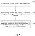
- Fig. 1 is a flowchart of a method for displaying SOC of a battery according to an embodiment of the present disclosure. The method includes the following steps.
- Step 101 an initial voltage and initial SOC of the battery are acquired.
- a state at any time is an initial state, and a voltage at the initial state is the initial voltage.
- an SOC-on voltage during SOC-on of terminal equipment may be selected as an initial voltage, and then a corresponding initial SOC is acquired according to the initial voltage, wherein the initial SOC may be a percentage.
- implementation of a method for acquiring the initial voltage and the initial SOC includes that:
- the preset corresponding relationship between the voltage and the SOC is calculated by multiple sampling.
- Step 102 a current voltage and current SOC of the battery in a current state are acquired after charging or discharging the battery for a preset time.
- the preset time may be one minute or two minutes, and in the embodiment of the present disclosure, the specific time length of the preset time is not limited.
- implementation of a method for acquiring the initial voltage and the initial SOC includes:
- the SOC may be corrected according to a charging and discharging SOC calibration strategy, that is, the step that the current voltage and current SOC of the battery in the current state are acquired after charging for the preset time further includes that: a difference value corresponding to the acquired current voltage is matched according to a preset corresponding relationship between a difference value and a voltage; and correspondingly, Step 302 is further implemented as follows: a current SOC corresponding to the corrected current voltage is acquired according to the preset corresponding relationship between the voltage and the SOC.
- a charging and discharging SOC calibration strategy that is, the step that the current voltage and current SOC of the battery in the current state are acquired after charging for the preset time further includes that: a difference value corresponding to the acquired current voltage is matched according to a preset corresponding relationship between a difference value and a voltage; and correspondingly, Step 302 is further implemented as follows: a current SOC corresponding to the corrected current voltage is acquired according to the preset corresponding relationship between the voltage and the SOC.
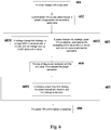
- Fig. 4 is a flowchart of a charging and discharging SOC calibration strategy according to the embodiment. The flow includes:
- Step 103 if the ratio of the current voltage to the initial voltage meets a first preset condition and the ratio of the current SOC to the initial SOC meets a second preset condition, the current voltage and the current SOC are displayed.
- the first preset condition refers to a voltage change limit strategy, and is further that: a rise or drop value of the voltage of the battery within a certain period of time may not exceed a first limit value, and if being exceeded, the first limit value is adopted for calculation, wherein the first limit value is preset.
- the second preset condition refers to an SOC change limit strategy. Specifically, a rise or drop value of SOC of the battery within a certain period of time may not exceed a second limit value, and if being exceeded, the second limit value is adopted for calculation, wherein the second limit value is preset.
- the current voltage and the current SOC are displayed, wherein the current SOC may be a percentage.
- the SOC of the battery is obtained according to a corresponding relationship of voltage and SOC changes of the battery in charging and discharging processes of the battery, so that accurate calculation of the SOC of the battery of a terminal is implemented without an additional hardware circuit such as a voltameter chip, and cost is reduced; and meanwhile, no voltameter chip is required, so that a valuable space on a PCB is saved, and competitiveness of a product is increased.
- the method further includes that: if the acquired current voltage of the battery in the current state meets the first preset condition and the current SOC does not meet the second preset condition, the current SOC of the battery is corrected by virtue of the second preset limit value, and the corrected current SOC is displayed.
- the method further includes that: if the acquired current SOC of the battery in the current state meets the second preset condition and the current voltage does not meet the first preset condition, the current voltage of the battery is corrected by virtue of the first preset limit value.
- the method further includes that: the current SOC and the initial SOC are compared; if the current SOC is smaller than the initial SOC, multiple current SOCs of the battery are continuously acquired according to a preset period; the multiple current SOCs and the initial SOC are compared; and if all the multiple current SOCs are smaller than the initial SOC, the latest current SOC is displayed.
- the method further includes that: the current SOC and the initial SOC are compared; if the current SOC is larger than the initial SOC, multiple current SOCs of the battery are continuously acquired according to a preset period; the multiple current SOCs and the initial SOC are compared; and if all the multiple current SOCs are larger than the initial SOC, the latest current SOC is displayed.
- Fig. 5 is a second flowchart of charging and discharging SOC calibration according to an embodiment of the present disclosure. The flow further includes the following steps.
- the calibration includes:
- the calibration includes:
- Fig. 6 is a first application diagram of a method for displaying SOC of a battery according to an embodiment of the present disclosure. Fig. 6 will be further introduced below.
- Fig. 6 is an application diagram of a battery in a charging stage. In the embodiment, it is set that a rated current of a charger is 1A and capacity of the battery is 1,500mAh. Specific implementation of the application includes the following steps.
- Step 601 an initial voltage 3.6V is acquired.
- acquisition is implemented through a PMIC.
- the calibration includes:
- the standard charger is 1A
- own current consumption of equipment is 0.1A in a charging stage, so that a charging current is 0.9A at this moment.
- Step 605 second charging and discharging SOC calibration is performed.
- the calibration includes:
- a current SOC if being 14%) is smaller than an initial SOC (15%), multiple current SOCs of the battery are continuously acquired according to a preset period; the multiple current SOCs and the initial SOC are compared; and if all the multiple current SOCs are smaller than the initial SOC, the latest current SOC is displayed.
- Fig. 7 is a second application diagram of a method for displaying SOC of a battery according to an embodiment of the present disclosure. Fig. 7 will be introduced below.
- Fig. 7 is an application diagram of a battery during discharging. In the embodiment, it is set that a rated current of a charger is 1A, capacity of the battery is 1,500mAh and current consumption of a user high-load usage simulation scenario is 450mA. Specific implementation is as follows.
- the calibration includes:
- Step 705 second charging and discharging SOC calibration is performed.
- the calibration includes:
- a current SOC if being 16%) is smaller than an initial SOC (15%), multiple current SOCs of the battery are continuously acquired according to a preset period; the multiple current SOCs and the initial SOC are compared; and if all the multiple current SOCs are smaller than the initial SOC, the latest current SOC is displayed.
- the present disclosure further provides a device for displaying the SOC of the battery.
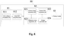
- the device 80 for displaying the SOC of the battery includes: a first acquisition module 81, configured to acquire an initial voltage and initial SOC of the battery.
- a state at any time is an initial state, and a voltage at the initial state is the initial voltage.
- an SOC-on voltage during SOC-on of terminal equipment may be selected as an initial voltage, and then a corresponding initial SOC is acquired according to the initial voltage.
- the first acquisition module 81 includes:
- a second acquisition module 82 is configured to acquire a current voltage and current SOC of the battery in a current state after charging or discharging the battery for a preset time.
- the preset time may be one minute or two minutes, and in the embodiment of the present disclosure, a specific time length of the preset time is not limited.
- the second acquisition module 82 includes:
- the second acquisition module 82 further includes:
- a display module 83 is configured to, if the ratio of the current voltage to the initial voltage meets a first preset condition and the ratio of the current SOC to the initial SOC meets a second preset condition, display the current voltage and the current SOC.
- the first preset condition refers to that: a rise or drop value of a voltage of the battery within a certain period of time may not exceed a first limit value, and if being exceeded, the first limit value is adopted for calculation, wherein the first limit value is preset.
- the second preset condition refers to that: a rise or drop value of SOC of the battery within a certain period of time may not exceed a second limit value, and if being exceeded, the second limit value is adopted for calculation, wherein the second limit value is preset.
- the SOC of the battery is obtained according to a corresponding relationship of voltage and SOC changes of the battery in charging and discharging processes of the battery, so that accurate calculation of the SOC of the battery of a terminal is implemented without an additional hardware circuit such as a voltameter chip, and cost is reduced; and meanwhile, no voltameter chip is used, so that a valuable space on a PCB is saved, and competitiveness of a product is increased.
- the device 80 further includes:
- the embodiment of the present disclosure further provides electronic equipment, which includes the device in embodiment 2.
- the electronic equipment provided by the embodiment of the present disclosure may be a mobile phone, a tablet computer or a digital camera. All embodiments and beneficial effects of the device are applicable to the electronic equipment.
Landscapes
- Physics & Mathematics (AREA)
- General Physics & Mathematics (AREA)
- Engineering & Computer Science (AREA)
- Power Engineering (AREA)
- Secondary Cells (AREA)
- Charge And Discharge Circuits For Batteries Or The Like (AREA)
Description
- The present disclosure relates to the technical field of computers, and more particularly to a method and device for displaying the SOC of a battery, and electronic equipment.
- Intelligent terminal, which is represented by mobile phones, has become increasingly popular, and in the process of using of the intelligent terminal, users also make higher requirements in terms of industrial design, user interface design, application friendliness, security and flows of operating systems, multimedia, self-supporting power consumption and the like.
- In terms of self-supporting power consumption, the power consumption is required to be reduced to improve self-supporting capability on one hand, and on the other hand, the current State-Of-Charge (SOC) and time for self-supporting are also required to be accurately reported to the user to help the user to timely and accurately know about the self-supporting power consumption condition. Generally, SOC calculation is implemented by a voltameter chip. A basic theory is that the SOC of a battery is acquired through voltage acquisition (VADC) and current acquisition (IADC), and the consumed or acquired SOC is acquired according to Q = ∫ I × dt (the SOC in a time period is equal to an integral of current to the time period), thereby a current SOC is obtained.
- In the conventional art, an additional voltameter chip is required to acquire the SOC of a battery. Therefore, cost may be increased on one hand, and on the other hand, the voltameter chip may also occupy a valuable arrangement space on a Printed Circuit Board (PCB).
- The
U.S. Patent Application US 2014/156209 A1 describes devices with battery remaining capacity estimating functions. - The Japanese Patent Application
JP 2003 132959 A - The German Patent Application
DE 199 17 473 A1 describes a technical solution for monitoring battery charge state. - The Chinese
Patent Application CN 102 830 361 A describes a method and a system for quick detection of battery capacity. - Embodiments of the present disclosure provide a method and device for displaying SOC of a battery and electronic equipment, which implement accurate calculation of the SOC of the battery without an additional voltameter chip, saves a valuable arrangement space on a PCB and reduces cost.
- In order to solve the technical problem, the technical solutions of the present disclosure are implemented as defined in the
independent method claim 1, the independent apparatus claim 9, and the corresponding dependent claims. - According to an aspect of the present disclosure, a method for displaying SOC of a battery is provided, which may include that: an initial voltage and initial SOC of the battery are acquired; a current voltage and current SOC of the battery in a current state are acquired after charging or discharging the battery for a preset time; and if the ratio of the current voltage to the initial voltage meets a first preset condition and the ratio of the current SOC to the initial SOC meets a second preset condition, the current voltage and the current SOC are displayed.
- Preferably, the method may further include that: if the first preset condition is met and the second preset condition is not met, the current voltage is utilized as a displayed voltage, and a second limit value is utilized as a displayed SOC.
- Preferably, the method may further include that: if the second preset condition is met and the first preset condition is not met, a first limit value is utilized as the displayed voltage, and the current SOC is utilized as the displayed SOC.
- Preferably, the step that the initial voltage and initial SOC of the battery are acquired may further include that: the initial voltage of the battery is acquired through an SOC Management Integrated Circuit (PMIC); and an initial SOC corresponding to the initial voltage is acquired according to a preset corresponding relationship between a voltage and an SOC.
- Preferably, the step that the current voltage and current SOC of the battery in the current state are acquired after charging or discharging the battery for the preset time may further include that: the current voltage of the battery in the current state is acquired through the PMIC after charging or discharging the battery for the preset time; and a current SOC corresponding to the current voltage is acquired according to the preset corresponding relationship between the voltage and the SOC.
- Preferably, the step that the current voltage and current SOC of the battery in the current state are acquired after charging the battery for the preset time may further include that: a difference value corresponding to the acquired current voltage is matched according to a preset corresponding relationship between a difference value and a voltage; the acquired current voltage is corrected to obtain a corrected current voltage according to the matched difference value; and the step that the current SOC corresponding to the current voltage is acquired according to the preset corresponding relationship between the voltage and the SOC may further be implemented as follows: a current SOC corresponding to the corrected current voltage is acquired according to the preset corresponding relationship between the voltage and the SOC.
- Preferably, in a charging stage of the battery, the method may further include that: the current SOC and the initial SOC are compared; if the current SOC is smaller than the initial SOC, multiple current SOCs of the battery are continuously acquired according to a preset period; the multiple current SOCs with the initial SOC are compared; and if all the multiple current SOCs are smaller than the initial SOC, the latest current SOC is displayed.
- Preferably, in a discharging stage of the battery, the method may further include that: the current SOC and the initial SOC are compared; if the current SOC is larger than the initial SOC, multiple current SOCs of the battery are continuously acquired according to a preset period; the multiple current SOCs and the initial SOC are compared; and if all the multiple current SOCs are larger than the initial SOC, the latest current SOC is displayed.
- According to another aspect of the present disclosure, a device for displaying SOC of a battery is further provided, which may include: a first acquisition module, configured to acquire an initial voltage and initial SOC of the battery; a second acquisition module, configured to acquire a current voltage and current SOC of the battery in a current state after charging or discharging the battery for a preset time; and a display module, configured to, if the ratio of the current voltage to the initial voltage meets a first preset condition and the ratio of the current SOC to the initial SOC meets a second preset condition, display the current voltage and the current SOC.
- Preferably, the device may further include: a voltage correction module, configured to, if the first preset condition is met and the second preset condition is not met, utilize the current voltage as a displayed voltage, and utilize a second limit value as a displayed SOC.
- Preferably, the device may further include: an SOC correction module, configured to, if the second preset condition is met and the first preset condition is not met, utilize a first limit value as the displayed voltage, and utilize the current SOC as the displayed SOC.
- Preferably, the first acquisition module may include: an initial voltage acquisition unit, configured to acquire the initial voltage of the battery through a PMIC; and an initial SOC acquisition unit, configured to acquire an initial SOC corresponding to the initial voltage according to a preset corresponding relationship between a voltage and an SOC.
- Preferably, the second acquisition module may include: a current voltage acquisition unit, configured to acquire the current voltage of the battery in the current state through the PMIC after charging or discharging the battery for the preset time; and a current SOC acquisition unit, configured to acquire a current SOC corresponding to the current voltage according to the preset corresponding relationship between the voltage and the SOC.
- Preferably, the second acquisition module may further include: a difference value acquisition unit, configured to match a difference value corresponding to the acquired current voltage according to a preset corresponding relationship between a difference value and a voltage; a voltage correction unit, configured to correct, according to the matched difference value, the acquired current voltage to obtain a corrected current voltage; and the current SOC acquisition unit may further be configured to acquire a current SOC corresponding to the corrected current voltage according to the preset corresponding relationship between the voltage and the SOC.
- Preferably, in a charging stage of the battery, the device may further include: a charging control module, configured to compare the current SOC with the initial SOC; if the current SOC is smaller than the initial SOC, continuously acquire multiple current SOCs of the battery according to a preset period; compare the multiple current SOCs with the initial SOC; and if all the multiple current SOCs are smaller than the initial SOC, display the latest current SOC.
- Preferably, in a discharging stage of the battery, the device may further include: a discharging control module, configured to compare the current SOC with the initial SOC; if the current SOC is larger than the initial SOC, continuously acquire multiple current SOCs of the battery according to a preset period; compare the multiple current SOCs with the initial SOC; and if all the multiple current SOCs are larger than the initial SOC, display the latest current SOC.
- According to another embodiment of the present disclosure, electronic equipment is further provided, which may include the abovementioned device for displaying the SOC of the battery.
- The present disclosure has the following beneficial effects: the SOC of the battery is obtained according to a corresponding relationship of voltage and SOC changes of the battery in charging and discharging processes of the battery, so that accurate calculation of the SOC of the battery of a terminal is implemented without an additional hardware circuit such as a voltameter chip, and cost is reduced; and meanwhile, no voltameter chip is required, so that a valuable PCB arrangement space in terminal equipment is saved, the cost is further reduced, and a degree of freedom of hardware design and competitiveness of a product are increased.
-
-
Fig. 1 is a flowchart of a method for displaying SOC of a battery according to an embodiment of the present disclosure; -
Fig. 2 is a schematic circuit diagram of acquiring an initial voltage of a battery according to an embodiment of the present disclosure; -
Fig. 3 is a first flowchart of charging and discharging SOC calibration according to an embodiment of the present disclosure; -
Fig. 4 is a flowchart of a charging and discharging SOC calibration strategy according to an embodiment of the present disclosure; -
Fig. 5 is a second flowchart of charging and discharging SOC calibration according to an embodiment of the present disclosure; -
Fig. 6 is a first application diagram of a method for displaying SOC of a battery according to an embodiment of the present disclosure; -
Fig. 7 is a second application diagram of a method for displaying SOC of a battery according to an embodiment of the present disclosure; and -
Fig. 8 is a block diagram of a device for displaying SOC of a battery according to an embodiment of the present disclosure. - Exemplary embodiments of the present disclosure will be described below with reference to the drawings in more detail. Although the exemplary embodiments of the present disclosure are shown in the drawings, it should be understood that the present disclosure may be implemented in various forms and should not be limited by the embodiments elaborated herein. Instead, these embodiments are provided to make the present disclosure understood more thoroughly and completely transmit the scope of the present disclosure to those skilled in the art.
-
Fig. 1 is a flowchart of a method for displaying SOC of a battery according to an embodiment of the present disclosure. The method includes the following steps. - Step 101: an initial voltage and initial SOC of the battery are acquired.
- Preferably, a state at any time is an initial state, and a voltage at the initial state is the initial voltage. In the embodiment of the present disclosure, an SOC-on voltage during SOC-on of terminal equipment may be selected as an initial voltage, and then a corresponding initial SOC is acquired according to the initial voltage, wherein the initial SOC may be a percentage.
- Furthermore, implementation of a method for acquiring the initial voltage and the initial SOC, specifically referring to
Fig. 2 , includes that: - the initial voltage of the battery is acquired through a PMIC;
- an initial SOC corresponding to the initial voltage is acquired according to a preset corresponding relationship between a voltage and SOC.
- Preferably, the preset corresponding relationship between the voltage and the SOC is calculated by multiple sampling.
- Step 102: a current voltage and current SOC of the battery in a current state are acquired after charging or discharging the battery for a preset time.
- Specifically, the preset time may be one minute or two minutes, and in the embodiment of the present disclosure, the specific time length of the preset time is not limited.
- Furthermore, implementation of a method for acquiring the initial voltage and the initial SOC, specifically referring to
Fig. 3 , includes: - Step 301: the current voltage of the battery in the current state is acquired through the PMIC after charging or discharging the battery for the preset time; and
- Step 302: a current SOC corresponding to the current voltage is acquired according to a preset corresponding relationship between a voltage and an SOC, wherein the current SOC may be a percentage.
- In the embodiment, the SOC may be corrected according to a charging and discharging SOC calibration strategy, that is, the step that the current voltage and current SOC of the battery in the current state are acquired after charging for the preset time further includes that: a difference value corresponding to the acquired current voltage is matched according to a preset corresponding relationship between a difference value and a voltage; and correspondingly,
Step 302 is further implemented as follows: a current SOC corresponding to the corrected current voltage is acquired according to the preset corresponding relationship between the voltage and the SOC. - In the embodiment, the corresponding relationship between the difference value and the voltage may be established in the following manner.
Fig. 4 is a flowchart of a charging and discharging SOC calibration strategy according to the embodiment. The flow includes: - Step 401: a voltage-SOC-charging and discharging current corresponding relationship is acquired; and
- Step 402: a difference value-voltage corresponding relationship is obtained according to a condition of increasing a voltage of the battery during charging, and the two corresponding relationships are adopted as basic data for SOC calculation.
- Still refer to
Fig. 1 , Step 103: if the ratio of the current voltage to the initial voltage meets a first preset condition and the ratio of the current SOC to the initial SOC meets a second preset condition, the current voltage and the current SOC are displayed. - Preferably, the first preset condition refers to a voltage change limit strategy, and is further that: a rise or drop value of the voltage of the battery within a certain period of time may not exceed a first limit value, and if being exceeded, the first limit value is adopted for calculation, wherein the first limit value is preset.
- Preferably, the second preset condition refers to an SOC change limit strategy. Specifically, a rise or drop value of SOC of the battery within a certain period of time may not exceed a second limit value, and if being exceeded, the second limit value is adopted for calculation, wherein the second limit value is preset.
- That is, when a current rise value or drop value of the voltage of the battery does not exceed the first limit value and a current rise value or drop value of the SOC of the battery also does not exceed the second limit value, the current voltage and the current SOC are displayed, wherein the current SOC may be a percentage.
- In the embodiment of the present disclosure, the SOC of the battery is obtained according to a corresponding relationship of voltage and SOC changes of the battery in charging and discharging processes of the battery, so that accurate calculation of the SOC of the battery of a terminal is implemented without an additional hardware circuit such as a voltameter chip, and cost is reduced; and meanwhile, no voltameter chip is required, so that a valuable space on a PCB is saved, and competitiveness of a product is increased.
- Furthermore, the method further includes that: if the acquired current voltage of the battery in the current state meets the first preset condition and the current SOC does not meet the second preset condition, the current SOC of the battery is corrected by virtue of the second preset limit value, and the corrected current SOC is displayed.
- Furthermore, the method further includes that: if the acquired current SOC of the battery in the current state meets the second preset condition and the current voltage does not meet the first preset condition, the current voltage of the battery is corrected by virtue of the first preset limit value.
- Furthermore, in a charging stage of the battery, the method further includes that: the current SOC and the initial SOC are compared;
if the current SOC is smaller than the initial SOC, multiple current SOCs of the battery are continuously acquired according to a preset period;
the multiple current SOCs and the initial SOC are compared; and
if all the multiple current SOCs are smaller than the initial SOC, the latest current SOC is displayed. - Furthermore, in a discharging stage of the battery, the method further includes that: the current SOC and the initial SOC are compared;
if the current SOC is larger than the initial SOC, multiple current SOCs of the battery are continuously acquired according to a preset period;
the multiple current SOCs and the initial SOC are compared; and
if all the multiple current SOCs are larger than the initial SOC, the latest current SOC is displayed. -
Fig. 5 is a second flowchart of charging and discharging SOC calibration according to an embodiment of the present disclosure. The flow further includes the following steps. - Step 501: an initial voltage is acquired.
- Step 502: current SOC is calculated through a preset voltage-SOC corresponding relationship.
- Step 503: first charging and discharging SOC calibration is performed.
- Specifically, the calibration includes:
- Step 5031: a voltage change limit strategy: a rise or drop value of a voltage of a battery within a certain period of time may not exceed a first limit value, and if being exceeded, a limit value is adopted for calculation; and
- Step 5032: an SOC change limit strategy: a rise or drop value of SOC of the battery within a certain period of time may not exceed a limit value, and if being exceeded, the limit value is adopted for calculation.
- Step 504: the two strategies are analyzed to obtain a voltage and an SOC.
- Step 505: second charging and discharging SOC calibration is performed.
- Specifically, the calibration includes:
- Step 5051: a charging SOC drop limit strategy: SOC drop is not allowed during charging unless a sampled voltage continuously drops for many times; and
- Step 5052: a discharging SOC rise limit strategy: SOC rise is not allowed during discharging unless the sampled voltage continuously rises for many times.
- Step 506: SOC of the battery is acquired.
-
Fig. 6 is a first application diagram of a method for displaying SOC of a battery according to an embodiment of the present disclosure.Fig. 6 will be further introduced below. -
Fig. 6 is an application diagram of a battery in a charging stage. In the embodiment, it is set that a rated current of a charger is 1A and capacity of the battery is 1,500mAh. Specific implementation of the application includes the following steps. - Step 601: an initial voltage 3.6V is acquired.
- Specifically, acquisition is implemented through a PMIC.
- Step 602:
current SOC 15% is calculated through a preset voltage-SOC corresponding relationship. - Step 603: first charging and discharging calibration is performed, and charging is started.
- Specifically, the calibration includes:
- Step 6031: a voltage change limit strategy: a voltage 3.62V is obtained after a minute, and the voltage rises by 0.02V within a limit value; and
- Step 6032: an SOC change limit strategy:
SOC 17% is obtained at this moment, and rises by 2% exceeding a limit value within a minute, and the limit value is adopted for calculation. - Step 604: the two strategies are analyzed, and the
limit value 1% is adopted for SOC calculation. - Calculation is specifically implemented as follows: in the embodiment, the standard charger is 1A, and it is known that own current consumption of equipment is 0.1A in a charging stage, so that a charging current is 0.9A at this moment. At this moment, SOC rises by (0.9∗1min)/(1.5A∗60min)=0.01, i.e. 1%, within a minute, so that a maximum rise limit within a minute is 5%, and the
SOC 17% obtained inStep 6032 is corrected to be 16%. - Step 605: second charging and discharging SOC calibration is performed.
- Specifically, the calibration includes:
- Step 6051: a charging SOC drop limit strategy: the SOC rises at this moment, and the strategy is not used.
- Step 606: the
SOC 16% of the battery is obtained after a minute. - Furthermore, in the embodiment, if a current SOC (if being 14%) is smaller than an initial SOC (15%), multiple current SOCs of the battery are continuously acquired according to a preset period;
the multiple current SOCs and the initial SOC are compared; and
if all the multiple current SOCs are smaller than the initial SOC, the latest current SOC is displayed. -
Fig. 7 is a second application diagram of a method for displaying SOC of a battery according to an embodiment of the present disclosure.Fig. 7 will be introduced below. -
Fig. 7 is an application diagram of a battery during discharging. In the embodiment, it is set that a rated current of a charger is 1A, capacity of the battery is 1,500mAh and current consumption of a user high-load usage simulation scenario is 450mA. Specific implementation is as follows. - Step 701: an initial voltage 3.6V is acquired.
- Step 702:
current SOC 15% is calculated through a preset voltage-SOC corresponding relationship. - Step 703: first charging and discharging calibration is performed, and discharging is started.
- Specifically, the calibration includes:
- Step 7031: a voltage change limit strategy: a voltage 3.56V is obtained after two minutes, and the voltage drops by 0.04V within a limit value; and
- Step 7032: an SOC change limit strategy:
SOC 13% is obtained at this moment, and drops by 1% exceeding a limit value within a minute, and the limit value is adopted for calculation. - Step 704: the two strategies are analyzed, and the limit value 0.05% is adopted for SOC calculation.
- Calculation is specifically implemented as follows: in the embodiment, the current consumption of the user heavy-load usage simulation scenario is 450mA, and SOC drops by (0.45A∗1min)/(1,5A∗60min)=0.005, i.e. 0.5%, within a minute at this moment. Therefore, a maximum drop limit within a minute is 0.5%, and the
SOC 13% obtained inStep 7032 is corrected to be 14%. - Step 705: second charging and discharging SOC calibration is performed.
- Specifically, the calibration includes:
- Step 7051: a discharging SOC rise limit strategy: the SOC drops at this moment, and the strategy is not used.
- Step 706: the
SOC 14% of the battery is obtained after two minutes. - Furthermore, in the embodiment, if a current SOC (if being 16%) is smaller than an initial SOC (15%), multiple current SOCs of the battery are continuously acquired according to a preset period;
the multiple current SOCs and the initial SOC are compared; and
if all the multiple current SOCs are smaller than the initial SOC, the latest current SOC is displayed. - Corresponding to a method for displaying SOC of a battery in
embodiment 1, the present disclosure further provides a device for displaying the SOC of the battery. - As shown in
Fig. 8 , thedevice 80 for displaying the SOC of the battery includes: afirst acquisition module 81, configured to acquire an initial voltage and initial SOC of the battery. - Preferably, a state at any time is an initial state, and a voltage at the initial state is the initial voltage. In the embodiment of the present disclosure, an SOC-on voltage during SOC-on of terminal equipment may be selected as an initial voltage, and then a corresponding initial SOC is acquired according to the initial voltage.
- Preferably, the
first acquisition module 81 includes: - an initial
voltage acquisition unit 811, configured to acquire the initial voltage of the battery through a PMIC; and - an initial
SOC acquisition unit 812, configured to acquire an initial SOC corresponding to the initial voltage according to a preset corresponding relationship between a voltage and SOC. - A
second acquisition module 82 is configured to acquire a current voltage and current SOC of the battery in a current state after charging or discharging the battery for a preset time. - Preferably, the preset time may be one minute or two minutes, and in the embodiment of the present disclosure, a specific time length of the preset time is not limited.
- Preferably, the
second acquisition module 82 includes: - a current
voltage acquisition unit 821, configured to acquire the current voltage of the battery in the current state through the PMIC after charging or discharging the battery for the pre-set time; and - a current
SOC acquisition unit 822, configured to acquire a current SOC corresponding to the current voltage according to the preset corresponding relationship between the voltage and the SOC. - Furthermore, after charging for the pre-set time, the
second acquisition module 82 further includes: - a difference
value acquisition unit 823, configured to match a difference value corresponding to the acquired current voltage according to a preset corresponding relationship between a difference value and a voltage; - a
voltage correction unit 824, configured to correct, according to the matched difference value, the acquired current voltage to obtain a corrected current voltage; and - the current
SOC acquisition unit 822 is further configured to acquire a current SOC corresponding to the corrected current voltage according to the preset corresponding relationship between the voltage and the SOC. - A
display module 83 is configured to, if the ratio of the current voltage to the initial voltage meets a first preset condition and the ratio of the current SOC to the initial SOC meets a second preset condition, display the current voltage and the current SOC. - Preferably, the first preset condition refers to that: a rise or drop value of a voltage of the battery within a certain period of time may not exceed a first limit value, and if being exceeded, the first limit value is adopted for calculation, wherein the first limit value is preset.
- Preferably, the second preset condition refers to that: a rise or drop value of SOC of the battery within a certain period of time may not exceed a second limit value, and if being exceeded, the second limit value is adopted for calculation, wherein the second limit value is preset.
- In the embodiment of the present disclosure, the SOC of the battery is obtained according to a corresponding relationship of voltage and SOC changes of the battery in charging and discharging processes of the battery, so that accurate calculation of the SOC of the battery of a terminal is implemented without an additional hardware circuit such as a voltameter chip, and cost is reduced; and meanwhile, no voltameter chip is used, so that a valuable space on a PCB is saved, and competitiveness of a product is increased.
- Furthermore, the
device 80 further includes: - a charging control module, configured to compare the current SOC with the initial SOC, if the current SOC is smaller than the initial SOC, continuously acquire multiple current SOCs of the battery according to a preset period,
- compare the multiple current SOCs with the initial SOC, and if all the multiple current SOCs are smaller than the initial SOC, display the latest current SOC; and
- a discharging control module, configured to compare the current SOC with the initial SOC, if the current SOC is larger than the initial SOC, continuously acquire multiple current SOCs of the battery according to a preset period, compare the multiple current SOCs with the initial SOC; and if all the multiple current SOCs are larger than the initial SOC, display the latest current SOC.
- Corresponding to a device in
embodiment 2, the embodiment of the present disclosure further provides electronic equipment, which includes the device inembodiment 2. The electronic equipment provided by the embodiment of the present disclosure may be a mobile phone, a tablet computer or a digital camera. All embodiments and beneficial effects of the device are applicable to the electronic equipment. - The above is the preferred implementation mode of the present disclosure.
Claims (15)
- A method for displaying State-Of-Charge (SOC) of a battery, comprising:acquiring an initial voltage, and acquiring an initial SOC of the battery according to a preset corresponding relationship between a voltage and an SOC;acquiring a current voltage, and a current SOC of the battery in a current state corresponding to the current voltage according to the preset corresponding relationship between the voltage and the SOC after charging or discharging the battery for a preset time; andif a ratio of the current voltage to the initial voltage meets a first preset condition and a ratio of the current SOC to the initial SOC meets a second preset condition, displaying the current voltage and the current SOC,wherein the first preset condition refers to that a rise or drop value of a voltage of the battery within a certain period of time not exceed a first limit value, the second preset condition refers to that a rise or drop value of SOC of the battery within a certain period of time not exceed a second limit value.
- The method according to claim 1, further comprising:
if the first preset condition is met and the second preset condition is not met, utilizing the current voltage meeting the first preset condition as a displayed voltage, and utilizing a second limit value as a displayed SOC. - The method according to claim 1, further comprising:
if the second preset condition is met and the first preset condition is not met, utilizing the current SOC meeting the second preset condition as the displayed SOC, and utilizing a first limit value as the displayed voltage. - The method according to any one of claims 1 to 3, wherein acquiring the initial voltage further comprises:
acquiring the initial voltage of the battery through an SOC Management Integrated Circuit (PMIC). - The method according to any one of claims 1 to 3, wherein acquiring the current voltage after charging or discharging the battery for the preset time further comprises:
acquiring, via a PMIC, the current voltage of the battery in the current state after charging or discharging the battery for the preset time. - The method according to claim 1, wherein acquiring the current voltage and current SOC of the battery in the current state after charging the battery for the preset time further comprises:matching a difference value corresponding to the acquired current voltage according to a preset corresponding relationship between a difference value and a voltage;correcting, according to the matched difference value, the acquired current voltage to obtain a corrected current voltage; andacquiring the current SOC corresponding to the current voltage according to the preset corresponding relationship between the voltage and the SOC comprises:
acquiring the current SOC corresponding to the corrected current voltage according to the preset corresponding relationship between the voltage and the SOC. - The method according to any one of claims 1 to 3, in a charging stage of the battery, further comprising:comparing the current SOC with the initial SOC;if the current SOC is smaller than the initial SOC, continuously acquiring multiple current SOCs of the battery according to a preset period;comparing the multiple current SOCs with the initial SOC; andif all the multiple current SOCs are smaller than the initial SOC, displaying the latest current SOC.
- The method according to any one of claims 1 to 3, in a discharging stage of the battery, further comprising:comparing the current SOC with the initial SOC;if the current SOC is larger than the initial SOC, continuously acquiring multiple current SOCs of the battery according to a preset period;comparing the multiple current SOCs with the initial SOC; andif all the multiple current SOCs are larger than the initial SOC, displaying the latest current SOC.
- A device for displaying State-Of-Charge (SOC) of a battery, comprising:a first acquisition module (81), configured to acquire an initial voltage and initial SOC of the battery;a second acquisition module (82), configured to acquire a current voltage and a current SOC of the battery in a current state corresponding to the current voltage according to the preset corresponding relationship between the voltage and the SOC after charging or discharging the battery for a preset time; anda display module (83), configured to, if a ratio of the current voltage to the initial voltage meets a first preset condition and a ratio of the current SOC to the initial SOC meets a second preset condition, display the current voltage and the current SOC;wherein the first acquisition module (81) comprises:
an initial SOC acquisition unit (812), configured to acquire an initial SOC corresponding to the initial voltage according to a preset corresponding relationship between a voltage and an SOC, wherein the first preset condition refers to that a rise or drop value of a voltage of the battery within a certain period of time not exceed a first limit value, the second preset condition refers to that a rise or drop value of SOC of the battery within a certain period of time not exceed a second limit value. - The device according to claim 9, further comprising:
a voltage correction module (824), configured to, if the first preset condition is met and the second preset condition is not met, utilize the current voltage as a displayed voltage, and utilize a second limit value as a displayed SOC. - The device according to claim 9, further comprising:
an SOC correction module, configured to, if the second preset condition is met and the first preset condition is not met, utilize a first limit value as the displayed voltage, and utilize the current SOC as the displayed SOC. - The device according to any one of claims 9 to 11, wherein the first acquisition module comprises:
an initial voltage acquisition unit (811), configured to acquire the initial voltage of the battery through an SOC Management Integrated Circuit (PMIC). - The device according to any one of claims 9 to 11, wherein the second acquisition module comprises:
a current voltage acquisition unit (821), configured to acquire the current voltage of the battery in the current state through a PMIC after charging or discharging the battery for the preset time. - The device according to claim 9, wherein the second acquisition module further comprises:a difference value acquisition unit (823), configured to match a difference value corresponding to the acquired current voltage according to a preset corresponding relationship between a difference value and a voltage;a voltage correction unit (824), configured to correct, according to the matched difference value, the acquired current voltage to obtain a corrected current voltage; andthe current SOC acquisition unit (812) is further configured to acquire a current SOC corresponding to the corrected current voltage according to the preset corresponding relationship between the voltage and the SOC.
- The device according to any one of claims 9 to 11, in a charging stage of the battery, further comprising:a charging control module, configured to compare the current SOC with the initial SOC; if the current SOC is smaller than the initial SOC, continuously acquire multiple current SOCs of the battery according to a preset period;compare the multiple current SOCs with the initial SOC; and if all the multiple current SOCs are smaller than the initial SOC, display the latest current SOC;and/or in a discharging stage of the battery, further comprising:a discharging control module, configured to compare the current SOC with the initial SOC; if the current SOC is larger than the initial SOC, continuously acquire multiple current SOCs of the battery according to a preset period;compare the multiple current SOCs with the initial SOC; and if all the multiple current SOCs are larger than the initial SOC, display the latest current SOC.
Applications Claiming Priority (2)
| Application Number | Priority Date | Filing Date | Title |
|---|---|---|---|
| CN201410448718.7A CN104297689B (en) | 2014-09-04 | 2014-09-04 | A method, device and electronic equipment for displaying battery power |
| PCT/CN2014/090954 WO2016033868A1 (en) | 2014-09-04 | 2014-11-12 | Method and apparatus for displaying electricity quantity of battery, and electronic device |
Publications (3)
| Publication Number | Publication Date |
|---|---|
| EP3190425A1 EP3190425A1 (en) | 2017-07-12 |
| EP3190425A4 EP3190425A4 (en) | 2017-09-27 |
| EP3190425B1 true EP3190425B1 (en) | 2020-04-08 |
Family
ID=52317492
Family Applications (1)
| Application Number | Title | Priority Date | Filing Date |
|---|---|---|---|
| EP14901225.4A Active EP3190425B1 (en) | 2014-09-04 | 2014-11-12 | Method and apparatus for displaying electricity quantity of battery, and electronic device |
Country Status (5)
| Country | Link |
|---|---|
| US (1) | US10317470B2 (en) |
| EP (1) | EP3190425B1 (en) |
| KR (1) | KR102353446B1 (en) |
| CN (2) | CN104297689B (en) |
| WO (1) | WO2016033868A1 (en) |
Families Citing this family (19)
| Publication number | Priority date | Publication date | Assignee | Title |
|---|---|---|---|---|
| KR101776403B1 (en) * | 2015-10-08 | 2017-09-07 | 현대자동차주식회사 | Method for controlling OBC for eco-friendly vehicle |
| CN105680521B (en) * | 2016-03-23 | 2018-03-23 | 广东欧珀移动通信有限公司 | Charge function detection method, device and the mobile terminal of mobile terminal |
| CN106556801B (en) * | 2016-10-09 | 2019-07-19 | 歌尔科技有限公司 | A kind of method, apparatus and electronic equipment obtaining battery capacity |
| EP3605125B1 (en) * | 2017-03-29 | 2025-01-08 | GS Yuasa International Ltd. | Stored electricity amount estimating device, electricity storage module, stored electricity amount estimating method, and computer program |
| US11181584B2 (en) * | 2017-03-29 | 2021-11-23 | Gs Yuasa International Ltd. | Storage amount estimation device, energy storage module, storage amount estimation method, and computer program |
| CN107356881B (en) * | 2017-07-19 | 2019-11-22 | 广州珅玥软件有限公司 | Terminal control method, device and terminal |
| CN108020790B (en) * | 2017-11-08 | 2020-08-14 | 潍坊歌尔电子有限公司 | Method and device for detecting electric quantity of battery after charging |
| CN109212428A (en) * | 2018-09-20 | 2019-01-15 | 合肥英睿系统技术有限公司 | A kind of electronic product and its electric quantity display system and method |
| ES2784074B2 (en) * | 2019-03-19 | 2021-01-26 | Seat Sa | A method and a monitoring arrangement of an electric energy accumulator |
| KR102819970B1 (en) | 2019-05-03 | 2025-06-13 | 주식회사 엘지에너지솔루션 | Apparatus and method for diagnosing battery cell |
| CN110277817B (en) * | 2019-06-28 | 2023-04-21 | 歌尔科技有限公司 | Electric quantity acquisition method, device and equipment of electronic equipment and storage medium |
| CN110850313A (en) * | 2019-11-14 | 2020-02-28 | 宁波德晶元科技有限公司 | Lithium battery charging and discharging electric quantity display method and system |
| CN113933717B (en) * | 2020-07-14 | 2024-10-25 | 北京小米移动软件有限公司 | Method and device for obtaining electric quantity of battery, battery and electronic equipment |
| CN112345942B (en) * | 2020-11-09 | 2024-02-23 | 阳光储能技术有限公司 | Battery system and BMS (battery management system) and full charge-discharge SOC (system on chip) calibration method thereof |
| CN112531847B (en) * | 2020-12-09 | 2023-07-14 | 上海安酷创新能源有限公司 | A kind of SOC display method, system and electronic equipment of cascaded BMS |
| WO2022257135A1 (en) * | 2021-06-11 | 2022-12-15 | 浙江今日阳光新能源车业有限公司 | Electric quantity display method for electric vehicle, electric vehicle instrument, and computer storage medium |
| CN114076898B (en) * | 2021-11-11 | 2023-09-08 | 深圳市冠旭电子股份有限公司 | Earphone battery electric quantity detection method, device, equipment and storage medium |
| CN115639484A (en) * | 2022-11-01 | 2023-01-24 | 广汽埃安新能源汽车股份有限公司 | Method and device for correcting available battery capacity |
| CN118604638B (en) * | 2024-08-08 | 2024-12-03 | 珠海趣印科技有限公司 | Battery SOC estimation method for thermal printer, and readable storage medium |
Family Cites Families (39)
| Publication number | Priority date | Publication date | Assignee | Title |
|---|---|---|---|---|
| JPH07163058A (en) * | 1993-12-07 | 1995-06-23 | Nec Corp | Battery life notification system |
| JP3390559B2 (en) * | 1995-01-30 | 2003-03-24 | 株式会社日本自動車部品総合研究所 | Battery display device for electric vehicles |
| JPH08320361A (en) * | 1995-05-24 | 1996-12-03 | Sharp Corp | Battery remaining capacity estimation method and battery remaining capacity estimation device |
| JP3454657B2 (en) * | 1997-01-30 | 2003-10-06 | 三洋電機株式会社 | Remaining battery capacity detection method |
| JPH11215725A (en) | 1998-01-29 | 1999-08-06 | Oki Electric Ind Co Ltd | Charge state determination method, charge state determination device, and charging device |
| DE19917473A1 (en) * | 1999-04-17 | 2000-10-19 | Deutsche Telekom Ag | Battery charge state monitor |
| JP3674466B2 (en) | 1999-11-24 | 2005-07-20 | セイコーエプソン株式会社 | Voltage detection device, battery remaining amount detection device, voltage detection method, battery remaining amount detection method, electronic timepiece, and electronic device |
| JP2003132959A (en) * | 2001-10-24 | 2003-05-09 | Matsushita Electric Ind Co Ltd | Deterioration determination method for secondary battery used in power supply system and power supply system using the same |
| JP2004168126A (en) * | 2002-11-19 | 2004-06-17 | Mazda Motor Corp | Vehicle battery capacity detection control device |
| JP4780965B2 (en) * | 2005-01-14 | 2011-09-28 | 三洋電機株式会社 | Battery remaining capacity detection method and power supply device |
| KR101134894B1 (en) * | 2006-06-28 | 2012-04-13 | 엘지전자 주식회사 | Apparatus and method for detecting and displaying the remains of battery capacity |
| CN101153894B (en) * | 2006-09-26 | 2010-09-29 | 鸿富锦精密工业(深圳)有限公司 | Electricity detection method, electric quantity detection system and electronic equipment using the method |
| TWI394971B (en) * | 2008-09-23 | 2013-05-01 | Ind Tech Res Inst | Characteristic tracking method and circuit for a battery |
| CN201360156Y (en) * | 2008-11-25 | 2009-12-09 | 赵建和 | Charging and discharging management system for improving safety and service life of series-connected battery set |
| KR20120018568A (en) * | 2010-08-23 | 2012-03-05 | 삼성모바일디스플레이주식회사 | Apparatus for indicating remaining electric charge of battery and device for power supplying and recharging comprising the same |
| KR101184081B1 (en) * | 2010-09-17 | 2012-09-19 | 한국과학기술원 | Battery Capacity Calculation Device for Electric Moving Bodies |
| CN102998622B (en) * | 2011-09-08 | 2015-12-16 | 珠海格力电器股份有限公司 | Remote controller and battery voltage detection method and device thereof |
| EP2761316A2 (en) * | 2011-09-30 | 2014-08-06 | KPIT Technologies Limited | System and method for battery monitoring |
| CN103064025B (en) * | 2011-10-19 | 2017-03-22 | 北京谊安医疗系统股份有限公司 | Battery electric quantity detection method and device using the same |
| US8854002B2 (en) * | 2011-10-21 | 2014-10-07 | Blackberry Limited | System and method for programming rechargeable battery characteristics |
| US9146280B2 (en) * | 2011-10-26 | 2015-09-29 | Industrial Technology Research Institute | Method and system for estimating a capacity of a battery |
| KR101866772B1 (en) * | 2011-10-28 | 2018-06-19 | 삼성전자주식회사 | Method for gauging remainder of battery on constant-current/constant-voltage charging and apparatus thereof |
| CN102508169B (en) * | 2011-11-07 | 2013-12-11 | 浙江绿源电动车有限公司 | Device and method for obtaining battery capacity |
| KR101863036B1 (en) * | 2011-11-30 | 2018-06-01 | 주식회사 실리콘웍스 | Method for estimating the state of charge of battery and battery management system |
| CN102830361B (en) * | 2012-08-24 | 2015-01-28 | 海能达通信股份有限公司 | Battery capacity quick detection method and battery capacity quick detection system |
| CN104662766B (en) * | 2012-09-21 | 2018-04-10 | 日产自动车株式会社 | Charged state arithmetic unit and charged state operation method |
| KR101384866B1 (en) | 2012-10-24 | 2014-04-21 | 넥스콘 테크놀러지 주식회사 | A revision method power of soc(state of charge) for a lead-acid battery |
| CN103852725B (en) * | 2012-11-30 | 2018-05-01 | 凹凸电子(武汉)有限公司 | For estimating equipment, the method and system of battery remaining power |
| CN103855747B (en) | 2012-12-05 | 2017-02-08 | 凹凸电子(武汉)有限公司 | battery system and battery charging method |
| CN103364735B (en) * | 2013-07-17 | 2015-11-04 | 长沙市博巨兴电子科技有限公司 | The accurate display packing of portable power source battery electric quantity and device |
| US9869724B2 (en) * | 2013-07-24 | 2018-01-16 | Rohm Co., Ltd. | Power management system |
| US20150046105A1 (en) * | 2013-08-09 | 2015-02-12 | Qualcomm Incorporated | Voltage mode fuel gauge |
| CN103605077B (en) * | 2013-10-25 | 2016-01-13 | 小米科技有限责任公司 | Predetermined battery recognition methods, device and electronic equipment |
| US9578601B2 (en) * | 2013-11-12 | 2017-02-21 | Qualcomm Incorporated | Methods and apparatus for reducing modem power based on a present state of charge of battery |
| CN103675701B (en) | 2013-11-29 | 2016-08-24 | 宇龙计算机通信科技(深圳)有限公司 | The method for correcting of a kind of battery dump energy and device |
| CN103809125B (en) * | 2014-02-13 | 2016-06-01 | 清华大学 | The residue loading capacity method of estimation of lithium ion battery and system |
| KR102057320B1 (en) * | 2014-02-14 | 2019-12-18 | 삼성전자주식회사 | Headphone driver reducing pop and click noise and system on chip having the same |
| KR102335217B1 (en) * | 2014-03-05 | 2021-12-03 | 삼성전자 주식회사 | Driving method of application processor and mobile device using current or power consumption |
| US9742217B2 (en) * | 2014-06-13 | 2017-08-22 | Nissan Motor Co., Ltd. | Charge control apparatus and charge control method |
-
2014
- 2014-09-04 CN CN201410448718.7A patent/CN104297689B/en active Active
- 2014-09-04 CN CN201610087762.9A patent/CN105572599B/en not_active Expired - Fee Related
- 2014-11-12 KR KR1020177009017A patent/KR102353446B1/en active Active
- 2014-11-12 EP EP14901225.4A patent/EP3190425B1/en active Active
- 2014-11-12 US US15/508,582 patent/US10317470B2/en active Active
- 2014-11-12 WO PCT/CN2014/090954 patent/WO2016033868A1/en not_active Ceased
Non-Patent Citations (1)
| Title |
|---|
| None * |
Also Published As
| Publication number | Publication date |
|---|---|
| CN105572599A (en) | 2016-05-11 |
| EP3190425A4 (en) | 2017-09-27 |
| US20170285112A1 (en) | 2017-10-05 |
| WO2016033868A1 (en) | 2016-03-10 |
| KR20170048537A (en) | 2017-05-08 |
| CN105572599B (en) | 2019-08-20 |
| KR102353446B1 (en) | 2022-01-19 |
| CN104297689B (en) | 2017-05-24 |
| CN104297689A (en) | 2015-01-21 |
| EP3190425A1 (en) | 2017-07-12 |
| US10317470B2 (en) | 2019-06-11 |
Similar Documents
| Publication | Publication Date | Title |
|---|---|---|
| US10317470B2 (en) | Method and device for displaying SOC of battery, and electronic equipment thereof | |
| EP4002545B1 (en) | Charging/discharging protection circuit, terminal device, and battery discharging control method | |
| US10910870B2 (en) | Charging device and charging method | |
| US8533509B2 (en) | Device and method for controlling secondary battery | |
| CN112448434B (en) | Charging control method and charging control device | |
| CN106537725A (en) | Charging circuit, electronic device using same, and charger | |
| EP3185348B1 (en) | A battery information detection and control method, smart battery,terminal and computer storage medium | |
| CN103208659B (en) | Electronic equipment charging method and electronic equipment | |
| US20100270981A1 (en) | Power source apparatus and secondary battery charge control method | |
| CN103915863B (en) | Terminal unit and method of supplying power to thereof | |
| US20180205236A1 (en) | Method, apparatus and system for controlling charging of a battery module | |
| US20110025272A1 (en) | Charging method, charging device, and battery pack | |
| US11687138B2 (en) | Power supplying system, electronic apparatus, and power supplying method | |
| EP4318867A2 (en) | Portable power supply including can bus | |
| CN112789779B (en) | Charging current adjustment method, device, terminal and computer-readable storage medium | |
| KR20130090136A (en) | Method and apparatus for charging battery | |
| US20140195827A1 (en) | Electronic device with power control function | |
| CN111483318B (en) | Vehicle power supply system management method and device and electronic equipment | |
| US11031799B2 (en) | Power supply management integrated circuit, electronic device, and control method of power supply management integrated circuit | |
| JP2004159382A (en) | Electronics | |
| CN102298435A (en) | Battery module and management method thereof | |
| CN116260209A (en) | SOC display method, pluggable power supply system, device and storage medium | |
| CN115483727A (en) | Power supply control method and related portable electronic device | |
| CN106451641B (en) | A kind of charging chip, terminal device and charging method | |
| CN221552841U (en) | Portable power supply, system and power supply |
Legal Events
| Date | Code | Title | Description |
|---|---|---|---|
| STAA | Information on the status of an ep patent application or granted ep patent |
Free format text: STATUS: THE INTERNATIONAL PUBLICATION HAS BEEN MADE |
|
| PUAI | Public reference made under article 153(3) epc to a published international application that has entered the european phase |
Free format text: ORIGINAL CODE: 0009012 |
|
| STAA | Information on the status of an ep patent application or granted ep patent |
Free format text: STATUS: REQUEST FOR EXAMINATION WAS MADE |
|
| 17P | Request for examination filed |
Effective date: 20170403 |
|
| AK | Designated contracting states |
Kind code of ref document: A1 Designated state(s): AL AT BE BG CH CY CZ DE DK EE ES FI FR GB GR HR HU IE IS IT LI LT LU LV MC MK MT NL NO PL PT RO RS SE SI SK SM TR |
|
| AX | Request for extension of the european patent |
Extension state: BA ME |
|
| A4 | Supplementary search report drawn up and despatched |
Effective date: 20170828 |
|
| RIC1 | Information provided on ipc code assigned before grant |
Ipc: G01R 31/36 20060101AFI20170822BHEP Ipc: H02J 7/00 20060101ALI20170822BHEP |
|
| DAX | Request for extension of the european patent (deleted) | ||
| GRAP | Despatch of communication of intention to grant a patent |
Free format text: ORIGINAL CODE: EPIDOSNIGR1 |
|
| STAA | Information on the status of an ep patent application or granted ep patent |
Free format text: STATUS: GRANT OF PATENT IS INTENDED |
|
| INTG | Intention to grant announced |
Effective date: 20191031 |
|
| GRAS | Grant fee paid |
Free format text: ORIGINAL CODE: EPIDOSNIGR3 |
|
| GRAA | (expected) grant |
Free format text: ORIGINAL CODE: 0009210 |
|
| STAA | Information on the status of an ep patent application or granted ep patent |
Free format text: STATUS: THE PATENT HAS BEEN GRANTED |
|
| AK | Designated contracting states |
Kind code of ref document: B1 Designated state(s): AL AT BE BG CH CY CZ DE DK EE ES FI FR GB GR HR HU IE IS IT LI LT LU LV MC MK MT NL NO PL PT RO RS SE SI SK SM TR |
|
| REG | Reference to a national code |
Ref country code: CH Ref legal event code: EP Ref country code: AT Ref legal event code: REF Ref document number: 1255124 Country of ref document: AT Kind code of ref document: T Effective date: 20200415 |
|
| REG | Reference to a national code |
Ref country code: DE Ref legal event code: R096 Ref document number: 602014063671 Country of ref document: DE |
|
| REG | Reference to a national code |
Ref country code: IE Ref legal event code: FG4D |
|
| REG | Reference to a national code |
Ref country code: NL Ref legal event code: MP Effective date: 20200408 |
|
| REG | Reference to a national code |
Ref country code: LT Ref legal event code: MG4D |
|
| PG25 | Lapsed in a contracting state [announced via postgrant information from national office to epo] |
Ref country code: PT Free format text: LAPSE BECAUSE OF FAILURE TO SUBMIT A TRANSLATION OF THE DESCRIPTION OR TO PAY THE FEE WITHIN THE PRESCRIBED TIME-LIMIT Effective date: 20200817 Ref country code: NO Free format text: LAPSE BECAUSE OF FAILURE TO SUBMIT A TRANSLATION OF THE DESCRIPTION OR TO PAY THE FEE WITHIN THE PRESCRIBED TIME-LIMIT Effective date: 20200708 Ref country code: IS Free format text: LAPSE BECAUSE OF FAILURE TO SUBMIT A TRANSLATION OF THE DESCRIPTION OR TO PAY THE FEE WITHIN THE PRESCRIBED TIME-LIMIT Effective date: 20200808 Ref country code: FI Free format text: LAPSE BECAUSE OF FAILURE TO SUBMIT A TRANSLATION OF THE DESCRIPTION OR TO PAY THE FEE WITHIN THE PRESCRIBED TIME-LIMIT Effective date: 20200408 Ref country code: SE Free format text: LAPSE BECAUSE OF FAILURE TO SUBMIT A TRANSLATION OF THE DESCRIPTION OR TO PAY THE FEE WITHIN THE PRESCRIBED TIME-LIMIT Effective date: 20200408 Ref country code: NL Free format text: LAPSE BECAUSE OF FAILURE TO SUBMIT A TRANSLATION OF THE DESCRIPTION OR TO PAY THE FEE WITHIN THE PRESCRIBED TIME-LIMIT Effective date: 20200408 Ref country code: LT Free format text: LAPSE BECAUSE OF FAILURE TO SUBMIT A TRANSLATION OF THE DESCRIPTION OR TO PAY THE FEE WITHIN THE PRESCRIBED TIME-LIMIT Effective date: 20200408 Ref country code: GR Free format text: LAPSE BECAUSE OF FAILURE TO SUBMIT A TRANSLATION OF THE DESCRIPTION OR TO PAY THE FEE WITHIN THE PRESCRIBED TIME-LIMIT Effective date: 20200709 |
|
| REG | Reference to a national code |
Ref country code: AT Ref legal event code: MK05 Ref document number: 1255124 Country of ref document: AT Kind code of ref document: T Effective date: 20200408 |
|
| PG25 | Lapsed in a contracting state [announced via postgrant information from national office to epo] |
Ref country code: BG Free format text: LAPSE BECAUSE OF FAILURE TO SUBMIT A TRANSLATION OF THE DESCRIPTION OR TO PAY THE FEE WITHIN THE PRESCRIBED TIME-LIMIT Effective date: 20200708 Ref country code: RS Free format text: LAPSE BECAUSE OF FAILURE TO SUBMIT A TRANSLATION OF THE DESCRIPTION OR TO PAY THE FEE WITHIN THE PRESCRIBED TIME-LIMIT Effective date: 20200408 Ref country code: LV Free format text: LAPSE BECAUSE OF FAILURE TO SUBMIT A TRANSLATION OF THE DESCRIPTION OR TO PAY THE FEE WITHIN THE PRESCRIBED TIME-LIMIT Effective date: 20200408 Ref country code: HR Free format text: LAPSE BECAUSE OF FAILURE TO SUBMIT A TRANSLATION OF THE DESCRIPTION OR TO PAY THE FEE WITHIN THE PRESCRIBED TIME-LIMIT Effective date: 20200408 |
|
| PG25 | Lapsed in a contracting state [announced via postgrant information from national office to epo] |
Ref country code: AL Free format text: LAPSE BECAUSE OF FAILURE TO SUBMIT A TRANSLATION OF THE DESCRIPTION OR TO PAY THE FEE WITHIN THE PRESCRIBED TIME-LIMIT Effective date: 20200408 |
|
| REG | Reference to a national code |
Ref country code: DE Ref legal event code: R097 Ref document number: 602014063671 Country of ref document: DE |
|
| PG25 | Lapsed in a contracting state [announced via postgrant information from national office to epo] |
Ref country code: DK Free format text: LAPSE BECAUSE OF FAILURE TO SUBMIT A TRANSLATION OF THE DESCRIPTION OR TO PAY THE FEE WITHIN THE PRESCRIBED TIME-LIMIT Effective date: 20200408 Ref country code: ES Free format text: LAPSE BECAUSE OF FAILURE TO SUBMIT A TRANSLATION OF THE DESCRIPTION OR TO PAY THE FEE WITHIN THE PRESCRIBED TIME-LIMIT Effective date: 20200408 Ref country code: EE Free format text: LAPSE BECAUSE OF FAILURE TO SUBMIT A TRANSLATION OF THE DESCRIPTION OR TO PAY THE FEE WITHIN THE PRESCRIBED TIME-LIMIT Effective date: 20200408 Ref country code: SM Free format text: LAPSE BECAUSE OF FAILURE TO SUBMIT A TRANSLATION OF THE DESCRIPTION OR TO PAY THE FEE WITHIN THE PRESCRIBED TIME-LIMIT Effective date: 20200408 Ref country code: CZ Free format text: LAPSE BECAUSE OF FAILURE TO SUBMIT A TRANSLATION OF THE DESCRIPTION OR TO PAY THE FEE WITHIN THE PRESCRIBED TIME-LIMIT Effective date: 20200408 Ref country code: AT Free format text: LAPSE BECAUSE OF FAILURE TO SUBMIT A TRANSLATION OF THE DESCRIPTION OR TO PAY THE FEE WITHIN THE PRESCRIBED TIME-LIMIT Effective date: 20200408 Ref country code: RO Free format text: LAPSE BECAUSE OF FAILURE TO SUBMIT A TRANSLATION OF THE DESCRIPTION OR TO PAY THE FEE WITHIN THE PRESCRIBED TIME-LIMIT Effective date: 20200408 Ref country code: IT Free format text: LAPSE BECAUSE OF FAILURE TO SUBMIT A TRANSLATION OF THE DESCRIPTION OR TO PAY THE FEE WITHIN THE PRESCRIBED TIME-LIMIT Effective date: 20200408 |
|
| PLBE | No opposition filed within time limit |
Free format text: ORIGINAL CODE: 0009261 |
|
| STAA | Information on the status of an ep patent application or granted ep patent |
Free format text: STATUS: NO OPPOSITION FILED WITHIN TIME LIMIT |
|
| PG25 | Lapsed in a contracting state [announced via postgrant information from national office to epo] |
Ref country code: SK Free format text: LAPSE BECAUSE OF FAILURE TO SUBMIT A TRANSLATION OF THE DESCRIPTION OR TO PAY THE FEE WITHIN THE PRESCRIBED TIME-LIMIT Effective date: 20200408 Ref country code: PL Free format text: LAPSE BECAUSE OF FAILURE TO SUBMIT A TRANSLATION OF THE DESCRIPTION OR TO PAY THE FEE WITHIN THE PRESCRIBED TIME-LIMIT Effective date: 20200408 |
|
| 26N | No opposition filed |
Effective date: 20210112 |
|
| PG25 | Lapsed in a contracting state [announced via postgrant information from national office to epo] |
Ref country code: SI Free format text: LAPSE BECAUSE OF FAILURE TO SUBMIT A TRANSLATION OF THE DESCRIPTION OR TO PAY THE FEE WITHIN THE PRESCRIBED TIME-LIMIT Effective date: 20200408 |
|
| PG25 | Lapsed in a contracting state [announced via postgrant information from national office to epo] |
Ref country code: MC Free format text: LAPSE BECAUSE OF FAILURE TO SUBMIT A TRANSLATION OF THE DESCRIPTION OR TO PAY THE FEE WITHIN THE PRESCRIBED TIME-LIMIT Effective date: 20200408 |
|
| REG | Reference to a national code |
Ref country code: CH Ref legal event code: PL |
|
| PG25 | Lapsed in a contracting state [announced via postgrant information from national office to epo] |
Ref country code: LU Free format text: LAPSE BECAUSE OF NON-PAYMENT OF DUE FEES Effective date: 20201112 |
|
| REG | Reference to a national code |
Ref country code: BE Ref legal event code: MM Effective date: 20201130 |
|
| PG25 | Lapsed in a contracting state [announced via postgrant information from national office to epo] |
Ref country code: CH Free format text: LAPSE BECAUSE OF NON-PAYMENT OF DUE FEES Effective date: 20201130 Ref country code: LI Free format text: LAPSE BECAUSE OF NON-PAYMENT OF DUE FEES Effective date: 20201130 |
|
| PG25 | Lapsed in a contracting state [announced via postgrant information from national office to epo] |
Ref country code: IE Free format text: LAPSE BECAUSE OF NON-PAYMENT OF DUE FEES Effective date: 20201112 |
|
| PG25 | Lapsed in a contracting state [announced via postgrant information from national office to epo] |
Ref country code: TR Free format text: LAPSE BECAUSE OF FAILURE TO SUBMIT A TRANSLATION OF THE DESCRIPTION OR TO PAY THE FEE WITHIN THE PRESCRIBED TIME-LIMIT Effective date: 20200408 Ref country code: MT Free format text: LAPSE BECAUSE OF FAILURE TO SUBMIT A TRANSLATION OF THE DESCRIPTION OR TO PAY THE FEE WITHIN THE PRESCRIBED TIME-LIMIT Effective date: 20200408 Ref country code: CY Free format text: LAPSE BECAUSE OF FAILURE TO SUBMIT A TRANSLATION OF THE DESCRIPTION OR TO PAY THE FEE WITHIN THE PRESCRIBED TIME-LIMIT Effective date: 20200408 |
|
| PG25 | Lapsed in a contracting state [announced via postgrant information from national office to epo] |
Ref country code: MK Free format text: LAPSE BECAUSE OF FAILURE TO SUBMIT A TRANSLATION OF THE DESCRIPTION OR TO PAY THE FEE WITHIN THE PRESCRIBED TIME-LIMIT Effective date: 20200408 |
|
| PG25 | Lapsed in a contracting state [announced via postgrant information from national office to epo] |
Ref country code: BE Free format text: LAPSE BECAUSE OF NON-PAYMENT OF DUE FEES Effective date: 20201130 |
|
| PGFP | Annual fee paid to national office [announced via postgrant information from national office to epo] |
Ref country code: GB Payment date: 20240919 Year of fee payment: 11 |
|
| PGFP | Annual fee paid to national office [announced via postgrant information from national office to epo] |
Ref country code: DE Payment date: 20240925 Year of fee payment: 11 |
|
| PGFP | Annual fee paid to national office [announced via postgrant information from national office to epo] |
Ref country code: FR Payment date: 20250908 Year of fee payment: 12 |