EP3190408A1 - Preprocessing device and analysis system provided with same - Google Patents
Preprocessing device and analysis system provided with same Download PDFInfo
- Publication number
- EP3190408A1 EP3190408A1 EP14901289.0A EP14901289A EP3190408A1 EP 3190408 A1 EP3190408 A1 EP 3190408A1 EP 14901289 A EP14901289 A EP 14901289A EP 3190408 A1 EP3190408 A1 EP 3190408A1
- Authority
- EP
- European Patent Office
- Prior art keywords
- container
- section
- sample
- separation
- preprocessing
- Prior art date
- Legal status (The legal status is an assumption and is not a legal conclusion. Google has not performed a legal analysis and makes no representation as to the accuracy of the status listed.)
- Granted
Links
- 238000007781 pre-processing Methods 0.000 title claims abstract description 146
- 238000004458 analytical method Methods 0.000 title claims abstract description 35
- 238000000926 separation method Methods 0.000 claims abstract description 184
- 238000001914 filtration Methods 0.000 claims abstract description 84
- 230000032258 transport Effects 0.000 claims abstract description 74
- 238000003825 pressing Methods 0.000 claims abstract description 10
- 238000001514 detection method Methods 0.000 claims description 22
- 238000004949 mass spectrometry Methods 0.000 claims description 9
- 239000007788 liquid Substances 0.000 claims description 8
- 239000003153 chemical reaction reagent Substances 0.000 description 52
- 238000009434 installation Methods 0.000 description 52
- 238000013019 agitation Methods 0.000 description 27
- 238000005070 sampling Methods 0.000 description 23
- 230000007246 mechanism Effects 0.000 description 15
- 238000000034 method Methods 0.000 description 13
- 230000008569 process Effects 0.000 description 13
- 238000007789 sealing Methods 0.000 description 9
- 238000000605 extraction Methods 0.000 description 8
- 238000005406 washing Methods 0.000 description 7
- 230000005856 abnormality Effects 0.000 description 5
- 230000004048 modification Effects 0.000 description 5
- 238000012986 modification Methods 0.000 description 5
- 210000004369 blood Anatomy 0.000 description 4
- 239000008280 blood Substances 0.000 description 4
- 238000011045 prefiltration Methods 0.000 description 4
- 239000000126 substance Substances 0.000 description 4
- 230000007723 transport mechanism Effects 0.000 description 4
- 230000002159 abnormal effect Effects 0.000 description 3
- 239000003795 chemical substances by application Substances 0.000 description 3
- 230000003544 deproteinization Effects 0.000 description 3
- 230000000694 effects Effects 0.000 description 3
- -1 polytetrafluoroethylene Polymers 0.000 description 3
- 229920001343 polytetrafluoroethylene Polymers 0.000 description 3
- 239000004810 polytetrafluoroethylene Substances 0.000 description 3
- OKTJSMMVPCPJKN-UHFFFAOYSA-N Carbon Chemical compound [C] OKTJSMMVPCPJKN-UHFFFAOYSA-N 0.000 description 2
- 239000004743 Polypropylene Substances 0.000 description 2
- 229920006243 acrylic copolymer Polymers 0.000 description 2
- 229920002678 cellulose Polymers 0.000 description 2
- 239000001913 cellulose Substances 0.000 description 2
- 238000010586 diagram Methods 0.000 description 2
- 239000003365 glass fiber Substances 0.000 description 2
- 229920006284 nylon film Polymers 0.000 description 2
- 239000002245 particle Substances 0.000 description 2
- 229920001155 polypropylene Polymers 0.000 description 2
- 229920002981 polyvinylidene fluoride Polymers 0.000 description 2
- 210000002966 serum Anatomy 0.000 description 2
- 210000002700 urine Anatomy 0.000 description 2
- NWUYHJFMYQTDRP-UHFFFAOYSA-N 1,2-bis(ethenyl)benzene;1-ethenyl-2-ethylbenzene;styrene Chemical compound C=CC1=CC=CC=C1.CCC1=CC=CC=C1C=C.C=CC1=CC=CC=C1C=C NWUYHJFMYQTDRP-UHFFFAOYSA-N 0.000 description 1
- 229920002943 EPDM rubber Polymers 0.000 description 1
- 229920000181 Ethylene propylene rubber Polymers 0.000 description 1
- 239000004695 Polyether sulfone Substances 0.000 description 1
- VYPSYNLAJGMNEJ-UHFFFAOYSA-N Silicium dioxide Chemical compound O=[Si]=O VYPSYNLAJGMNEJ-UHFFFAOYSA-N 0.000 description 1
- 230000009471 action Effects 0.000 description 1
- 239000003086 colorant Substances 0.000 description 1
- 238000001035 drying Methods 0.000 description 1
- 239000013013 elastic material Substances 0.000 description 1
- 238000005342 ion exchange Methods 0.000 description 1
- 239000003456 ion exchange resin Substances 0.000 description 1
- 229920003303 ion-exchange polymer Polymers 0.000 description 1
- 238000004895 liquid chromatography mass spectrometry Methods 0.000 description 1
- 239000004973 liquid crystal related substance Substances 0.000 description 1
- 239000000463 material Substances 0.000 description 1
- 239000002184 metal Substances 0.000 description 1
- 229920001220 nitrocellulos Polymers 0.000 description 1
- 229920006393 polyether sulfone Polymers 0.000 description 1
- 102000004169 proteins and genes Human genes 0.000 description 1
- 108090000623 proteins and genes Proteins 0.000 description 1
- 239000000741 silica gel Substances 0.000 description 1
- 229910002027 silica gel Inorganic materials 0.000 description 1
- 229920002379 silicone rubber Polymers 0.000 description 1
- 239000004945 silicone rubber Substances 0.000 description 1
Images


Classifications
-
- G—PHYSICS
- G01—MEASURING; TESTING
- G01N—INVESTIGATING OR ANALYSING MATERIALS BY DETERMINING THEIR CHEMICAL OR PHYSICAL PROPERTIES
- G01N30/00—Investigating or analysing materials by separation into components using adsorption, absorption or similar phenomena or using ion-exchange, e.g. chromatography or field flow fractionation
- G01N30/02—Column chromatography
- G01N30/04—Preparation or injection of sample to be analysed
- G01N30/24—Automatic injection systems
-
- G—PHYSICS
- G01—MEASURING; TESTING
- G01N—INVESTIGATING OR ANALYSING MATERIALS BY DETERMINING THEIR CHEMICAL OR PHYSICAL PROPERTIES
- G01N35/00—Automatic analysis not limited to methods or materials provided for in any single one of groups G01N1/00 - G01N33/00; Handling materials therefor
- G01N35/02—Automatic analysis not limited to methods or materials provided for in any single one of groups G01N1/00 - G01N33/00; Handling materials therefor using a plurality of sample containers moved by a conveyor system past one or more treatment or analysis stations
- G01N35/025—Automatic analysis not limited to methods or materials provided for in any single one of groups G01N1/00 - G01N33/00; Handling materials therefor using a plurality of sample containers moved by a conveyor system past one or more treatment or analysis stations having a carousel or turntable for reaction cells or cuvettes
-
- G—PHYSICS
- G01—MEASURING; TESTING
- G01N—INVESTIGATING OR ANALYSING MATERIALS BY DETERMINING THEIR CHEMICAL OR PHYSICAL PROPERTIES
- G01N1/00—Sampling; Preparing specimens for investigation
- G01N1/02—Devices for withdrawing samples
- G01N1/10—Devices for withdrawing samples in the liquid or fluent state
-
- G—PHYSICS
- G01—MEASURING; TESTING
- G01N—INVESTIGATING OR ANALYSING MATERIALS BY DETERMINING THEIR CHEMICAL OR PHYSICAL PROPERTIES
- G01N30/00—Investigating or analysing materials by separation into components using adsorption, absorption or similar phenomena or using ion-exchange, e.g. chromatography or field flow fractionation
- G01N30/02—Column chromatography
- G01N30/04—Preparation or injection of sample to be analysed
- G01N30/06—Preparation
-
- G—PHYSICS
- G01—MEASURING; TESTING
- G01N—INVESTIGATING OR ANALYSING MATERIALS BY DETERMINING THEIR CHEMICAL OR PHYSICAL PROPERTIES
- G01N30/00—Investigating or analysing materials by separation into components using adsorption, absorption or similar phenomena or using ion-exchange, e.g. chromatography or field flow fractionation
- G01N30/02—Column chromatography
- G01N30/26—Conditioning of the fluid carrier; Flow patterns
- G01N30/28—Control of physical parameters of the fluid carrier
- G01N30/36—Control of physical parameters of the fluid carrier in high pressure liquid systems
-
- G—PHYSICS
- G01—MEASURING; TESTING
- G01N—INVESTIGATING OR ANALYSING MATERIALS BY DETERMINING THEIR CHEMICAL OR PHYSICAL PROPERTIES
- G01N30/00—Investigating or analysing materials by separation into components using adsorption, absorption or similar phenomena or using ion-exchange, e.g. chromatography or field flow fractionation
- G01N30/02—Column chromatography
- G01N30/88—Integrated analysis systems specially adapted therefor, not covered by a single one of the groups G01N30/04 - G01N30/86
-
- G—PHYSICS
- G01—MEASURING; TESTING
- G01N—INVESTIGATING OR ANALYSING MATERIALS BY DETERMINING THEIR CHEMICAL OR PHYSICAL PROPERTIES
- G01N35/00—Automatic analysis not limited to methods or materials provided for in any single one of groups G01N1/00 - G01N33/00; Handling materials therefor
- G01N35/02—Automatic analysis not limited to methods or materials provided for in any single one of groups G01N1/00 - G01N33/00; Handling materials therefor using a plurality of sample containers moved by a conveyor system past one or more treatment or analysis stations
- G01N35/04—Details of the conveyor system
-
- G—PHYSICS
- G01—MEASURING; TESTING
- G01N—INVESTIGATING OR ANALYSING MATERIALS BY DETERMINING THEIR CHEMICAL OR PHYSICAL PROPERTIES
- G01N1/00—Sampling; Preparing specimens for investigation
- G01N1/28—Preparing specimens for investigation including physical details of (bio-)chemical methods covered elsewhere, e.g. G01N33/50, C12Q
- G01N1/40—Concentrating samples
- G01N1/405—Concentrating samples by adsorption or absorption
-
- G—PHYSICS
- G01—MEASURING; TESTING
- G01N—INVESTIGATING OR ANALYSING MATERIALS BY DETERMINING THEIR CHEMICAL OR PHYSICAL PROPERTIES
- G01N30/00—Investigating or analysing materials by separation into components using adsorption, absorption or similar phenomena or using ion-exchange, e.g. chromatography or field flow fractionation
- G01N2030/009—Extraction
-
- G—PHYSICS
- G01—MEASURING; TESTING
- G01N—INVESTIGATING OR ANALYSING MATERIALS BY DETERMINING THEIR CHEMICAL OR PHYSICAL PROPERTIES
- G01N30/00—Investigating or analysing materials by separation into components using adsorption, absorption or similar phenomena or using ion-exchange, e.g. chromatography or field flow fractionation
- G01N30/02—Column chromatography
- G01N30/88—Integrated analysis systems specially adapted therefor, not covered by a single one of the groups G01N30/04 - G01N30/86
- G01N2030/8804—Integrated analysis systems specially adapted therefor, not covered by a single one of the groups G01N30/04 - G01N30/86 automated systems
-
- G—PHYSICS
- G01—MEASURING; TESTING
- G01N—INVESTIGATING OR ANALYSING MATERIALS BY DETERMINING THEIR CHEMICAL OR PHYSICAL PROPERTIES
- G01N35/00—Automatic analysis not limited to methods or materials provided for in any single one of groups G01N1/00 - G01N33/00; Handling materials therefor
- G01N2035/00465—Separating and mixing arrangements
- G01N2035/00475—Filters
- G01N2035/00485—Filters combined with sample carriers
-
- G—PHYSICS
- G01—MEASURING; TESTING
- G01N—INVESTIGATING OR ANALYSING MATERIALS BY DETERMINING THEIR CHEMICAL OR PHYSICAL PROPERTIES
- G01N35/00—Automatic analysis not limited to methods or materials provided for in any single one of groups G01N1/00 - G01N33/00; Handling materials therefor
- G01N35/02—Automatic analysis not limited to methods or materials provided for in any single one of groups G01N1/00 - G01N33/00; Handling materials therefor using a plurality of sample containers moved by a conveyor system past one or more treatment or analysis stations
- G01N35/04—Details of the conveyor system
- G01N2035/0439—Rotary sample carriers, i.e. carousels
- G01N2035/0441—Rotary sample carriers, i.e. carousels for samples
-
- G—PHYSICS
- G01—MEASURING; TESTING
- G01N—INVESTIGATING OR ANALYSING MATERIALS BY DETERMINING THEIR CHEMICAL OR PHYSICAL PROPERTIES
- G01N35/00—Automatic analysis not limited to methods or materials provided for in any single one of groups G01N1/00 - G01N33/00; Handling materials therefor
- G01N35/10—Devices for transferring samples or any liquids to, in, or from, the analysis apparatus, e.g. suction devices, injection devices
- G01N2035/1027—General features of the devices
- G01N2035/1048—General features of the devices using the transfer device for another function
- G01N2035/1053—General features of the devices using the transfer device for another function for separating part of the liquid, e.g. filters, extraction phase
Definitions
- the present invention relates to a preprocessing device for collecting a sample extracted by a separation container into a collection container and for preprocessing the sample, and an analysis system provided with the same.
- a preprocessing device For example, at the time of analyzing a component contained in a sample of biological origin, such as whole blood, blood serum, a dried blood spot or urine, analysis is sometimes performed after preprocessing the sample by a preprocessing device.
- the preprocessing is a process of removing a specific component in the sample, which is not necessary for analysis, and extracting a necessary component, or a process of condensing or drying an extracted sample.
- Various structures are conventionally proposed as a preprocessing device for automatically performing such preprocessing (for example, see Patent Document 1).
- Patent Document 1 discloses a structure according to which a plurality of cartridges (separation containers) is held and transported by a common transport mechanism, each cartridge containing a separating agent through which a specific component in a sample is separated.
- the plurality of cartridges is sequentially transported by the transport mechanism to a pressure application mechanism provided at a predetermined position, and samples are extracted by application of pressure by the pressure application mechanism.
- a plurality of receiving containers (collection containers) for receiving extracted liquid from the cartridges is transported, at below the cartridges, by a transport mechanism different from that of the cartridges, and extraction of samples is continuously performed.
- Patent Document 1 JP 2010-60474 A
- the present invention has been made in view of the above circumstances, and its object is to provide a preprocessing device of a more compact structure, and an analysis system provided with the same. Furthermore, the present invention has its object to provide a preprocessing device which is capable of increasing preprocessing efficiency, and an analysis system provided with the same.
- a preprocessing device of the present invention includes a container holding section, a filtration section and a transport section.
- the container holding section holds a plurality of containers including a separation container with a separating layer through which a specific component in a sample is separated and a collection container for collecting a sample extracted by the separating layer.
- the filtration section separates a sample by the separating layer by applying pressure to a sample in the separation container.
- the transport section transports a container held by the container holding section from a predetermined transport position.
- the container holding section holds the plurality of containers in an annular or arch-shaped holding region formed on an outer circumference of the filtration section, and sequentially moves the plurality of containers to the transport position by shifting the plurality of containers in a circumferential direction of the holding region.
- a plurality of containers held in the holding region may be sequentially moved to the transport position and be transported from the transport position by shifting the containers in the circumferential direction.
- Such a holding region is formed to have an annular or arch shape, and a more compact structure may be achieved by securing an installation space for the filtration section in a vacant space at a center portion of the holding region.
- the distance between a plurality of containers held in the holding region and the filtration section may be made relatively small. Accordingly, the time required to transport each container to the filtration section may be reduced, and the preprocessing efficiency may be increased.
- the separation container and the collection container may be installed in the container holding section in a state where the separation container and the collection container are piled up.
- the container holding section may include a rotating section that rotates on a horizontal plane, and a plurality of container racks that can be detachably mounted to the rotating section, each container rack being for holding a plurality of containers.
- a plurality of containers may be held by each of a plurality of container racks which can be detachably mounted to the rotating section.
- each container rack is allowed to be individually mounted to or dismounted from the rotating section. Accordingly, even while processing is performed on a container which is held by one of the container racks, other container racks may be mounted or dismounted and other tasks may be performed, and thus, the preprocessing efficiency may be increased.
- the preprocessing device may further include a detection section configured to detect that a container held by the container holding section is protruded above a predetermined position.
- the position of the separation container and the collection container, which are piled up is easily shifted. Accordingly, by detecting the shift in the containers by the detection section in such a case, an abnormality may be more effectively prevented from occurring at the time of transporting the containers by the transport section.
- the preprocessing device may further include a notification section configured to issue a notification about protrusion in a case where protrusion of a container above the predetermined position is detected by the detection section.
- an analyst who noticed the notification from the notification section may check the state of the containers which are held by the container holding section. Accordingly, preprocessing may be performed after the shift of the containers is surely corrected.
- the preprocessing device may further include a pressing section configured to push a container held by the container holding section into the container holding section in a case where the container is protruded above a predetermined position.
- the container in a case where a container which is held by the container holding section is protruded above the predetermined position due to installation error or the like, the container may be pushed into the container holding section by the pressing section, and the preprocessing may be performed after the shift of the container is surely corrected.
- a plurality of types of separation containers may be held by the container holding section.
- the processing device may further include a storage section configured to store, in association with each other, a type of the separation container and a position of the separation container held by the container holding section, and a selection receiving section configured to receive selection of a type of the separation container.
- the transport section may transport the separation container of a selected type from the container holding section according to correspondence stored in the storage section.
- a separation container which is suitable for an analysis item may be selected, and the separation container may be reliably transported from the container holding section. Accordingly, a wider variety of analysis items may be handled, and also, preprocessing that is most suitable for the selected analysis item may be performed.
- An analysis system of the present invention includes the preprocessing device, a liquid chromatograph into which a sample extracted by the preprocessing device is to be introduced, and a control section configured to automatically control the preprocessing device and the liquid chromatograph in coordination with each other.
- an analysis system of the present invention includes the preprocessing device, a mass spectrometry device into which a sample extracted by the preprocessing device is to be introduced, and a control section configured to automatically control the preprocessing device and the mass spectrometry device in coordination with each other.
- the holding region is formed into an annular or arch shape, and an installation space for the filtration section is secured in a vacant space at the center portion of the holding region, and thus, a more compact structure may be achieved.
- the distance between a plurality of containers held in the holding region and the filtration section may be made relatively small, and thus, the time required to transport each container to the filtration section may be reduced, and the preprocessing efficiency may be increased.
- FIG. 1 is a schematic front view showing an example structure of an analysis system according to an embodiment of the present invention.
- the analysis system includes a preprocessing device 1, a liquid chromatograph (LC) 100, and a mass spectrometry device (MS) 200, and a sample which is subjected to preprocessing by the preprocessing device 1 is sequentially introduced into the LC 100 and the MS 200 and is analyzed. That is, the analysis system according to the present embodiment is structured by connecting a liquid chromatograph mass spectrometry device (LC/MS) to the preprocessing device 1.
- LC/MS liquid chromatograph mass spectrometry device
- such a structure is not restrictive, and one of the LC 100 and the MS 200 may be omitted so that a sample which is subjected to preprocessing by the preprocessing device 1 is introduced into only one of the LC 100 and the MS 200.
- the preprocessing device 1 performs various types of preprocessing, such as sample dispensing, reagent dispensing, agitation, and filtration, on a sample of biological origin, such as whole blood, blood serum, a dried blood spot, or urine.
- a sample extracted by such preprocessing is introduced into the LC 100 through an autosampler 101 which is provided to the LC 100.
- the LC 100 is provided with a column (not shown), and sample components separated in the process of the sample passing through the column are sequentially introduced into the MS 200.
- the MS 200 includes an ionization section 201 for ionizing a sample introduced from the LC 100, and a mass spectrometry section 202 for analyzing an ionized sample.
- the preprocessing device 1 is provided with an operation display section 1a including a touch panel, for example.
- An analyst is allowed to perform input regarding operation of the preprocessing device 1 by performing operation on a display screen of the operation display section 1a, and is also allowed to check information about operation of the preprocessing device 1 displayed on the display screen of the operation display section 1a.
- the structure where the operation display section 1a of a touch panel type is provided is not restrictive, and a display section structured by a liquid crystal display, and an operation section structured by operation keys or the like may be separately provided.
- FIG. 2 is a plan view showing an example structure of the preprocessing device 1.
- the preprocessing device 1 uses one preprocessing kit, which is a set of a separation container 50 and a collection container 54, for each sample, and performs a preprocessing item (sample dispensing, reagent dispensing, agitation, filtration, etc.) set for each preprocessing kit.
- the preprocessing device 1 is provided with a plurality of processing ports for performing respective preprocessing items, and by installing a preprocessing kit containing a sample in one of the processing ports, the preprocessing item corresponding to the processing port is performed on the sample contained in the preprocessing kit.
- processing ports 30 As the processing ports, filtration ports 30, a dispensing port 32, a discard port 34, agitation ports 36a, temperature adjustment ports 38, 40, a transfer port 43, a washing port 45 and the like are provided in correspondence with the preprocessing items. These processing ports form a plurality of preprocessing sections for performing a plurality of preprocessing items.
- the preprocessing items here are types of preprocessing necessary to analyze analysis items specified by an analyst.
- the separation container 50 and the collection container 54 forming the preprocessing kit is transported between the processing ports by a transport arm 24 as a transport section.
- a holding section 25 for holding the separation container 50 and the collection container 54 is formed on a tip end side of the transport arm 24.
- a base end portion side of the transport arm 24 is rotatably held around a vertical shaft 29.
- the transport arm 24 extends in a horizontal direction, and moves in such a way that the holding section 25 draws an arch on a horizontal plane when the transport arm 24 rotates around the vertical shaft 29.
- Each of the processing ports and other ports, which are transport destinations of the separation container 50 and the collection container 54, are all provided on the arch-shaped track which is drawn by the holding section 25.
- a sample is dispensed into the preprocessing kit from a sample container 6.
- a plurality of sample containers 6 containing samples may be installed in a sample installation section 2, and samples are sequentially collected from the sample containers 6 by a sampling arm 20 as a sampling section.
- a plurality of sample racks 4 for holding a plurality of sample containers 6 are installed next to one another in a circle at the sample installation section 2.
- the sample installation section 2 rotates on the horizontal plane to move the sample racks 4 in a circumferential direction.
- the sample containers 6 may thus be sequentially moved to a predetermined sampling position.
- the sampling position here is on the track of a sampling nozzle 20a provided at a tip end portion of the sampling arm 20, and a sample is collected from the sample container 6 by the sampling nozzle 20a at the sampling position.
- the sampling arm 20 is capable of rotating on the horizontal plane, around a vertical shaft 22 provided on a base end portion side, and of moving up and down in a vertical direction along the vertical shaft 22.
- the sampling nozzle 20a is held at the tip end portion of the sampling arm 20, facing downward in the vertical direction, and moves according to operation of the sampling arm 20 so as to draw an arch on the horizontal plane or to move up and down in the vertical direction.
- the dispensing port 32 is provided on the track of the sampling nozzle 20a, at a position on the track of the holding section 25 of the transport arm 24.
- the dispensing port 32 is a port for dispensing a sample into an unused separation container 50 from the sampling nozzle 20a.
- An unused separation container 50 is transported to the dispensing port 32 by the transport arm 24.
- a reagent installation section 8 for installing reagent containers 10 is provided at a center portion of the sample installation section 2 where the sample racks 4 are arranged next to one another in a circle.
- a reagent in the reagent container 10 installed in the reagent installation section 8 is collected by a reagent arm 26.
- the reagent arm 26 has its base end portion supported by the vertical shaft 29, which is common with that of the transport arm 24, and is capable of rotating on the horizontal plane around the vertical shaft 29, and of moving up and down in the vertical direction along the vertical shaft 29.
- a reagent addition nozzle 26a is held at a tip end portion of the reagent arm 26, facing downward in the vertical direction, and the reagent addition nozzle 26a moves according to operation of the reagent arm 26 so as to draw the same arch as the holding section 25 of the transport arm 24 on the horizontal plane or to move up and down in the vertical direction.
- the reagent installation section 8 is capable of rotating on the horizontal plane independently of the sample installation section 2.
- a plurality of reagent containers 10 is arranged next to one another in a circle at the reagent installation section 8, and each reagent container 10 moves in the circumferential direction when the reagent installation section 8 is rotated.
- a desired reagent container 10 may thereby be moved to a predetermined reagent collection position.
- the reagent collection position is on the track of the reagent addition nozzle 26a provided at the tip end portion of the reagent arm 26, and a reagent is collected by the reagent addition nozzle 26a from the reagent container 10 at the reagent collection position.
- a reagent in the reagent container 10 is sucked into the reagent addition nozzle 26a, and is then dispensed into the separation container 50 installed at the dispensing port 32, and is thus added to the sample in the separation container 50.
- the separation container 50 and the collection container 54 are held by a container holding section 12 provided at a different position from the sample installation section 2 and the reagent installation section 8.
- a plurality of preprocessing kits each of which is a set of unused separation container 50 and collection container 54 that are piled up, are arranged next to one another in a circle at the container holding section 12.
- the container holding section 12 is provided with a rotating section 14, which rotates on the horizontal plane, and a plurality of container racks 16 which is detachably mounted to the rotating section 14.
- Each container rack 16 is capable of holding a plurality of preprocessing kits.
- the plurality of container racks 16 are arranged next to one another in a circle on the rotating section 14.
- An annular holding region for holding a plurality of preprocessing kits is formed by the plurality of container racks 16 arranged next to one another in a circle.
- the rotating section 14 rotates on the horizontal plane to thereby shift each container rack 16 in the circumferential direction of the holding region.
- a plurality of preprocessing kits may thereby be sequentially moved to a predetermined transport position.
- the transport position here is on the track of the holding section 25 provided at the tip end portion of the transport arm 24, and the separation container 50 or the collection container 54 is held by the holding section 25 at the transport position to be transported to a transport destination port.
- each container rack 16 is allowed to be individually mounted to or dismounted from the rotating section 14. Accordingly, even while processing is performed on the separation container 50 or the collection container 54 which is held by one of the container racks 16, other container racks 16 may be mounted or dismounted and other tasks may be performed, and thus, the preprocessing efficiency may be increased.
- the separation container 50 and the collection container 54 do not necessarily have to be held by the container holding section 12 through the container rack 16, and may alternatively be held directly by the container holding section 12, for example. Also, the separation container 50 and the collection container 54 do not necessarily have to be held by the container holding section 12 in a state where they are piled up, and the separation container 50 and the collection container 54 may alternatively be held separately from each other. Moreover, the plurality of container racks 16 do not necessarily have to be arranged next to one another in a circle, and may alternatively be arranged next to one another in an arch, for example. In this case, a plurality of separation containers 50 and collection containers 54 are held in an arch-shaped holding region instead of an annular holding region.
- An analyst may install, at the container holding section 12, a plurality of types (for example, two types) of separation containers 50 with separating layers of different separation performances. These separation containers 50 are used according to the sample analysis items, and a separation container 50 corresponding to the analysis item specified by the analyst is selected and transported from the container holding section 12.
- the analysis item here is the type of analysis which is to be sequentially performed using a sample which has been subjected to preprocessing by the preprocessing device 1, and is the type of analysis to be performed by the LC 100 or the MS 200, for example.
- FIG. 3A is a side view showing an example structure of the separation container 50.
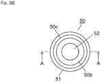
- FIG. 3B is a plan view of the separation container 50 in FIG. 3A .
- FIG. 3C is a cross-sectional view showing a cross-section along A-A in FIG. 3B .
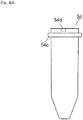
- FIG. 4A is a side view showing an example structure of the collection container 54.
- FIG. 4B is a plan view of the collection container 54 in FIG. 4A .
- FIG. 4C is a cross-sectional view showing a cross-section along B-B in FIG. 4B .
- FIG. 5 is a cross-sectional view showing a preprocessing kit in a state where the separation container 50 and the collection container 54 are piled up.
- the separation container 50 is a cylindrical container having an inner space 50a for containing a sample or a reagent.
- a separating layer 52 is provided at a bottom portion of the inner space 50a.
- the separating layer 52 is a separating agent or a separating film having a function of selectively separating a specific component in a sample by letting a sample pass through and by physically or chemically reacting with the specific component, for example.
- ion exchange resin silica gel, cellulose, or activated carbon
- a polytetrafluoroethylene (PTFE) film a nylon film, a polypropylene film, a polyvinylidene difluoride film (PVDF) film, an acrylic copolymer film, a mixed cellulose film, a nitrocellulose film, a polyethersulfone film, an ion exchange film, or a glass fiber film may be used, for example.
- PTFE polytetrafluoroethylene
- PVDF polyvinylidene difluoride film
- acrylic copolymer film a mixed cellulose film
- nitrocellulose film a polyethersulfone film
- an ion exchange film a glass fiber film
- a deproteinization filter for removing protein in a sample by filtration
- a PTFE or acrylic copolymer film may be used, for example.
- a pre-filter (not shown) may be provide on an upper side of the separating layer 52.
- a nylon film, a polypropylene film, or a glass fiber film may be used, for example.
- the pre-filter is for removing insoluble substances and foreign substances with relatively large particle diameters from a sample.
- the deproteinization filter may be prevented, by this pre-filter, from being clogged with insoluble substances and foreign substances with relatively large particle diameters.
- An opening 50b for injecting a sample or a reagent is formed at an upper surface of the separation container 50.
- an extraction opening 50d for extracting a sample which has passed through the separating layer 52 is formed at a lower surface of the separation container 50.
- a flange section 50c for engaging with the holding section 25 of the transport arm 24 is formed at an upper portion of an outer circumferential surface of the separation container 50, protruding in the circumferential direction.
- a skirt section 51 which contacts the edge of the filtration port 30 when the separation container 50 is accommodated, together with the collection container 54, in the filtration port 30 is provided at a center portion of the outer circumferential surface of the separation container 50.
- the skirt section 51 is formed to have an L shape in cross-section, and protrudes in the circumferential direction from the outer circumferential surface of the separation container 50 and extends downward, and thereby forms a certain space to the outer circumferential surface of the separation container 50.
- the collection container 54 is a cylindrical container for accommodating a lower portion of the separation container 50, and for collecting a sample extracted from the extraction opening 50d of the separation container 50.
- An opening 54b for inserting the lower portion of the separation container 50 is formed to an upper surface of the collection container 54.
- An inner space 54a for accommodating a part of the separation container 50 lower than the skirt section 51 is formed inside the collection container 54.
- a flange section 54c for engaging with the holding section 25 of the transport arm 24 is formed at an upper portion of an outer circumferential surface of the collection container 54, protruding in the circumferential direction.
- the upper portion of the collection container 54 is placed inside the skirt section 51.
- the outer diameter of the separation container 50 is smaller than the inner diameter of the collection container 54. Accordingly, a small gap is formed between the outer circumferential surface of the separation container 50 accommodated in the inner space 54a of the collection container 54 and the inner circumferential surface of the collection container 54.
- the separation container 50 and the collection container 54 are installed in the container holding section 12 with the lower portion of the separation container 50 accommodated inside the collection container 54 (the state shown in FIG. 5 ).
- Three cut-outs 54d are formed to the edge of the upper surface of the collection container 54. Accordingly, when the separation container 50 and the collection container 54 are piled up as shown in FIG. 5 , the inside and the outside of the collection container 54 may be communicated through the cut-outs 54 even in a state where the upper surface of the collection container 54 is in contact with the inner surface of the skirt section 51. Additionally, the number of cut-outs 54d is not limited to three, and it may be two or less, or four or more. Also, a small hole may be formed instead of the cut-out 54d.
- the filtration ports 30 are provided on the inside the container holding section 12. That is, an annular or arch-shaped holding region is formed by the plurality of container racks 16 arranged next to one another on the outer circumference of the filtration ports 30, and a plurality of separation containers 50 and collection containers 54 are held in the holding region. In this manner, because the holding region of the separation containers 50 and the collection containers 54 is formed into an annular or arch shape, and an installation space for the filtration ports 30 is secured in a vacant space at the center portion of the holding region, a more compact structure may be achieved.
- the separation container 50 and the collection container 54 are held in the holding region in a state where they are piled up, separate holding regions do not have to be provided for the separation container 50 and the collection container 54. Therefore, a greater number of separation containers 50 and collection containers 54 may be held in a small holding region. Accordingly, the holding region for the separation containers 50 and the collection containers 54 may be made even smaller, and a more compact structure may be achieved.
- the filtration ports 30 at the center portion of the holding region which is formed into an annular or arch shape, the distances between the plurality of separation containers 50 and collection containers 54 held in the holding region and the filtration ports 30 may be made relatively small. Accordingly, the time required to transport the separation container 50 and the collection container 54 to the filtration port 30 may be reduced, and the preprocessing efficiency may be increased.
- the filtration port 30 forms a filtration section for separating a sample by the separating layer 52 by applying pressure to a sample in the separation container 50.
- two filtration ports 30 are provided next to each other on the track of the holding section 25 of the transport arm 24, for example.
- the separation container 50 and the collection container 54 are installed in each filtration port 30 in a state where they are piled up as shown in FIG. 5 , and a sample separated by the separating layer 52 in the separation container 50 by a negative pressure is collected by the collection container 54.
- the separation container 50 and the collection container 54 do not necessarily have to be installed in the filtration port 30 in a state where they are piled up, and the separation container 50 and the collection container 54 may alternatively be installed separately.
- the number of the filtration ports 30 is not limited to two, and it may be one or three or more.
- Three agitation ports 36a are provided to an agitation section 36 provided near the container holding section 12, next to one another on the track of the holding section 25 of the transport arm 24, for example.
- the agitation section 36 has a mechanism for periodically and separately operating each of the agitation ports 36a on the horizontal plane.
- a sample in the separation container 50 disposed in each agitation port 36a may by agitated by such a mechanism.
- the number of the agitation ports 36a is not limited to three, and it may be two or less, or four or more.
- the temperature adjustment port 38, 40 is provided to a thermally conductive block temperature of which is controlled by a heater and a Peltier device, for example, and the temperature of the separation container 50 or the collection container 54 accommodated in the temperature adjustment port 38, 40 is adjusted to a certain temperature.
- the temperature adjustment port 38 is for the separation container 50, and four temperature adjustment ports 38 are arranged next to one another on the track of the holding section 25 of the transport arm 24, for example.
- the temperature adjustment port 40 is for the collection container 54, and like the temperature adjustment ports 38 for the separation containers 50, four temperature adjustment ports 40 are arranged next to one another on the track of the holding section 25 of the transport arm 24, for example. Additionally, the number of the temperature adjustment ports 38, 40 is not limited to four, and it may be three or less, or five or more.
- FIG. 6A is a plan view showing an example structure of the filtration port 30.
- FIG. 6B is a cross-sectional view showing a cross-section along X-X in FIG. 6A .
- FIG. 6C is a cross-sectional view showing a cross-section along Y-Y in FIG. 6A .
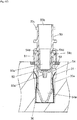
- FIG. 6D is a cross-sectional view showing a state where the preprocessing kit is installed in the filtration port 30.
- the filtration port 30 is formed as a recessed section, for example, and the recessed section forms an installation space 30a for installing the preprocessing kit. That is, as shown in FIG. 6D , the separation container 50 and the collection container 54 transported by the transport arm 24 from the container holding section 12 are installed in the installation space 30a in a state where they are piled up. At this time, the collection container 54 is accommodated first in the installation space 30a, and then, the lower portion of the separation container 50 is accommodated in the inner space 54a of the collection container 54.
- a holding member 31 for sandwiching and holding the collection container 54 is provided inside the filtration port 30.
- the holding member 31 is a U-shaped metal member which is open at the top, for example, and two arm sections extending upward form two leaf springs which are capable of elastically shifting in an inner diameter direction of the filtration port 30.
- the two leaf spring portions of the holding member 31 are curved or bent inward in such a way that the gap between the two is the smallest at a part between upper end portions and lower end portions, for example.
- the gap between the two leaf spring portions is greater than the outer diameter of the collection container 54 at the upper end portions and the lower end portions, and smaller than the outer diameter of the collection container 54 at the part where the gap is the smallest.
- the holding member 31 Due to the shape of the holding member 31 as described above, when the collection container 54 is inserted into the installation space 30a of the filtration port 30, the two leaf spring portions of the holding member 31 are opened as the collection container 54 is lowered, and the collection container 54 is held in the installation space 30a by the elastic force.
- the collection container 54 is equally pressed from two opposite directions by the two leaf spring portions of the holding member 31, and is held at a center portion of the installation space 30a.
- the holding member 31 is fixed inside the installation space 30a, and is prevented from being lifted together with the collection container 54 at the time of removal of the collection container 54.
- a ring-shaped sealing member 60 having elasticity is provided at an edge of an opening section at an upper surface of the filtration port 30.
- the sealing member 60 is fitted in a pit provided at the edge of the opening section at the upper surface of the filtration port 30, for example.
- the material of the sealing member 60 is an elastic material such as silicone rubber or ethylene propylene rubber (EPDM), for example.
- EPDM ethylene propylene rubber
- the contact portion of the separation container 50 to the sealing member 60 is not limited to a member having the shape of the skirt section 51, and contact sections having various shapes, such as a flange section, are allowed, for example.
- a channel 56 for reducing pressure communicates with the installation space 30a from a bottom surface of the filtration port 30.
- a channel 57 of a negative pressure application mechanism 55 is connected to the channel 56.
- the negative pressure application mechanism 55 includes a vacuum pump, for example, and forms a negative pressure application section which applies a negative pressure inside the installation space 30a.
- the inner space 54a of the collection container 54 communicates with the installation space 30a with negative pressure through the cut-outs 54d of the collection container 54 and the gap between the inner circumferential surface of the collection container 54 and the outer circumferential surface of the separation container 50.
- the upper surface of the separation container 50 is open to the atmosphere, and thus, a pressure difference is caused between the inner space 50a of the separation container 50 and the inner space 54a of the collection container 54 across the separating layer 52. Accordingly, only the component, of a sample contained in the inner space 50a of the separation container 50, which can pass through the separating layer 52 is separated by the separating layer 52 by the pressure difference, and is extracted into the inner space 54a side of the collection container 54.
- FIG. 7 is a schematic view showing an example structure of the negative pressure application mechanism 55.
- Two filtration ports 30 are connected to a common vacuum tank 66.
- Each filtration port 30 and the vacuum tank 66 are connected by the channel 57, and a pressure sensor 62 and a three-way valve 64 are provided to each channel 57.
- the pressure inside the installation space 30a of each filtration port 30 is detected by the pressure sensor 62.
- Each three-way valve 64 is capable of switching to any one of a state where the filtration port 30 and the vacuum tank 66 are connected, a state where the channel 57 is open to the atmosphere on the side of the filtration port 30 (the state shown in FIG. 7 ), and a state where an end portion of the channel 57 on the side of the filtration port 30 is sealed.
- a pressure sensor 68 is connected to the vacuum tank 66, and also, a vacuum pump 58 is connected to the vacuum tank 66 through a three-way valve 70. Accordingly, by switching the three-way valve 70, the vacuum pump 58 may be connected to the vacuum tank 66 as necessary to adjust the pressure inside the vacuum tank 66.
- the filtration port 30 and the vacuum tank 66 are connected, and the value of the pressure sensor 62 detecting the pressure inside the installation space 30a of the filtration port 30 is adjusted to be a predetermined value. Then, an end portion of the channel 57 on the side of the filtration port 30 is sealed. The installation space 30a of the filtration port 30 thereby becomes a sealed system, and extraction of a sample is performed by the inside of the installation space 30a being maintained in the reduced pressure state.
- the preprocessing device 1 is provided with a sample transfer section 42 for transferring a sample extracted into the collection container 54 to the autosampler 101 side.
- the sample transfer section 42 includes a moving section 44 which moves in one direction (an arrow direction in FIG. 2 ) on the horizontal plane, and a transfer port 43 for installing the collection container 54 is provided on an upper surface of the moving section 44.
- the moving section 44 moves by operation of a drive mechanism including a rack and pinion mechanism, for example.
- the transfer port 43 is arranged on the track of the holding section 25 of the transport arm 24 (the position shown by a solid line in FIG. 2 ). Installation of the collection container 54 in the transfer port 43 by the transport arm 24, and collection of the collection container 54 from the transfer port 43 are performed in this state.
- the collection container 54 containing the extracted sample is installed in the transfer port 43, and then, the moving section 44 moves in an outward direction of the preprocessing device 1, and the transfer port 43 is arranged at a position adjacent to the autosampler 101 (the position shown by a broken line in FIG. 2 ).
- the sample inside the collection container 54 is sucked in, in this state, by a nozzle for sampling provided to the autosampler 101.
- the moving section 44 is returned to the original position (the position shown by the solid line in FIG. 2 ), and the collection container 54 is collected by the transport arm 24.
- the used collection container 54 is transported to the discard port 34 by the transport arm 24, and is discarded.
- the discard port 34 is arranged near the dispensing port 32, on the track of the holding section 25 of the transport arm 24, and used separation containers 50 and collection containers 54 are discarded.
- the washing port 45 for washing the sampling nozzle 20a is provided on the track of the sampling nozzle 20a. Additionally, although not shown, a washing port for washing the reagent addition nozzle 26a is provided on the track of the reagent addition nozzle 26a.
- FIG. 8 is a side view showing an example structure of the container holding section 12.
- a detection arm 18 is provided to the container holding section 12.
- the detection arm 18 extends in the horizontal direction from the center portion side of the container holding section 12 to the outer side in the radial direction.
- the detection arm 18 is arranged at a position slightly higher (by about 0.3 mm to 0.5 mm, for example) than the upper surface of the separation container 50 when the preprocessing kit is normally installed in the container holding section 12.
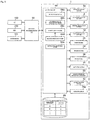
- FIG. 9 is a block diagram showing an example of an electrical configuration of the analysis system.
- a "port" means one of a plurality of types of ports where the separation container 50 or the collection container 54 is to be installed, such as the filtration port 30, the dispensing port 32, the agitation port 36a, the temperature adjustment port 38, 40, or the transfer port 43.
- control section 84 includes a central processing unit (CPU), for example, and functions of preprocessing means 84a, processing status management means 84b, random access means 84c, selection receiving means 84d, notification processing means 84e and the like are realized by the CPU executing programs.
- CPU central processing unit
- An arithmetic processing device 90 configured by a personal computer (PC) or a dedicated computer, for example, is connected to the control section 84, and an analyst may manage the preprocessing device 1 by the arithmetic processing device 90.
- the LC 100 and the MS 200 for performing analysis of a sample which has been subjected to preprocessing by the preprocessing device 1, the autosampler 101 for injecting a sample into the LC 100, and the like are connected to the arithmetic processing device 90, in addition to the preprocessing device 1, and these devices may be automatically controlled in coordination with one another by the arithmetic processing device 90.
- a plurality of sample containers is installed in the sample installation section 2, and samples contained in these sample containers are sequentially dispensed into the separation containers 50, and the separation containers 50 are transported to ports corresponding to the preprocessing items to be performed on the samples.
- the preprocessing means 84a performs a predetermined process corresponding to the port when the separation container 50 or the collection container 54 is installed in each port.
- the random access means 84c checks the status of preprocessing at each port, and controls the operation of the transport arm 24 so that a separation container 50 preprocessing of which at a port is completed is transported to a port where next preprocessing is to be performed. That is, the random access means 84c checks the preprocessing items to be performed next on each sample, checks the vacancy status of the port corresponding to the preprocessing item, and if there is vacancy, the separation container 50 or the collection container 54 containing the sample is transported to the port. Also, if the port corresponding to the preprocessing item to be performed next on a sample is not vacant, the random access means 84c causes the target separation container 50 or collection container 54 to be transported to the port as soon as the port becomes vacant.
- the processing status management means 84b manages the vacancy status of each port and the processing status at each port.
- the vacancy status of each port may be managed by memorizing the port where the separation container 50 or the collection container 54 was installed.
- a sensor for detecting whether the separation container 50 or the collection container 54 is installed in each port or not may be provided, and the vacancy status of each port may be managed based on a signal from the sensor.
- the processing status at each port may be managed based on whether a time required for preprocessing which is being performed at a port has passed since installation of the separation container 50 or the collection container 54 in the port.
- the status of processing at the transfer port 43 may be managed based on whether a signal indicating that sample suction has ended is received from the autosampler 101 side or not.
- two filtration ports 30, three agitation ports 36a, four temperature adjustment ports 38, and four temperature adjustment ports 40, and ports which perform the same preprocessing are prioritized, and the random access means 84c is configured to use ports from one with the highest priority. For example, at the time of performing filtration of a sample, if both of the two filtration ports 30 are vacant, the collection container 54 is installed in the filtration port 30 with higher priority, and the separation container 50 is installed on the collection container 54.
- a storage section 86 configured by a random access memory (RAM) or a hard disk, for example, is capable of storing, in association with each other, the type of a separation container 50 and the position of the separation container 50 held in the container holding section 12. Such correspondence may be set in advance by an analyst by operation on the operation display section 1a, for example.
- RAM random access memory
- a hard disk for example
- the selection receiving means 84d is a selection receiving section for receiving selection of the type of the separation container 50
- the random access means 84c controls the operation of the transport arm 24 such that the separation container 50 of the type received by the selection receiving means 84d is transported from the container holding section 12.
- the random access means 84c causes the separation container 50 of the selected type to be transported from the container holding section 12, based on the correspondence stored in the storage section 86.
- an analyst may select a separation container 50 which is suitable for an analysis item, and may cause the separation container 50 to be reliably transported from the container holding section 12. Accordingly, a wider variety of analysis items may be handled, and also, preprocessing that is most suitable for the selected analysis item may be performed.
- Whether the rotating section 14 of the container holding section 12 is normally operating or not may be detected by a rotation sensor 24a.
- the rotation sensor 24a mechanically or optically detects the rotation position of the rotating section 14 to detect abnormal operation of the rotating section 14.
- the rotation sensor 24a may detect abnormal operation of the rotating section 14 based on a signal from the rotation sensor 24a.
- the detection arm 18 and the rotation sensor 24a configure a detection section for detecting that a separation container 50 held by the container holding section 12 is protruded above the predetermined position. Additionally, in the case where the separation container 50 and the collection container 54 are separately held by the container holding section 12, the detection section may detect that the collection container 54, not the separation container 50, is protruded above the predetermined position.
- the notification processing means 84e notifies an analyst of abnormal operation of the rotating section 14 of the container holding section 12 by controlling display on the operation display section 1a based on a signal from the rotation sensor 24a. That is, the notification processing means 84e and the operation display section 1a configure a notification section for issuing, when it is detected that the separation container 50 is protruded above the predetermined position, a notification to the effect. Additionally, the notification section does not necessarily have to perform notification by display, and may perform notification in other modes, such as by audio, for example. Additionally, in the case where the separation container 50 and the collection container 54 are separately held by the container holding section 12, the notification section may notify to the effect that the collection container 54 is protruded above the predetermined position.
- the position of the separation container 50 and the collection container 54, which are piled up, is easily shifted. Accordingly, by detecting the shift in the preprocessing kit by the detection section in such a case, an abnormality may be more effectively prevented from occurring at the time of transporting the separation container 50 and the collection container 54 by the transport arm 24.
- an analyst is notified of an abnormality as described above, and thus, an analyst who noticed the notification may check the state of the separation container 50 and the collection container 54 which are held by the container holding section 12. Accordingly, preprocessing may be performed after the shift of the separation container 50 and the collection container 54 is surely corrected.
- FIG. 10 is a side view showing an example modification of the detection arm 18.
- the detection arm 18 extends in the horizontal direction from the center portion side of the container holding section 12 to the outer side in the radial direction, but this example is different from the embodiment described above in that a tapered surface 18a is formed to a lower portion of the detection arm 18.
- the lower end of the tapered surface 18a is arranged at a position slightly higher (by about 0.3 mm to 0.5 mm, for example) than the upper surface of the separation container 50 when the preprocessing kit is normally installed in the container holding section 12.
- the preprocessing kits will not come into contact with the detection arm 18 when the rotating section 14 of the container holding section 12 is rotated.
- a preprocessing kit held by the container holding section 12 is not normally installed, and at least one separation container 50 is protruded above the predetermined position, this separation container 50 will come into contact with the detection arm 18 when the rotating section 14 of the container holding section 12 is rotated in the direction indicated by the arrow in FIG. 10 .
- the separation container 50 which is protruded above the predetermined position may be pushed into the container holding section 12 by the action of the tapered surface 18a as a pressing section.
- preprocessing may be performed after the shift of the separation container 50 is surely corrected.
- the tapered surface 18a may come into contact not with the separation container 50, but with the collection container 54 which is protruded above the predetermined position.
- the pressing section does not necessarily have to be flat-shaped like the tapered surface 18a, and it may be curved like a protruded curved surface or a recessed curved surface as long as the pressing section is capable of pushing the separation container 50 or the collection container 54 which is protruded above the predetermined position into the container holding section 12.
- FIGS. 11A and 11B are flowcharts showing example operation of the preprocessing device 1.
- FIGS. 11A and 11B only the flow of preprocessing for one sample is shown, but the operation for the preprocessing is performed simultaneously in parallel with and independently of the preprocessing operation for other samples. That "preprocessing is performed simultaneously in parallel and independently means that, even while preprocessing is performed for a sample at a port, the separation container 50 or the collection container 54 containing another sample is transported by the transport arm 24 to another port, and preprocessing of the sample is independently performed.
- step S1 an analysis item specified by an analyst, in advance, for a sample is checked (step S1), and a preprocessing item necessary to analyze the analysis item is figured out. Then, whether the dispensing port 32 is vacant is checked. If the dispensing port 32 is vacant (Yes in step S2), an unused separation container 50 for containing the sample is taken out from the container holding section 12 by the transport arm 24, and is installed in the dispensing port 32 (step S3). At this time, the separation container 50 and the collection container 54 are installed in the container holding section 12 in a state where they are piled up (the state shown in FIG. 5 ), but the transport arm 24 holds only the separation container 50 at the top by the holding section 25 and transports the separation container 50 to the dispensing port 32.
- the sample is dispensed by the sampling nozzle 20a into the separation container 50 in the dispensing port 32 (step S4).
- the sampling nozzle 20a which dispensed the sample into the separation container 50 is washed at the washing port 45 to be used for dispensing the next sample.
- a reagent according to the preprocessing to be performed on the sample is dispensed from the reagent container 10, by the reagent addition nozzle 26a, into the separation container 50 in which the sample has been dispensed (step S5). Additionally, the reagent may be dispensed into the separation container 50 before dispensing of the sample.
- a reagent dispensing port for dispensing a reagent may be provided at a position different from the dispensing port 32, and the separation container 50 may be transported by the transport arm 24 to the reagent dispensing port so that a reagent is dispensed at the reagent dispensing port.
- step S6 the vacancy status of the agitation ports 36a is checked. Then, if there is a vacant agitation port 36a (Yes in step S6), the separation container 50 in the dispensing port 32 is transported to the vacant agitation port 36a by the transport arm 24, and an agitation process is performed (step S7). This agitation process is performed for a specific time set in advance, and the sample and the reagent inside the separation container 50 are thereby mixed.
- the vacancy status of the filtration ports 30 is checked during the agitation process (step S8). Then, if there is a vacant filtration port 30 (Yes in step S8), the collection container 54 is transported to the filtration port 30 by the transport arm 24 (step S9).
- the collection container 54 installed in the filtration port 30 at this time is the collection container 54 which is paired up with the separation container 50 where the sample is being agitated at the agitation port 36a, and is the collection container 54 which was installed in the container holding section 12 together with the separation container 50. Additionally, a different separation container 50 or collection container 54 may be transported by the transport arm 24 during this agitation process.
- the separation container 50 is transported by the transport arm 24 from the agitation port 36a to the filtration port 30, and the separation container 50 is installed on the collection container 54 inside the filtration port 30 as shown in FIG. 6D (step S10).
- the separation container 50 is pushed to the installation space 30a side by the transport arm 24 until the lower end of the skirt section 51 of the separation container 50 becomes slightly lower (by about 0.1 mm, for example) than the upper surface of the sealing member 60 provided around the filtration port 30.
- the sealing member 60 is thus flattened by the lower end of the skirt section 51, and the airtightness between the lower end of the skirt section 51 and the sealing member 60 is increased.
- Predetermined negative pressure is applied by the negative pressure application mechanism 55 to the installation space 30a of the filtration port 30 where the separation container 50 and the collection container 54 are installed.
- the sample in the separation container 50 is filtered, and the sample is extracted into the collection container 54 (step S11).
- a different separation container 50 or collection container 54 may be transported by the transport arm 24 also during this filtration process.
- a temperature adjustment process for maintaining the sample in the separation container 50 at a specific temperature for a specific period of time is sometimes incorporated after the agitation process for the sample in the separation container 50.
- the vacancy status of the temperature adjustment ports 38 is checked after the agitation process is completed, and if there is a vacancy, the separation container 50 is transported to the vacant temperature adjustment port 38. Then, the separation container 50 in the temperature adjustment port 38 is transported to the filtration port 30 after a lapse of the specific period of time, and is installed on the collection container 54 in the filtration port 30.
- the three-way valve 64 (see FIG. 7 ) is switched, and the inside of the installation space 30a of the filtration port 30 is caused to reach the atmospheric pressure. Then, the used separation container 50 is taken out of the filtration port 30 by the holding section 25 of the transport arm 24, and is discarded into the discard port 34 (step S12).
- step S13 the vacancy status of the transfer port 43 is checked, and if the transfer port 43 is vacant (Yes in step S13), the collection container 54 in the filtration port 30 is transported by the transport arm 24 to the sample transfer section 42, and is placed on the transfer port 43. Then, the moving section 44 moves to the position on the side of the adjacent autosampler 101 (the position shown by the broken line in FIG. 2 ), and the collection container 54 is thereby transferred to the autosampler 101 side (step S14). On the autosampler 101 side, sample suction by the sampling nozzle is performed with respect to the collection container 54 transferred from the sample transfer section 42.
- the moving section 44 is stopped at the position on the side of the autosampler 101 until sample suction by the autosampler 101 is completed, and when a signal indicating completion of sample suction is received from the autosampler 101 (Yes in step S15), the moving section 44 is returned to the original position (the position indicated by the solid line in FIG. 2 ).
- the used collection container 54 is collected by the transport arm 24 from the transfer port 43, and is discarded into the discard port 34 (step S16).
- a temperature adjustment process for maintaining the sample extracted into the collection container 54 at a specific temperature for a specific period of time is sometimes incorporated after the filtration process for the sample.
- the vacancy status of the temperature adjustment ports 40 is checked, and if there is a vacancy, the collection container 54 is transported to the vacant temperature adjustment port 40. Then, the collection container 54 in the temperature adjustment port 40 is transported to the transfer port 43 after a lapse of the specific period of time, and transfer of the sample is performed.
- the container rack 16 may hold the preprocessing kits in one row, or in three or more rows.
- FIG. 12 is a plan view showing an example modification of the container rack 16.
- the preprocessing kits are held by the container rack 16 in three rows. That is, a plurality of holding holes 16a is provided so as to be lined up in three rows in the radial direction in a state where the container racks 16 are arranged in a circle or an arch as shown in FIG. 2 , and the preprocessing kit is held in each holding hole 16a.
- Rows 16b on the upper surface of the container rack 16 where the holding holes 16a are formed are colored in different colors. An analyst may thereby be prevented from installing a preprocessing kit in a holding hole 16a in a wrong row 16b. Furthermore, identification information (for example, a number) used at the time of storing, in the storage section 86, the type of a separation container 50 and the position of the separation container 50 held by the container holding section 12 in association with each other is displayed on the upper surface of the container rack 16 in association with each holding hole 16a.
- identification information for example, a number
- An engaging groove 16c is formed to each of both end portions in the circumferential direction, on the inner circumferential side, of the upper surface of the container rack 16.
- the container rack 16 is positioned by pins (not shown) provided to the rotating section 14 side being engaged with the engaging grooves 16c.
- the pins are colored, and circumferential edge portions 16d of the engaging grooves 16c on the upper surface of the container rack 16 are colored in the same color as the pins, for example. An analyst may thereby smoothly install the container rack 16 on the rotating section 14.
- the embodiment described above has a configuration according to which a sample in the separation container 50 is separated by reducing the pressure inside the installation space 30a of the filtration port 30 to a negative pressure level.
- a sample in the separation container 50 may alternatively be separated by increasing the pressure inside the separation container 50.
- control section 84 of the preprocessing device 1 and the arithmetic processing device 90 do not necessarily have to be provided separately, and operation of the entire analysis system may alternatively be controlled by one control section. Also, a sample which has been subjected to preprocessing by the preprocessing device 1 does not necessarily have to be introduced into the LC 100 or the MS 200, and may alternatively be introduced into another device.
Abstract
Description
- The present invention relates to a preprocessing device for collecting a sample extracted by a separation container into a collection container and for preprocessing the sample, and an analysis system provided with the same.
- For example, at the time of analyzing a component contained in a sample of biological origin, such as whole blood, blood serum, a dried blood spot or urine, analysis is sometimes performed after preprocessing the sample by a preprocessing device. For example, the preprocessing is a process of removing a specific component in the sample, which is not necessary for analysis, and extracting a necessary component, or a process of condensing or drying an extracted sample. Various structures are conventionally proposed as a preprocessing device for automatically performing such preprocessing (for example, see Patent Document 1).
- For example,
Patent Document 1 discloses a structure according to which a plurality of cartridges (separation containers) is held and transported by a common transport mechanism, each cartridge containing a separating agent through which a specific component in a sample is separated. The plurality of cartridges is sequentially transported by the transport mechanism to a pressure application mechanism provided at a predetermined position, and samples are extracted by application of pressure by the pressure application mechanism. A plurality of receiving containers (collection containers) for receiving extracted liquid from the cartridges is transported, at below the cartridges, by a transport mechanism different from that of the cartridges, and extraction of samples is continuously performed. - Patent Document 1:
JP 2010-60474 A - With a conventional preprocessing device as disclosed in
Patent Document 1, separation containers and collection containers cannot be transported by transport mechanisms while a sample extraction process is performed at the pressure application mechanism. Accordingly, an already extracted sample cannot be removed during the extraction process for another sample, and there is a limit to increasing the preprocessing efficiency. - Accordingly, it is conceivable to separately provide a filtration section for separating a specific component in a sample, and to transport the separation containers and the collection containers to the filtration section and to sequentially send out a collection container with extracted sample. However, if such a filtration section is separately provided, the size of the device is increased by the amount of the installation space.
- The present invention has been made in view of the above circumstances, and its object is to provide a preprocessing device of a more compact structure, and an analysis system provided with the same. Furthermore, the present invention has its object to provide a preprocessing device which is capable of increasing preprocessing efficiency, and an analysis system provided with the same.
- A preprocessing device of the present invention includes a container holding section, a filtration section and a transport section. The container holding section holds a plurality of containers including a separation container with a separating layer through which a specific component in a sample is separated and a collection container for collecting a sample extracted by the separating layer. The filtration section separates a sample by the separating layer by applying pressure to a sample in the separation container. The transport section transports a container held by the container holding section from a predetermined transport position. The container holding section holds the plurality of containers in an annular or arch-shaped holding region formed on an outer circumference of the filtration section, and sequentially moves the plurality of containers to the transport position by shifting the plurality of containers in a circumferential direction of the holding region.
- According to this configuration, a plurality of containers held in the holding region may be sequentially moved to the transport position and be transported from the transport position by shifting the containers in the circumferential direction. Such a holding region is formed to have an annular or arch shape, and a more compact structure may be achieved by securing an installation space for the filtration section in a vacant space at a center portion of the holding region.
- Also, by providing the filtration section at the center portion of the annular or arch-shaped holding region, the distance between a plurality of containers held in the holding region and the filtration section may be made relatively small. Accordingly, the time required to transport each container to the filtration section may be reduced, and the preprocessing efficiency may be increased.
- The separation container and the collection container may be installed in the container holding section in a state where the separation container and the collection container are piled up.
- According to this configuration, separate holding regions do not have to be provided for the separation container and the collection container, and thus, a greater number of containers may be held in a small holding region. Accordingly, the holding region for the containers may be made small, and a more compact structure may be achieved.
- The container holding section may include a rotating section that rotates on a horizontal plane, and a plurality of container racks that can be detachably mounted to the rotating section, each container rack being for holding a plurality of containers.
- According to this configuration, a plurality of containers may be held by each of a plurality of container racks which can be detachably mounted to the rotating section. By dividing and holding the containers by a plurality of container racks, each container rack is allowed to be individually mounted to or dismounted from the rotating section. Accordingly, even while processing is performed on a container which is held by one of the container racks, other container racks may be mounted or dismounted and other tasks may be performed, and thus, the preprocessing efficiency may be increased.
- The preprocessing device may further include a detection section configured to detect that a container held by the container holding section is protruded above a predetermined position.
- According to this configuration, in a case where a container which is held by the container holding section is protruded above the predetermined position due to installation error or the like, such a situation may be detected. Accordingly, an abnormality may be effectively prevented from occurring at the time of transporting the container by the transport section, and thus, the preprocessing efficiency may be increased.
- Particularly, in a case where the separation container and the collection container are installed in the container holding section in a state where they are piled up, the position of the separation container and the collection container, which are piled up, is easily shifted. Accordingly, by detecting the shift in the containers by the detection section in such a case, an abnormality may be more effectively prevented from occurring at the time of transporting the containers by the transport section.
- The preprocessing device may further include a notification section configured to issue a notification about protrusion in a case where protrusion of a container above the predetermined position is detected by the detection section.
- According to this configuration, an analyst who noticed the notification from the notification section may check the state of the containers which are held by the container holding section. Accordingly, preprocessing may be performed after the shift of the containers is surely corrected.
- The preprocessing device may further include a pressing section configured to push a container held by the container holding section into the container holding section in a case where the container is protruded above a predetermined position.
- According to this configuration, in a case where a container which is held by the container holding section is protruded above the predetermined position due to installation error or the like, the container may be pushed into the container holding section by the pressing section, and the preprocessing may be performed after the shift of the container is surely corrected.
- A plurality of types of separation containers may be held by the container holding section. In this case, the processing device may further include a storage section configured to store, in association with each other, a type of the separation container and a position of the separation container held by the container holding section, and a selection receiving section configured to receive selection of a type of the separation container. The transport section may transport the separation container of a selected type from the container holding section according to correspondence stored in the storage section.
- According to this configuration, a separation container which is suitable for an analysis item may be selected, and the separation container may be reliably transported from the container holding section. Accordingly, a wider variety of analysis items may be handled, and also, preprocessing that is most suitable for the selected analysis item may be performed.
- An analysis system of the present invention includes the preprocessing device, a liquid chromatograph into which a sample extracted by the preprocessing device is to be introduced, and a control section configured to automatically control the preprocessing device and the liquid chromatograph in coordination with each other.
- Also, an analysis system of the present invention includes the preprocessing device, a mass spectrometry device into which a sample extracted by the preprocessing device is to be introduced, and a control section configured to automatically control the preprocessing device and the mass spectrometry device in coordination with each other.
- According to the present invention, the holding region is formed into an annular or arch shape, and an installation space for the filtration section is secured in a vacant space at the center portion of the holding region, and thus, a more compact structure may be achieved. Also, according to the present invention, the distance between a plurality of containers held in the holding region and the filtration section may be made relatively small, and thus, the time required to transport each container to the filtration section may be reduced, and the preprocessing efficiency may be increased.
-
-
FIG. 1 is a schematic front view showing an example structure of an analysis system according to an embodiment of the present invention. -
FIG. 2 is a plan view showing an example structure of a preprocessing device. -
FIG. 3A is a side view showing an example structure of a separation container. -
FIG. 3B is a plan view of the separation container shown inFIG. 3A . -
FIG. 3C is a cross-sectional view showing a cross-section taken along line A-A inFIG. 3B . -
FIG. 4A is a side view showing an example structure of a collection container. -
FIG. 4B is a plan view of the collection container inFIG. 4A . -
FIG. 4C is a cross-sectional view showing a cross-section taken along line B-B inFIG. 4B . -
FIG. 5 is a cross-sectional view showing a preprocessing kit in a state where the separation container and the collection container are piled up. -
FIG. 6A is a plan view showing an example structure of a filtration port. -
FIG. 6B is a cross-sectional view showing a cross-section taken along line X-X inFIG. 6A . -
FIG. 6C is a cross-sectional view showing a cross-section taken along line YY inFIG. 6A . -
FIG. 6D is a cross-sectional view showing a state where the preprocessing kit is installed in the filtration port. -
FIG. 7 is a schematic view showing an example structure of a negative pressure application mechanism. -
FIG. 8 is a side view showing an example structure of a container holding section. -
FIG. 9 is a block diagram showing an example of an electrical configuration of an analysis system. -
FIG. 10 is a side view showing an example modification of a detection arm. -
FIG. 11A is a flowchart showing example operation of the preprocessing device. -
FIG. 11B is a flowchart showing the example operation of the preprocessing device. -
FIG. 12 is a plan view showing an example modification of a container rack. -
FIG. 1 is a schematic front view showing an example structure of an analysis system according to an embodiment of the present invention. The analysis system includes apreprocessing device 1, a liquid chromatograph (LC) 100, and a mass spectrometry device (MS) 200, and a sample which is subjected to preprocessing by thepreprocessing device 1 is sequentially introduced into theLC 100 and theMS 200 and is analyzed. That is, the analysis system according to the present embodiment is structured by connecting a liquid chromatograph mass spectrometry device (LC/MS) to thepreprocessing device 1. However, such a structure is not restrictive, and one of theLC 100 and theMS 200 may be omitted so that a sample which is subjected to preprocessing by thepreprocessing device 1 is introduced into only one of theLC 100 and theMS 200. - The
preprocessing device 1 performs various types of preprocessing, such as sample dispensing, reagent dispensing, agitation, and filtration, on a sample of biological origin, such as whole blood, blood serum, a dried blood spot, or urine. A sample extracted by such preprocessing is introduced into theLC 100 through anautosampler 101 which is provided to theLC 100. TheLC 100 is provided with a column (not shown), and sample components separated in the process of the sample passing through the column are sequentially introduced into theMS 200. TheMS 200 includes anionization section 201 for ionizing a sample introduced from theLC 100, and amass spectrometry section 202 for analyzing an ionized sample. - The
preprocessing device 1 is provided with anoperation display section 1a including a touch panel, for example. An analyst is allowed to perform input regarding operation of thepreprocessing device 1 by performing operation on a display screen of theoperation display section 1a, and is also allowed to check information about operation of thepreprocessing device 1 displayed on the display screen of theoperation display section 1a. Additionally, the structure where theoperation display section 1a of a touch panel type is provided is not restrictive, and a display section structured by a liquid crystal display, and an operation section structured by operation keys or the like may be separately provided. -
FIG. 2 is a plan view showing an example structure of thepreprocessing device 1. Thepreprocessing device 1 uses one preprocessing kit, which is a set of aseparation container 50 and acollection container 54, for each sample, and performs a preprocessing item (sample dispensing, reagent dispensing, agitation, filtration, etc.) set for each preprocessing kit. Thepreprocessing device 1 is provided with a plurality of processing ports for performing respective preprocessing items, and by installing a preprocessing kit containing a sample in one of the processing ports, the preprocessing item corresponding to the processing port is performed on the sample contained in the preprocessing kit. - As the processing ports,
filtration ports 30, a dispensingport 32, a discardport 34,agitation ports 36a,temperature adjustment ports 38, 40, atransfer port 43, awashing port 45 and the like are provided in correspondence with the preprocessing items. These processing ports form a plurality of preprocessing sections for performing a plurality of preprocessing items. The preprocessing items here are types of preprocessing necessary to analyze analysis items specified by an analyst. - The
separation container 50 and thecollection container 54 forming the preprocessing kit is transported between the processing ports by atransport arm 24 as a transport section. A holdingsection 25 for holding theseparation container 50 and thecollection container 54 is formed on a tip end side of thetransport arm 24. A base end portion side of thetransport arm 24 is rotatably held around avertical shaft 29. Thetransport arm 24 extends in a horizontal direction, and moves in such a way that the holdingsection 25 draws an arch on a horizontal plane when thetransport arm 24 rotates around thevertical shaft 29. Each of the processing ports and other ports, which are transport destinations of theseparation container 50 and thecollection container 54, are all provided on the arch-shaped track which is drawn by the holdingsection 25. - A sample is dispensed into the preprocessing kit from a
sample container 6. A plurality ofsample containers 6 containing samples may be installed in asample installation section 2, and samples are sequentially collected from thesample containers 6 by asampling arm 20 as a sampling section. A plurality ofsample racks 4 for holding a plurality ofsample containers 6 are installed next to one another in a circle at thesample installation section 2. Thesample installation section 2 rotates on the horizontal plane to move the sample racks 4 in a circumferential direction. Thesample containers 6 may thus be sequentially moved to a predetermined sampling position. The sampling position here is on the track of asampling nozzle 20a provided at a tip end portion of thesampling arm 20, and a sample is collected from thesample container 6 by thesampling nozzle 20a at the sampling position. - The
sampling arm 20 is capable of rotating on the horizontal plane, around avertical shaft 22 provided on a base end portion side, and of moving up and down in a vertical direction along thevertical shaft 22. Thesampling nozzle 20a is held at the tip end portion of thesampling arm 20, facing downward in the vertical direction, and moves according to operation of thesampling arm 20 so as to draw an arch on the horizontal plane or to move up and down in the vertical direction. - The dispensing
port 32 is provided on the track of thesampling nozzle 20a, at a position on the track of the holdingsection 25 of thetransport arm 24. The dispensingport 32 is a port for dispensing a sample into anunused separation container 50 from thesampling nozzle 20a. Anunused separation container 50 is transported to the dispensingport 32 by thetransport arm 24. - A
reagent installation section 8 for installingreagent containers 10 is provided at a center portion of thesample installation section 2 where the sample racks 4 are arranged next to one another in a circle. A reagent in thereagent container 10 installed in thereagent installation section 8 is collected by areagent arm 26. Thereagent arm 26 has its base end portion supported by thevertical shaft 29, which is common with that of thetransport arm 24, and is capable of rotating on the horizontal plane around thevertical shaft 29, and of moving up and down in the vertical direction along thevertical shaft 29. Areagent addition nozzle 26a is held at a tip end portion of thereagent arm 26, facing downward in the vertical direction, and thereagent addition nozzle 26a moves according to operation of thereagent arm 26 so as to draw the same arch as the holdingsection 25 of thetransport arm 24 on the horizontal plane or to move up and down in the vertical direction. - The
reagent installation section 8 is capable of rotating on the horizontal plane independently of thesample installation section 2. A plurality ofreagent containers 10 is arranged next to one another in a circle at thereagent installation section 8, and eachreagent container 10 moves in the circumferential direction when thereagent installation section 8 is rotated. A desiredreagent container 10 may thereby be moved to a predetermined reagent collection position. The reagent collection position is on the track of thereagent addition nozzle 26a provided at the tip end portion of thereagent arm 26, and a reagent is collected by thereagent addition nozzle 26a from thereagent container 10 at the reagent collection position. A reagent in thereagent container 10 is sucked into thereagent addition nozzle 26a, and is then dispensed into theseparation container 50 installed at the dispensingport 32, and is thus added to the sample in theseparation container 50. - The
separation container 50 and thecollection container 54 are held by acontainer holding section 12 provided at a different position from thesample installation section 2 and thereagent installation section 8. A plurality of preprocessing kits, each of which is a set ofunused separation container 50 andcollection container 54 that are piled up, are arranged next to one another in a circle at thecontainer holding section 12. Thecontainer holding section 12 is provided with arotating section 14, which rotates on the horizontal plane, and a plurality ofcontainer racks 16 which is detachably mounted to therotating section 14. - Each
container rack 16 is capable of holding a plurality of preprocessing kits. The plurality of container racks 16 are arranged next to one another in a circle on the rotatingsection 14. An annular holding region for holding a plurality of preprocessing kits is formed by the plurality ofcontainer racks 16 arranged next to one another in a circle. The rotatingsection 14 rotates on the horizontal plane to thereby shift eachcontainer rack 16 in the circumferential direction of the holding region. A plurality of preprocessing kits may thereby be sequentially moved to a predetermined transport position. The transport position here is on the track of the holdingsection 25 provided at the tip end portion of thetransport arm 24, and theseparation container 50 or thecollection container 54 is held by the holdingsection 25 at the transport position to be transported to a transport destination port. - By dividing and holding the preprocessing kits by a plurality of
container racks 16 in this manner, eachcontainer rack 16 is allowed to be individually mounted to or dismounted from the rotatingsection 14. Accordingly, even while processing is performed on theseparation container 50 or thecollection container 54 which is held by one of the container racks 16,other container racks 16 may be mounted or dismounted and other tasks may be performed, and thus, the preprocessing efficiency may be increased. - Additionally, the
separation container 50 and thecollection container 54 do not necessarily have to be held by thecontainer holding section 12 through thecontainer rack 16, and may alternatively be held directly by thecontainer holding section 12, for example. Also, theseparation container 50 and thecollection container 54 do not necessarily have to be held by thecontainer holding section 12 in a state where they are piled up, and theseparation container 50 and thecollection container 54 may alternatively be held separately from each other. Moreover, the plurality ofcontainer racks 16 do not necessarily have to be arranged next to one another in a circle, and may alternatively be arranged next to one another in an arch, for example. In this case, a plurality ofseparation containers 50 andcollection containers 54 are held in an arch-shaped holding region instead of an annular holding region. - An analyst may install, at the
container holding section 12, a plurality of types (for example, two types) ofseparation containers 50 with separating layers of different separation performances. Theseseparation containers 50 are used according to the sample analysis items, and aseparation container 50 corresponding to the analysis item specified by the analyst is selected and transported from thecontainer holding section 12. The analysis item here is the type of analysis which is to be sequentially performed using a sample which has been subjected to preprocessing by thepreprocessing device 1, and is the type of analysis to be performed by theLC 100 or theMS 200, for example. -
FIG. 3A is a side view showing an example structure of theseparation container 50.FIG. 3B is a plan view of theseparation container 50 inFIG. 3A .FIG. 3C is a cross-sectional view showing a cross-section along A-A inFIG. 3B .FIG. 4A is a side view showing an example structure of thecollection container 54.FIG. 4B is a plan view of thecollection container 54 inFIG. 4A .FIG. 4C is a cross-sectional view showing a cross-section along B-B inFIG. 4B .FIG. 5 is a cross-sectional view showing a preprocessing kit in a state where theseparation container 50 and thecollection container 54 are piled up. - As shown in
FIGS. 3A to 3C , theseparation container 50 is a cylindrical container having aninner space 50a for containing a sample or a reagent. Aseparating layer 52 is provided at a bottom portion of theinner space 50a. Theseparating layer 52 is a separating agent or a separating film having a function of selectively separating a specific component in a sample by letting a sample pass through and by physically or chemically reacting with the specific component, for example. - As the separating agent forming the
separating layer 52, ion exchange resin, silica gel, cellulose, or activated carbon may be used, for example. Also, as the separating film, a polytetrafluoroethylene (PTFE) film, a nylon film, a polypropylene film, a polyvinylidene difluoride film (PVDF) film, an acrylic copolymer film, a mixed cellulose film, a nitrocellulose film, a polyethersulfone film, an ion exchange film, or a glass fiber film may be used, for example. - As a deproteinization filter (separating film) for removing protein in a sample by filtration, a PTFE or acrylic copolymer film may be used, for example. In this case, to prevent clogging of the deproteinization filter, a pre-filter (not shown) may be provide on an upper side of the
separating layer 52. As the pre-filter, a nylon film, a polypropylene film, or a glass fiber film may be used, for example. The pre-filter is for removing insoluble substances and foreign substances with relatively large particle diameters from a sample. The deproteinization filter may be prevented, by this pre-filter, from being clogged with insoluble substances and foreign substances with relatively large particle diameters. - An
opening 50b for injecting a sample or a reagent is formed at an upper surface of theseparation container 50. Also, anextraction opening 50d for extracting a sample which has passed through theseparating layer 52 is formed at a lower surface of theseparation container 50. Aflange section 50c for engaging with the holdingsection 25 of thetransport arm 24 is formed at an upper portion of an outer circumferential surface of theseparation container 50, protruding in the circumferential direction. - A
skirt section 51 which contacts the edge of thefiltration port 30 when theseparation container 50 is accommodated, together with thecollection container 54, in thefiltration port 30 is provided at a center portion of the outer circumferential surface of theseparation container 50. Theskirt section 51 is formed to have an L shape in cross-section, and protrudes in the circumferential direction from the outer circumferential surface of theseparation container 50 and extends downward, and thereby forms a certain space to the outer circumferential surface of theseparation container 50. - As shown in
FIGS. 4A to 4C andFIG. 5 , thecollection container 54 is a cylindrical container for accommodating a lower portion of theseparation container 50, and for collecting a sample extracted from theextraction opening 50d of theseparation container 50. Anopening 54b for inserting the lower portion of theseparation container 50 is formed to an upper surface of thecollection container 54. Aninner space 54a for accommodating a part of theseparation container 50 lower than theskirt section 51 is formed inside thecollection container 54. As with theseparation container 50, aflange section 54c for engaging with the holdingsection 25 of thetransport arm 24 is formed at an upper portion of an outer circumferential surface of thecollection container 54, protruding in the circumferential direction. - As shown in
FIG. 5 , in a state where theseparation container 50 and thecollection container 54 are piled up, the upper portion of thecollection container 54 is placed inside theskirt section 51. The outer diameter of theseparation container 50 is smaller than the inner diameter of thecollection container 54. Accordingly, a small gap is formed between the outer circumferential surface of theseparation container 50 accommodated in theinner space 54a of thecollection container 54 and the inner circumferential surface of thecollection container 54. Theseparation container 50 and thecollection container 54 are installed in thecontainer holding section 12 with the lower portion of theseparation container 50 accommodated inside the collection container 54 (the state shown inFIG. 5 ). - Three cut-
outs 54d are formed to the edge of the upper surface of thecollection container 54. Accordingly, when theseparation container 50 and thecollection container 54 are piled up as shown inFIG. 5 , the inside and the outside of thecollection container 54 may be communicated through the cut-outs 54 even in a state where the upper surface of thecollection container 54 is in contact with the inner surface of theskirt section 51. Additionally, the number of cut-outs 54d is not limited to three, and it may be two or less, or four or more. Also, a small hole may be formed instead of the cut-out 54d. - Referring back to
FIG. 2 , thefiltration ports 30 are provided on the inside thecontainer holding section 12. That is, an annular or arch-shaped holding region is formed by the plurality ofcontainer racks 16 arranged next to one another on the outer circumference of thefiltration ports 30, and a plurality ofseparation containers 50 andcollection containers 54 are held in the holding region. In this manner, because the holding region of theseparation containers 50 and thecollection containers 54 is formed into an annular or arch shape, and an installation space for thefiltration ports 30 is secured in a vacant space at the center portion of the holding region, a more compact structure may be achieved. - Particularly, in the present embodiment, because the
separation container 50 and thecollection container 54 are held in the holding region in a state where they are piled up, separate holding regions do not have to be provided for theseparation container 50 and thecollection container 54. Therefore, a greater number ofseparation containers 50 andcollection containers 54 may be held in a small holding region. Accordingly, the holding region for theseparation containers 50 and thecollection containers 54 may be made even smaller, and a more compact structure may be achieved. - Furthermore, by providing the
filtration ports 30 at the center portion of the holding region which is formed into an annular or arch shape, the distances between the plurality ofseparation containers 50 andcollection containers 54 held in the holding region and thefiltration ports 30 may be made relatively small. Accordingly, the time required to transport theseparation container 50 and thecollection container 54 to thefiltration port 30 may be reduced, and the preprocessing efficiency may be increased. - The
filtration port 30 forms a filtration section for separating a sample by theseparating layer 52 by applying pressure to a sample in theseparation container 50. In the present embodiment, twofiltration ports 30 are provided next to each other on the track of the holdingsection 25 of thetransport arm 24, for example. Theseparation container 50 and thecollection container 54 are installed in eachfiltration port 30 in a state where they are piled up as shown inFIG. 5 , and a sample separated by theseparating layer 52 in theseparation container 50 by a negative pressure is collected by thecollection container 54. Additionally, theseparation container 50 and thecollection container 54 do not necessarily have to be installed in thefiltration port 30 in a state where they are piled up, and theseparation container 50 and thecollection container 54 may alternatively be installed separately. Also, the number of thefiltration ports 30 is not limited to two, and it may be one or three or more. - Three
agitation ports 36a are provided to anagitation section 36 provided near thecontainer holding section 12, next to one another on the track of the holdingsection 25 of thetransport arm 24, for example. Theagitation section 36 has a mechanism for periodically and separately operating each of theagitation ports 36a on the horizontal plane. A sample in theseparation container 50 disposed in eachagitation port 36a may by agitated by such a mechanism. Additionally, the number of theagitation ports 36a is not limited to three, and it may be two or less, or four or more. - The
temperature adjustment port 38, 40 is provided to a thermally conductive block temperature of which is controlled by a heater and a Peltier device, for example, and the temperature of theseparation container 50 or thecollection container 54 accommodated in thetemperature adjustment port 38, 40 is adjusted to a certain temperature. The temperature adjustment port 38 is for theseparation container 50, and four temperature adjustment ports 38 are arranged next to one another on the track of the holdingsection 25 of thetransport arm 24, for example. Thetemperature adjustment port 40 is for thecollection container 54, and like the temperature adjustment ports 38 for theseparation containers 50, fourtemperature adjustment ports 40 are arranged next to one another on the track of the holdingsection 25 of thetransport arm 24, for example. Additionally, the number of thetemperature adjustment ports 38, 40 is not limited to four, and it may be three or less, or five or more. -
FIG. 6A is a plan view showing an example structure of thefiltration port 30.FIG. 6B is a cross-sectional view showing a cross-section along X-X inFIG. 6A .FIG. 6C is a cross-sectional view showing a cross-section along Y-Y inFIG. 6A .FIG. 6D is a cross-sectional view showing a state where the preprocessing kit is installed in thefiltration port 30. - The
filtration port 30 is formed as a recessed section, for example, and the recessed section forms aninstallation space 30a for installing the preprocessing kit. That is, as shown inFIG. 6D , theseparation container 50 and thecollection container 54 transported by thetransport arm 24 from thecontainer holding section 12 are installed in theinstallation space 30a in a state where they are piled up. At this time, thecollection container 54 is accommodated first in theinstallation space 30a, and then, the lower portion of theseparation container 50 is accommodated in theinner space 54a of thecollection container 54. - A holding
member 31 for sandwiching and holding thecollection container 54 is provided inside thefiltration port 30. The holdingmember 31 is a U-shaped metal member which is open at the top, for example, and two arm sections extending upward form two leaf springs which are capable of elastically shifting in an inner diameter direction of thefiltration port 30. The two leaf spring portions of the holdingmember 31 are curved or bent inward in such a way that the gap between the two is the smallest at a part between upper end portions and lower end portions, for example. The gap between the two leaf spring portions is greater than the outer diameter of thecollection container 54 at the upper end portions and the lower end portions, and smaller than the outer diameter of thecollection container 54 at the part where the gap is the smallest. - Due to the shape of the holding
member 31 as described above, when thecollection container 54 is inserted into theinstallation space 30a of thefiltration port 30, the two leaf spring portions of the holdingmember 31 are opened as thecollection container 54 is lowered, and thecollection container 54 is held in theinstallation space 30a by the elastic force. Thecollection container 54 is equally pressed from two opposite directions by the two leaf spring portions of the holdingmember 31, and is held at a center portion of theinstallation space 30a. The holdingmember 31 is fixed inside theinstallation space 30a, and is prevented from being lifted together with thecollection container 54 at the time of removal of thecollection container 54. - A ring-shaped sealing
member 60 having elasticity is provided at an edge of an opening section at an upper surface of thefiltration port 30. The sealingmember 60 is fitted in a pit provided at the edge of the opening section at the upper surface of thefiltration port 30, for example. The material of the sealingmember 60 is an elastic material such as silicone rubber or ethylene propylene rubber (EPDM), for example. When thecollection container 54 and theseparation container 50 are installed inside theinstallation space 30a of thefiltration port 30, the lower end of theskirt section 51 of theseparation container 50 comes into contact with the sealingmember 60, and theinstallation space 30a is sealed by theskirt section 51. Additionally, the contact portion of theseparation container 50 to the sealingmember 60 is not limited to a member having the shape of theskirt section 51, and contact sections having various shapes, such as a flange section, are allowed, for example. - A
channel 56 for reducing pressure communicates with theinstallation space 30a from a bottom surface of thefiltration port 30. Achannel 57 of a negativepressure application mechanism 55 is connected to thechannel 56. The negativepressure application mechanism 55 includes a vacuum pump, for example, and forms a negative pressure application section which applies a negative pressure inside theinstallation space 30a. When the pressure inside theinstallation space 30a is reduced by the negativepressure application mechanism 55 in a state where theseparation container 50 and thecollection container 54 are accommodated in thefiltration port 30, the pressure inside theinstallation space 30a becomes negative. - The
inner space 54a of thecollection container 54 communicates with theinstallation space 30a with negative pressure through the cut-outs 54d of thecollection container 54 and the gap between the inner circumferential surface of thecollection container 54 and the outer circumferential surface of theseparation container 50. The upper surface of theseparation container 50 is open to the atmosphere, and thus, a pressure difference is caused between theinner space 50a of theseparation container 50 and theinner space 54a of thecollection container 54 across theseparating layer 52. Accordingly, only the component, of a sample contained in theinner space 50a of theseparation container 50, which can pass through theseparating layer 52 is separated by theseparating layer 52 by the pressure difference, and is extracted into theinner space 54a side of thecollection container 54. -
FIG. 7 is a schematic view showing an example structure of the negativepressure application mechanism 55. Twofiltration ports 30 are connected to acommon vacuum tank 66. Eachfiltration port 30 and thevacuum tank 66 are connected by thechannel 57, and apressure sensor 62 and a three-way valve 64 are provided to eachchannel 57. The pressure inside theinstallation space 30a of eachfiltration port 30 is detected by thepressure sensor 62. Each three-way valve 64 is capable of switching to any one of a state where thefiltration port 30 and thevacuum tank 66 are connected, a state where thechannel 57 is open to the atmosphere on the side of the filtration port 30 (the state shown inFIG. 7 ), and a state where an end portion of thechannel 57 on the side of thefiltration port 30 is sealed. - A
pressure sensor 68 is connected to thevacuum tank 66, and also, avacuum pump 58 is connected to thevacuum tank 66 through a three-way valve 70. Accordingly, by switching the three-way valve 70, thevacuum pump 58 may be connected to thevacuum tank 66 as necessary to adjust the pressure inside thevacuum tank 66. - When performing a sample extraction process at one of the
filtration ports 30, thefiltration port 30 and thevacuum tank 66 are connected, and the value of thepressure sensor 62 detecting the pressure inside theinstallation space 30a of thefiltration port 30 is adjusted to be a predetermined value. Then, an end portion of thechannel 57 on the side of thefiltration port 30 is sealed. Theinstallation space 30a of thefiltration port 30 thereby becomes a sealed system, and extraction of a sample is performed by the inside of theinstallation space 30a being maintained in the reduced pressure state. - Referring back to
FIG. 2 , thepreprocessing device 1 is provided with asample transfer section 42 for transferring a sample extracted into thecollection container 54 to theautosampler 101 side. Thesample transfer section 42 includes a movingsection 44 which moves in one direction (an arrow direction inFIG. 2 ) on the horizontal plane, and atransfer port 43 for installing thecollection container 54 is provided on an upper surface of the movingsection 44. The movingsection 44 moves by operation of a drive mechanism including a rack and pinion mechanism, for example. - While a sample is not transferred to the
autosampler 101 side, thetransfer port 43 is arranged on the track of the holdingsection 25 of the transport arm 24 (the position shown by a solid line inFIG. 2 ). Installation of thecollection container 54 in thetransfer port 43 by thetransport arm 24, and collection of thecollection container 54 from thetransfer port 43 are performed in this state. - At the time of transfer of a sample to the
autosampler 101 side, thecollection container 54 containing the extracted sample is installed in thetransfer port 43, and then, the movingsection 44 moves in an outward direction of thepreprocessing device 1, and thetransfer port 43 is arranged at a position adjacent to the autosampler 101 (the position shown by a broken line inFIG. 2 ). The sample inside thecollection container 54 is sucked in, in this state, by a nozzle for sampling provided to theautosampler 101. - When suction of the sample by the
autosampler 101 is ended, the movingsection 44 is returned to the original position (the position shown by the solid line inFIG. 2 ), and thecollection container 54 is collected by thetransport arm 24. The usedcollection container 54 is transported to the discardport 34 by thetransport arm 24, and is discarded. The discardport 34 is arranged near the dispensingport 32, on the track of the holdingsection 25 of thetransport arm 24, and usedseparation containers 50 andcollection containers 54 are discarded. - The
washing port 45 for washing thesampling nozzle 20a is provided on the track of thesampling nozzle 20a. Additionally, although not shown, a washing port for washing thereagent addition nozzle 26a is provided on the track of thereagent addition nozzle 26a. -
FIG. 8 is a side view showing an example structure of thecontainer holding section 12. As shown inFIGS. 1 and8 , in the present embodiment, adetection arm 18 is provided to thecontainer holding section 12. Thedetection arm 18 extends in the horizontal direction from the center portion side of thecontainer holding section 12 to the outer side in the radial direction. Thedetection arm 18 is arranged at a position slightly higher (by about 0.3 mm to 0.5 mm, for example) than the upper surface of theseparation container 50 when the preprocessing kit is normally installed in thecontainer holding section 12. - Accordingly, if all the preprocessing kits which are held by the
container holding section 12 are normally installed at predetermined positions as shown inFIG. 8 , the preprocessing kits will not come into contact with thedetection arm 18 when the rotatingsection 14 of thecontainer holding section 12 is rotated. On the other hand, if a preprocessing kit held by thecontainer holding section 12 is not normally installed, and at least oneseparation container 50 is protruded above the predetermined position, thisseparation container 50 will come into contact with thedetection arm 18 when the rotatingsection 14 of thecontainer holding section 12 is rotated. -
FIG. 9 is a block diagram showing an example of an electrical configuration of the analysis system. In the following description, a "port" means one of a plurality of types of ports where theseparation container 50 or thecollection container 54 is to be installed, such as thefiltration port 30, the dispensingport 32, theagitation port 36a, thetemperature adjustment port 38, 40, or thetransfer port 43. - Operation of the
operation display section 1a, thesample installation section 2, thereagent installation section 8, thecontainer holding section 12, thesampling arm 20, thetransport arm 24, thereagent arm 26, theagitation section 36, thesample transfer section 42, and the negativepressure application mechanism 55 provided to thepreprocessing device 1 is controlled by acontrol section 84. Thecontrol section 84 includes a central processing unit (CPU), for example, and functions of preprocessing means 84a, processing status management means 84b, random access means 84c, selection receiving means 84d, notification processing means 84e and the like are realized by the CPU executing programs. - An
arithmetic processing device 90 configured by a personal computer (PC) or a dedicated computer, for example, is connected to thecontrol section 84, and an analyst may manage thepreprocessing device 1 by thearithmetic processing device 90. TheLC 100 and theMS 200 for performing analysis of a sample which has been subjected to preprocessing by thepreprocessing device 1, theautosampler 101 for injecting a sample into theLC 100, and the like are connected to thearithmetic processing device 90, in addition to thepreprocessing device 1, and these devices may be automatically controlled in coordination with one another by thearithmetic processing device 90. - As described above, a plurality of sample containers is installed in the
sample installation section 2, and samples contained in these sample containers are sequentially dispensed into theseparation containers 50, and theseparation containers 50 are transported to ports corresponding to the preprocessing items to be performed on the samples. The preprocessing means 84a performs a predetermined process corresponding to the port when theseparation container 50 or thecollection container 54 is installed in each port. - The random access means 84c checks the status of preprocessing at each port, and controls the operation of the
transport arm 24 so that aseparation container 50 preprocessing of which at a port is completed is transported to a port where next preprocessing is to be performed. That is, the random access means 84c checks the preprocessing items to be performed next on each sample, checks the vacancy status of the port corresponding to the preprocessing item, and if there is vacancy, theseparation container 50 or thecollection container 54 containing the sample is transported to the port. Also, if the port corresponding to the preprocessing item to be performed next on a sample is not vacant, the random access means 84c causes thetarget separation container 50 orcollection container 54 to be transported to the port as soon as the port becomes vacant. - The processing status management means 84b manages the vacancy status of each port and the processing status at each port. The vacancy status of each port may be managed by memorizing the port where the
separation container 50 or thecollection container 54 was installed. Moreover, a sensor for detecting whether theseparation container 50 or thecollection container 54 is installed in each port or not may be provided, and the vacancy status of each port may be managed based on a signal from the sensor. - The processing status at each port may be managed based on whether a time required for preprocessing which is being performed at a port has passed since installation of the
separation container 50 or thecollection container 54 in the port. The status of processing at the transfer port 43 (suction of a sample by the autosampler 101) may be managed based on whether a signal indicating that sample suction has ended is received from theautosampler 101 side or not. - Now, there are provided two
filtration ports 30, threeagitation ports 36a, four temperature adjustment ports 38, and fourtemperature adjustment ports 40, and ports which perform the same preprocessing are prioritized, and the random access means 84c is configured to use ports from one with the highest priority. For example, at the time of performing filtration of a sample, if both of the twofiltration ports 30 are vacant, thecollection container 54 is installed in thefiltration port 30 with higher priority, and theseparation container 50 is installed on thecollection container 54. - In the present embodiment, a
storage section 86 configured by a random access memory (RAM) or a hard disk, for example, is capable of storing, in association with each other, the type of aseparation container 50 and the position of theseparation container 50 held in thecontainer holding section 12. Such correspondence may be set in advance by an analyst by operation on theoperation display section 1a, for example. - At the time of analysis of a sample, an analyst operates the
operation display section 1a, and selects the type of theseparation container 50 corresponding to the analysis item for the sample. The selection receiving means 84d is a selection receiving section for receiving selection of the type of theseparation container 50, and the random access means 84c controls the operation of thetransport arm 24 such that theseparation container 50 of the type received by the selection receiving means 84d is transported from thecontainer holding section 12. At this time, the random access means 84c causes theseparation container 50 of the selected type to be transported from thecontainer holding section 12, based on the correspondence stored in thestorage section 86. - In this manner, an analyst may select a
separation container 50 which is suitable for an analysis item, and may cause theseparation container 50 to be reliably transported from thecontainer holding section 12. Accordingly, a wider variety of analysis items may be handled, and also, preprocessing that is most suitable for the selected analysis item may be performed. - Whether the rotating
section 14 of thecontainer holding section 12 is normally operating or not may be detected by arotation sensor 24a. For example, therotation sensor 24a mechanically or optically detects the rotation position of therotating section 14 to detect abnormal operation of therotating section 14. For example, in the case where a preprocessing kit held by thecontainer holding section 12 is protruded above the predetermined position, as described with reference toFIG. 8 , the correspondingseparation container 50 comes into contact with thedetection arm 18, and thus, the rotatingsection 14 of thecontainer holding section 12 is not able to rotate. In such a case, the abnormal operation of therotating section 14 may be detected based on a signal from therotation sensor 24a. - As described above, the
detection arm 18 and therotation sensor 24a configure a detection section for detecting that aseparation container 50 held by thecontainer holding section 12 is protruded above the predetermined position. Additionally, in the case where theseparation container 50 and thecollection container 54 are separately held by thecontainer holding section 12, the detection section may detect that thecollection container 54, not theseparation container 50, is protruded above the predetermined position. - The notification processing means 84e notifies an analyst of abnormal operation of the
rotating section 14 of thecontainer holding section 12 by controlling display on theoperation display section 1a based on a signal from therotation sensor 24a. That is, the notification processing means 84e and theoperation display section 1a configure a notification section for issuing, when it is detected that theseparation container 50 is protruded above the predetermined position, a notification to the effect. Additionally, the notification section does not necessarily have to perform notification by display, and may perform notification in other modes, such as by audio, for example. Additionally, in the case where theseparation container 50 and thecollection container 54 are separately held by thecontainer holding section 12, the notification section may notify to the effect that thecollection container 54 is protruded above the predetermined position. - As described above, in the present embodiment, in a case where a preprocessing kit which is held by the
container holding section 12 is protruded above the predetermined position due to installation error or the like, such a situation may be detected. Accordingly, an abnormality may be effectively prevented from occurring at the time of transporting theseparation container 50 and thecollection container 54 by thetransport arm 24, and thus, the preprocessing efficiency may be increased. - Particularly, in a case where the
separation container 50 and thecollection container 54 are installed as a preprocessing kit in thecontainer holding section 12 in a state where they are piled up, as in the present embodiment, the position of theseparation container 50 and thecollection container 54, which are piled up, is easily shifted. Accordingly, by detecting the shift in the preprocessing kit by the detection section in such a case, an abnormality may be more effectively prevented from occurring at the time of transporting theseparation container 50 and thecollection container 54 by thetransport arm 24. - Also, in the present embodiment, an analyst is notified of an abnormality as described above, and thus, an analyst who noticed the notification may check the state of the
separation container 50 and thecollection container 54 which are held by thecontainer holding section 12. Accordingly, preprocessing may be performed after the shift of theseparation container 50 and thecollection container 54 is surely corrected. -
FIG. 10 is a side view showing an example modification of thedetection arm 18. In this example, as in the embodiment described above, thedetection arm 18 extends in the horizontal direction from the center portion side of thecontainer holding section 12 to the outer side in the radial direction, but this example is different from the embodiment described above in that atapered surface 18a is formed to a lower portion of thedetection arm 18. The lower end of the taperedsurface 18a is arranged at a position slightly higher (by about 0.3 mm to 0.5 mm, for example) than the upper surface of theseparation container 50 when the preprocessing kit is normally installed in thecontainer holding section 12. - Accordingly, if all the preprocessing kits which are held by the
container holding section 12 are normally installed at predetermined positions, the preprocessing kits will not come into contact with thedetection arm 18 when the rotatingsection 14 of thecontainer holding section 12 is rotated. On the other hand, if a preprocessing kit held by thecontainer holding section 12 is not normally installed, and at least oneseparation container 50 is protruded above the predetermined position, thisseparation container 50 will come into contact with thedetection arm 18 when the rotatingsection 14 of thecontainer holding section 12 is rotated in the direction indicated by the arrow inFIG. 10 . - Even in such a case, in the present example modification, the
separation container 50 which is protruded above the predetermined position may be pushed into thecontainer holding section 12 by the action of the taperedsurface 18a as a pressing section. In this manner, by pushing theseparation container 50 into thecontainer holding section 12 by the taperedsurface 18a in a case where theseparation container 50 held by thecontainer holding section 12 is protruded above the predetermined position due to an installation error or the like, preprocessing may be performed after the shift of theseparation container 50 is surely corrected. - Additionally, in a case where the
separation container 50 and thecollection container 54 are separately held by thecontainer holding section 12, thetapered surface 18a may come into contact not with theseparation container 50, but with thecollection container 54 which is protruded above the predetermined position. Also, the pressing section does not necessarily have to be flat-shaped like the taperedsurface 18a, and it may be curved like a protruded curved surface or a recessed curved surface as long as the pressing section is capable of pushing theseparation container 50 or thecollection container 54 which is protruded above the predetermined position into thecontainer holding section 12. -
FIGS. 11A and11B are flowcharts showing example operation of thepreprocessing device 1. InFIGS. 11A and11B , only the flow of preprocessing for one sample is shown, but the operation for the preprocessing is performed simultaneously in parallel with and independently of the preprocessing operation for other samples. That "preprocessing is performed simultaneously in parallel and independently means that, even while preprocessing is performed for a sample at a port, theseparation container 50 or thecollection container 54 containing another sample is transported by thetransport arm 24 to another port, and preprocessing of the sample is independently performed. - First, an analysis item specified by an analyst, in advance, for a sample is checked (step S1), and a preprocessing item necessary to analyze the analysis item is figured out. Then, whether the dispensing
port 32 is vacant is checked. If the dispensingport 32 is vacant (Yes in step S2), anunused separation container 50 for containing the sample is taken out from thecontainer holding section 12 by thetransport arm 24, and is installed in the dispensing port 32 (step S3). At this time, theseparation container 50 and thecollection container 54 are installed in thecontainer holding section 12 in a state where they are piled up (the state shown inFIG. 5 ), but thetransport arm 24 holds only theseparation container 50 at the top by the holdingsection 25 and transports theseparation container 50 to the dispensingport 32. - Then, the sample is dispensed by the
sampling nozzle 20a into theseparation container 50 in the dispensing port 32 (step S4). Thesampling nozzle 20a which dispensed the sample into theseparation container 50 is washed at thewashing port 45 to be used for dispensing the next sample. A reagent according to the preprocessing to be performed on the sample is dispensed from thereagent container 10, by thereagent addition nozzle 26a, into theseparation container 50 in which the sample has been dispensed (step S5). Additionally, the reagent may be dispensed into theseparation container 50 before dispensing of the sample. Alternatively, a reagent dispensing port for dispensing a reagent may be provided at a position different from the dispensingport 32, and theseparation container 50 may be transported by thetransport arm 24 to the reagent dispensing port so that a reagent is dispensed at the reagent dispensing port. - After the sample and the reagent have been dispensed into the
separation container 50 in the above manner, the vacancy status of theagitation ports 36a is checked (step S6). Then, if there is avacant agitation port 36a (Yes in step S6), theseparation container 50 in the dispensingport 32 is transported to thevacant agitation port 36a by thetransport arm 24, and an agitation process is performed (step S7). This agitation process is performed for a specific time set in advance, and the sample and the reagent inside theseparation container 50 are thereby mixed. - The vacancy status of the
filtration ports 30 is checked during the agitation process (step S8). Then, if there is a vacant filtration port 30 (Yes in step S8), thecollection container 54 is transported to thefiltration port 30 by the transport arm 24 (step S9). Thecollection container 54 installed in thefiltration port 30 at this time is thecollection container 54 which is paired up with theseparation container 50 where the sample is being agitated at theagitation port 36a, and is thecollection container 54 which was installed in thecontainer holding section 12 together with theseparation container 50. Additionally, adifferent separation container 50 orcollection container 54 may be transported by thetransport arm 24 during this agitation process. - When the agitation process at the
agitation section 36 is completed, theseparation container 50 is transported by thetransport arm 24 from theagitation port 36a to thefiltration port 30, and theseparation container 50 is installed on thecollection container 54 inside thefiltration port 30 as shown inFIG. 6D (step S10). At this time, theseparation container 50 is pushed to theinstallation space 30a side by thetransport arm 24 until the lower end of theskirt section 51 of theseparation container 50 becomes slightly lower (by about 0.1 mm, for example) than the upper surface of the sealingmember 60 provided around thefiltration port 30. The sealingmember 60 is thus flattened by the lower end of theskirt section 51, and the airtightness between the lower end of theskirt section 51 and the sealingmember 60 is increased. - Predetermined negative pressure is applied by the negative
pressure application mechanism 55 to theinstallation space 30a of thefiltration port 30 where theseparation container 50 and thecollection container 54 are installed. When a state where negative pressure is applied to theinstallation space 30a of thefiltration port 30 is maintained for a specific period of time, the sample in theseparation container 50 is filtered, and the sample is extracted into the collection container 54 (step S11). Adifferent separation container 50 orcollection container 54 may be transported by thetransport arm 24 also during this filtration process. - Additionally, although not incorporated in this preprocessing operation, a temperature adjustment process for maintaining the sample in the
separation container 50 at a specific temperature for a specific period of time is sometimes incorporated after the agitation process for the sample in theseparation container 50. In this case, the vacancy status of the temperature adjustment ports 38 is checked after the agitation process is completed, and if there is a vacancy, theseparation container 50 is transported to the vacant temperature adjustment port 38. Then, theseparation container 50 in the temperature adjustment port 38 is transported to thefiltration port 30 after a lapse of the specific period of time, and is installed on thecollection container 54 in thefiltration port 30. - When the filtration process of the sample is completed, the three-way valve 64 (see
FIG. 7 ) is switched, and the inside of theinstallation space 30a of thefiltration port 30 is caused to reach the atmospheric pressure. Then, the usedseparation container 50 is taken out of thefiltration port 30 by the holdingsection 25 of thetransport arm 24, and is discarded into the discard port 34 (step S12). - Then, the vacancy status of the
transfer port 43 is checked, and if thetransfer port 43 is vacant (Yes in step S13), thecollection container 54 in thefiltration port 30 is transported by thetransport arm 24 to thesample transfer section 42, and is placed on thetransfer port 43. Then, the movingsection 44 moves to the position on the side of the adjacent autosampler 101 (the position shown by the broken line inFIG. 2 ), and thecollection container 54 is thereby transferred to theautosampler 101 side (step S14). On theautosampler 101 side, sample suction by the sampling nozzle is performed with respect to thecollection container 54 transferred from thesample transfer section 42. - The moving
section 44 is stopped at the position on the side of theautosampler 101 until sample suction by theautosampler 101 is completed, and when a signal indicating completion of sample suction is received from the autosampler 101 (Yes in step S15), the movingsection 44 is returned to the original position (the position indicated by the solid line inFIG. 2 ). When transfer of the sample is completed, the usedcollection container 54 is collected by thetransport arm 24 from thetransfer port 43, and is discarded into the discard port 34 (step S16). - Additionally, although not incorporated in this preprocessing operation, a temperature adjustment process for maintaining the sample extracted into the
collection container 54 at a specific temperature for a specific period of time is sometimes incorporated after the filtration process for the sample. In this case, the vacancy status of thetemperature adjustment ports 40 is checked, and if there is a vacancy, thecollection container 54 is transported to the vacanttemperature adjustment port 40. Then, thecollection container 54 in thetemperature adjustment port 40 is transported to thetransfer port 43 after a lapse of the specific period of time, and transfer of the sample is performed. - In the embodiment described above, a structure where the preprocessing kits are held in two rows by the
container rack 16 is described. However, thecontainer rack 16 may hold the preprocessing kits in one row, or in three or more rows. -
FIG. 12 is a plan view showing an example modification of thecontainer rack 16. In this example, the preprocessing kits are held by thecontainer rack 16 in three rows. That is, a plurality of holdingholes 16a is provided so as to be lined up in three rows in the radial direction in a state where the container racks 16 are arranged in a circle or an arch as shown inFIG. 2 , and the preprocessing kit is held in each holdinghole 16a. -
Rows 16b on the upper surface of thecontainer rack 16 where the holdingholes 16a are formed are colored in different colors. An analyst may thereby be prevented from installing a preprocessing kit in a holdinghole 16a in awrong row 16b. Furthermore, identification information (for example, a number) used at the time of storing, in thestorage section 86, the type of aseparation container 50 and the position of theseparation container 50 held by thecontainer holding section 12 in association with each other is displayed on the upper surface of thecontainer rack 16 in association with each holdinghole 16a. - An engaging
groove 16c is formed to each of both end portions in the circumferential direction, on the inner circumferential side, of the upper surface of thecontainer rack 16. At the time of installing thecontainer rack 16 on the rotatingsection 14 of thecontainer holding section 12, thecontainer rack 16 is positioned by pins (not shown) provided to therotating section 14 side being engaged with the engaginggrooves 16c. The pins are colored, andcircumferential edge portions 16d of the engaginggrooves 16c on the upper surface of thecontainer rack 16 are colored in the same color as the pins, for example. An analyst may thereby smoothly install thecontainer rack 16 on the rotatingsection 14. - The embodiment described above has a configuration according to which a sample in the
separation container 50 is separated by reducing the pressure inside theinstallation space 30a of thefiltration port 30 to a negative pressure level. However, such a configuration is not restrictive, and a sample in theseparation container 50 may alternatively be separated by increasing the pressure inside theseparation container 50. - The
control section 84 of thepreprocessing device 1 and thearithmetic processing device 90 do not necessarily have to be provided separately, and operation of the entire analysis system may alternatively be controlled by one control section. Also, a sample which has been subjected to preprocessing by thepreprocessing device 1 does not necessarily have to be introduced into theLC 100 or theMS 200, and may alternatively be introduced into another device. -
- 1
- preprocessing device
- 1a
- operation display section
- 2
- sample installation section
- 4
- sample rack
- 6
- sample container
- 8
- reagent installation section
- 10
- reagent container
- 12
- container installation section
- 14
- rotating section
- 16
- container rack
- 16a
- holding hole
- 16b
- row
- 16c
- engaging groove
- 16d
- circumferential edge portion
- 18
- detection arm
- 18a
- tapered surface
- 20
- sampling arm
- 20a
- sampling nozzle
- 22
- vertical shaft
- 24
- transport arm
- 24a
- rotation sensor
- 25
- holding section
- 26
- reagent arm
- 26a
- reagent addition nozzle
- 29
- vertical shaft
- 30
- filtration port
- 30a
- installation space
- 31
- holding member
- 32
- dispensing port
- 34
- discard port
- 36
- agitation section
- 36a
- agitation port
- 38
- temperature adjustment port
- 40
- temperature adjustment port
- 42
- sample transfer section
- 43
- transfer port
- 44
- moving section
- 45
- washing port
- 50
- separation container
- 50a
- inner space
- 50b
- opening
- 50c
- flange section
- 50d
- extraction opening
- 51
- skirt section
- 52
- separating layer
- 54
- collection container
- 54a
- inner space
- 54b
- opening
- 54c
- flange section
- 54d
- cut-out
- 55
- negative pressure application mechanism
- 56
- channel
- 57
- channel
- 58
- vacuum pump
- 60
- sealing member
- 62
- pressure sensor
- 64
- three-way valve
- 66
- vacuum tank
- 68
- pressure sensor
- 70
- three-way valve
- 84
- control section
- 84a
- preprocessing means
- 84b
- processing status management means
- 84c
- random access means
- 84d
- selection receiving means
- 84e
- notification processing means
- 86
- storage section
- 90
- arithmetic processing device
- 100
- liquid chromatograph (LC)
- 101
- autosampler
- 200
- mass spectrometry device (MS)
- 201
- ionization section
- 202
- mass spectrometry section
Claims (9)
- A preprocessing device comprising:a container holding section configured to hold a plurality of containers including a separation container with a separating layer through which a specific component in a sample is separated and a collection container for collecting a sample extracted by the separating layer;a filtration section configured to separate a sample by the separating layer by applying pressure to a sample in the separation container; anda transport section configured to transport a container held by the container holding section from a predetermined transport position,wherein the container holding section holds the plurality of containers in an annular or arch-shaped holding region formed on an outer circumference of the filtration section, and sequentially moves the plurality of containers to the transport position by shifting the plurality of containers in a circumferential direction of the holding region.
- The preprocessing device according to claim 1, wherein the separation container and the collection container are installed in the container holding section in a state where the separation container and the collection container are piled up.
- The preprocessing device according to claim 1 or 2, wherein the container holding section includes a rotating section that rotates on a horizontal plane, and a plurality of container racks that can be detachably mounted to the rotating section, each container rack being for holding a plurality of containers.
- The preprocessing device according to any one of claims 1 to 3, further comprising a detection section configured to detect that a container held by the container holding section is protruded above a predetermined position.
- The preprocessing device according to claim 4, further comprising a notification section configured to issue a notification about protrusion in a case where protrusion of a container above the predetermined position is detected by the detection section.
- The preprocessing device according to any one of claims 1 to 3, further comprising a pressing section configured to push a container held by the container holding section into the container holding section in a case where the container is protruded above a predetermined position.
- The preprocessing device according to any one of claims 1 to 6, whereina plurality of types of separation containers is to be held by the container holding section,the processing device further includesa storage section configured to store, in association with each other, a type of the separation container and a position of the separation container held by the container holding section, anda selection receiving section configured to receive selection of a type of the separation container, andthe transport section transports the separation container of a selected type from the container holding section according to correspondence stored in the storage section.
- An analysis system comprising:the preprocessing device according to any one of claims 1 to 7;a liquid chromatograph into which a sample extracted by the preprocessing device is to be introduced; anda control section configured to automatically control the preprocessing device and the liquid chromatograph in coordination with each other.
- An analysis system comprising:the preprocessing device according to any one of claims 1 to 7;a mass spectrometry device into which a sample extracted by the preprocessing device is to be introduced; anda control section configured to automatically control the preprocessing device and the mass spectrometry device in coordination with each other.
Applications Claiming Priority (1)
| Application Number | Priority Date | Filing Date | Title |
|---|---|---|---|
| PCT/JP2014/073056 WO2016035139A1 (en) | 2014-09-02 | 2014-09-02 | Preprocessing device and analysis system provided with same |
Publications (3)
| Publication Number | Publication Date |
|---|---|
| EP3190408A1 true EP3190408A1 (en) | 2017-07-12 |
| EP3190408A4 EP3190408A4 (en) | 2018-05-16 |
| EP3190408B1 EP3190408B1 (en) | 2021-12-29 |
Family
ID=55439245
Family Applications (1)
| Application Number | Title | Priority Date | Filing Date |
|---|---|---|---|
| EP14901289.0A Active EP3190408B1 (en) | 2014-09-02 | 2014-09-02 | Preprocessing device and analysis system provided with same |
Country Status (4)
| Country | Link |
|---|---|
| US (1) | US10488374B2 (en) |
| EP (1) | EP3190408B1 (en) |
| JP (1) | JP6264465B2 (en) |
| WO (1) | WO2016035139A1 (en) |
Families Citing this family (5)
| Publication number | Priority date | Publication date | Assignee | Title |
|---|---|---|---|---|
| WO2017199432A1 (en) * | 2016-05-20 | 2017-11-23 | 株式会社島津製作所 | Preprocessing device and analysis system provided with preprocessing device |
| EP3559656A1 (en) * | 2016-12-23 | 2019-10-30 | Roche Diagnostics GmbH | Method for tracking a sample identity during a process in an analysis system |
| JP6784196B2 (en) | 2017-03-03 | 2020-11-11 | 株式会社島津製作所 | Analysis system equipped with a pretreatment device and its pretreatment device |
| JP7240704B2 (en) * | 2018-09-28 | 2023-03-16 | 株式会社日立ハイテクサイエンス | LIQUID CHROMATOGRAPH ANALYSIS METHOD AND LIQUID CHROMATOGRAPH ANALYZER |
| JPWO2023013177A1 (en) * | 2021-08-04 | 2023-02-09 |
Family Cites Families (12)
| Publication number | Priority date | Publication date | Assignee | Title |
|---|---|---|---|---|
| JPS60105967A (en) * | 1983-11-15 | 1985-06-11 | Nippon Tectron Co Ltd | Container holding structure for automatic analyzer |
| JPH06265556A (en) * | 1993-03-15 | 1994-09-22 | Hitachi Ltd | Automatic analyzer |
| JPH0829432A (en) * | 1994-07-15 | 1996-02-02 | Shimadzu Corp | Automatic sample preparing device |
| JPH09127137A (en) * | 1995-10-31 | 1997-05-16 | Sanyo Electric Co Ltd | Dispensing device |
| CA2304017C (en) | 1997-09-17 | 2007-05-01 | Gentra Systems, Inc. | Apparatuses and methods for isolating nucleic acid |
| WO1999023468A1 (en) | 1997-11-04 | 1999-05-14 | Monogen, Inc. | Method and apparatus for mixing and separating particulate matter from a liquid specimen |
| JP5530609B2 (en) | 2008-09-05 | 2014-06-25 | 株式会社日立ハイテクノロジーズ | Pretreatment device and mass spectrometer equipped with the same |
| WO2010087387A1 (en) * | 2009-01-29 | 2010-08-05 | 株式会社日立ハイテクノロジーズ | Device for pretreating sample and mass spectrometer equipped with same |
| JP5242787B2 (en) * | 2009-06-25 | 2013-07-24 | 株式会社日立ハイテクノロジーズ | Pretreatment device and mass spectrometer equipped with the same |
| US9128070B2 (en) | 2010-03-03 | 2015-09-08 | Hitachi High-Technologies Corporation | Analysis device |
| JP5639959B2 (en) * | 2011-06-06 | 2014-12-10 | 株式会社日立ハイテクノロジーズ | Pre-processing apparatus and automatic analyzer using the same |
| US9619627B2 (en) * | 2011-09-25 | 2017-04-11 | Theranos, Inc. | Systems and methods for collecting and transmitting assay results |
-
2014
- 2014-09-02 WO PCT/JP2014/073056 patent/WO2016035139A1/en active Application Filing
- 2014-09-02 JP JP2016546219A patent/JP6264465B2/en active Active
- 2014-09-02 US US15/507,395 patent/US10488374B2/en active Active
- 2014-09-02 EP EP14901289.0A patent/EP3190408B1/en active Active
Also Published As
| Publication number | Publication date |
|---|---|
| EP3190408A4 (en) | 2018-05-16 |
| US20170284982A1 (en) | 2017-10-05 |
| JP6264465B2 (en) | 2018-01-24 |
| US10488374B2 (en) | 2019-11-26 |
| WO2016035139A1 (en) | 2016-03-10 |
| EP3190408B1 (en) | 2021-12-29 |
| JPWO2016035139A1 (en) | 2017-04-27 |
Similar Documents
| Publication | Publication Date | Title |
|---|---|---|
| EP3190408B1 (en) | Preprocessing device and analysis system provided with same | |
| JP6658793B2 (en) | Pretreatment kit, pretreatment device for pretreating a sample using the pretreatment kit, and analysis system including the pretreatment device | |
| US11162924B2 (en) | Preprocessing device and analysis system provided with same | |
| EP3165916B1 (en) | Preprocessing apparatus | |
| JP6418017B2 (en) | Pre-processing apparatus and analysis system provided with the same | |
| US11092575B2 (en) | Pretreatment device, and analysis system provided with same | |
| JP6281641B2 (en) | Pre-processing apparatus and analysis system provided with the same | |
| JP6614048B2 (en) | Pretreatment device | |
| US11774462B2 (en) | Pre-processing system | |
| EP3460467A1 (en) | Preprocessing device and analysis system provided with preprocessing device | |
| JP6344299B2 (en) | Pretreatment device | |
| JP6481761B2 (en) | Pre-processing apparatus and analysis system provided with the same | |
| JP7273357B2 (en) | Pretreatment device | |
| JP2016205998A (en) | Dispensing apparatus |
Legal Events
| Date | Code | Title | Description |
|---|---|---|---|
| STAA | Information on the status of an ep patent application or granted ep patent |
Free format text: STATUS: THE INTERNATIONAL PUBLICATION HAS BEEN MADE |
|
| PUAI | Public reference made under article 153(3) epc to a published international application that has entered the european phase |
Free format text: ORIGINAL CODE: 0009012 |
|
| STAA | Information on the status of an ep patent application or granted ep patent |
Free format text: STATUS: REQUEST FOR EXAMINATION WAS MADE |
|
| 17P | Request for examination filed |
Effective date: 20170307 |
|
| AK | Designated contracting states |
Kind code of ref document: A1 Designated state(s): AL AT BE BG CH CY CZ DE DK EE ES FI FR GB GR HR HU IE IS IT LI LT LU LV MC MK MT NL NO PL PT RO RS SE SI SK SM TR |
|
| AX | Request for extension of the european patent |
Extension state: BA ME |
|
| DAX | Request for extension of the european patent (deleted) | ||
| A4 | Supplementary search report drawn up and despatched |
Effective date: 20180417 |
|
| RIC1 | Information provided on ipc code assigned before grant |
Ipc: G01N 30/36 20060101ALI20180411BHEP Ipc: G01N 30/24 20060101AFI20180411BHEP Ipc: G01N 35/10 20060101ALI20180411BHEP Ipc: G01N 1/10 20060101ALI20180411BHEP Ipc: G01N 35/00 20060101ALI20180411BHEP Ipc: G01N 30/06 20060101ALI20180411BHEP Ipc: G01N 35/02 20060101ALI20180411BHEP Ipc: G01N 35/04 20060101ALI20180411BHEP Ipc: G01N 27/62 20060101ALI20180411BHEP |
|
| GRAP | Despatch of communication of intention to grant a patent |
Free format text: ORIGINAL CODE: EPIDOSNIGR1 |
|
| STAA | Information on the status of an ep patent application or granted ep patent |
Free format text: STATUS: GRANT OF PATENT IS INTENDED |
|
| GRAJ | Information related to disapproval of communication of intention to grant by the applicant or resumption of examination proceedings by the epo deleted |
Free format text: ORIGINAL CODE: EPIDOSDIGR1 |
|
| GRAP | Despatch of communication of intention to grant a patent |
Free format text: ORIGINAL CODE: EPIDOSNIGR1 |
|
| INTG | Intention to grant announced |
Effective date: 20210727 |
|
| INTG | Intention to grant announced |
Effective date: 20210805 |
|
| GRAS | Grant fee paid |
Free format text: ORIGINAL CODE: EPIDOSNIGR3 |
|
| GRAA | (expected) grant |
Free format text: ORIGINAL CODE: 0009210 |
|
| STAA | Information on the status of an ep patent application or granted ep patent |
Free format text: STATUS: THE PATENT HAS BEEN GRANTED |
|
| AK | Designated contracting states |
Kind code of ref document: B1 Designated state(s): AL AT BE BG CH CY CZ DE DK EE ES FI FR GB GR HR HU IE IS IT LI LT LU LV MC MK MT NL NO PL PT RO RS SE SI SK SM TR |
|
| REG | Reference to a national code |
Ref country code: GB Ref legal event code: FG4D |
|
| REG | Reference to a national code |
Ref country code: CH Ref legal event code: EP |
|
| REG | Reference to a national code |
Ref country code: AT Ref legal event code: REF Ref document number: 1459051 Country of ref document: AT Kind code of ref document: T Effective date: 20220115 |
|
| REG | Reference to a national code |
Ref country code: IE Ref legal event code: FG4D |
|
| REG | Reference to a national code |
Ref country code: DE Ref legal event code: R096 Ref document number: 602014081964 Country of ref document: DE |
|
| REG | Reference to a national code |
Ref country code: LT Ref legal event code: MG9D |
|
| PG25 | Lapsed in a contracting state [announced via postgrant information from national office to epo] |
Ref country code: RS Free format text: LAPSE BECAUSE OF FAILURE TO SUBMIT A TRANSLATION OF THE DESCRIPTION OR TO PAY THE FEE WITHIN THE PRESCRIBED TIME-LIMIT Effective date: 20211229 Ref country code: LT Free format text: LAPSE BECAUSE OF FAILURE TO SUBMIT A TRANSLATION OF THE DESCRIPTION OR TO PAY THE FEE WITHIN THE PRESCRIBED TIME-LIMIT Effective date: 20211229 Ref country code: FI Free format text: LAPSE BECAUSE OF FAILURE TO SUBMIT A TRANSLATION OF THE DESCRIPTION OR TO PAY THE FEE WITHIN THE PRESCRIBED TIME-LIMIT Effective date: 20211229 Ref country code: BG Free format text: LAPSE BECAUSE OF FAILURE TO SUBMIT A TRANSLATION OF THE DESCRIPTION OR TO PAY THE FEE WITHIN THE PRESCRIBED TIME-LIMIT Effective date: 20220329 |
|
| REG | Reference to a national code |
Ref country code: NL Ref legal event code: MP Effective date: 20211229 |
|
| REG | Reference to a national code |
Ref country code: AT Ref legal event code: MK05 Ref document number: 1459051 Country of ref document: AT Kind code of ref document: T Effective date: 20211229 |
|
| PG25 | Lapsed in a contracting state [announced via postgrant information from national office to epo] |
Ref country code: SE Free format text: LAPSE BECAUSE OF FAILURE TO SUBMIT A TRANSLATION OF THE DESCRIPTION OR TO PAY THE FEE WITHIN THE PRESCRIBED TIME-LIMIT Effective date: 20211229 Ref country code: NO Free format text: LAPSE BECAUSE OF FAILURE TO SUBMIT A TRANSLATION OF THE DESCRIPTION OR TO PAY THE FEE WITHIN THE PRESCRIBED TIME-LIMIT Effective date: 20220329 Ref country code: LV Free format text: LAPSE BECAUSE OF FAILURE TO SUBMIT A TRANSLATION OF THE DESCRIPTION OR TO PAY THE FEE WITHIN THE PRESCRIBED TIME-LIMIT Effective date: 20211229 Ref country code: HR Free format text: LAPSE BECAUSE OF FAILURE TO SUBMIT A TRANSLATION OF THE DESCRIPTION OR TO PAY THE FEE WITHIN THE PRESCRIBED TIME-LIMIT Effective date: 20211229 Ref country code: GR Free format text: LAPSE BECAUSE OF FAILURE TO SUBMIT A TRANSLATION OF THE DESCRIPTION OR TO PAY THE FEE WITHIN THE PRESCRIBED TIME-LIMIT Effective date: 20220330 |
|
| PG25 | Lapsed in a contracting state [announced via postgrant information from national office to epo] |
Ref country code: NL Free format text: LAPSE BECAUSE OF FAILURE TO SUBMIT A TRANSLATION OF THE DESCRIPTION OR TO PAY THE FEE WITHIN THE PRESCRIBED TIME-LIMIT Effective date: 20211229 |
|
| PG25 | Lapsed in a contracting state [announced via postgrant information from national office to epo] |
Ref country code: SM Free format text: LAPSE BECAUSE OF FAILURE TO SUBMIT A TRANSLATION OF THE DESCRIPTION OR TO PAY THE FEE WITHIN THE PRESCRIBED TIME-LIMIT Effective date: 20211229 Ref country code: SK Free format text: LAPSE BECAUSE OF FAILURE TO SUBMIT A TRANSLATION OF THE DESCRIPTION OR TO PAY THE FEE WITHIN THE PRESCRIBED TIME-LIMIT Effective date: 20211229 Ref country code: RO Free format text: LAPSE BECAUSE OF FAILURE TO SUBMIT A TRANSLATION OF THE DESCRIPTION OR TO PAY THE FEE WITHIN THE PRESCRIBED TIME-LIMIT Effective date: 20211229 Ref country code: PT Free format text: LAPSE BECAUSE OF FAILURE TO SUBMIT A TRANSLATION OF THE DESCRIPTION OR TO PAY THE FEE WITHIN THE PRESCRIBED TIME-LIMIT Effective date: 20220429 Ref country code: ES Free format text: LAPSE BECAUSE OF FAILURE TO SUBMIT A TRANSLATION OF THE DESCRIPTION OR TO PAY THE FEE WITHIN THE PRESCRIBED TIME-LIMIT Effective date: 20211229 Ref country code: EE Free format text: LAPSE BECAUSE OF FAILURE TO SUBMIT A TRANSLATION OF THE DESCRIPTION OR TO PAY THE FEE WITHIN THE PRESCRIBED TIME-LIMIT Effective date: 20211229 Ref country code: CZ Free format text: LAPSE BECAUSE OF FAILURE TO SUBMIT A TRANSLATION OF THE DESCRIPTION OR TO PAY THE FEE WITHIN THE PRESCRIBED TIME-LIMIT Effective date: 20211229 |
|
| PG25 | Lapsed in a contracting state [announced via postgrant information from national office to epo] |
Ref country code: PL Free format text: LAPSE BECAUSE OF FAILURE TO SUBMIT A TRANSLATION OF THE DESCRIPTION OR TO PAY THE FEE WITHIN THE PRESCRIBED TIME-LIMIT Effective date: 20211229 Ref country code: AT Free format text: LAPSE BECAUSE OF FAILURE TO SUBMIT A TRANSLATION OF THE DESCRIPTION OR TO PAY THE FEE WITHIN THE PRESCRIBED TIME-LIMIT Effective date: 20211229 |
|
| PG25 | Lapsed in a contracting state [announced via postgrant information from national office to epo] |
Ref country code: IS Free format text: LAPSE BECAUSE OF FAILURE TO SUBMIT A TRANSLATION OF THE DESCRIPTION OR TO PAY THE FEE WITHIN THE PRESCRIBED TIME-LIMIT Effective date: 20220429 |
|
| REG | Reference to a national code |
Ref country code: DE Ref legal event code: R097 Ref document number: 602014081964 Country of ref document: DE |
|
| PG25 | Lapsed in a contracting state [announced via postgrant information from national office to epo] |
Ref country code: DK Free format text: LAPSE BECAUSE OF FAILURE TO SUBMIT A TRANSLATION OF THE DESCRIPTION OR TO PAY THE FEE WITHIN THE PRESCRIBED TIME-LIMIT Effective date: 20211229 Ref country code: AL Free format text: LAPSE BECAUSE OF FAILURE TO SUBMIT A TRANSLATION OF THE DESCRIPTION OR TO PAY THE FEE WITHIN THE PRESCRIBED TIME-LIMIT Effective date: 20211229 |
|
| PLBE | No opposition filed within time limit |
Free format text: ORIGINAL CODE: 0009261 |
|
| STAA | Information on the status of an ep patent application or granted ep patent |
Free format text: STATUS: NO OPPOSITION FILED WITHIN TIME LIMIT |
|
| 26N | No opposition filed |
Effective date: 20220930 |
|
| PG25 | Lapsed in a contracting state [announced via postgrant information from national office to epo] |
Ref country code: SI Free format text: LAPSE BECAUSE OF FAILURE TO SUBMIT A TRANSLATION OF THE DESCRIPTION OR TO PAY THE FEE WITHIN THE PRESCRIBED TIME-LIMIT Effective date: 20211229 |
|
| PG25 | Lapsed in a contracting state [announced via postgrant information from national office to epo] |
Ref country code: MC Free format text: LAPSE BECAUSE OF FAILURE TO SUBMIT A TRANSLATION OF THE DESCRIPTION OR TO PAY THE FEE WITHIN THE PRESCRIBED TIME-LIMIT Effective date: 20211229 |
|
| REG | Reference to a national code |
Ref country code: CH Ref legal event code: PL |
|
| GBPC | Gb: european patent ceased through non-payment of renewal fee |
Effective date: 20220902 |
|
| REG | Reference to a national code |
Ref country code: BE Ref legal event code: MM Effective date: 20220930 |
|
| PG25 | Lapsed in a contracting state [announced via postgrant information from national office to epo] |
Ref country code: IT Free format text: LAPSE BECAUSE OF FAILURE TO SUBMIT A TRANSLATION OF THE DESCRIPTION OR TO PAY THE FEE WITHIN THE PRESCRIBED TIME-LIMIT Effective date: 20211229 |
|
| PG25 | Lapsed in a contracting state [announced via postgrant information from national office to epo] |
Ref country code: LU Free format text: LAPSE BECAUSE OF NON-PAYMENT OF DUE FEES Effective date: 20220902 |
|
| PG25 | Lapsed in a contracting state [announced via postgrant information from national office to epo] |
Ref country code: LI Free format text: LAPSE BECAUSE OF NON-PAYMENT OF DUE FEES Effective date: 20220930 Ref country code: IE Free format text: LAPSE BECAUSE OF NON-PAYMENT OF DUE FEES Effective date: 20220902 Ref country code: CH Free format text: LAPSE BECAUSE OF NON-PAYMENT OF DUE FEES Effective date: 20220930 |
|
| PG25 | Lapsed in a contracting state [announced via postgrant information from national office to epo] |
Ref country code: BE Free format text: LAPSE BECAUSE OF NON-PAYMENT OF DUE FEES Effective date: 20220930 |
|
| PG25 | Lapsed in a contracting state [announced via postgrant information from national office to epo] |
Ref country code: GB Free format text: LAPSE BECAUSE OF NON-PAYMENT OF DUE FEES Effective date: 20220902 |
|
| PGFP | Annual fee paid to national office [announced via postgrant information from national office to epo] |
Ref country code: FR Payment date: 20230808 Year of fee payment: 10 Ref country code: DE Payment date: 20230802 Year of fee payment: 10 |
|
| PG25 | Lapsed in a contracting state [announced via postgrant information from national office to epo] |
Ref country code: HU Free format text: LAPSE BECAUSE OF FAILURE TO SUBMIT A TRANSLATION OF THE DESCRIPTION OR TO PAY THE FEE WITHIN THE PRESCRIBED TIME-LIMIT; INVALID AB INITIO Effective date: 20140902 |