EP3190233A1 - Einrichtung und dazugehoeriges verfahren zur anbringung eines cofferdam-systems an monopile von offshorebauwerken zwecks wartung der monopile-gruendung - Google Patents
Einrichtung und dazugehoeriges verfahren zur anbringung eines cofferdam-systems an monopile von offshorebauwerken zwecks wartung der monopile-gruendung Download PDFInfo
- Publication number
- EP3190233A1 EP3190233A1 EP17150733.8A EP17150733A EP3190233A1 EP 3190233 A1 EP3190233 A1 EP 3190233A1 EP 17150733 A EP17150733 A EP 17150733A EP 3190233 A1 EP3190233 A1 EP 3190233A1
- Authority
- EP
- European Patent Office
- Prior art keywords
- mmu
- monopile
- barge
- guide rails
- jack
- Prior art date
- Legal status (The legal status is an assumption and is not a legal conclusion. Google has not performed a legal analysis and makes no representation as to the accuracy of the status listed.)
- Granted
Links
- 238000012423 maintenance Methods 0.000 title claims abstract description 14
- 238000000034 method Methods 0.000 title claims abstract description 7
- 238000007789 sealing Methods 0.000 claims description 10
- 238000004873 anchoring Methods 0.000 claims description 2
- 239000002184 metal Substances 0.000 claims 1
- 238000011161 development Methods 0.000 description 4
- 230000018109 developmental process Effects 0.000 description 4
- 238000003032 molecular docking Methods 0.000 description 2
- 238000004140 cleaning Methods 0.000 description 1
- 238000010276 construction Methods 0.000 description 1
- 230000008878 coupling Effects 0.000 description 1
- 238000010168 coupling process Methods 0.000 description 1
- 238000005859 coupling reaction Methods 0.000 description 1
- 238000013461 design Methods 0.000 description 1
- 238000007667 floating Methods 0.000 description 1
- 238000007689 inspection Methods 0.000 description 1
- 230000005404 monopole Effects 0.000 description 1
- 238000002360 preparation method Methods 0.000 description 1
- 238000005086 pumping Methods 0.000 description 1
- 238000012552 review Methods 0.000 description 1
- 230000006641 stabilisation Effects 0.000 description 1
- 238000011105 stabilization Methods 0.000 description 1
- XLYOFNOQVPJJNP-UHFFFAOYSA-N water Substances O XLYOFNOQVPJJNP-UHFFFAOYSA-N 0.000 description 1
Images


Classifications
-
- E—FIXED CONSTRUCTIONS
- E02—HYDRAULIC ENGINEERING; FOUNDATIONS; SOIL SHIFTING
- E02B—HYDRAULIC ENGINEERING
- E02B17/00—Artificial islands mounted on piles or like supports, e.g. platforms on raisable legs or offshore constructions; Construction methods therefor
- E02B17/0034—Maintenance, repair or inspection of offshore constructions
-
- B—PERFORMING OPERATIONS; TRANSPORTING
- B63—SHIPS OR OTHER WATERBORNE VESSELS; RELATED EQUIPMENT
- B63B—SHIPS OR OTHER WATERBORNE VESSELS; EQUIPMENT FOR SHIPPING
- B63B75/00—Building or assembling floating offshore structures, e.g. semi-submersible platforms, SPAR platforms or wind turbine platforms
-
- E—FIXED CONSTRUCTIONS
- E02—HYDRAULIC ENGINEERING; FOUNDATIONS; SOIL SHIFTING
- E02B—HYDRAULIC ENGINEERING
- E02B17/00—Artificial islands mounted on piles or like supports, e.g. platforms on raisable legs or offshore constructions; Construction methods therefor
- E02B17/02—Artificial islands mounted on piles or like supports, e.g. platforms on raisable legs or offshore constructions; Construction methods therefor placed by lowering the supporting construction to the bottom, e.g. with subsequent fixing thereto
- E02B17/021—Artificial islands mounted on piles or like supports, e.g. platforms on raisable legs or offshore constructions; Construction methods therefor placed by lowering the supporting construction to the bottom, e.g. with subsequent fixing thereto with relative movement between supporting construction and platform
Definitions
- the device according to the invention is a modular work platform for performing work in the waterline in the manner of a Cofferdam system.
- This device is self-sufficient and adaptable by its design to different dimensions.
- the device is composed of at least two parts.
- the individual modules are independently buoyant and each have their own supply for machines, systems and control devices.
- the connection of the individual modules is made by releasable couplings.
- In the modules are interchangeable and to the diameter and cross section of the Offshore construction provided customizable ground segments.
- the modules have flexible intermediate decks.
- a similar solution provides the font NL 2011779 in the form of a Cofferdam system.
- the device consists of two half-shells, which are clamped by hydraulic systems around the monopile sealing and thus forms a multi-day work platform.
- the object of the present invention is to provide a device and an associated method for attaching a Cofferdam system as Monopile Maintenance Unit (MMU) to monopiles of offshore structures for the purpose of servicing the monopile foundation.
- MMU Monopile Maintenance Unit
- the achievable with the present invention consist in particular that a fast and secure attachment of the MMU monopile is possible.
- the MMU can consist of two half-shells or with large monopole diameters of a half shell and two quarter shells.
- the movable arrangement on the jack-up barge enables secure mounting on the monopile.
- the jack-up barge is once described in its reasonable magnitude to allow sufficient stability and sufficient ballast capacity to compensate for the counterweight. Furthermore, by using a jack-up barge, the working conditions for the staff are substantially improved, e.g. B. by the presence of lounges. Furthermore, a possibility of the necessary elements for erecting and docking the MMU is described in this development, which greatly simplifies the handling of the MMU.
- MMUs can be transported on the jack-up barge. This would be possible once with different magnitudes adapted to different sized monopiles or that at the same time an MMU is attached to an adjacent offshore plant to perform appropriate maintenance can.
- inflatable, tube-like sealing elements according to claim 6 at the contact surfaces of the MMU monopile is a variant of the sealing of the MMU.
- appropriate receptacles for the sealing elements are provided on the MMU.
- These inflatable sealing elements provide additional seals, since seals already exist on all contact surfaces of the MMU parts with each other and with the monopile.
- the self-propelled jack-up barge 1 is advantageously designed in the order of about 100 m in length and about 65 m in width and has legs in a length of about 50 m.
- On the jack-up barge 1 is a crane 8, one or two MMU 3, a hydraulic straightening system 2 for the MMU 3. Furthermore, a sufficient ballast capacity to compensate for the counterweight, provided.
- the hydraulic straightening device 2 is provided at the rear of the jack-up barge 1. It consists of two guide rails 5, on which a MMU 3 is arranged movable. Both guide rails 5 are arranged to be movable on a joint system 6.
- the joint system 6 is arranged between the guide rails 5 and the tail and is designed to be horizontally displaceable by means of a displaceable platform 14. Between the rear and the upper ends of the guide rails 5 are intermediate hydraulic systems 7 for erecting the Guide rails 5 with the MMU 3 hanging thereon, arranged. Thus, with the hydraulic straightening system 2, a different position of the MMU 3 at the guide rails 5 and thus for a desired height or depth at the monopile 9 can be adjusted simultaneously.
- the MMU 3 consists of two half shells 3.1 or in a variant for larger monopile diameter of a half shell 3.1 and two quarter shells 3.2.
- the two half shells 3.1 and the half shell 3.1 with the quarter shells 3.2 are each connected to one another by a hinge 13.
- the two half shells 3.1 are in turn arranged on the hinge 13 or the half shell 3.1 with the two quarter shells 3.2 is arranged on its rear side on the articulated system 6 or on the guide rails 5.
- hydraulic elements 7 are arranged between the joint system 6 and the guide rails 5 and the half-shells 3.1 and quarter shells 3.2. These serve to open or close the MMU 3.
- the hydraulic erection system 2 can set the lying on the rear of the guide rails 5 MMU 3 vertically.
- the MMU 3 is then opened by means of hydraulic elements 7 and simultaneously driven to the desired height.
- the MMU 3 is moved up to the monopile 9 and closed with simultaneous extension of hydraulic supports 10 at the top of the MMU 3 between MMU 3 and monopile 9.
- the MMU 3 comprises the monopile 9 and forms a sealed working space 12, bounded by the monopile 9 and the outer wall of the MMU 3.
- This working space 12 is then pumped empty and thus a working space 12 is created for maintenance work on the monopile 9.
Abstract
Description
- Einrichtung und dazugehöriges Verfahren zur Anbringung eines Cofferdam-Systems an Monopile von Offshorebauwerken zwecks Wartung der Monopile-Gründung unter Nutzung eines Jack-Up-Barge.
- Zur Wartung, Pflege und Überprüfung von Monopiles gibt es bereits unterschiedlichste Lösungen, wobei der traditionelle Einsatz von Tauchern nur noch in Ausnahmefällen vorgenommen wird. Es sind bereits spezielle Einrichtungen vorgeschlagen worden. So wird z.B. in der
DE 10 2008 029 982 A1 eine Stabilisierungs- und Wartungseinrichtung für selbstgespannte am Meeresboden aufsitzende, sowie für verankerte schwimmende Trägereinrichtungen an Offshore-Energieanlagen insbesondere für tiefe Standorte beschrieben. Hier wird unter anderem mittels entsprechend ausgebildeter Ankerseilanordnungen und -Führungen ein Durchziehen inspektionsbedürftiger Ankerseilpartien durch eine Inspektions-, Reinigungs- und Präparationseinrichtung ermöglicht und eine erforderliche Erneuerung gealterter Seilpartien durch Umspulen bevorrateten Seilgutes durch die Seilstreckenführung durchgeführt. - In der
DE 10 2010 030 694 A1 wird eine Vorrichtung und ein Verfahren zur Durchführung von Arbeiten an Offshore-Bauwerken beschrieben. Die erfindungsgemäße Vorrichtung ist eine modular aufgebaute Arbeitsplattform zur Durchführung von Arbeiten im Bereich der Wasserlinie in der Art eines Cofferdam-Systems. Diese Vorrichtung ist autark und durch ihre Bauweise an verschiedene Abmessungen anpassbar. Die Vorrichtung ist mindestens aus zwei Teilen zusammengesetzt. Die einzelnen Module sind unabhängig voneinander schwimmfähig und besitzen jeweils eine eigene Versorgung für Maschinen, Anlagen und Steuereinrichtungen. Die Verbindung der einzelnen Module erfolgt durch lösbare Kupplungen. In den Modulen sind auswechselbare und an den Durchmesser und Querschnitt des Offshore-Bauwerks anpassbare Bodensegmente vorgesehen. In den Modulen sind flexible Zwischendecks vorgesehen. Mit Hilfe einer Steuerung werden das Umpumpen des Ballastwassers zum Aufrichten der Module und das gleichmäßige Fluten der einzelnen Tanks in den Modulen beim Absenken der verbundenen Module gewährleistet. Die Module werden als Schleppverband zum Einsatzort gezogen, dort aufgerichtet und miteinander verbunden. Dies ist jedoch nur bei ruhigen Wetterverhältnissen verwendbar. - Eine ähnliche Lösung bietet die Schrift
NL 2011779 - Aufgabe der vorliegenden Erfindung ist es, eine Einrichtung und ein dazugehöriges Verfahren zur Anbringung eines Cofferdam-Systems als Monopile Maintenance Unit (MMU) an Monopile von Offshorebauwerken zwecks Wartung der Monopile-Gründung zu schaffen.
- Die mit der Erfindung erzielbaren Vorteile bestehen insbesondere darin, dass eine schnelle und sichere Anbringung der MMU am Monopile möglich ist.
- Die erfindungsgemäße Einrichtung und das dazugehörige Verfahren sind in den Ansprüche 1 und 7 beschrieben. Weiterbildungen der Einrichtung sind in den Ansprüchen 2 bis 6 aufgeführt.
- Nach Anspruch 2 kann die MMU aus zwei Halbschalen bzw. bei großen Monopiledurchmessern aus einer Halbschale und zwei Viertelschalen bestehen. Durch die bewegliche Anordnung an der Jack-Up-Barge ist eine sichere Montage an der Monopile möglich.
- Bei der Weiterbildung nach Anspruch 3 ist einmal die Jack-Up-Barge in seiner sinnvollen Größenordnung beschrieben, um eine ausreichende Stabilität und eine ausreichende Ballastkapazität zum Ausgleichen des Kontergewichts zu ermöglichen. Weiterhin werden durch die Benutzung einer Jack-Up-Barge die Arbeitsbedingungen für das Personal wesentlich verbessert, z. B. durch das Vorhandensein von Aufenthaltsräumen. Weiterhin ist in dieser Weiterbildung eine Möglichkeit der notwendigen Elemente zum Aufrichten und Andocken der MMU beschrieben, die die Handhabung der MMU wesentlich vereinfacht.
- Nach Anspruch 4 können auf der Jack-Up-Barge mehrere MMUs transportiert werden. Dies wäre einmal mit unterschiedlichen Größenordnungen angepasst an unterschiedlich große Monopiles denkbar oder dass gleichzeitig an einer benachbarten Offshoreanlage ein MMU angebracht wird, um entsprechende Wartungsarbeiten durchführen zu können.
- Bei der Weiterbildung nach Anspruch 5 wird durch den Einsatz von Wellenbrechern am MMU auch der Einsatz und die Arbeit bei größerem Wellengang ermöglicht.
- Der Einsatz von aufblasbaren, schlauchartigen Dichtungselementen nach Anspruch 6 an den Berührungsflächen der MMU zur Monopile ist eine Variante der Abdichtung der MMU. Hierzu sind an der MMU entsprechende Aufnahmen für die Dichtungselemente vorgesehen. Diese aufblasbaren Dichtungselemente stellen zusätzliche Dichtungen dar, da schon Dichtungen an allen Berührungsflächen der MMU-Teile untereinander und zur Monopile bestehen.
- Ausführungsbeispiele der Erfindung sind in den Zeichnungen dargestellt und werden im Folgenden näher beschrieben. Es zeigen:
-
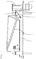
Fig. 1 Gesamtansicht Jack-Up-Barge mit an Monopilegründung angedockter MMU, -
Fig. 2 MMU liegend auf Deck der Jack-Up-Barge mit Aufrichtvorrichtung, -
Fig. 3 MMU-Ansicht von oben an Monopile und die Verbindung zur Jack-Up-Barge mit einem Gelenk und verschiebbarer Plattform, -
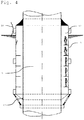
Fig. 4 Gesamtansicht der MMU in Schnittdarstellung an Monopile, -
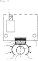
Fig. 5 die Darstellung des Andockkens der MMU im geöffneten Zustand der MMU bestehend aus zwei Halbschalen, -
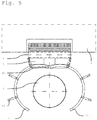
Fig. 6 Darstellung der angedockten MMU um Monopile, -
Fig. 7 aufgerichtete und geöffnete MMU auf Jack-Up-Barge, -
Fig. 8 eine geschlossene MMU in einer Ausführung mit einer Halbschale und zwei Viertelschalen an einer Jack-Up-Barge und Monopile und -
Fig. 9 eine geöffnete MMU in einer Ausführung mit einer Halbschale und zwei Viertelschalen an einer Jack-Up-Barge und Monopile. - Die selbstfahrende Jack-Up-Barge 1 ist vorteilhaft in einer Größenordnung von etwa 100 m Länge und ca. 65 m Breite ausgeführt und besitzt Beine in einer Länge von ca. 50 m. Auf der Jack-Up-Barge 1 befindet sich ein Kran 8, eine oder zwei MMU 3, ein hydraulisches Aufrichtsystem 2 für die MMU 3. Weiterhin eine ausreichende Ballastkapazität, um das Kontergewicht ausgleichen zu können, vorgesehen. Die hydraulische Aufrichtvorrichtung 2 ist am Heck der Jack-Up-Barge 1 vorgesehen. Sie besteht aus zwei Führungsschienen 5, auf der eine MMU 3 verfahrbar angeordnet ist. Beide Führungsschienen 5 sind an einem Gelenksystem 6 verfahrbar angeordnet. Das Gelenksystem 6 zwischen den Führungsschienen 5 und dem Heck angeordnet und horizontal verschiebbar mittels einer verschiebbaren Plattform 14 ausgeführt. Zwischen dem Heck und den oberen Enden der Führungsschienen 5 sind dazwischenliegende Hydrauliksysteme 7 zum Aufrichten der Führungsschienen 5 mit dem daran hängenden MMU 3, angeordnet. Somit lässt sich mit dem hydraulischen Aufrichtsystem 2 auch gleichzeitig eine unterschiedliche Lage der MMU 3 an den Führungsschienen 5 und damit für später eine gewünschte Höhe bzw. Tiefe am Monopile 9 einstellen.
- Die MMU 3 besteht aus zwei Halbschalen 3.1 oder bei einer Variante für größere Monopiledurchmesser aus einer Halbschale 3.1 und zwei Viertelschalen 3.2. Die zwei Halbschalen 3.1 bzw. die Halbschale 3.1 mit den Viertelschalen 3.2 sind jeweils mit einem Scharnier 13 miteinander verbunden. Die beiden Halbschalen 3.1 sind wiederum am Scharnier 13 bzw. die Halbschale 3.1 mit den beiden Viertelschalen 3.2 ist an ihrer Rückseite an dem Gelenksystem 6 bzw. an den Führungsschienen 5 angeordnet. Zwischen dem Gelenksystem 6 bzw. den Führungsschienen 5 und den Halbschalen 3.1 bzw. Viertelschalen 3.2 sind Hydraulikelemente 7 angeordnet. Diese dienen zum Öffnen bzw. Schließen der MMU 3. Bei der Ausführungsvariante mit einer Halbschale 3.1 und zwei Viertelschalen 3.2 ist es vorteilhaft, wenn die Hydraulikelemente an den Viertelschalen 3.2 an radial abstehende Winkelelemente angebracht sind. Damit verbessert sich das Hebelverhältnis der angreifenden Hydraulikelemente 7 und das Öffnen und Schließen kann mit einem geringeren Kraftaufwand realisiert werden.
- Nach dem Aufstellen und Verankerung der Jack-Up-Barge 1 am gewünschten Zielort kann das hydraulische Aufrichtsystem 2 die auf dem Heck auf den Führungsschienen 5 liegende MMU 3 senkrecht aufstellen. Die MMU 3 wird anschließend mittels Hydraulikelementen 7 geöffnet und gleichzeitig auf die gewünschte Höhe gefahren. Danach wird die MMU 3 an das Monopile 9 herangefahren und bei gleichzeitigem Ausfahren von hydraulischen Stützen 10 am oberen Rand der MMU 3 zwischen MMU 3 und Monopile 9 geschlossen. Hierbei umfasst die MMU 3 das Monopile 9 und bildet einen abgedichteten Arbeitsraum 12, begrenzt durch das Monopile 9 und die Außenwand der MMU 3. Dieser Arbeitsraum 12 wird anschließend leergepumt und somit entsteht ein Arbeitsraum 12 für Wartungsarbeiten am Monopile 9.
- An allen Berührungsflächen der MMU-Teile 3 untereinander und zur Monopile 9 sind Dichtungen vorgesehen. Zusätzlich können noch aufblasbare, schlauchartige Dichtungselemente an den Berührungsflächen der MMU 3 zur Monopile 0 angeordnet sein. Hierzu sind an der MMU entsprechende Aufnahmen für die Dichtungselemente vorgesehen. Diese aufblasbaren Dichtungselemente stellen also zusätzliche Dichtungen dar.
- 1
- - Jack-Up-Barge
- 2
- - hydraulisches Aufrichtsystem
- 3
- - Cofferdam-System, MMU, MMU-Teile
- 4
- - Verbindungselemente, Gangway, Versorgungsleitung, Entsorgungsleitung
- 5
- - Führungsschiene
- 6
- - Gelenksystem
- 7
- - Hydraulikelemente
- 8
- - Kran
- 9
- - Monopile
- 10
- - Wellenbrecher
- 11
- - hydraulische Stützen
- 12
- - Arbeitsraum
- 13
- - Scharnier
- 14
- - verfahrbare Plattform
- 15
- - Dichtungselement
Claims (7)
- Einrichtung zur Anbringung eines Cofferdam-Systems (3) an Monopile (9) von Offshorebauwerken zwecks Wartung der Monopile-Gründung (9),
dadurch gekennzeichnet,
dass die komplette Einrichtung aus einer selbstfahrenden Jack-Up-Barge (1), einem hydraulischen Aufrichtsystem (2) mit zwei Führungsschienen (5) und einem Gelenksystem (6) für das Aufrichten des Cofferdam-System (3), wobei die Führungsschienen (5) und das Gelenksystem (6) an einer verschiebbaren Plattform (14) angeordnet sind und das eigentliche Cofferdam-System (3) als Monopile Maintenance Unit (MMU) (3) und verschiedenste Verbindungselemente (4), wie z. B. eine Gangway (4), Versorgungsleitungen (4) und Entsorgungsleitungen (4) zwischen Jack-Up-Barge (1) und MMU (3) besteht. - Einrichtung nach Anspruch 1,
dadurch gekennzeichnet,
dass die MMU (3) aus zwei Halbschalen (3.1) oder einer Halbschale (3.1) und zwei Viertelschalen (3.2) besteht und die zwei Halbschalen (3.1) bzw. die Halbschale (3.1) mit den Viertelschalen (3.2) jeweils mit einem Scharnier (13) verbunden sind und die beiden Halbschalen (3.1) am Scharnier (13) bzw. die Halbschale (3.1) mit den beiden Viertelschalen (3.2) an ihrer Rückseite an dem Gelenksystem (6) bzw. den Führungsschienen (5) lösbar angeordnet ist und dass zwischen dem Gelenksystem (6) bzw. den Führungsschienen (5) und den Halbschalen (3.1) bzw. Viertelschalen (3.2) Hydraulikelemente (7) angeordnet sind. - Einrichtung nach einem der vorhergehenden Ansprüche,
dadurch gekennzeichnet,
dass die Jack-Up-Barge (1) als aufbockender Lastkahn mindestens eine Beinlänge von 50 m, eine Länge von 100 m und eine Breite von etwa 65 m bei einer ausreichenden Ballastkapazität entsprechend des MMU-Gewichts besitzt und auf dem Heck der Jack-Up-Barge (1) das hydraulische Aufrichtsystem (2), bestehend aus zwei Führungsschienen (5) für die darauf verfahrbare MMU (3) und beide Führungsschienen (5) selber an dem Gelenksystem (6) verfahrbar sind, das Gelenksystem (6) zwischen den Führungsschienen (5) und dem Heck angeordnet und horizontal verschiebbar ist und zwischen dem Heck und den oberen Enden der Führungsschienen (5) dazwischenliegende Hydraulikelemente (7) zum Aufrichten der Führungsschienen (5) mit dem daran hängenden MMU (3), angeordnet sind. - Einrichtung nach einem der vorhergehenden Ansprüche,
dadurch gekennzeichnet,
dass auf der Jack-Up-Barge (1) ein Kran (8) und mindestens zwei MMU (1) für unterschiedliche Durchmesser der Monopiles (9) vorgesehen sind. - Einrichtung nach einem der vorhergehenden Ansprüche,
dadurch gekennzeichnet,
dass das MMU (3) im oberen Bereich einen Wellenbrecher (10) besitzt und dieser vorteilhaft aus einem gelochten Blech besteht. - Einrichtung nach einem der vorhergehenden Ansprüche,
dadurch gekennzeichnet,
dass das MMU (3) an den Berührungsflächen zur Monopiles (9) aufblasbare, schlauchartige Dichtungselemente in dafür vorgesehene Aufnahmen besitzt. - Verfahren zur Anbringung eines Cofferdam-Systems (3) an Monopile (9) von Offshorebauwerken zwecks Wartung der Monopile-Gründung (9) unter Nutzung der Einrichtung nach Anspruch 1 bis 4,
dadurch gekennzeichnet,
dass nach dem Aufstellen und Verankerung der Jack-Up-Barge (1) am gewünschten Zielort das hydraulische Aufrichtsystem (2) die auf dem Heck liegende MMU (3) senkrecht aufstellt, die MMU (3) mittels Hydraulikelementen (7) anschließend geöffnet wird und gleichzeitig auf die gewünschte Höhe gefahren wird, danach die MMU (3) an das Monopile (9) herangefahren und bei gleichzeitigem Ausfahren von hydraulischen Stützen (11) zwischen MMU (3) und Monopile (9) mittels der Hydraulikelemente (7) geschlossen wird, wobei die MMU (3) das Monopile (9) umfasst und ein abgedichteter Arbeitsraum (12), begrenzt durch das Monopile (9) und die MMU (3), entsteht und dieser Arbeitsraum (12) anschließend leergepumt wird und somit ein Arbeitsraum (12) für Wartungsarbeiten an das Monopile (9) entsteht.
Priority Applications (1)
| Application Number | Priority Date | Filing Date | Title |
|---|---|---|---|
| PL17150733T PL3190233T3 (pl) | 2016-01-10 | 2017-01-09 | Urządzenie i przynależny sposób umieszczania koferdamu przy monopalu konstrukcji offshore w celu konserwacji fundamentu monopalowego |
Applications Claiming Priority (2)
| Application Number | Priority Date | Filing Date | Title |
|---|---|---|---|
| DE102016100283 | 2016-01-10 | ||
| DE102016125903 | 2016-12-29 |
Publications (2)
| Publication Number | Publication Date |
|---|---|
| EP3190233A1 true EP3190233A1 (de) | 2017-07-12 |
| EP3190233B1 EP3190233B1 (de) | 2019-03-13 |
Family
ID=57796166
Family Applications (1)
| Application Number | Title | Priority Date | Filing Date |
|---|---|---|---|
| EP17150733.8A Active EP3190233B1 (de) | 2016-01-10 | 2017-01-09 | Einrichtung und dazugehoeriges verfahren zur anbringung eines cofferdam-systems an monopile von offshorebauwerken zwecks wartung der monopile-gruendung |
Country Status (3)
| Country | Link |
|---|---|
| EP (1) | EP3190233B1 (de) |
| DK (1) | DK3190233T3 (de) |
| PL (1) | PL3190233T3 (de) |
Citations (7)
| Publication number | Priority date | Publication date | Assignee | Title |
|---|---|---|---|---|
| JP2006249685A (ja) * | 2005-03-08 | 2006-09-21 | Jfe Engineering Kk | 水中構造物の仮締切工法及び仮締切用構造体 |
| EP2020463A1 (de) * | 2007-08-02 | 2009-02-04 | WeserWind GmbH | Kofferdamm und Verfahren zur Abstimmung eines Offshore-Aufbaus gegen umgebendes Wasser unter Verwendung desselben |
| DE102008029982A1 (de) | 2008-06-24 | 2009-12-31 | Schopf, Walter, Dipl.-Ing. | Stabilisierungs- und Wartungseinrichtung für seilabgespannte am Meeresboden aufsitzende, sowie für verankerte schwimmende Trägereinrichtungen an Offshore-Energieanlagen |
| DE102010030694A1 (de) | 2010-06-30 | 2012-01-05 | Maschinenbau Und Umwelttechnik Gmbh (Mbu) | Vorrichtung und Verfahren zur Durchführung von Arbeiten an Offshore-Bauwerken |
| TW201215538A (en) * | 2010-10-01 | 2012-04-16 | Daiichi Kensetsu Kiko Co Ltd | Deck elevating type operating platform vessel and construction method of offshore wind power generation facilities |
| DE102012023195A1 (de) * | 2012-11-28 | 2014-05-28 | Michael Detering | Arbeits-Ringkammer |
| NL2011779C2 (nl) | 2013-11-11 | 2015-05-13 | Boskalis Offshore Subsea Services Europ B V | Werkwijze voor het behandelen van een paal, alsmede werkwijze daarvoor. |
-
2017
- 2017-01-09 DK DK17150733.8T patent/DK3190233T3/da active
- 2017-01-09 EP EP17150733.8A patent/EP3190233B1/de active Active
- 2017-01-09 PL PL17150733T patent/PL3190233T3/pl unknown
Patent Citations (7)
| Publication number | Priority date | Publication date | Assignee | Title |
|---|---|---|---|---|
| JP2006249685A (ja) * | 2005-03-08 | 2006-09-21 | Jfe Engineering Kk | 水中構造物の仮締切工法及び仮締切用構造体 |
| EP2020463A1 (de) * | 2007-08-02 | 2009-02-04 | WeserWind GmbH | Kofferdamm und Verfahren zur Abstimmung eines Offshore-Aufbaus gegen umgebendes Wasser unter Verwendung desselben |
| DE102008029982A1 (de) | 2008-06-24 | 2009-12-31 | Schopf, Walter, Dipl.-Ing. | Stabilisierungs- und Wartungseinrichtung für seilabgespannte am Meeresboden aufsitzende, sowie für verankerte schwimmende Trägereinrichtungen an Offshore-Energieanlagen |
| DE102010030694A1 (de) | 2010-06-30 | 2012-01-05 | Maschinenbau Und Umwelttechnik Gmbh (Mbu) | Vorrichtung und Verfahren zur Durchführung von Arbeiten an Offshore-Bauwerken |
| TW201215538A (en) * | 2010-10-01 | 2012-04-16 | Daiichi Kensetsu Kiko Co Ltd | Deck elevating type operating platform vessel and construction method of offshore wind power generation facilities |
| DE102012023195A1 (de) * | 2012-11-28 | 2014-05-28 | Michael Detering | Arbeits-Ringkammer |
| NL2011779C2 (nl) | 2013-11-11 | 2015-05-13 | Boskalis Offshore Subsea Services Europ B V | Werkwijze voor het behandelen van een paal, alsmede werkwijze daarvoor. |
Also Published As
| Publication number | Publication date |
|---|---|
| DK3190233T3 (da) | 2019-06-17 |
| EP3190233B1 (de) | 2019-03-13 |
| PL3190233T3 (pl) | 2019-09-30 |
Similar Documents
| Publication | Publication Date | Title |
|---|---|---|
| DE10349109B4 (de) | Gründung für eine Offshore-Windenergieanlage | |
| EP1288122B1 (de) | Schwimmfundament für ein über die Wasseroberfläche aufragendes Bauwerk | |
| DE2459478C3 (de) | Verfahren zur Errichtung einer künstlichen Insel | |
| DE10034847A1 (de) | Ortsfeste Positionierung von Funktionseinheiten auf dem oder im Wasser | |
| DE2838281A1 (de) | Meeresbodenschablone | |
| DE2416357A1 (de) | Verfahren und vorrichtung zum umwandeln eines schwimmponton in ein halb-tauchfaehiges schwimmfahrzeug, insbesondere eine schwimmende arbeitsinsel | |
| DE102018115358A1 (de) | Schwimmtragwerk für eine Windkraftanlage | |
| DE102010020995B4 (de) | Gründungssystem für die Gründung einer Offshore-Windenergieanlage | |
| EP2623674A1 (de) | Unterkonstruktion für eine Offshore-Plattform und Verfahren zum Installieren einer derartigen Unterkonstruktion | |
| DE1255609B (de) | Vorrichtung zum Anschliessen eines Bohrlochkopfes einer Unterwasserbohrung | |
| WO2016177783A1 (de) | Schwimmfähiger schwergewichtsanker zur verankerung eines in der offenen see schwimmenden tragwerks mit einer windkraftanlage, servicestation oder konverterstation | |
| EP3190233B1 (de) | Einrichtung und dazugehoeriges verfahren zur anbringung eines cofferdam-systems an monopile von offshorebauwerken zwecks wartung der monopile-gruendung | |
| DE102016011572A1 (de) | Bauwerk zur Errichtung an Gewässeroberflächen und Verfahren zu seiner Errichtung | |
| WO2010115933A2 (de) | Verfahren zum errichten einer off-shore-anlage und off-shore-anlage | |
| EP2020463A1 (de) | Kofferdamm und Verfahren zur Abstimmung eines Offshore-Aufbaus gegen umgebendes Wasser unter Verwendung desselben | |
| DE202010010094U1 (de) | Gründungssystem für die Gründung einer Offshore-Windenergieanlage | |
| EP1634998A1 (de) | Transport und Gründung von Funktionseinheiten, insbesondere Offshore-Windkraftanlagen | |
| EP3530814B1 (de) | Verfahren zur gründung einer umspannplattform und gründungsset für umspannfplattform | |
| EP1565619B1 (de) | Vorrichtung zum anlegen eines wasserfahrzeuges an einem wasserbauwerk | |
| AT523731B1 (de) | Motorik- und erlebnispark | |
| EP3255211B1 (de) | Jackup-brückenstruktur | |
| DE102017117552B4 (de) | Wasserfahrzeug und Druckluftverteileinrichtung | |
| EP2860314B1 (de) | Schwerkraftgründung | |
| EP1384883A1 (de) | Transporteinrichtung für Offshore-Windturbinen | |
| DE102011120378A1 (de) | Offshore-Windkraftanlage und Verfahren zum Aufbau und zur Aufstellung der Offshore-Windkraftanlage |
Legal Events
| Date | Code | Title | Description |
|---|---|---|---|
| PUAI | Public reference made under article 153(3) epc to a published international application that has entered the european phase |
Free format text: ORIGINAL CODE: 0009012 |
|
| STAA | Information on the status of an ep patent application or granted ep patent |
Free format text: STATUS: THE APPLICATION HAS BEEN PUBLISHED |
|
| AK | Designated contracting states |
Kind code of ref document: A1 Designated state(s): AL AT BE BG CH CY CZ DE DK EE ES FI FR GB GR HR HU IE IS IT LI LT LU LV MC MK MT NL NO PL PT RO RS SE SI SK SM TR |
|
| AX | Request for extension of the european patent |
Extension state: BA ME |
|
| STAA | Information on the status of an ep patent application or granted ep patent |
Free format text: STATUS: REQUEST FOR EXAMINATION WAS MADE |
|
| 17P | Request for examination filed |
Effective date: 20180112 |
|
| RBV | Designated contracting states (corrected) |
Designated state(s): AL AT BE BG CH CY CZ DE DK EE ES FI FR GB GR HR HU IE IS IT LI LT LU LV MC MK MT NL NO PL PT RO RS SE SI SK SM TR |
|
| GRAP | Despatch of communication of intention to grant a patent |
Free format text: ORIGINAL CODE: EPIDOSNIGR1 |
|
| STAA | Information on the status of an ep patent application or granted ep patent |
Free format text: STATUS: GRANT OF PATENT IS INTENDED |
|
| INTG | Intention to grant announced |
Effective date: 20180803 |
|
| GRAS | Grant fee paid |
Free format text: ORIGINAL CODE: EPIDOSNIGR3 |
|
| GRAA | (expected) grant |
Free format text: ORIGINAL CODE: 0009210 |
|
| STAA | Information on the status of an ep patent application or granted ep patent |
Free format text: STATUS: THE PATENT HAS BEEN GRANTED |
|
| AK | Designated contracting states |
Kind code of ref document: B1 Designated state(s): AL AT BE BG CH CY CZ DE DK EE ES FI FR GB GR HR HU IE IS IT LI LT LU LV MC MK MT NL NO PL PT RO RS SE SI SK SM TR |
|
| REG | Reference to a national code |
Ref country code: GB Ref legal event code: FG4D Free format text: NOT ENGLISH |
|
| REG | Reference to a national code |
Ref country code: AT Ref legal event code: REF Ref document number: 1107830 Country of ref document: AT Kind code of ref document: T Effective date: 20190315 Ref country code: CH Ref legal event code: EP |
|
| REG | Reference to a national code |
Ref country code: DE Ref legal event code: R096 Ref document number: 502017000902 Country of ref document: DE |
|
| REG | Reference to a national code |
Ref country code: IE Ref legal event code: FG4D Free format text: LANGUAGE OF EP DOCUMENT: GERMAN |
|
| RAP2 | Party data changed (patent owner data changed or rights of a patent transferred) |
Owner name: ABC ALBA BUSINESS CONSULTANCY E.K |
|
| REG | Reference to a national code |
Ref country code: DK Ref legal event code: T3 Effective date: 20190613 |
|
| REG | Reference to a national code |
Ref country code: NL Ref legal event code: FP |
|
| REG | Reference to a national code |
Ref country code: NO Ref legal event code: T2 Effective date: 20190313 |
|
| REG | Reference to a national code |
Ref country code: LT Ref legal event code: MG4D |
|
| PG25 | Lapsed in a contracting state [announced via postgrant information from national office to epo] |
Ref country code: SE Free format text: LAPSE BECAUSE OF FAILURE TO SUBMIT A TRANSLATION OF THE DESCRIPTION OR TO PAY THE FEE WITHIN THE PRESCRIBED TIME-LIMIT Effective date: 20190313 Ref country code: FI Free format text: LAPSE BECAUSE OF FAILURE TO SUBMIT A TRANSLATION OF THE DESCRIPTION OR TO PAY THE FEE WITHIN THE PRESCRIBED TIME-LIMIT Effective date: 20190313 Ref country code: LT Free format text: LAPSE BECAUSE OF FAILURE TO SUBMIT A TRANSLATION OF THE DESCRIPTION OR TO PAY THE FEE WITHIN THE PRESCRIBED TIME-LIMIT Effective date: 20190313 |
|
| PG25 | Lapsed in a contracting state [announced via postgrant information from national office to epo] |
Ref country code: BG Free format text: LAPSE BECAUSE OF FAILURE TO SUBMIT A TRANSLATION OF THE DESCRIPTION OR TO PAY THE FEE WITHIN THE PRESCRIBED TIME-LIMIT Effective date: 20190613 Ref country code: HR Free format text: LAPSE BECAUSE OF FAILURE TO SUBMIT A TRANSLATION OF THE DESCRIPTION OR TO PAY THE FEE WITHIN THE PRESCRIBED TIME-LIMIT Effective date: 20190313 Ref country code: GR Free format text: LAPSE BECAUSE OF FAILURE TO SUBMIT A TRANSLATION OF THE DESCRIPTION OR TO PAY THE FEE WITHIN THE PRESCRIBED TIME-LIMIT Effective date: 20190614 Ref country code: LV Free format text: LAPSE BECAUSE OF FAILURE TO SUBMIT A TRANSLATION OF THE DESCRIPTION OR TO PAY THE FEE WITHIN THE PRESCRIBED TIME-LIMIT Effective date: 20190313 Ref country code: RS Free format text: LAPSE BECAUSE OF FAILURE TO SUBMIT A TRANSLATION OF THE DESCRIPTION OR TO PAY THE FEE WITHIN THE PRESCRIBED TIME-LIMIT Effective date: 20190313 |
|
| PG25 | Lapsed in a contracting state [announced via postgrant information from national office to epo] |
Ref country code: IT Free format text: LAPSE BECAUSE OF FAILURE TO SUBMIT A TRANSLATION OF THE DESCRIPTION OR TO PAY THE FEE WITHIN THE PRESCRIBED TIME-LIMIT Effective date: 20190313 Ref country code: PT Free format text: LAPSE BECAUSE OF FAILURE TO SUBMIT A TRANSLATION OF THE DESCRIPTION OR TO PAY THE FEE WITHIN THE PRESCRIBED TIME-LIMIT Effective date: 20190713 Ref country code: AL Free format text: LAPSE BECAUSE OF FAILURE TO SUBMIT A TRANSLATION OF THE DESCRIPTION OR TO PAY THE FEE WITHIN THE PRESCRIBED TIME-LIMIT Effective date: 20190313 Ref country code: ES Free format text: LAPSE BECAUSE OF FAILURE TO SUBMIT A TRANSLATION OF THE DESCRIPTION OR TO PAY THE FEE WITHIN THE PRESCRIBED TIME-LIMIT Effective date: 20190313 Ref country code: RO Free format text: LAPSE BECAUSE OF FAILURE TO SUBMIT A TRANSLATION OF THE DESCRIPTION OR TO PAY THE FEE WITHIN THE PRESCRIBED TIME-LIMIT Effective date: 20190313 Ref country code: CZ Free format text: LAPSE BECAUSE OF FAILURE TO SUBMIT A TRANSLATION OF THE DESCRIPTION OR TO PAY THE FEE WITHIN THE PRESCRIBED TIME-LIMIT Effective date: 20190313 Ref country code: EE Free format text: LAPSE BECAUSE OF FAILURE TO SUBMIT A TRANSLATION OF THE DESCRIPTION OR TO PAY THE FEE WITHIN THE PRESCRIBED TIME-LIMIT Effective date: 20190313 Ref country code: SK Free format text: LAPSE BECAUSE OF FAILURE TO SUBMIT A TRANSLATION OF THE DESCRIPTION OR TO PAY THE FEE WITHIN THE PRESCRIBED TIME-LIMIT Effective date: 20190313 |
|
| PG25 | Lapsed in a contracting state [announced via postgrant information from national office to epo] |
Ref country code: SM Free format text: LAPSE BECAUSE OF FAILURE TO SUBMIT A TRANSLATION OF THE DESCRIPTION OR TO PAY THE FEE WITHIN THE PRESCRIBED TIME-LIMIT Effective date: 20190313 |
|
| REG | Reference to a national code |
Ref country code: DE Ref legal event code: R097 Ref document number: 502017000902 Country of ref document: DE |
|
| PG25 | Lapsed in a contracting state [announced via postgrant information from national office to epo] |
Ref country code: IS Free format text: LAPSE BECAUSE OF FAILURE TO SUBMIT A TRANSLATION OF THE DESCRIPTION OR TO PAY THE FEE WITHIN THE PRESCRIBED TIME-LIMIT Effective date: 20190713 |
|
| PLBE | No opposition filed within time limit |
Free format text: ORIGINAL CODE: 0009261 |
|
| STAA | Information on the status of an ep patent application or granted ep patent |
Free format text: STATUS: NO OPPOSITION FILED WITHIN TIME LIMIT |
|
| 26N | No opposition filed |
Effective date: 20191216 |
|
| PG25 | Lapsed in a contracting state [announced via postgrant information from national office to epo] |
Ref country code: SI Free format text: LAPSE BECAUSE OF FAILURE TO SUBMIT A TRANSLATION OF THE DESCRIPTION OR TO PAY THE FEE WITHIN THE PRESCRIBED TIME-LIMIT Effective date: 20190313 |
|
| PG25 | Lapsed in a contracting state [announced via postgrant information from national office to epo] |
Ref country code: TR Free format text: LAPSE BECAUSE OF FAILURE TO SUBMIT A TRANSLATION OF THE DESCRIPTION OR TO PAY THE FEE WITHIN THE PRESCRIBED TIME-LIMIT Effective date: 20190313 |
|
| PG25 | Lapsed in a contracting state [announced via postgrant information from national office to epo] |
Ref country code: MC Free format text: LAPSE BECAUSE OF FAILURE TO SUBMIT A TRANSLATION OF THE DESCRIPTION OR TO PAY THE FEE WITHIN THE PRESCRIBED TIME-LIMIT Effective date: 20190313 |
|
| REG | Reference to a national code |
Ref country code: CH Ref legal event code: PL |
|
| PG25 | Lapsed in a contracting state [announced via postgrant information from national office to epo] |
Ref country code: LU Free format text: LAPSE BECAUSE OF NON-PAYMENT OF DUE FEES Effective date: 20200109 |
|
| PG25 | Lapsed in a contracting state [announced via postgrant information from national office to epo] |
Ref country code: LI Free format text: LAPSE BECAUSE OF NON-PAYMENT OF DUE FEES Effective date: 20200131 Ref country code: CH Free format text: LAPSE BECAUSE OF NON-PAYMENT OF DUE FEES Effective date: 20200131 |
|
| PG25 | Lapsed in a contracting state [announced via postgrant information from national office to epo] |
Ref country code: IE Free format text: LAPSE BECAUSE OF NON-PAYMENT OF DUE FEES Effective date: 20200109 |
|
| PG25 | Lapsed in a contracting state [announced via postgrant information from national office to epo] |
Ref country code: MT Free format text: LAPSE BECAUSE OF FAILURE TO SUBMIT A TRANSLATION OF THE DESCRIPTION OR TO PAY THE FEE WITHIN THE PRESCRIBED TIME-LIMIT Effective date: 20190313 Ref country code: CY Free format text: LAPSE BECAUSE OF FAILURE TO SUBMIT A TRANSLATION OF THE DESCRIPTION OR TO PAY THE FEE WITHIN THE PRESCRIBED TIME-LIMIT Effective date: 20190313 |
|
| PG25 | Lapsed in a contracting state [announced via postgrant information from national office to epo] |
Ref country code: MK Free format text: LAPSE BECAUSE OF FAILURE TO SUBMIT A TRANSLATION OF THE DESCRIPTION OR TO PAY THE FEE WITHIN THE PRESCRIBED TIME-LIMIT Effective date: 20190313 |
|
| PG25 | Lapsed in a contracting state [announced via postgrant information from national office to epo] |
Ref country code: PL Free format text: LAPSE BECAUSE OF NON-PAYMENT OF DUE FEES Effective date: 20200109 |
|
| REG | Reference to a national code |
Ref country code: AT Ref legal event code: MM01 Ref document number: 1107830 Country of ref document: AT Kind code of ref document: T Effective date: 20220109 |
|
| PG25 | Lapsed in a contracting state [announced via postgrant information from national office to epo] |
Ref country code: AT Free format text: LAPSE BECAUSE OF NON-PAYMENT OF DUE FEES Effective date: 20220109 |
|
| P01 | Opt-out of the competence of the unified patent court (upc) registered |
Effective date: 20230524 |
|
| PGFP | Annual fee paid to national office [announced via postgrant information from national office to epo] |
Ref country code: NL Payment date: 20230731 Year of fee payment: 7 |
|
| PGFP | Annual fee paid to national office [announced via postgrant information from national office to epo] |
Ref country code: NO Payment date: 20230801 Year of fee payment: 7 Ref country code: GB Payment date: 20230731 Year of fee payment: 7 |
|
| PGFP | Annual fee paid to national office [announced via postgrant information from national office to epo] |
Ref country code: FR Payment date: 20230728 Year of fee payment: 7 Ref country code: DK Payment date: 20230731 Year of fee payment: 7 Ref country code: DE Payment date: 20230728 Year of fee payment: 7 Ref country code: BE Payment date: 20230731 Year of fee payment: 7 |
|
| PGFP | Annual fee paid to national office [announced via postgrant information from national office to epo] |
Ref country code: NL Payment date: 20240122 Year of fee payment: 8 |