EP3188697B1 - Systèmes pour commande de suspension de vide intelligente - Google Patents
Systèmes pour commande de suspension de vide intelligente Download PDFInfo
- Publication number
- EP3188697B1 EP3188697B1 EP15838325.7A EP15838325A EP3188697B1 EP 3188697 B1 EP3188697 B1 EP 3188697B1 EP 15838325 A EP15838325 A EP 15838325A EP 3188697 B1 EP3188697 B1 EP 3188697B1
- Authority
- EP
- European Patent Office
- Prior art keywords
- socket
- motion
- pressure
- vacuum
- prosthetic
- Prior art date
- Legal status (The legal status is an assumption and is not a legal conclusion. Google has not performed a legal analysis and makes no representation as to the accuracy of the status listed.)
- Active
Links
- 239000000725 suspension Substances 0.000 title claims description 171
- 230000033001 locomotion Effects 0.000 claims description 224
- 230000000694 effects Effects 0.000 claims description 114
- 230000005021 gait Effects 0.000 claims description 54
- 238000004891 communication Methods 0.000 claims description 33
- 230000001052 transient effect Effects 0.000 claims description 11
- 230000002411 adverse Effects 0.000 claims description 9
- 210000003414 extremity Anatomy 0.000 description 119
- 238000000034 method Methods 0.000 description 84
- 230000003044 adaptive effect Effects 0.000 description 22
- QQWUGDVOUVUTOY-UHFFFAOYSA-N 5-chloro-N2-[2-methoxy-4-[4-(4-methyl-1-piperazinyl)-1-piperidinyl]phenyl]-N4-(2-propan-2-ylsulfonylphenyl)pyrimidine-2,4-diamine Chemical compound COC1=CC(N2CCC(CC2)N2CCN(C)CC2)=CC=C1NC(N=1)=NC=C(Cl)C=1NC1=CC=CC=C1S(=O)(=O)C(C)C QQWUGDVOUVUTOY-UHFFFAOYSA-N 0.000 description 20
- 230000001133 acceleration Effects 0.000 description 13
- 238000012544 monitoring process Methods 0.000 description 13
- 238000011156 evaluation Methods 0.000 description 10
- 230000004044 response Effects 0.000 description 9
- 230000002596 correlated effect Effects 0.000 description 8
- 230000003190 augmentative effect Effects 0.000 description 7
- 230000006870 function Effects 0.000 description 7
- 230000008859 change Effects 0.000 description 6
- 210000003127 knee Anatomy 0.000 description 6
- 230000008569 process Effects 0.000 description 6
- 238000012545 processing Methods 0.000 description 6
- 230000000875 corresponding effect Effects 0.000 description 5
- 230000001965 increasing effect Effects 0.000 description 5
- 230000001939 inductive effect Effects 0.000 description 5
- 238000005070 sampling Methods 0.000 description 5
- 238000012360 testing method Methods 0.000 description 5
- 208000027418 Wounds and injury Diseases 0.000 description 4
- 230000008901 benefit Effects 0.000 description 4
- 230000006378 damage Effects 0.000 description 4
- 208000014674 injury Diseases 0.000 description 4
- 210000002414 leg Anatomy 0.000 description 4
- 230000002123 temporal effect Effects 0.000 description 4
- 230000007704 transition Effects 0.000 description 4
- 238000001514 detection method Methods 0.000 description 3
- 238000006073 displacement reaction Methods 0.000 description 3
- 210000002683 foot Anatomy 0.000 description 3
- 238000004364 calculation method Methods 0.000 description 2
- 238000012512 characterization method Methods 0.000 description 2
- 230000003247 decreasing effect Effects 0.000 description 2
- 230000001419 dependent effect Effects 0.000 description 2
- 230000036541 health Effects 0.000 description 2
- 230000003993 interaction Effects 0.000 description 2
- 230000001788 irregular Effects 0.000 description 2
- 210000003141 lower extremity Anatomy 0.000 description 2
- 238000012986 modification Methods 0.000 description 2
- 230000004048 modification Effects 0.000 description 2
- 238000010606 normalization Methods 0.000 description 2
- 230000003287 optical effect Effects 0.000 description 2
- 230000000284 resting effect Effects 0.000 description 2
- 239000007787 solid Substances 0.000 description 2
- 238000012546 transfer Methods 0.000 description 2
- 230000000007 visual effect Effects 0.000 description 2
- 208000032131 Diabetic Neuropathies Diseases 0.000 description 1
- 241000124033 Salix Species 0.000 description 1
- 230000004913 activation Effects 0.000 description 1
- 238000001994 activation Methods 0.000 description 1
- 230000009692 acute damage Effects 0.000 description 1
- 230000001154 acute effect Effects 0.000 description 1
- 230000004075 alteration Effects 0.000 description 1
- 238000004458 analytical method Methods 0.000 description 1
- 210000003423 ankle Anatomy 0.000 description 1
- 239000003990 capacitor Substances 0.000 description 1
- 230000010267 cellular communication Effects 0.000 description 1
- 239000003086 colorant Substances 0.000 description 1
- 238000007405 data analysis Methods 0.000 description 1
- 238000013461 design Methods 0.000 description 1
- 238000011161 development Methods 0.000 description 1
- 238000010586 diagram Methods 0.000 description 1
- 238000005516 engineering process Methods 0.000 description 1
- 230000001747 exhibiting effect Effects 0.000 description 1
- 230000037406 food intake Effects 0.000 description 1
- 235000012631 food intake Nutrition 0.000 description 1
- 230000005484 gravity Effects 0.000 description 1
- 230000006872 improvement Effects 0.000 description 1
- 238000010921 in-depth analysis Methods 0.000 description 1
- 230000006698 induction Effects 0.000 description 1
- 230000009191 jumping Effects 0.000 description 1
- 238000011542 limb amputation Methods 0.000 description 1
- 239000000463 material Substances 0.000 description 1
- 238000005259 measurement Methods 0.000 description 1
- 230000000272 proprioceptive effect Effects 0.000 description 1
- 230000009023 proprioceptive sensation Effects 0.000 description 1
- 230000009467 reduction Effects 0.000 description 1
- 230000035807 sensation Effects 0.000 description 1
- 238000000926 separation method Methods 0.000 description 1
- 238000007493 shaping process Methods 0.000 description 1
- 230000005236 sound signal Effects 0.000 description 1
- 230000009192 sprinting Effects 0.000 description 1
- 238000001356 surgical procedure Methods 0.000 description 1
- 208000019553 vascular disease Diseases 0.000 description 1
- 239000002023 wood Substances 0.000 description 1
Images


Classifications
-
- A—HUMAN NECESSITIES
- A61—MEDICAL OR VETERINARY SCIENCE; HYGIENE
- A61F—FILTERS IMPLANTABLE INTO BLOOD VESSELS; PROSTHESES; DEVICES PROVIDING PATENCY TO, OR PREVENTING COLLAPSING OF, TUBULAR STRUCTURES OF THE BODY, e.g. STENTS; ORTHOPAEDIC, NURSING OR CONTRACEPTIVE DEVICES; FOMENTATION; TREATMENT OR PROTECTION OF EYES OR EARS; BANDAGES, DRESSINGS OR ABSORBENT PADS; FIRST-AID KITS
- A61F2/00—Filters implantable into blood vessels; Prostheses, i.e. artificial substitutes or replacements for parts of the body; Appliances for connecting them with the body; Devices providing patency to, or preventing collapsing of, tubular structures of the body, e.g. stents
- A61F2/50—Prostheses not implantable in the body
- A61F2/68—Operating or control means
- A61F2/70—Operating or control means electrical
-
- A—HUMAN NECESSITIES
- A61—MEDICAL OR VETERINARY SCIENCE; HYGIENE
- A61F—FILTERS IMPLANTABLE INTO BLOOD VESSELS; PROSTHESES; DEVICES PROVIDING PATENCY TO, OR PREVENTING COLLAPSING OF, TUBULAR STRUCTURES OF THE BODY, e.g. STENTS; ORTHOPAEDIC, NURSING OR CONTRACEPTIVE DEVICES; FOMENTATION; TREATMENT OR PROTECTION OF EYES OR EARS; BANDAGES, DRESSINGS OR ABSORBENT PADS; FIRST-AID KITS
- A61F2/00—Filters implantable into blood vessels; Prostheses, i.e. artificial substitutes or replacements for parts of the body; Appliances for connecting them with the body; Devices providing patency to, or preventing collapsing of, tubular structures of the body, e.g. stents
- A61F2/50—Prostheses not implantable in the body
- A61F2/78—Means for protecting prostheses or for attaching them to the body, e.g. bandages, harnesses, straps, or stockings for the limb stump
- A61F2/80—Sockets, e.g. of suction type
-
- A—HUMAN NECESSITIES
- A61—MEDICAL OR VETERINARY SCIENCE; HYGIENE
- A61B—DIAGNOSIS; SURGERY; IDENTIFICATION
- A61B5/00—Measuring for diagnostic purposes; Identification of persons
- A61B5/48—Other medical applications
- A61B5/4851—Prosthesis assessment or monitoring
-
- A—HUMAN NECESSITIES
- A61—MEDICAL OR VETERINARY SCIENCE; HYGIENE
- A61F—FILTERS IMPLANTABLE INTO BLOOD VESSELS; PROSTHESES; DEVICES PROVIDING PATENCY TO, OR PREVENTING COLLAPSING OF, TUBULAR STRUCTURES OF THE BODY, e.g. STENTS; ORTHOPAEDIC, NURSING OR CONTRACEPTIVE DEVICES; FOMENTATION; TREATMENT OR PROTECTION OF EYES OR EARS; BANDAGES, DRESSINGS OR ABSORBENT PADS; FIRST-AID KITS
- A61F2/00—Filters implantable into blood vessels; Prostheses, i.e. artificial substitutes or replacements for parts of the body; Appliances for connecting them with the body; Devices providing patency to, or preventing collapsing of, tubular structures of the body, e.g. stents
- A61F2/50—Prostheses not implantable in the body
- A61F2/68—Operating or control means
- A61F2/74—Operating or control means fluid, i.e. hydraulic or pneumatic
- A61F2/741—Operating or control means fluid, i.e. hydraulic or pneumatic using powered actuators, e.g. stepper motors or solenoids
-
- A—HUMAN NECESSITIES
- A61—MEDICAL OR VETERINARY SCIENCE; HYGIENE
- A61F—FILTERS IMPLANTABLE INTO BLOOD VESSELS; PROSTHESES; DEVICES PROVIDING PATENCY TO, OR PREVENTING COLLAPSING OF, TUBULAR STRUCTURES OF THE BODY, e.g. STENTS; ORTHOPAEDIC, NURSING OR CONTRACEPTIVE DEVICES; FOMENTATION; TREATMENT OR PROTECTION OF EYES OR EARS; BANDAGES, DRESSINGS OR ABSORBENT PADS; FIRST-AID KITS
- A61F2/00—Filters implantable into blood vessels; Prostheses, i.e. artificial substitutes or replacements for parts of the body; Appliances for connecting them with the body; Devices providing patency to, or preventing collapsing of, tubular structures of the body, e.g. stents
- A61F2/50—Prostheses not implantable in the body
- A61F2/68—Operating or control means
- A61F2/74—Operating or control means fluid, i.e. hydraulic or pneumatic
- A61F2/742—Low pressure systems, e.g. vacuum pump
-
- A—HUMAN NECESSITIES
- A61—MEDICAL OR VETERINARY SCIENCE; HYGIENE
- A61B—DIAGNOSIS; SURGERY; IDENTIFICATION
- A61B5/00—Measuring for diagnostic purposes; Identification of persons
- A61B5/103—Detecting, measuring or recording devices for testing the shape, pattern, colour, size or movement of the body or parts thereof, for diagnostic purposes
- A61B5/11—Measuring movement of the entire body or parts thereof, e.g. head or hand tremor, mobility of a limb
- A61B5/1118—Determining activity level
-
- A—HUMAN NECESSITIES
- A61—MEDICAL OR VETERINARY SCIENCE; HYGIENE
- A61B—DIAGNOSIS; SURGERY; IDENTIFICATION
- A61B5/00—Measuring for diagnostic purposes; Identification of persons
- A61B5/103—Detecting, measuring or recording devices for testing the shape, pattern, colour, size or movement of the body or parts thereof, for diagnostic purposes
- A61B5/11—Measuring movement of the entire body or parts thereof, e.g. head or hand tremor, mobility of a limb
- A61B5/112—Gait analysis
-
- A—HUMAN NECESSITIES
- A61—MEDICAL OR VETERINARY SCIENCE; HYGIENE
- A61F—FILTERS IMPLANTABLE INTO BLOOD VESSELS; PROSTHESES; DEVICES PROVIDING PATENCY TO, OR PREVENTING COLLAPSING OF, TUBULAR STRUCTURES OF THE BODY, e.g. STENTS; ORTHOPAEDIC, NURSING OR CONTRACEPTIVE DEVICES; FOMENTATION; TREATMENT OR PROTECTION OF EYES OR EARS; BANDAGES, DRESSINGS OR ABSORBENT PADS; FIRST-AID KITS
- A61F2/00—Filters implantable into blood vessels; Prostheses, i.e. artificial substitutes or replacements for parts of the body; Appliances for connecting them with the body; Devices providing patency to, or preventing collapsing of, tubular structures of the body, e.g. stents
- A61F2/50—Prostheses not implantable in the body
- A61F2002/5016—Prostheses not implantable in the body adjustable
- A61F2002/5032—Prostheses not implantable in the body adjustable for adjusting fluid pressure
-
- A—HUMAN NECESSITIES
- A61—MEDICAL OR VETERINARY SCIENCE; HYGIENE
- A61F—FILTERS IMPLANTABLE INTO BLOOD VESSELS; PROSTHESES; DEVICES PROVIDING PATENCY TO, OR PREVENTING COLLAPSING OF, TUBULAR STRUCTURES OF THE BODY, e.g. STENTS; ORTHOPAEDIC, NURSING OR CONTRACEPTIVE DEVICES; FOMENTATION; TREATMENT OR PROTECTION OF EYES OR EARS; BANDAGES, DRESSINGS OR ABSORBENT PADS; FIRST-AID KITS
- A61F2/00—Filters implantable into blood vessels; Prostheses, i.e. artificial substitutes or replacements for parts of the body; Appliances for connecting them with the body; Devices providing patency to, or preventing collapsing of, tubular structures of the body, e.g. stents
- A61F2/50—Prostheses not implantable in the body
- A61F2002/5016—Prostheses not implantable in the body adjustable
- A61F2002/5036—Prostheses not implantable in the body adjustable self-adjustable, e.g. self-learning
-
- A—HUMAN NECESSITIES
- A61—MEDICAL OR VETERINARY SCIENCE; HYGIENE
- A61F—FILTERS IMPLANTABLE INTO BLOOD VESSELS; PROSTHESES; DEVICES PROVIDING PATENCY TO, OR PREVENTING COLLAPSING OF, TUBULAR STRUCTURES OF THE BODY, e.g. STENTS; ORTHOPAEDIC, NURSING OR CONTRACEPTIVE DEVICES; FOMENTATION; TREATMENT OR PROTECTION OF EYES OR EARS; BANDAGES, DRESSINGS OR ABSORBENT PADS; FIRST-AID KITS
- A61F2/00—Filters implantable into blood vessels; Prostheses, i.e. artificial substitutes or replacements for parts of the body; Appliances for connecting them with the body; Devices providing patency to, or preventing collapsing of, tubular structures of the body, e.g. stents
- A61F2/50—Prostheses not implantable in the body
- A61F2/68—Operating or control means
- A61F2/70—Operating or control means electrical
- A61F2002/704—Operating or control means electrical computer-controlled, e.g. robotic control
-
- A—HUMAN NECESSITIES
- A61—MEDICAL OR VETERINARY SCIENCE; HYGIENE
- A61F—FILTERS IMPLANTABLE INTO BLOOD VESSELS; PROSTHESES; DEVICES PROVIDING PATENCY TO, OR PREVENTING COLLAPSING OF, TUBULAR STRUCTURES OF THE BODY, e.g. STENTS; ORTHOPAEDIC, NURSING OR CONTRACEPTIVE DEVICES; FOMENTATION; TREATMENT OR PROTECTION OF EYES OR EARS; BANDAGES, DRESSINGS OR ABSORBENT PADS; FIRST-AID KITS
- A61F2/00—Filters implantable into blood vessels; Prostheses, i.e. artificial substitutes or replacements for parts of the body; Appliances for connecting them with the body; Devices providing patency to, or preventing collapsing of, tubular structures of the body, e.g. stents
- A61F2/50—Prostheses not implantable in the body
- A61F2/76—Means for assembling, fitting or testing prostheses, e.g. for measuring or balancing, e.g. alignment means
- A61F2002/7615—Measuring means
- A61F2002/762—Measuring means for measuring dimensions, e.g. a distance
-
- A—HUMAN NECESSITIES
- A61—MEDICAL OR VETERINARY SCIENCE; HYGIENE
- A61F—FILTERS IMPLANTABLE INTO BLOOD VESSELS; PROSTHESES; DEVICES PROVIDING PATENCY TO, OR PREVENTING COLLAPSING OF, TUBULAR STRUCTURES OF THE BODY, e.g. STENTS; ORTHOPAEDIC, NURSING OR CONTRACEPTIVE DEVICES; FOMENTATION; TREATMENT OR PROTECTION OF EYES OR EARS; BANDAGES, DRESSINGS OR ABSORBENT PADS; FIRST-AID KITS
- A61F2/00—Filters implantable into blood vessels; Prostheses, i.e. artificial substitutes or replacements for parts of the body; Appliances for connecting them with the body; Devices providing patency to, or preventing collapsing of, tubular structures of the body, e.g. stents
- A61F2/50—Prostheses not implantable in the body
- A61F2/76—Means for assembling, fitting or testing prostheses, e.g. for measuring or balancing, e.g. alignment means
- A61F2002/7615—Measuring means
- A61F2002/7635—Measuring means for measuring force, pressure or mechanical tension
-
- A—HUMAN NECESSITIES
- A61—MEDICAL OR VETERINARY SCIENCE; HYGIENE
- A61F—FILTERS IMPLANTABLE INTO BLOOD VESSELS; PROSTHESES; DEVICES PROVIDING PATENCY TO, OR PREVENTING COLLAPSING OF, TUBULAR STRUCTURES OF THE BODY, e.g. STENTS; ORTHOPAEDIC, NURSING OR CONTRACEPTIVE DEVICES; FOMENTATION; TREATMENT OR PROTECTION OF EYES OR EARS; BANDAGES, DRESSINGS OR ABSORBENT PADS; FIRST-AID KITS
- A61F2/00—Filters implantable into blood vessels; Prostheses, i.e. artificial substitutes or replacements for parts of the body; Appliances for connecting them with the body; Devices providing patency to, or preventing collapsing of, tubular structures of the body, e.g. stents
- A61F2/50—Prostheses not implantable in the body
- A61F2/76—Means for assembling, fitting or testing prostheses, e.g. for measuring or balancing, e.g. alignment means
- A61F2002/7615—Measuring means
- A61F2002/764—Measuring means for measuring acceleration
-
- A—HUMAN NECESSITIES
- A61—MEDICAL OR VETERINARY SCIENCE; HYGIENE
- A61F—FILTERS IMPLANTABLE INTO BLOOD VESSELS; PROSTHESES; DEVICES PROVIDING PATENCY TO, OR PREVENTING COLLAPSING OF, TUBULAR STRUCTURES OF THE BODY, e.g. STENTS; ORTHOPAEDIC, NURSING OR CONTRACEPTIVE DEVICES; FOMENTATION; TREATMENT OR PROTECTION OF EYES OR EARS; BANDAGES, DRESSINGS OR ABSORBENT PADS; FIRST-AID KITS
- A61F2/00—Filters implantable into blood vessels; Prostheses, i.e. artificial substitutes or replacements for parts of the body; Appliances for connecting them with the body; Devices providing patency to, or preventing collapsing of, tubular structures of the body, e.g. stents
- A61F2/50—Prostheses not implantable in the body
- A61F2/78—Means for protecting prostheses or for attaching them to the body, e.g. bandages, harnesses, straps, or stockings for the limb stump
- A61F2/80—Sockets, e.g. of suction type
- A61F2002/802—Suction sockets, i.e. utilizing differential air pressure to retain the prosthesis on the stump
Definitions
- the present disclosure generally relates to systems for vacuum suspension control. Specifically, the present disclosure relates to systems for intelligent vacuum suspension control of artificial limbs and prosthetic devices.
- Surgical procedures used to perform limb amputations are an important factor.
- the size and shaping of a patient's residual limb is often important to the comfort the patient will later have with a prosthetic device. It is critical that the residual limb and prosthetic device interface tightly, couple, and distribute pressure evenly across the surface of the residual limb.
- sub-atmospheric pressure i.e. vacuum suspension
- sub-atmospheric pressure creates a linkage that provides excellent proprioceptive feedback and control for the artificial limb user. It also provides an excellent linkage between the user's limb and the prosthetic device.
- Creating a reliable sub-atmospheric pressure chamber between the residual limb and prosthetic device has, however, proven to be a challenge.
- the potential for creating a sub-atmospheric pressure within the prosthetic chamber has improved.
- the patient's residual limb may be covered with a roll-on liner, which may help to protect the user's tissue from unwanted, isolated, high negative pressure values; and may provide cushioning for the tissue at the same time.
- the liner also helps to distribute the sub-atmospheric pressure applied to the user's limb in a more uniform manner.
- liner residual limb with or without a liner
- limb residual limb
- leg may all refer to a patient's residual limb with or without a liner, and will be used interchangeably herein when discussing a patient's residual limb, with or without a liner.
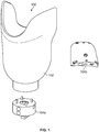
- vacuum suspended prosthetic device 100 may include socket 102 with an attached prosthetic limb (not shown) and electric vacuum pump 104a or 104b to evacuate air from within socket 102 to create a negative pressure (vacuum) between socket 102 and a user's residual limb (not shown), and thus suspend socket 102 from a user's residual limb.
- Vacuum suspended prosthetic devices are unique and customized to each user.
- a user of a vacuum suspended prosthetic device may be called a "user,” “patient,” and “amputee.” Because of the unique shape, geometry, and volume of each users residual limb, socket 102 may be customized for each user. Similarly, an amount of negative pressure provided by electric vacuum pump 104a, 104b to suspend socket 102 to a user's residual limb may also be unique for each user.
- prosthetic device may consult numerous times with a prosthetic user over the course of the user's lifetime and lifetime of the prosthetic device to constantly adjust the prosthetic device to provide the best fit and function of the prosthetic device.
- a consultation with a practitioner may include the practitioner adjusting vacuum suspension levels within socket 102 to find a suspension level that is both healthy and comfortable for a user's residual limb.
- increasing vacuum suspension level can correspond to an increase in amplitude of negative pressure or vacuum.
- decreasing vacuum suspension level can correspond to a decrease in amplitude of negative pressure or vacuum.
- a practitioner may have a user test a prosthetic device in different scenarios to determine a range of comfortable vacuum suspension levels without compromising the health of the user or function of the prosthetic device.
- Vacuum suspension technology has improved to include prosthetic sockets with adaptive vacuum systems that detect one or more activity levels of a patient and accordingly provide an appropriate amount of vacuum within the socket based on the current activity level of the patient.
- the present application appreciates that adaptive vacuum suspension control between a prosthetic socket and a patient's residual limb may be a challenging endeavor.
- a system for intelligent vacuum control can include a prosthetic socket, an electric vacuum pump, one or more sensors, a non-transient computer readable medium, and a processor.
- the electric vacuum pump can create a sub-atmospheric pressure within the prosthetic socket.
- the one or more sensors can sense an internal pressure of the prosthetic socket and data indicative of relative socket motion of the prosthetic socket.
- the non-transient computer readable medium can include program instructions and stiffness data. The stiffness data can correspond to a relationship between pressure variation of the internal pressure of the prosthetic socket and the relative socket motion of the prosthetic socket.
- the processor can be operatively connected to the electric vacuum pump, the one or more sensors, and the non-transient computer readable medium.
- the processor can execute the program instructions to automatically compare the data indicative of the relative socket motion of the prosthetic socket and the stiffness data.
- the processor can execute the program instructions to automatically determine a vacuum suspension range based upon the comparison of the data indicative of the relative socket motion of the prosthetic socket and the stiffness data.
- the processor can execute the program instructions to automatically actuate the electric vacuum pump.
- the internal pressure of the prosthetic socket can be adjusted to be within the vacuum suspension range.
- a method for intelligent vacuum control can include collecting, at one or more suspension levels, motion data of a prosthetic socket, data indicative of internal pressure of the prosthetic socket and data indicative of relative socket motion of the prosthetic socket with one or more sensors coupled to a prosthetic device.
- An activity level associated with the data indicative of the internal pressure of the prosthetic socket and the data indicative of the relative socket motion of the prosthetic socket can be determined via the motion data of the prosthetic socket.
- An electric vacuum pump can be actuated automatically with a processor operatively coupled to the electric vacuum pump.
- the internal pressure of the prosthetic socket can be adjusted to be within each of the one or more suspension levels, while the motion data of the prosthetic socket, the data indicative of the internal pressure of the prosthetic socket and the data indicative of the relative socket motion of the prosthetic socket are collected.
- a system for intelligent vacuum control can include a prosthetic socket, an electric vacuum pump, a pressure sensor, a non-transient computer readable medium, and a processor.
- the electric vacuum pump can create a sub-atmospheric pressure within the prosthetic socket.
- the pressure sensor can sense an internal pressure of the prosthetic socket and provide a pressure waveform indicative of relative socket motion of the prosthetic socket.
- the non-transient computer readable medium can include program instructions.
- the processor can be operatively connected to the electric vacuum pump, the one or more sensors, and the non-transient computer readable medium. The processor can execute the program instructions to automatically detect one or more peaks in the pressure waveform.
- the processor can execute the program instructions to automatically quantify the relative socket motion based upon the one or more peaks detected in the pressure waveform.
- the processor can execute the program instructions to automatically compare a magnitude of the one or more peaks that are detected to an acceptable value.
- the processor can execute the program instructions to automatically rate a quality of suspension during a step based upon the magnitude of the one or more peaks and the acceptable value that are compared.
- a method for intelligent vacuum suspension of a prosthetic socket can include: determining at least one activity level threshold between two or more activity levels; determining at least one vacuum suspension range for one or more activity levels; determining at least one residual limb motion threshold; real time monitoring of motion of the prosthetic socket; real time monitoring of a vacuum suspension level; and real time monitoring of residual limb motion.
- a method of qualifying and quantifying one or more steps taken by a prosthetic leg device using an intelligent vacuum suspension system during a gait cycle can include the steps of: real time monitoring of an internal socket pressure during the gait cycle for a step; determining a representative statistic of internal socket pressure during the gait cycle for a step, wherein the representative statistic includes one of an average, a median, a mode, or an root mean square; normalizing all or part of the real time monitored internal socket pressure against the determined representative statistic of the internal socket pressure to generate a normalized pressure data for a step; and qualifying each normalized pressure data against a threshold value to generate a step quality data for a step.
- a system for intelligent vacuum suspension of a prosthetic socket can include: a prosthetic socket; an electric vacuum pump for creating a sub-atmospheric pressure within a prosthetic socket; a processor operatively connected to the electric vacuum pump and operable to control the electric vacuum pump; a communication interface operatively connected to the processor and operable to provide a communication channel to the processor; a pressure sensor for sensing an internal pressure of the prosthetic socket, the pressure sensor operatively connected to the processor; a power source operatively connected to the system and operable to provide power to the system; and a non-transient computer readable medium containing program instructions for causing the processor to perform the method of detecting changes in prosthetic suspension stiffness.
- a method for determining fit of a prosthetic socket can include: using a pressure sensor to collect internal socket vacuum suspension level data; processing the collected internal socket vacuum suspension level data to determine each of: (1) a current vacuum suspension level; and (2) internal socket motion; comparing the current vacuum suspension level against a vacuum suspension level threshold for a given activity by a user; comparing the internal socket motion against a socket motion threshold value; and communicating an adverse condition when a threshold value is exceeded.
- a method for identifying one or more transitions in vacuum suspension stiffness at one or more specific temporal locations in a gait cycle for a vacuum suspended prosthetic socket can include the steps of: detecting one or more local peaks for a relative motion between a lower limb prosthetic socket and a residual lower limb during the one or more specific temporal locations in the gait cycle.
- a method for intelligent vacuum suspension of a prosthetic socket can include the steps of: determining at least one vacuum suspension range for one or more activity levels; determining at least one residual limb motion threshold; real time monitoring of a vacuum suspension level; and real time monitoring of residual limb motion.
- Any of the systems and methods shown and described herein can include the steps of: programming a processor of an intelligent vacuum suspension system with the determined at least one activity level threshold between the two or more activity levels, determined at least one vacuum suspension level range for the one or more activity levels, and the determined at least one residual limb motion threshold.
- any of the systems and methods shown and described herein can include the steps of: recording or sampling data associated with the real time monitored motion level; recording or sampling data associated with the real time monitored vacuum suspension level; and recording or sampling data associated with the real time monitored residual limb motion.
- any of the systems and methods shown and described herein can include the steps of storing at least one of: the recorded or sampled data associated with the real time monitored motion level; the recorded or sampled data associated with the real time monitored vacuum suspension level; and the recorded or sampled data associated with the real time monitored residual limb motion, for later evaluation by a user or practitioner.
- Any of the systems and methods shown and described herein can include the step of triggering an adaptive vacuum response when a value of the real time monitored motion level exceeds the determined at least one activity level threshold between the two or more activity levels.
- Any of the systems and methods shown and described herein can include the step of triggering an adaptive vacuum response when a value of the real time monitored vacuum suspension level exceeds the determined at least one vacuum suspension level range for the one or more activity levels.
- Any of the systems and methods shown and described herein can include the step of triggering a relative motion vacuum compensation response when a value of the real time monitored residual limb motion exceeds the determined at least one residual limb motion threshold.
- Any of the systems and methods shown and described herein can include the step of displaying data associated with at least one of: the real time monitored motion level; the real time monitored vacuum suspension level; and the real time monitored residual limb motion.
- Any of the systems and methods shown and described herein can include qualifying and quantifying one or more steps taken by a prosthetic leg device using an intelligent vacuum suspension system during a swing phase of the gait cycle.
- the swing phase can include an early swing phase, a mid-swing phase, and a late swing phase.
- Any of the systems and methods shown and described herein can include monitoring a vacuum waveform of the internal socket pressure for peaks in at least one of: an early portion, a middle portion, or a late portion of the vacuum waveform.
- the vacuum waveform can include a waveform including an early peak and a late peak.
- a maximum pressure of the late peak can be normalized against the determined average internal pressure to generate the normalized pressure data.
- Any of the systems and methods shown and described herein can include monitoring a vacuum waveform of the internal socket pressure.
- the vacuum waveform can include an augmented middle peak, and a pressure around a midway point of the augmented middle peak.
- the pressure around the midway point of the augmented middle peal can be normalized against the determined average internal pressure to generate the normalized pressure data.
- an ideal normalized pressure data can be about 1.
- the threshold value is ⁇ 1.5% of the ideal normalized pressure data.
- Any of the systems and methods shown and described herein can display in a graphical format at least one of: a pressure waveform of the monitored internal socket pressure, the determined average internal socket pressure during the swing phase of the gait cycle, and the step quality data.
- Any of the systems and methods shown and described herein can include the steps of sending the real time monitored internal socket pressure, the determined average internal socket pressure during the swing phase of the gait cycle, and the step quality data to a remote processor.
- any of the systems and methods shown and described herein can include an inertial sensing package.
- the inertial sensing package can include at least one accelerometer sensor.
- the inertial sensing package can include three accelerometer sensors.
- a first accelerometer sensor can be operable to measure acceleration in a x-direction relative to the prosthetic socket.
- a second accelerometer sensor can be operable to measure acceleration in a y-direction relative to the prosthetic socket.
- a third accelerometer sensor can be operable to measure acceleration in a z-direction relative to the prosthetic socket.
- the inertial sensing package can include at least one gyroscopic sensor.
- the inertial sensing package can include three gyroscopic sensors.
- a first gyroscopic sensor can be operable to measure rotation about a x-direction relative to the prosthetic socket.
- a second gyroscopic sensor can be operable to measure rotation about a y-direction relative to the prosthetic socket.
- a third gyroscopic sensor can be operable to measure rotation about a z-direction relative to the prosthetic socket.
- the communication interface can be a wireless communication interface operable to provide wireless communication to and from the processor.
- the fob can be operable to provide wireless communication to the communication interface and receive wireless communication from the communication interface.
- the processor can include a memory.
- the memory can be operable to store one or more programs for execution by the processor and store internal socket pressure data from the pressure sensor.
- Any of the systems and methods shown and described herein can include a graphical user interface operable to provide instructions to the processor.
- Any of the systems and methods shown and described herein can include a display for displaying a graphical user interface for providing instructions to the processor and displaying data sent from the processor.
- the adverse condition can be improper socket volume relative to a residual limb volume when the vacuum suspension level threshold is exceeded.
- the adverse condition adverse condition is improper socket shape relative to a residual limb shape when the socket motion threshold is exceeded.
- relative motion can be detected with a position sensor.
- the position sensor can be an inductive sensor.
- the position sensor can be a Hall sensor.
- relative motion can be detected by processing sampled data from a pressure sensor measuring an internal socket pressure.
- the sampled data can be processed from the pressure sensor measuring the internal socket pressure to evaluate one or more significant pressure deviations above an average pressure level during a swing phase of the gait cycle.
- the one or more significant pressure deviations can be evaluated by normalizing the one or more significant pressure deviations by the average pressure level during the swing phase of the gait cycle.
- the one or more significant pressure deviations can be evaluated by comparing the one or more significant pressure deviations to a threshold value.
- the sampled data can be processed from the pressure sensor measuring the internal socket pressure to evaluate significant pressure deviations from an average vacuum level during a stance phase of the gait cycle.
- the significant pressure deviations can be evaluated by normalizing the significant pressure deviations by the average vacuum level during the stance phase of the gait cycle and comparing a resultant normalized value to a threshold.
- the significant pressure deviations can be evaluated by comparing the significant pressure deviations to a threshold value.
- the residual limb motion can be monitored using a motion sensor.
- the motion sensor can include at least one of: a hall sensor, an inductive sensor, an ultrasonic sensor, and a force sensor.
- the residual limb motion can be monitored by processing pressure data from a pressure sensor in communication with an air space between a residual limb and a socket.
- pressure data can be processed by comparing an average of sampled data from one portion of a gait cycle to: one or more average values, one or more minimum values, or one or more peak values for one or more subsets of the averaged sampled data.
- vacuum suspension can be monitored during a swing phase of a gait cycle.
- the values of the gait cycle that are compared to a mean suspension level can be from at least one of: an early swing phase peak, a middle swing phase peak, or a late swing phase peak.
- the pressure data can be processed by comparing a root meet square (RMS) of sampled data from one portion of a gait cycle to one or more: RMS values, average values, minimum values, or peak values for one or more subsets of the root mean squared sampled data.
- RMS root meet square
- the vacuum suspension can be monitored during a stance phase of a gait cycle.
- vacuum suspension can be monitored during a heal strike transition or a toe off transition of a gait cycle.
- Any of the systems and methods shown and described herein can include the step of programming a processor of an intelligent vacuum suspension system with the determined at least one vacuum suspension level range for the one or more activity levels, and the determined at least one residual limb motion threshold.
- Any of the systems and methods shown and described herein can include the steps of: recording or sampling data associated with the real time monitored vacuum suspension level; and recording or sampling data associated with the real time monitored residual limb motion.
- the systems and methods shown and described herein can include the step of storing at least one of: the recorded or sampled data associated with the real time monitored vacuum suspension level; and the recorded or sampled data associated with the real time monitored residual limb motion, for later evaluation by a user or practitioner.
- Any of the systems and methods shown and described herein can include the step of triggering a relative motion vacuum compensation response when a value of the real time monitored residual limb motion crosses the determined at least one residual limb motion threshold.
- Any of the systems and methods shown and described herein can include the step of displaying data associated with at least one of: a real time monitored motion level; the real time monitored vacuum suspension level; and the real time monitored residual limb motion.
- the relationship between pressure variation of the internal pressure of the prosthetic socket and the relative socket motion of the prosthetic socket can be for a single patient at a single activity level.
- the one or more sensors comprise a pressure sensor.
- the data indicative of the relative socket motion of the prosthetic socket can be a pressure waveform provided by the pressure sensor.
- the processor can execute the program instructions to automatically: detect one or more peaks in the pressure waveform; and quantify the relative socket motion based upon the one or more peaks detected in the pressure waveform.
- an inertial sensing package can monitor motion of the prosthetic socket.
- the processor can execute the program instructions to automatically identify a gait cycle for a step from the motion of the prosthetic.
- the gait cycle can include phases.
- the one or more peaks can be correlated to each of the phases of the gait cycle.
- the at least one phase can include an early swing phase, a mid-swing phase, and a late swing phase.
- the processor can execute the program instructions to automatically normalize a magnitude of the one or more peaks of each of the phases into normalized values for each of the phases. The normalized values for each of the phases can be combined into a sum.
- the processor can execute the program instructions to automatically qualify the vector sum of the step against a threshold value.
- a step quality value can be generated for the step.
- a communication interface can be in communication with the processor. The processor can execute the program instructions to automatically transmit the step quality value, the vector sum, the normalized values, the pressure waveform, or a combination thereof via the communication interface.
- the processor can execute the program instructions to automatically normalize the one or more peaks into a normalized value.
- the normalized value of the one or more peaks can be compared with a socket motion threshold value.
- the one or more peaks can be normalized into the normalized value using a pressure statistic of at least a portion of the pressure waveform.
- the pressure statistic can include an average, a median, a mode, a root mean square, or a combination thereof.
- the processor can execute the program instructions to automatically communicate an adverse condition when the socket motion threshold value is exceeded.
- an inertial sensing package can monitor motion of the prosthetic socket.
- the processor can execute the program instructions to automatically determine an activity level based upon the motion of the prosthetic socket.
- the vacuum suspension range can be determined based in part upon the activity level.
- the inertial sensing package can include at least one accelerometer sensor, at least one gyroscopic sensor, at least one force sensor, at least one pressure sensor, or a combination thereof.
- the one or more sensors can include a motion sensor that directly senses the relative socket motion of the prosthetic socket.
- the motion sensor can include at least one of a hall sensor, an inductive sensor, an ultrasonic sensor, and a force sensor.
- a step can be identified via the motion data of the prosthetic socket.
- the step can be correlated to the data indicative of relative socket motion of the prosthetic socket.
- the data indicative of relative socket motion of the prosthetic socket that is correlated to the step can be normalized into normalized data.
- the step can be classified according to the normalized data.
- the data indicative of the internal pressure of the prosthetic socket and the data indicative of the relative socket motion of the prosthetic socket can be compared to expected level of vacuum data.
- the expected level of vacuum data can correspond to the activity level associated with the data indicative of the internal pressure of the prosthetic socket and the data indicative of the relative socket motion of the prosthetic socket.
- the expected level of vacuum data can include pressure data and relative socket motion data corresponding to a proper fit.
- a fit of the prosthetic socket can be evaluated based upon a mismatch of the data indicative of the internal pressure of the prosthetic socket and the data indicative of the relative socket motion of the prosthetic socket compared to the expected level of vacuum data.
- a graphical user interface can be provided upon a display operatively connected to a remote processor driven device.
- the remote processor driven device can be in communication with the processor.
- the graphical user interface can present at least one of the motion data of the prosthetic socket, the data indicative of the internal pressure of the prosthetic socket and the data indicative of the relative socket motion of the prosthetic socket.
- Suspension level input can be received via the graphical user interface.
- One or more of the multiple suspension levels can be changed based upon the suspension level input.
- the processor can execute the program instructions to automatically select a vacuum suspension range.
- the selection can be at least partially informed by the quality of the suspension.
- the processor can execute the program instructions to automatically actuate the electric vacuum pump.
- the internal pressure of the prosthetic socket can be adjusted to be within the vacuum suspension range.
- Any of the systems and methods shown and described herein can include a display operatively connected to a remote processor driven device.
- the remote processor driven device can be in communication with the processor.
- the remote processor driven device can automatically receive the quality of the suspension from the processor.
- the remote processor driven device can automatically provide a graphical user interface upon the display.
- the graphical user interface can be configured to evaluate or tune operation of the electric vacuum pump.
- the processor can execute the program instructions to automatically store the quality of the suspension to the non-transient computer readable medium.
- Adaptive vacuum suspension using an intelligent vacuum suspension control improves upon existing adaptive vacuum suspension control by providing enhanced adaptive vacuum control and providing vacuum suspension feedback diagnostics to a practitioner/prosthetist.
- intelligent vacuum suspension control may be incorporated into existing vacuum suspension systems 100 using socket 102 and electric vacuum pump 104a and 104b.
- Vacuum pump 104a may be in line with socket 102 and prosthetic limb (not shown).
- vacuum pump 104b may be mounted on a side of socket 102. Further, the pump might be mounted on another location of the prosthesis such as the pylon or foot.
- Both vacuum pump 104a and 104b provide evacuation of air within socket 102 to create a negative pressure (vacuum) and suspend socket 102 from a user's residual limb.
- a vacuum pump for evacuating air from socket 102 need not be limited to embodiments illustrated by vacuum pump 104a and 104b and a vacuum pump may be of any design or location on, in, or remote from socket 102.
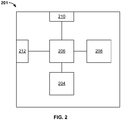
- Intelligent vacuum suspension system 201 may include a CPU, microprocessor, or other processor 206 operable to: be programmed to accept one or more signal inputs; process one or more signal inputs based on instructions stored in a memory of processor 206; and provide one or more output signals based on processed input signals.
- Intelligent vacuum suspension system 201 may further include one or more sensors 208, vacuum pump 204, communication interface 210, and power source 212, all operatively connected to processor 206.
- Sensors 208 may include any or all of gyroscopic sensors, accelerometers, induction sensors, magnetometers, hall sensors, optical sensors, pressure sensors, temperature sensors, and like sensors. Sensors 208 may be operable to take one or more data readings of one or more conditions (i.e. pressure, acceleration, velocity, displacement, orientation, momentum, magnetic field, inductance, etc.), both discretely and continuously, to provide one or more input signals to processor 206. Vacuum pump 204 may be actuated and controlled by processor 206 in response to an input from sensors 208, based on programming of processor 206, in response to other signals received and processed by processor 206 (i.e.
- Communication interface 210 may be used to communicate with processor 206 to provide further input/output to processor 206 and act as a communication channel to/from processor 206.
- Communication interface 210 may be a hardwired connection such as: a USB connection connected via a USB cable, or serial connection connected via a serial cable, or an Internet connection using an Ethernet cable; a transceiver capable of wirelessly transmitting and receiving signals to and from processor 206 which may include use of WiFi and other 802.11 standards, Bluetooth ®, cellular communications, and the like; an input/output pin or other electrical connection to processor 206 capable of inputting or outputting a signal to and from processor 206; a slot or drive capable of processing a memory device or computer readable media such as an optical medium (i.e. compact disc, Blu-ray, and the like), magnetic media (floppy disk, hard disk, and the like), solid-state drive, memory card, and the like.
- an optical medium i.e. compact disc, Blu-ray, and the like
- magnetic media floppy disk, hard disk, and the like
- solid-state drive memory card, and the like.
- communication interface 210 may further process data so as to encrypt data prior to communicating data from processor 206 to another device.
- Communication interface 210 may also communicate data as a text message (SMS), audio signal, video signal, or any combination thereof.
- communication interface 210 may include more than one interface such as a main communication interface 210 and intermediary communication interfaces 210.
- Power source 212 may be any known power source used to power processor 206 such as one or more batteries, capacitors, a hard wired power connection, or a generator.
- Processor 206 may include additional memory for storing instructions, accumulated data, and the like.
- Processor 206 is capable of reading and executing any non-transient, computer readable medium containing program instructions for performing any of the methods disclosed herein, such that system 201 is operable to perform the methods as disclosed herein.
- GUIs 314 may be used to provide initial parameters and initialize processor 206 for intelligent vacuum suspension system 201.
- GUIs 314 may be implemented on any remote processor driven device with a display such as a computer, smart phone, tablet, remote control, fob, and the like.
- GUI 314 is only available to a practitioner for customizing and programming vacuum suspension parameters, checking diagnostics and adverse condition alerts, and communicating to and from processor 206 of intelligent vacuum suspension system 201.
- a user can access GUIs 314 to provide input parameters to, and check diagnostic messages from intelligent vacuum suspension system 201.
- remote access by the practitioner or manufacturer could be used to assist or train the user or service the suspension system.
- GUI 314 hardware from the aforementioned processor driven devices and software of GUI 314 may send input parameters entered into GUI 314 to communication interface 210 which transfers input parameters to processor 206 for control of vacuum pump 204.
- data output from processor 206 via communication interface 210 may be received by hardware on a remote processor driven device, and software of GUI 314 may process output data from processor 206 for display on GUI 314.
- example GUIs 314 are illustrated.
- an example initialization GUI 314 is provided for a practitioner to enter input parameters.
- Suspension level (set point/upper set point/USP) 318 may be set, and a suspension range 320 may be provided for suspension level 318.
- Suspension range 320 may be employed to provide a functional suspension level for an activity while conserving system power, and minimizing the number of activations of the pump which can result in excessive distractions for the user.
- a practitioner and user may indicate that a vacuum level of 12 inHg to 18 inHg may provide sufficient suspension for an activity such as walking.
- Range 320 for this activity may be communicated to processor 206 and vacuum pump 204 may remove air from within socket 102 until a vacuum suspension level of 18 inHg, the upper set point, or set point 318 is achieved.
- the vacuum suspension level within socket 102 will continually and slowly decrease during use of prosthetic device 100, typically due to leaks through imperfections in one or more seals of socket 102.
- range 320 may be provided to allow for a reduction in vacuum suspension level to a lower set point 319 of 12 inHg before actuating vacuum pump 204 to restore suspension levels to upper set point 318.
- a maximum set point 322 may be a practitioner and/or user defined maximum value that provides suspension while still being comfortable for a user. Suspension levels past maximum set point 322 may cause discomfort to a user and negatively affect circulation within the user's residual limb. Suspension levels below lower set point 319 may allow cyclical or other undesirable movement of socket 102 relative to a user's residual limb. These lower vacuum levels can correspond to a risk of excessive displacement of socket 102 relative to a user's residual limb.
- Battery indicator 324 may show a level of charge or power available to power source 212.
- a patient may move or walk or otherwise travel through their environment with a range of intensities, speeds, or cadences thus exposing a prosthetic device to different combinations of accelerations and/or rotations at these various types of activity.
- a patient's given speed, cadence, pattern, or intensity of activity while using a prosthetic device may be known as a "level of activity” or an "activity level.”
- GUI 314 illustrates an example adaptive vacuum GUI 426 for setting ranges 420a and 420b for two or more activity levels 428a and 428b.
- each activity level 428a and 428b may include its own vacuum suspension level set point 418a, 418b, lower set point 419a, 419b, and range 420a, 420b.
- a user maximum set point 322 and charge indication 324 may also be provided.
- Indicator arrow 430 may output pressure data from sensor 208 to indicate a current vacuum suspension level within socket 102 in real time.
- sensor 208 may also include an inertial sensing package to monitor motion of prosthetic socket 102, and accordingly motion of a user.
- the inertial sensing package can comprise at least one accelerometer sensor, at least one gyroscopic sensor, at least one force sensor, at least one gyroscope, at least one pressure sensor, or a combination thereof.
- the inertial sensing package can be configured to sense data along multiple dimensions, i.e., two dimensional data, three dimensional data or the like.
- inertial sensing package 208 may include 3 accelerometers with a first accelerometer sensing acceleration data in a x direction relative to prosthetic device 100, a second accelerometer sensing acceleration data in a y direction relative to prosthetic device 100 and a third accelerometer sensing acceleration data in a z direction relative to prosthetic device 100.
- Data sensed by each accelerometer may be squared and added together to give a scalar value of a square of the magnitude.
- Intrinsic functions such as taking a square root of a number may be cumbersome for small microprocessors such as might be employed as processor 206. Accordingly, a square of a magnitude may be used interchangeably with a magnitude since both will be monotonic increasing functions.
- Magnitude data from inertial sensing package 208 may be more easily processed and stored by processor 206 since use of a magnitude eliminates issues such as orientation of sensors 208 and/or prosthetic device 100. Accordingly, data from inertial sensing package 208 may be used to sense different activity levels 428a and 428b with processor 206 and communication interface 210 processing and sending activity level data to a remote processor driven device for display on GUI 426.
- Different activity levels 428a and 428b may correspond to any of a variety of activity levels, including for example moving and resting, respectively. Possible activity levels that may be processed include, for example, sitting, resting, standing, walking, jogging, sprinting, jumping, and the like. Any number of activity levels 428a and 428b may be processed by processor 206. GUI 426 may provide a graphical representation of activity level 428a and 428b.
- range 420a or 420b and set point 418a or 418b data may be entered into GUI 426 and communicated to processor 206, so that when inertial sensing package 208 senses accelerations or rotations and transfers this data to processor 206, processor 206 may then convert this motion information into a measure of activity and subsequently actuate electric vacuum pump 204 to obtain a desired vacuum suspension level 418a or 418b based on an activity level. Accordingly, providing processor 206 with vacuum ranges 420a, 420b and set point 418a, 418b data for two or more activity levels 428a and 428b, and one or more activity thresholds 536, provides a level of adaptive vacuum for intelligent vacuum suspension system 201.
- the motion of prosthetic socket 102 detected by the inertial sensing package 208 can be utilized to identify a gait cycle for each step taken by the user.
- the gait cycle can comprise two major phases - a stance phase and a swing phase.
- the stance phase can correspond to the portion of the gait cycle where the prosthetic device 100 contacts a walking surface.
- the stance phase can span from a heel strike, where the heel of the prosthetic device 100 first contacts the walking surface during the step, to a toe off, where the toe of the prosthetic device 100 last contacts the walking surface during the step.
- the stance phase can furthermore comprise a single support phase.
- the weight of the user can be substantially completely supported by the prosthetic device 100, i.e., the other leg can be out of contact with the walking surface.
- the swing phase can span from the toe off to a heel strike of the subsequent step.
- the prosthetic device 100 can be out of contact with the walking surface.
- the gait cycle can be divided at specific temporal locations.
- the swing phase can start after the toe off event and be comprised of an early swing phase, a mid-swing phase, and a late swing phase, and then end with the heel strike event. Accordingly, the gait cycle can be correlated with other data collected by the prosthetic device 100 via particular phases, temporal locations, and the like.
- Activity threshold GUI 532 may be used by a practitioner or user to monitor activity data 534 for different activity levels 428a and 428b and set an activity threshold 536.
- Activity threshold 536 may be used by processor 206 for adaptive vacuum control. If inertial sensing package 208 senses an activity level above or below this threshold, processor 206 may actuate electric vacuum pump 204 to adjust a vacuum level within socket 102 to a proper suspension level 418a, 418b based on sensed activity level. While two activity levels 428a and 428b are illustrated for exemplary purposes, intelligent vacuum suspension control may be modified to include numerous activity levels.
- GUI 532 may use a slider bar 538 to set activity threshold 536 or simply allow a graphical level bar on the plot of GUI 532 to be grabbed and moved with a cursor. In addition to the these methods allowing the practitioner or user to select an activity threshold, the GUI can also suggest or select a threshold based on calculations utilizing the activity data 428a and 428b.
- GUI 314 illustrating an example data analysis and diagnostic GUI 640 is illustrated.
- a practitioner or user may be able to select a date range at 642 to limit data to a specific time frame.
- Other status indicators such as charging 644, leaks 646, battery 648, seal quality 650, and relative limb motion 652 may be used with normal operation indicated by a check 654 for each.
- GUI 640 may allow for more in depth analysis of each category, for example, by clicking a mouse, keyboard, or other input device on a specific category if a problem has been indicated.
- An indication of problems may be shown by symbolic representation such as an exclamation point (!) 656, different color text, or dialog box 657.
- socket motion may be a serious adverse condition that may affect suspension of socket 102 from a user's residual limb, and impair a user's proprioception such that the user is less aware of the spatial orientation and movement of a prosthetic device.
- a properly evacuated socket that is a socket with proper vacuum suspension level, may help to maintain both residual limb volume over time, and proper contact between the residual limb and the socket by creating an appropriate level of suspension force and thereby greatly reducing a tendency of a residual limb to move within a prosthetic socket.
- Predefined set points 418a/418b, 419a/419b, and 420a/420b for various activity levels 428a, 428b may not adequately address adverse conditions arising from change in volume to a user's residual limb. As such, additional information about, and greater control of adaptive vacuum suspension levels may be necessary to provide more appropriate prosthetic suspension.
- sensor 208 within socket 102 may be used to sense residual limb motion within socket 102 and enable processor 206 to adjust a vacuum level therein to correct or compensate for socket motion.
- This additional level of vacuum compensation may be referred to as relative motion compensation or socket motion compensation.
- a map of activity level vs. vacuum level may be constructed and referenced to allow for quicker vacuum adjustments during either real time adaptive vacuum control, or diagnostic use by a practitioner.
- a motion sensor 208 may be comprised of a Hall sensor placed in a base of a prosthetic socket and a small magnet fastened to a tip of a prosthetic liner worn over a user's residual limb.
- a motion sensor 208 may be comprised of a mutual inductance device that measures a mutual inductance between a coil in a base of a prosthetic socket, and a small coil or conductive target placed on a tip of a prosthetic liner worn over a user's residual limb.
- a metallic or otherwise conductive thread sewn into an end of a residual limb liner in conjunction with an inductance sensor 208 in socket 102 of a prosthetic device 100 may also be used to sense motion of a residual limb relative to prosthetic socket 102.
- a motion sensor 208 is comprised of an ultrasonic sensor 208 that may be tuned to detect a target mounted on a tip of a prosthetic liner worn over a user's residual limb where said target is chosen to have an appropriate acoustical impedance to efficiently reflect a relevant acoustical signal. Placing ultrasonic sensor 208 in a prosthetic socket 102 may also directly detect a residual limb or prosthetic liner.
- a motion sensor 208 includes a force sensor 208 placed in a bottom of a prosthetic socket 102. Intermittent contact of a user's residual limb with a force sensor 208 may indicate an occurrence of residual limb motion within socket 102. Use of aforementioned sensors 208 may indicate motion of residual limb within socket 208, but data from a single inductive sensor 208 may or may not allow for characterization of residual limb motion relative to socket 102. Such characterization may require multiple sensors depending on placement.
- a pressure sensor 208 may also be used to sense motion of a user's residual limb relative to socket 102, characterize the type of motion, and provide feedback data for either real time adaptive vacuum control, or diagnostic use by a practitioner.
- socket 102 may be thought of as a sealed vessel
- the Ideal Gas Law may be used to approximate internal socket pressure and socket motion relative to a user's residual limb
- PV nRT
- P an internal socket pressure of socket 102
- V a volume of air between socket 102 and a patient's limb or liner
- n an amount of air in socket 102
- R the ideal gas constant
- T a temperature of air within socket 102.
- Both n and R may be assumed to be fixed values and T may be unlikely to change significantly after socket 102 has been worn for a period of time such as, for example, several minutes or about 10 minutes. This assumption of isothermal performance is a reasonable approximation of an actual system.
- socket 102 may be modeled as a closed system and Equation 1 may be simplified to Boyle's law where: P ⁇ 1 V where P , internal socket pressure of socket 102, is inversely proportional to V, a volume of air between socket 102 and a liner or residual limb. Use of this relation may be used to sense motion of a user's residual limb within socket 102. Further, pressure data and graphical representations of pressure data may be used to characterize socket motion both for purposes of adaptive vacuum suspension level control and to provide a practitioner with a visual feedback for detecting, characterizing, and correcting socket motion.
- graph 758 illustrates pressure waveforms for variations in vacuum pressure while walking at several different vacuum suspension levels.
- Waveform 760 showing vacuum pressure level variations within socket 102 at a suspension level of 18 In Hg shows a relatively symmetrical waveform similar to a sine wave.
- Waveform 762 showing vacuum pressure level variations within socket 102 at a suspension level of 8 In Hg, similar to waveform 760, shows a relatively symmetrical waveform similar to a sine wave, but with an increase in amplitude.
- Waveform 764 showing vacuum pressure level variations within socket 102 at a suspension level of 4 In Hg shows an irregular waveform with an increase in amplitude with early and late peaks in the waveform.
- Waveform 766 showing a vacuum pressure level variation within socket 102 with bare minimum suction shows an irregular waveform with a higher amplitude than the others with early and late peaks. Accordingly, shapes of waveforms associated with vacuum pressure variation may be used to classify a type of socket motion relative to a user's residual limb. Pressure variation data associated with each waveform may trigger an adaptive vacuum response from processor 206.
- example types of motion 868 and 874 between a user's residual limb 876 and socket 102 are illustrated.
- Different vacuum suspension levels may cause socket motion characterized by: (1) a linear motion 874 of a user's residual limb 876 relative to socket 102 which may be characterized as "pistoning" 874, as this motion mimics a movement of a piston in a cylinder; and (2) a rotational motion 868 of user's residual limb 876 relative to socket 102 which may be characterized as "rocking" 868, as this motion mimics a backwards and forward rocking motion.
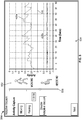
- FIG. 9 a graph showing an example effect of vacuum level on pressure/motion profile is illustrated.
- data points for variations in vacuum are plotted against socket motion (distance) for a single patient at a single cadence.
- slopes of the two lines 980 and 982 illustrated in FIG. 9 are given by pressure/distance which gives a corresponding stiffness value.
- the stiffness factor for high vacuum levels shows little motion for a corresponding change in vacuum level as represented by line 980.
- This stiffness represented by a slope of line 980 is about fivefold that for lower vacuum suspension levels which permit increased socket motion for similar changes in socket pressure as represented by line 982.
- the two lines 980 and 982 can be formed by collecting data points for a user for a given cadence or activity level. For a specific activity level, variations in vacuum and socket motion can be observed at known vacuum suspension levels, which are represented in FIG. 9 by circular regions surrounding data points. Specifically, the two lines 980 and 982 were generated by observing variations in vacuum and socket motion at vacuum suspension levels of 20 in Hg, 14 in Hg, 8 in Hg, and passive suction. The process can be repeated for a desired number of activity levels, which can be determined as described herein.
- the stiffness data can comprise one or more sets of data (e.g., lines) that each correspond to a different activity level.
- the stiffness data can be stored in memory that can be accessed to control vacuum suspension level. It is noted that, while stiffness is depicted as lines 980 and 982, the stiffness data can be stored in memory in any machine readable format such as, but not limited to, look-up tables, equations, curves, boundary conditions, logical rules, an inflection point and the like. Further, simply storing the minimal vacuum level necessary to provide high stiffness suspension at a given activity level is sufficient for such a record.
- the stiffness data can be collected while the socket 102 is properly fitted to the residual limb 876.
- the stiffness data can be utilized to evaluate fit problems associated with changes in the geometry of the residual limb 876 and the socket 102.
- the residual limb 876 can change in shape, volume or both to create a mismatch with the socket 102.
- the geometry of the socket 102 can change in shape, volume or both due to fatigue or acute damage. Since the residual limb 876 can be obscured by the socket 102, such changes can be difficult to observe. This can be further complicated by the losses of sensation in a residual limb often associated with injury or vascular disease.
- the stiffness data can correspond to a relationship between variations in vacuum and the socket motion. Without being bound to theory, it is believed that the stiffness can correspond to the interaction of the residual limb 876 and the socket 102. Specifically, high stiffness can correspond to a relatively large amount of resistance to relative motion, corresponding to solid contact with the residual limb 876. Likewise, low stiffness can correspond to a relatively small amount of resistance to relative motion due to less solid contact with, or even separation from, the residual limb 876. Applicants have discovered that the stiffness can by represented line 980 (high stiffness) and line 982 (low stiffness), which provide a discontinuity in the stiffness that demarcates a high stiffness region and a low stiffness region. Specifically, line 980 has a relative large slope compared to line 982. Lines 980 and 982 can form a "knee" or "bend" in the continuum of stiffness data.
- the regions of low stiffness data can be correlated to socket motion and can therefore be utilized to predict and mitigate undesired socket motion.
- a relatively large variation in vacuum can correspond to a relatively small amount of socket motion.
- the residual limb 876 can be providing a relatively large amount of resistance to deformation, which can be correlated with a low amount of socket motion.
- a relatively small variation in vacuum corresponds to a relatively large amount of socket motion.
- the residual limb 876 can be providing a relatively small amount of resistance to deformation, which can be correlated with a high amount of socket motion.
- the stiffness data can be utilized to determine a vacuum suspension range. For example, the lowest suspension level necessary to remain on the high stiffness can be determined for a given patient at one or more activity levels. The patient's activity level can then be compared to this table and an appropriate level of suspension can be selected to keep the patients suspension in the region of high stiffness. Should the current combination of vacuum suspension range and activity level correspond to a region of low stiffness represented by line 982, a new vacuum suspension range that corresponds to a region of high stiffness represented by line 980 can be selected.
- the forces in the swing phase can be considered as consistent from step to step. Accordingly, an assumption of consistent force or loading can be utilized to apply stiffness data.
- the stiffness data can identify some minimum level of vacuum for the high stiffness region (e.g., an inflection point), which could be treated as a desired level of vacuum.
- the activity level can be utilized to determine an appropriate suspension level from the stiffness data.
- peaking can be detected and can be utilized as an indirect indication that the stiffness data has broken down. That is, peaking can be an independent artifact indicative of operation in a region of low stiffness. Accordingly, peaking can be utilized to determine an appropriate suspension level without knowledge of cadence or activity level. It is furthermore noted, that a shift in the minimum level of vacuum for the high stiffness region can be indicative of a change in fit between the residual limb 876 and the socket 102.
- sample pressure waveforms indicative of certain socket motion types 868 and 874 are illustrated.
- the pressure waveforms, or any portion thereof can be correlated to the gait cycle, as described above, to analyze the pressure waveforms.
- waveform 1084 shows a shape profile suggesting pistoning-type socket motion 874
- waveform 1086 shows a shape profile suggesting rocking type socket motion 868.
- Pistoning 874 may occur when a vacuum level of an interior of socket 102 is not great enough to adequately secure socket 102 of prosthetic device 100 to residual limb 876 and may be caused by forces such as gravity and radial force (i.e.
- socket 102 may act to pull socket 102 from a user's residual limb 876 while prosthetic device is in use (i.e. during a swing phase of ambulation).
- Rocking 868 may occur at vacuum levels insufficient to maintain rigid suspension during acceleration and deceleration of a residual limb at a start and end of the swing phase of the gait cycle. While a vacuum level within socket 102 may be sufficient to overcome forces that may cause pistoning 874, motional forces (i.e. tangential force, torque, etc.) may still act upon socket 102 to cause rocking 868.
- Waveform 1086 Early and late peaking occurring on waveform 1086 is indicative of relative motion between the residual limb and the socket due to an imbalance of forces on socket 102 during a beginning 870 and end 872 of the swing phase of the gait cycle.
- Data points from a collection of waveforms similar to FIG. 7 taken at a range of vacuum levels and a single cadence or activity level may be further processed to provide an activity threshold value for adaptive vacuum control at that cadence or activity level.
- a maximum late peak value 1088 may be taken for each step and normalized against an average swing phase vacuum suspension level for each step.
- Determination of a "late peak” waveform may be conducted by comparing the maximum amplitude during some fraction of the later portion of the swing phase portion of waveform 1086 with the average amplitude of the swing phase portion of waveform 1086. Where the peak amplitude of the late portion of the swing phase is higher than the average amplitude of the wave, a "late peak” waveform may be identified.
- normalization of a maximum late peak value 1088 against average vacuum suspension level during the swing phase of the gait cycle for each step gives a value close to 1.00 (one) when there is little late peaking, and values greater than 1.00 (one) are indicative of a late peak in an associated step.
- Center peaking characterized by an augmented center peak 1090 on waveform 1084 may be indicative of relative motion between a user's residual limb and socket 102 due to an imbalance of forces acting on socket 102 during a midpoint 878 of the swing phase of the gait cycle.
- finding a minimum value of some center portion of the swing phase will capture a value at point 1092 from some portion of the augmented center peak 1090 and therefore yield a value greater than the average amplitude of the swing phase of waveform 1084. While simply detecting the peak value of some middle portion of the swing phase is somewhat accurate, this improved method of detecting a center peak value has the advantage of not capturing portions of a late peak that might overlap the center portion of the swing phase.
- normalization of a central minimum value 1092 of augmented center peak 1090 against average vacuum suspension level during the swing phase of the gait cycle for each step gives a value close to 1.00 (one) and values greater than 1.00 (one) are indicative of a center peak in the associated step.
- Peaks in locations other than the swing phase of a of gait may be detected in a similar manner, normalized by an average motion or pressure in some other portion of the gait cycle, and may be useful in evaluating a patient's suspension.
- similar measures could, in this way, be extracted from the stance phase or the heel strike or toe off transitions of gait.
- Deviations of normalized data from 1.00 may be compared to a preset threshold for socket motion (i.e. a socket motion threshold) and used to trigger a vacuum level response (i.e. relative motion compensation) when normalized data exceeds the preset socket motion threshold.
- a preset threshold for socket motion i.e. a socket motion threshold
- This threshold may be patient dependent and may be affected by socket geometry, socket size, patient tissue type, patient cadence or activity, and other factors.
- a socket motion threshold of ⁇ 1.5% of a normalized value from the average swing phase vacuum level has been found to be useful. In this manner, detection of steps with relative socket motion exceeding a threshold may provide an instant, real time adaptive vacuum level response to socket motion.
- method 1100 may include the following steps.
- One or more activity thresholds that divide two or more activity levels can be determined ( 1101 ).
- An initial vacuum suspension level range can be determined for the one or more activity levels ( 1103 ).
- a residual limb motion threshold can be determined ( 1105 ).
- An activity level can be monitored in real time to compare the activity level to one or more activity levels of a user.
- the method 1100 may include the step of monitoring an activity level in real time, comparing the activity level to one or more activity levels of a user, and adjusting a vacuum suspension level ( 1107 ).
- the vacuum suspension level can be adjusted when a monitored activity level exceeds a determined activity threshold. Data related to a monitored activity level can be recorded. Accordingly, the adaptive vacuum ( 1107 ) can adjust the suspension level when the monitored activity level is outside of the range set by the determined activity threshold.
- the determined activity threshold can comprise a high activity level and a low activity level that corresponds to the current suspension setting. When the monitored activity level falls outside of the range defined by the high and low activity levels, the vacuum suspension level can be adjusted to be within the range. Thus, the vacuum level can be increased when a user becomes more active and decreased when a user returns to a lower level of activity.
- the control method 1100 can further comprise monitoring a vacuum suspension level in real time and adjusting a vacuum suspension level if a monitored vacuum suspension level falls outside the current vacuum suspension level range and recording data related to a monitored vacuum suspension level ( 1109 ); and monitoring residual limb motion in real time and adjusting a vacuum suspension level when a monitored residual limb motion exceeds a determined residual limb motion threshold and recording data related to monitored residual limb motion ( 1111 ).
- Control method 1100 combines traditional fixed vacuum suspension control ( 1109 ) with adaptive vacuum ( 1107 ) and relative motion compensation ( 1111 ). While this layering of control methodologies has been found to be useful, implementation of relative motion compensation does not require the use of these other methods of control.
- steps may be evaluated based on variations in pressure data and socket motion associated therewith and this information may then be either used to adjust a level of vacuum in the socket, or simply logged according to a hierarchy such as "no motion,” "motion,” and “marginal.” While this example allows for 3 discrete ranges of motion, the results of such an evaluation may be subdivided into any number of ranges, or might be logged by independent motions and not a combination of motions such as that generated by the sum of squares process discussed earlier. In contrast to sorting into ranges, actual deviations or motion values may also be saved.
- Logged step data may be later retrieved and evaluated by a practitioner during a consultation with a user or by the user.
- logged steps may be periodically sent from processor 206 via communication interface 210 to a practitioner or user using hardware discussed above.
- logged steps may be periodically sent from processor 206 via communication interface 210 to an intermediary storage such as hard drive or cloud storage to be accessed by a practitioner or user.
- An evaluation of steps may also be sent to a user via communication interface 210 if a socket motion threshold is exceeded for a signification portion of steps taken by the user.
- An evaluation of steps may be sent as a message, an audio message, a visual display, and the like.
- An evaluation of steps may also be displayed to a practitioner or user in real time for evaluating vacuum suspension levels for a user.
- Real time evaluation of steps may allow a practitioner to make real time adjustment to vacuum suspension levels and evaluate a fit of socket 102.
- Step classification 1294 may provide various indicia 1296 corresponding to how each step is classified.
- indicia 1296 may use different colors, shapes, fills, and the like to represent aforementioned step hierarchy and socket motion type.
- boundary 1298 appears to be an ellipse due to different scales on the two axes, in this embodiment, this boundary is actually a circle.
- Steps shown outside circle 1298 may indicate steps with significant or undesirable amounts of relative socket motion.
- Step classification GUI 1300 may provide a practitioner or user with graphical representations of pressure sensor data such as pressure wave form 1302, motion 1304 and step classification 1306.
- method 1400 may include the steps of monitoring an internal socket pressure in real time during a swing phase of a user's gait cycle for each step taken ( 1401 ); collecting a series of monitored internal socket pressure readings during a swing phase of a user's gait cycle for each step taken ( 1403 ); calculating an average internal socket pressure during a swing phase of a user's gait cycle for each step taken ( 1405 ); normalizing one or more portions of all or part of collected pressure waveform data against a calculated average internal socket pressure during the swing phase to generate a normalized pressure value for each step taken during a particular portion of the gait cycle ( 1407 ); combining one or more measures of internal socket motion by calculating a vector sum ( 1408 ), qualifying each combined measure of socket motion against a threshold value to generate a step
- a motion or pressure sensor 208 in intelligent vacuum suspension control 200 may be used to detect and characterize socket motion of socket 102 relative to a user's residual limb 876, this data may also be used to evaluate and track a fit of prosthetic socket 102.
- a proper shape and size of prosthetic socket 102 may be two important factors in determining proper socket fit.
- a socket 102 of proper size and shape will limit socket motion at relatively low levels of vacuum suspension. Accordingly, this low level of vacuum may be characterized at the time of fitting, or a predictive algorithm may be employed to predict the necessary level of suspension necessary for a particular user and socket 102. The level of suspension necessary to limit socket motion can then be monitored and compared to this expected level of vacuum for indications of issues with socket fit.
- Socket 102 with a proper shape and improper size-that is, shaped correctly based on a user's residual limb 876, but of an improper volume, will have a tendency to produce pressure data characterized as showing little to no internal socket motion, but requiring vacuum suspension levels higher than those necessary with a proper fit for a given activity level. This necessary level of vacuum might be described as uncomfortable or even painful by the user depending on the degree to which the size is mismatched. Additionally, socket 102 with proper size and an improper shape will typically exhibit internal socket pressure data that suggests a need for both higher than necessary vacuum suspension level while still exhibiting increased socket motion.
- socket 102 may accommodate a correct volume of a user's residual limb 876, but is shaped improperly relative to a user's residual limb 876.
- vacuum suspension levels higher than necessary for a properly fitting socket 102 may negatively affect a user's residual limb 876 potentially inducing injury if the fit is sufficiently incorrect.
- An ability to detect improper fit for socket 102 may be used to monitor socket fit and indicate to the user and/or practitioner that a fit of socket 102 may be inappropriate and should be evaluated to prevent any negative effects. This process may be used both acutely, during a fitting of socket 102 in the practitioner's office, or to monitor socket fit over long periods of usage by the patient.
- Method 1500 may include the steps of collecting and processing pressure sensor data across a range of vacuum levels and cadences or activity levels during gait ( 1501 ). Evaluating an amount of motion detected during gait at each level of vacuum, and then comparing amount of motion detected to an amount of vacuum that would be expected to be necessary to stabilize a specific patient's prosthesis 100 (assuming that the prosthesis may be suspended at a comfortable or achievable level of vacuum) ( 1503 ).
- Method 1600 may include the steps of having a patient move about (i.e. test movement) in a well-fitting socket at both a range of vacuum suspension levels and a range of cadences or activity levels ( 1601 ). Collecting socket motion data during patient test movement ( 1603 ). Constructing a curve based on collected socket motion data of a level of vacuum necessary to stabilize a patient's prosthesis as a function of activity level or cadence ( 1605 ). Recording or storing the curve for use by processor 206 ( 1607 ).
- analysis of vacuum waveforms may be used to evaluate motion of socket 102 during various portions of the gait cycle. This information may be used to assist in tuning functionalities of a patient's prosthesis 100 beyond proper vacuum level. For instance, early and late peaking may generally be caused by rotational acceleration and deceleration of prosthesis 100. For an above knee amputee, this acceleration may be communicated to prosthesis 100 through a prosthetic knee. While it may be possible to compensate for socket motion indicated by early and late peaking by adjusting vacuum levels, this motion may also be addressed by reducing knee torque in a prosthetic knee during a start and end of the swing phase of the gait cycle.
- gait information determined by socket motion evaluations may be used to provide performance data to other prosthetic components (for example, a prosthetic knee or foot), and thus further improve the overall performance of a complete prosthetic system.
- Other devices that might interface to such a complete prosthetic system so as to provide benefits to the patient include prosthetic feet, ankles, and generators.
Landscapes
- Health & Medical Sciences (AREA)
- Life Sciences & Earth Sciences (AREA)
- General Health & Medical Sciences (AREA)
- Public Health (AREA)
- Engineering & Computer Science (AREA)
- Biomedical Technology (AREA)
- Heart & Thoracic Surgery (AREA)
- Transplantation (AREA)
- Veterinary Medicine (AREA)
- Animal Behavior & Ethology (AREA)
- Vascular Medicine (AREA)
- Cardiology (AREA)
- Oral & Maxillofacial Surgery (AREA)
- Physics & Mathematics (AREA)
- Biophysics (AREA)
- Pathology (AREA)
- Medical Informatics (AREA)
- Molecular Biology (AREA)
- Surgery (AREA)
- Prostheses (AREA)
Claims (15)
- Système pour contrôle de vide intelligent (100, 201, 314), le système (100, 201, 314) comprenant :une prise prosthétique (102) ;une pompe à vide électrique (104a, 104b) qui crée une pression sous-atmosphérique dans la prise prosthétique (102) ;un ou plusieurs capteurs (208) qui captent une pression interne de la prise prosthétique (102) et des données indicatrices du mouvement de prise relatif de la prise prosthétique (102) ;un support lisible par ordinateur non transitoire comprenant des instructions de programme et des données de rigidité, dans lequel les données de rigidité correspondent à une relation entre la variation de pression de la pression interne de la prise prosthétique (102) et le mouvement de prise relatif de la prise prosthétique (102) ; etun processeur (206) connecté opérationnellement à la pompe à vide électrique (104), au ou aux capteurs (208) et au support lisible par ordinateur non transitoire, dans lequel le processeur (206) exécute les instructions du programme pour automatiquement :comparer les données indicatrices du mouvement de prise relatif de la prise prosthétique et les données de rigidité ;déterminer une plage de suspension de vide (320) basée sur la comparaison des données indicatrices du mouvement de prise relatif de la prise prosthétique (102) et les données de rigidité ; etactionner la pompe à vide électrique (104), moyennant quoi la pression interne de la prise prosthétique (102) est ajustée pour se situer dans la plage de suspension de vide (320).
- Système (100, 201, 314) selon la revendication 1, dans lequel la relation des données de rigidité comprend une première pente de la variation de pression de la pression interne de la prise prosthétique (102) sur le mouvement de prise relatif de la prise prosthétique (102) ;
la relation des données de rigidité comprend une seconde pente de la variation de pression de la pression interne de la prise prosthétique (102) sur le mouvement de prise relatif de la prise prosthétique (102) ;
la première pente est plus grande que la seconde pente ; et
la plage de suspension de vide (320) correspond à la première pente de la relation des données de rigidité. - Système (100, 201, 314) selon la revendication 1, dans lequel la relation entre la variation de pression de la pression interne de la prise prosthétique (102) et le mouvement relatif de la prise prosthétique (102) est pour un seul patient à un seul niveau d'activité.
- Système (100, 201, 314) selon la revendication 1, dans lequel :les un ou plusieurs capteurs (208) comprennent un capteur de pression (208) ;les données indicatrices du mouvement de prise relatif de la prise prosthétique (102) sont une forme d'onde de pression fournie par le capteur de pression (208) ; etle processeur (206) exécute les instructions du programme pour automatiquement :détecter un ou plusieurs pics dans la forme d'onde de pression ; etquantifier le mouvement de prise relatif basé sur le ou les pics détectés dans la forme d'onde de pression.
- Système (100, 201, 314) selon la revendication 4, comprenant un conditionnement de capture inertiel (208) qui suit le mouvement de la prise prosthétique (102), dans lequel le processeur (206) exécute les instructions du programme pour automatiquement :identifier un cycle de marche pour une étape du mouvement de la prise prosthétique, dans lequel le cycle de marche comprend des phases ; etcorréler les un ou plusieurs pics à chacune des phases du cycle de marche.
- Système (100, 201, 314) selon la revendication 5, dans lequel la au moins une phase comprend une phase oscillante précoce, une phase mi-oscillante et une phase oscillante tardive.
- Système (100, 201, 314) selon la revendication 5, dans lequel le processeur (206) exécute les instructions du programme pour automatiquement :normaliser une grandeur des un ou plusieurs pics de chacune des phases en valeurs normalisées pour chacune des phases ; etcombiner les valeurs normalisées pour chacune des phases en une somme.
- Système (100, 201, 314) selon la revendication 7, dans lequel le processeur (206) exécute les instructions du programme pour qualifier automatiquement la somme vectorielle de l'étape contre une valeur seuil, moyennant quoi une valeur de qualité d'étape est produite pour l'étape.
- Système (100, 201, 314) selon la revendication 8, comprenant une interface de communication (210) en communication avec le processeur (206), dans lequel le processeur (206) exécute les instructions du programme pour transmettre automatiquement la valeur de qualité d'étape, la somme vectorielle, les valeurs normalisées, la forme d'onde de pression ou une de leurs combinaisons via l'interface de communication (210).
- Système (100, 201, 314) selon la revendication 4, dans lequel le processeur (206) exécute les instructions du programme pour automatiquement :normaliser les un ou plusieurs pics en une valeur normalisée ; etcomparer la valeur normalisée du ou des pics avec une valeur seuil du mouvement de prise.
- Système (100, 201, 314) selon la revendication 10, dans lequel les un ou plusieurs pics sont normalisés en la valeur normalisée en utilisant une statistique de pression d'au moins une partie de la forme d'onde de pression et dans lequel la statistique de pression comprend une moyenne, une médiane, un mode, une racine carrée moyenne ou une de leurs combinaisons.
- Système (100, 201, 314) selon la revendication 10, dans lequel le processeur (206) exécute les instructions du programme pour communiquer automatiquement une condition adverse quand la valeur seuil de mouvement de prise est dépassée.
- Système (100, 201, 314) selon la revendication 1, comprenant un conditionnement de capture inertiel (208) qui suit le mouvement de la prise prosthétique (102), dans lequel le processeur (206) exécute les instructions du programme pour déterminer automatiquement un niveau d'activité basé sur le mouvement de la prise prosthétique (102), dans lequel la plage de suspension de vide (320) est déterminée basée en partie sur le niveau d'activité (428a, 428b).
- Système (100, 201, 314) selon la revendication 13, dans lequel le conditionnement de capture inertiel (208) comprend au moins un capteur d'accéléromètre, au moins un capteur gyroscopique, au moins un capteur de force (208), au moins un capteur de pression (208) ou une de leurs combinaisons.
- Système (100, 201, 314) selon la revendication 1, dans lequel les un ou plusieurs capteurs (208) comprennent un capteur de mouvement (208) qui capte directement le mouvement de prise relatif de la prise prosthétique (102).
Priority Applications (1)
| Application Number | Priority Date | Filing Date | Title |
|---|---|---|---|
| EP19166878.9A EP3533419A1 (fr) | 2014-09-02 | 2015-09-02 | Systèmes pour commande de suspension de vide intelligente |
Applications Claiming Priority (2)
| Application Number | Priority Date | Filing Date | Title |
|---|---|---|---|
| US201462044924P | 2014-09-02 | 2014-09-02 | |
| PCT/US2015/048126 WO2016036846A1 (fr) | 2014-09-02 | 2015-09-02 | Systèmes et procédés pour commande de suspension de vide intelligente |
Related Child Applications (1)
| Application Number | Title | Priority Date | Filing Date |
|---|---|---|---|
| EP19166878.9A Division EP3533419A1 (fr) | 2014-09-02 | 2015-09-02 | Systèmes pour commande de suspension de vide intelligente |
Publications (3)
| Publication Number | Publication Date |
|---|---|
| EP3188697A1 EP3188697A1 (fr) | 2017-07-12 |
| EP3188697A4 EP3188697A4 (fr) | 2018-04-25 |
| EP3188697B1 true EP3188697B1 (fr) | 2019-04-03 |
Family
ID=55440342
Family Applications (2)
| Application Number | Title | Priority Date | Filing Date |
|---|---|---|---|
| EP19166878.9A Withdrawn EP3533419A1 (fr) | 2014-09-02 | 2015-09-02 | Systèmes pour commande de suspension de vide intelligente |
| EP15838325.7A Active EP3188697B1 (fr) | 2014-09-02 | 2015-09-02 | Systèmes pour commande de suspension de vide intelligente |
Family Applications Before (1)
| Application Number | Title | Priority Date | Filing Date |
|---|---|---|---|
| EP19166878.9A Withdrawn EP3533419A1 (fr) | 2014-09-02 | 2015-09-02 | Systèmes pour commande de suspension de vide intelligente |
Country Status (2)
| Country | Link |
|---|---|
| EP (2) | EP3533419A1 (fr) |
| WO (1) | WO2016036846A1 (fr) |
Families Citing this family (7)
| Publication number | Priority date | Publication date | Assignee | Title |
|---|---|---|---|---|
| US10842653B2 (en) | 2007-09-19 | 2020-11-24 | Ability Dynamics, Llc | Vacuum system for a prosthetic foot |
| CN106726031A (zh) * | 2016-12-27 | 2017-05-31 | 北京石油化工学院 | 一种假肢接受腔舒适性评估的测量装置 |
| WO2018175977A1 (fr) * | 2017-03-23 | 2018-09-27 | North Carolina State University | Système de surveillance emboiture-suspension pour amputés |
| GB2572165A (en) * | 2018-03-20 | 2019-09-25 | Imperial College Sci Tech & Medicine | A flexible sheet with a hollow chamber |
| CN111797513A (zh) * | 2020-06-17 | 2020-10-20 | 中国人民解放军陆军军医大学第一附属医院 | 一种基于3d打印的假肢接受腔设计方法及设计系统 |
| WO2022271740A1 (fr) * | 2021-06-22 | 2022-12-29 | University Of Washington | Surveillance de la profondeur d'un membre dans des emboîtures prothétiques de membre inférieur |
| CN113712711A (zh) * | 2021-09-13 | 2021-11-30 | 北京信息科技大学 | 假肢接受腔体的舒适度评估方法、装置及存储介质 |
Family Cites Families (10)
| Publication number | Priority date | Publication date | Assignee | Title |
|---|---|---|---|---|
| US2464443A (en) * | 1947-11-17 | 1949-03-15 | Charles V Ganoe | Prosthetic limb socket for amputees |
| US7655049B2 (en) * | 2001-07-26 | 2010-02-02 | Phillips Van L | Socket insert having a bladder system |
| US8652217B2 (en) | 2005-06-10 | 2014-02-18 | The Ohio Willow Wood Company | Prosthetic device utilizing electric vacuum pump |
| WO2006135851A2 (fr) | 2005-06-10 | 2006-12-21 | The Ohio Willow Wood Company | Dispositif prothetique dans lequel est utilisee une pompe a vide electrique |
| US7914586B2 (en) | 2005-06-10 | 2011-03-29 | The Ohio Willow Wood Company | Prosthetic device utilizing electric vacuum pump |
| US8016892B2 (en) * | 2005-06-10 | 2011-09-13 | The Ohio Willow Wood Company | Prosthetic device utilizing electric vacuum pump |
| US9241812B2 (en) * | 2006-09-12 | 2016-01-26 | James Jay Martin | Control system for prosthesis |
| US7850740B2 (en) * | 2008-04-03 | 2010-12-14 | Teledyne Scientific & Imaging, Llc | Indirect skeletal coupling and dynamic control of prosthesis |
| US9486334B2 (en) * | 2010-12-01 | 2016-11-08 | Hanger, Inc. | Vacuum prosthesis with force sensing member |
| WO2012109277A2 (fr) * | 2011-02-07 | 2012-08-16 | University Of Washington Through Its Center For Commercialization | Ajustement de volume de membre chez des personnes amputées d'un membre |
-
2015
- 2015-09-02 EP EP19166878.9A patent/EP3533419A1/fr not_active Withdrawn
- 2015-09-02 WO PCT/US2015/048126 patent/WO2016036846A1/fr active Application Filing
- 2015-09-02 EP EP15838325.7A patent/EP3188697B1/fr active Active
Non-Patent Citations (1)
| Title |
|---|
| None * |
Also Published As
| Publication number | Publication date |
|---|---|
| WO2016036846A1 (fr) | 2016-03-10 |
| EP3188697A4 (fr) | 2018-04-25 |
| EP3533419A1 (fr) | 2019-09-04 |
| EP3188697A1 (fr) | 2017-07-12 |
Similar Documents
| Publication | Publication Date | Title |
|---|---|---|
| EP3188697B1 (fr) | Systèmes pour commande de suspension de vide intelligente | |
| US11298036B2 (en) | Wearable device including PPG and inertial sensors for assessing physical activity and biometric parameters | |
| Lee et al. | Portable activity monitoring system for temporal parameters of gait cycles | |
| US20130110011A1 (en) | Method of monitoring human body movement | |
| CN109069066A (zh) | 可穿戴和连接的步态分析系统 | |
| JP2016525389A5 (fr) | ||
| CN103648380B (zh) | 体动检测装置及体动检测装置的控制方法 | |
| CN105263411A (zh) | 跌倒检测系统及方法 | |
| JP6134872B1 (ja) | 対象の周期的な運動のサイクル数を計数するデバイス、方法及びシステム | |
| JP2012527292A (ja) | 着用位置を検出するためのセンシングデバイス | |
| WO2010088262A2 (fr) | Système de surveillance d'un membre prothétique | |
| WO2014153665A1 (fr) | Système et procédé pour surveiller un sujet | |
| KR20170019984A (ko) | 걸음유형분석장치 및 걸음유형분석방법 | |
| Fallahzadeh et al. | Smart-cuff: A wearable bio-sensing platform with activity-sensitive information quality assessment for monitoring ankle edema | |
| Majoe et al. | Stress and sleep quality estimation from a smart wearable sensor | |
| CN206979491U (zh) | 穿戴式人体平衡能力监测仪 | |
| Wahab et al. | Low power shoe integrated intelligent wireless gait measurement system | |
| Atrsaei et al. | Instrumented 5-time sit-to-stand test: parameters predicting serious falls beyond the duration of the test | |
| JP2018000229A (ja) | 自動教師データ作成装置、自動教師データ作成方法および自動教師データ作成プログラム | |
| EP2026696B1 (fr) | Dispositif de surveillance d'activité | |
| US10980446B2 (en) | Apparatus and method for determining a sedentary state of a subject | |
| JP2018143442A (ja) | 電子機器、及び、暑熱順化判定プログラム | |
| CN107019499A (zh) | 非接触式健康评估及建议系统及其方法 | |
| Poli et al. | ADLs Monitoring by accelerometer-based wearable sensors: effect of measurement device and data uncertainty on classification accuracy | |
| KR102619161B1 (ko) | 구강 장치의 보관 케이스 및 이를 이용한 구강 장치의 착용 감지 시스템 |
Legal Events
| Date | Code | Title | Description |
|---|---|---|---|
| STAA | Information on the status of an ep patent application or granted ep patent |
Free format text: STATUS: THE INTERNATIONAL PUBLICATION HAS BEEN MADE |
|
| PUAI | Public reference made under article 153(3) epc to a published international application that has entered the european phase |
Free format text: ORIGINAL CODE: 0009012 |
|
| STAA | Information on the status of an ep patent application or granted ep patent |
Free format text: STATUS: REQUEST FOR EXAMINATION WAS MADE |
|
| 17P | Request for examination filed |
Effective date: 20161214 |
|
| AK | Designated contracting states |
Kind code of ref document: A1 Designated state(s): AL AT BE BG CH CY CZ DE DK EE ES FI FR GB GR HR HU IE IS IT LI LT LU LV MC MK MT NL NO PL PT RO RS SE SI SK SM TR |
|
| AX | Request for extension of the european patent |
Extension state: BA ME |
|
| DAV | Request for validation of the european patent (deleted) | ||
| DAX | Request for extension of the european patent (deleted) | ||
| A4 | Supplementary search report drawn up and despatched |
Effective date: 20180326 |
|
| RIC1 | Information provided on ipc code assigned before grant |
Ipc: A61F 2/68 20060101AFI20180320BHEP Ipc: A61F 2/70 20060101ALI20180320BHEP Ipc: A61F 2/80 20060101ALI20180320BHEP |
|
| GRAP | Despatch of communication of intention to grant a patent |
Free format text: ORIGINAL CODE: EPIDOSNIGR1 |
|
| STAA | Information on the status of an ep patent application or granted ep patent |
Free format text: STATUS: GRANT OF PATENT IS INTENDED |
|
| INTG | Intention to grant announced |
Effective date: 20181204 |
|
| GRAS | Grant fee paid |
Free format text: ORIGINAL CODE: EPIDOSNIGR3 |
|
| GRAA | (expected) grant |
Free format text: ORIGINAL CODE: 0009210 |
|
| STAA | Information on the status of an ep patent application or granted ep patent |
Free format text: STATUS: THE PATENT HAS BEEN GRANTED |
|
| AK | Designated contracting states |
Kind code of ref document: B1 Designated state(s): AL AT BE BG CH CY CZ DE DK EE ES FI FR GB GR HR HU IE IS IT LI LT LU LV MC MK MT NL NO PL PT RO RS SE SI SK SM TR |
|
| REG | Reference to a national code |
Ref country code: GB Ref legal event code: FG4D |
|
| REG | Reference to a national code |
Ref country code: CH Ref legal event code: EP Ref country code: AT Ref legal event code: REF Ref document number: 1114820 Country of ref document: AT Kind code of ref document: T Effective date: 20190415 |
|
| REG | Reference to a national code |
Ref country code: IE Ref legal event code: FG4D |
|
| REG | Reference to a national code |
Ref country code: DE Ref legal event code: R096 Ref document number: 602015027794 Country of ref document: DE |
|
| REG | Reference to a national code |
Ref country code: NL Ref legal event code: MP Effective date: 20190403 |
|
| REG | Reference to a national code |
Ref country code: LT Ref legal event code: MG4D |
|
| REG | Reference to a national code |
Ref country code: AT Ref legal event code: MK05 Ref document number: 1114820 Country of ref document: AT Kind code of ref document: T Effective date: 20190403 |
|
| PG25 | Lapsed in a contracting state [announced via postgrant information from national office to epo] |
Ref country code: NL Free format text: LAPSE BECAUSE OF FAILURE TO SUBMIT A TRANSLATION OF THE DESCRIPTION OR TO PAY THE FEE WITHIN THE PRESCRIBED TIME-LIMIT Effective date: 20190403 |
|
| PG25 | Lapsed in a contracting state [announced via postgrant information from national office to epo] |
Ref country code: HR Free format text: LAPSE BECAUSE OF FAILURE TO SUBMIT A TRANSLATION OF THE DESCRIPTION OR TO PAY THE FEE WITHIN THE PRESCRIBED TIME-LIMIT Effective date: 20190403 Ref country code: LT Free format text: LAPSE BECAUSE OF FAILURE TO SUBMIT A TRANSLATION OF THE DESCRIPTION OR TO PAY THE FEE WITHIN THE PRESCRIBED TIME-LIMIT Effective date: 20190403 Ref country code: NO Free format text: LAPSE BECAUSE OF FAILURE TO SUBMIT A TRANSLATION OF THE DESCRIPTION OR TO PAY THE FEE WITHIN THE PRESCRIBED TIME-LIMIT Effective date: 20190703 Ref country code: PT Free format text: LAPSE BECAUSE OF FAILURE TO SUBMIT A TRANSLATION OF THE DESCRIPTION OR TO PAY THE FEE WITHIN THE PRESCRIBED TIME-LIMIT Effective date: 20190803 Ref country code: SE Free format text: LAPSE BECAUSE OF FAILURE TO SUBMIT A TRANSLATION OF THE DESCRIPTION OR TO PAY THE FEE WITHIN THE PRESCRIBED TIME-LIMIT Effective date: 20190403 Ref country code: AL Free format text: LAPSE BECAUSE OF FAILURE TO SUBMIT A TRANSLATION OF THE DESCRIPTION OR TO PAY THE FEE WITHIN THE PRESCRIBED TIME-LIMIT Effective date: 20190403 Ref country code: FI Free format text: LAPSE BECAUSE OF FAILURE TO SUBMIT A TRANSLATION OF THE DESCRIPTION OR TO PAY THE FEE WITHIN THE PRESCRIBED TIME-LIMIT Effective date: 20190403 Ref country code: ES Free format text: LAPSE BECAUSE OF FAILURE TO SUBMIT A TRANSLATION OF THE DESCRIPTION OR TO PAY THE FEE WITHIN THE PRESCRIBED TIME-LIMIT Effective date: 20190403 Ref country code: CZ Free format text: LAPSE BECAUSE OF FAILURE TO SUBMIT A TRANSLATION OF THE DESCRIPTION OR TO PAY THE FEE WITHIN THE PRESCRIBED TIME-LIMIT Effective date: 20190403 |
|
| PG25 | Lapsed in a contracting state [announced via postgrant information from national office to epo] |
Ref country code: BG Free format text: LAPSE BECAUSE OF FAILURE TO SUBMIT A TRANSLATION OF THE DESCRIPTION OR TO PAY THE FEE WITHIN THE PRESCRIBED TIME-LIMIT Effective date: 20190703 Ref country code: LV Free format text: LAPSE BECAUSE OF FAILURE TO SUBMIT A TRANSLATION OF THE DESCRIPTION OR TO PAY THE FEE WITHIN THE PRESCRIBED TIME-LIMIT Effective date: 20190403 Ref country code: RS Free format text: LAPSE BECAUSE OF FAILURE TO SUBMIT A TRANSLATION OF THE DESCRIPTION OR TO PAY THE FEE WITHIN THE PRESCRIBED TIME-LIMIT Effective date: 20190403 Ref country code: PL Free format text: LAPSE BECAUSE OF FAILURE TO SUBMIT A TRANSLATION OF THE DESCRIPTION OR TO PAY THE FEE WITHIN THE PRESCRIBED TIME-LIMIT Effective date: 20190403 Ref country code: GR Free format text: LAPSE BECAUSE OF FAILURE TO SUBMIT A TRANSLATION OF THE DESCRIPTION OR TO PAY THE FEE WITHIN THE PRESCRIBED TIME-LIMIT Effective date: 20190704 |
|
| PG25 | Lapsed in a contracting state [announced via postgrant information from national office to epo] |
Ref country code: AT Free format text: LAPSE BECAUSE OF FAILURE TO SUBMIT A TRANSLATION OF THE DESCRIPTION OR TO PAY THE FEE WITHIN THE PRESCRIBED TIME-LIMIT Effective date: 20190403 |
|
| REG | Reference to a national code |
Ref country code: DE Ref legal event code: R097 Ref document number: 602015027794 Country of ref document: DE |
|
| PG25 | Lapsed in a contracting state [announced via postgrant information from national office to epo] |
Ref country code: EE Free format text: LAPSE BECAUSE OF FAILURE TO SUBMIT A TRANSLATION OF THE DESCRIPTION OR TO PAY THE FEE WITHIN THE PRESCRIBED TIME-LIMIT Effective date: 20190403 Ref country code: DK Free format text: LAPSE BECAUSE OF FAILURE TO SUBMIT A TRANSLATION OF THE DESCRIPTION OR TO PAY THE FEE WITHIN THE PRESCRIBED TIME-LIMIT Effective date: 20190403 Ref country code: RO Free format text: LAPSE BECAUSE OF FAILURE TO SUBMIT A TRANSLATION OF THE DESCRIPTION OR TO PAY THE FEE WITHIN THE PRESCRIBED TIME-LIMIT Effective date: 20190403 Ref country code: SK Free format text: LAPSE BECAUSE OF FAILURE TO SUBMIT A TRANSLATION OF THE DESCRIPTION OR TO PAY THE FEE WITHIN THE PRESCRIBED TIME-LIMIT Effective date: 20190403 |
|
| PLBE | No opposition filed within time limit |
Free format text: ORIGINAL CODE: 0009261 |
|
| STAA | Information on the status of an ep patent application or granted ep patent |
Free format text: STATUS: NO OPPOSITION FILED WITHIN TIME LIMIT |
|
| PG25 | Lapsed in a contracting state [announced via postgrant information from national office to epo] |
Ref country code: SM Free format text: LAPSE BECAUSE OF FAILURE TO SUBMIT A TRANSLATION OF THE DESCRIPTION OR TO PAY THE FEE WITHIN THE PRESCRIBED TIME-LIMIT Effective date: 20190403 Ref country code: IT Free format text: LAPSE BECAUSE OF FAILURE TO SUBMIT A TRANSLATION OF THE DESCRIPTION OR TO PAY THE FEE WITHIN THE PRESCRIBED TIME-LIMIT Effective date: 20190403 |
|
| 26N | No opposition filed |
Effective date: 20200106 |
|
| PG25 | Lapsed in a contracting state [announced via postgrant information from national office to epo] |
Ref country code: TR Free format text: LAPSE BECAUSE OF FAILURE TO SUBMIT A TRANSLATION OF THE DESCRIPTION OR TO PAY THE FEE WITHIN THE PRESCRIBED TIME-LIMIT Effective date: 20190403 |
|
| PG25 | Lapsed in a contracting state [announced via postgrant information from national office to epo] |
Ref country code: SI Free format text: LAPSE BECAUSE OF FAILURE TO SUBMIT A TRANSLATION OF THE DESCRIPTION OR TO PAY THE FEE WITHIN THE PRESCRIBED TIME-LIMIT Effective date: 20190403 Ref country code: MC Free format text: LAPSE BECAUSE OF FAILURE TO SUBMIT A TRANSLATION OF THE DESCRIPTION OR TO PAY THE FEE WITHIN THE PRESCRIBED TIME-LIMIT Effective date: 20190403 |
|
| REG | Reference to a national code |
Ref country code: CH Ref legal event code: PL |
|
| PG25 | Lapsed in a contracting state [announced via postgrant information from national office to epo] |
Ref country code: IE Free format text: LAPSE BECAUSE OF NON-PAYMENT OF DUE FEES Effective date: 20190902 Ref country code: LI Free format text: LAPSE BECAUSE OF NON-PAYMENT OF DUE FEES Effective date: 20190930 Ref country code: LU Free format text: LAPSE BECAUSE OF NON-PAYMENT OF DUE FEES Effective date: 20190902 Ref country code: CH Free format text: LAPSE BECAUSE OF NON-PAYMENT OF DUE FEES Effective date: 20190930 |
|
| REG | Reference to a national code |
Ref country code: BE Ref legal event code: MM Effective date: 20190930 |
|
| PG25 | Lapsed in a contracting state [announced via postgrant information from national office to epo] |
Ref country code: BE Free format text: LAPSE BECAUSE OF NON-PAYMENT OF DUE FEES Effective date: 20190930 |
|
| PG25 | Lapsed in a contracting state [announced via postgrant information from national office to epo] |
Ref country code: FR Free format text: LAPSE BECAUSE OF NON-PAYMENT OF DUE FEES Effective date: 20190930 |
|
| PG25 | Lapsed in a contracting state [announced via postgrant information from national office to epo] |
Ref country code: CY Free format text: LAPSE BECAUSE OF FAILURE TO SUBMIT A TRANSLATION OF THE DESCRIPTION OR TO PAY THE FEE WITHIN THE PRESCRIBED TIME-LIMIT Effective date: 20190403 |
|
| PG25 | Lapsed in a contracting state [announced via postgrant information from national office to epo] |
Ref country code: MT Free format text: LAPSE BECAUSE OF FAILURE TO SUBMIT A TRANSLATION OF THE DESCRIPTION OR TO PAY THE FEE WITHIN THE PRESCRIBED TIME-LIMIT Effective date: 20190403 Ref country code: HU Free format text: LAPSE BECAUSE OF FAILURE TO SUBMIT A TRANSLATION OF THE DESCRIPTION OR TO PAY THE FEE WITHIN THE PRESCRIBED TIME-LIMIT; INVALID AB INITIO Effective date: 20150902 |
|
| REG | Reference to a national code |
Ref country code: DE Ref legal event code: R081 Ref document number: 602015027794 Country of ref document: DE Owner name: WILLOWWOOD GLOBAL LLC, MOUNT STERLING, US Free format text: FORMER OWNERS: DENUNE, JEFFREY A., GALLOWAY, OH, US; HAYNES, MICHAEL L., BEXLEY, OH, US; NIXON, DEREK, GROVE CITY, OH, US; THE OHIO WILLOW WOOD COMPANY, MOUNT STERLING, OHIO, US Ref country code: DE Ref legal event code: R081 Ref document number: 602015027794 Country of ref document: DE Owner name: NIXON, DEREK, GROVE CITY, US Free format text: FORMER OWNERS: DENUNE, JEFFREY A., GALLOWAY, OH, US; HAYNES, MICHAEL L., BEXLEY, OH, US; NIXON, DEREK, GROVE CITY, OH, US; THE OHIO WILLOW WOOD COMPANY, MOUNT STERLING, OHIO, US Ref country code: DE Ref legal event code: R081 Ref document number: 602015027794 Country of ref document: DE Owner name: HAYNES, MICHAEL L., BEXLEY, US Free format text: FORMER OWNERS: DENUNE, JEFFREY A., GALLOWAY, OH, US; HAYNES, MICHAEL L., BEXLEY, OH, US; NIXON, DEREK, GROVE CITY, OH, US; THE OHIO WILLOW WOOD COMPANY, MOUNT STERLING, OHIO, US Ref country code: DE Ref legal event code: R081 Ref document number: 602015027794 Country of ref document: DE Owner name: DENUNE, JEFFREY A., GALLOWAY, US Free format text: FORMER OWNERS: DENUNE, JEFFREY A., GALLOWAY, OH, US; HAYNES, MICHAEL L., BEXLEY, OH, US; NIXON, DEREK, GROVE CITY, OH, US; THE OHIO WILLOW WOOD COMPANY, MOUNT STERLING, OHIO, US |
|
| REG | Reference to a national code |
Ref country code: GB Ref legal event code: 732E Free format text: REGISTERED BETWEEN 20211111 AND 20211117 |
|
| REG | Reference to a national code |
Ref country code: GB Ref legal event code: 732E Free format text: REGISTERED BETWEEN 20211210 AND 20211215 |
|
| PG25 | Lapsed in a contracting state [announced via postgrant information from national office to epo] |
Ref country code: MK Free format text: LAPSE BECAUSE OF FAILURE TO SUBMIT A TRANSLATION OF THE DESCRIPTION OR TO PAY THE FEE WITHIN THE PRESCRIBED TIME-LIMIT Effective date: 20190403 |
|
| P01 | Opt-out of the competence of the unified patent court (upc) registered |
Effective date: 20230523 |
|
| PGFP | Annual fee paid to national office [announced via postgrant information from national office to epo] |
Ref country code: GB Payment date: 20230713 Year of fee payment: 9 |
|
| PGFP | Annual fee paid to national office [announced via postgrant information from national office to epo] |
Ref country code: IS Payment date: 20230831 Year of fee payment: 9 Ref country code: DE Payment date: 20230712 Year of fee payment: 9 |