EP3188129A1 - Image registration device, image registration method, and image registration program - Google Patents
Image registration device, image registration method, and image registration program Download PDFInfo
- Publication number
- EP3188129A1 EP3188129A1 EP15825115.7A EP15825115A EP3188129A1 EP 3188129 A1 EP3188129 A1 EP 3188129A1 EP 15825115 A EP15825115 A EP 15825115A EP 3188129 A1 EP3188129 A1 EP 3188129A1
- Authority
- EP
- European Patent Office
- Prior art keywords
- image
- point
- mapping
- environmental map
- pair
- Prior art date
- Legal status (The legal status is an assumption and is not a legal conclusion. Google has not performed a legal analysis and makes no representation as to the accuracy of the status listed.)
- Withdrawn
Links
Images


Classifications
-
- G—PHYSICS
- G06—COMPUTING OR CALCULATING; COUNTING
- G06T—IMAGE DATA PROCESSING OR GENERATION, IN GENERAL
- G06T5/00—Image enhancement or restoration
- G06T5/50—Image enhancement or restoration using two or more images, e.g. averaging or subtraction
-
- G—PHYSICS
- G06—COMPUTING OR CALCULATING; COUNTING
- G06T—IMAGE DATA PROCESSING OR GENERATION, IN GENERAL
- G06T7/00—Image analysis
- G06T7/30—Determination of transform parameters for the alignment of images, i.e. image registration
- G06T7/33—Determination of transform parameters for the alignment of images, i.e. image registration using feature-based methods
- G06T7/337—Determination of transform parameters for the alignment of images, i.e. image registration using feature-based methods involving reference images or patches
-
- A—HUMAN NECESSITIES
- A61—MEDICAL OR VETERINARY SCIENCE; HYGIENE
- A61B—DIAGNOSIS; SURGERY; IDENTIFICATION
- A61B3/00—Apparatus for testing the eyes; Instruments for examining the eyes
- A61B3/0016—Operational features thereof
- A61B3/0025—Operational features thereof characterised by electronic signal processing, e.g. eye models
-
- A—HUMAN NECESSITIES
- A61—MEDICAL OR VETERINARY SCIENCE; HYGIENE
- A61B—DIAGNOSIS; SURGERY; IDENTIFICATION
- A61B3/00—Apparatus for testing the eyes; Instruments for examining the eyes
- A61B3/10—Objective types, i.e. instruments for examining the eyes independent of the patients' perceptions or reactions
- A61B3/113—Objective types, i.e. instruments for examining the eyes independent of the patients' perceptions or reactions for determining or recording eye movement
-
- A—HUMAN NECESSITIES
- A61—MEDICAL OR VETERINARY SCIENCE; HYGIENE
- A61B—DIAGNOSIS; SURGERY; IDENTIFICATION
- A61B3/00—Apparatus for testing the eyes; Instruments for examining the eyes
- A61B3/10—Objective types, i.e. instruments for examining the eyes independent of the patients' perceptions or reactions
- A61B3/14—Arrangements specially adapted for eye photography
-
- G—PHYSICS
- G06—COMPUTING OR CALCULATING; COUNTING
- G06T—IMAGE DATA PROCESSING OR GENERATION, IN GENERAL
- G06T7/00—Image analysis
-
- G—PHYSICS
- G06—COMPUTING OR CALCULATING; COUNTING
- G06T—IMAGE DATA PROCESSING OR GENERATION, IN GENERAL
- G06T7/00—Image analysis
- G06T7/60—Analysis of geometric attributes
-
- H—ELECTRICITY
- H04—ELECTRIC COMMUNICATION TECHNIQUE
- H04N—PICTORIAL COMMUNICATION, e.g. TELEVISION
- H04N7/00—Television systems
- H04N7/18—Closed-circuit television [CCTV] systems, i.e. systems in which the video signal is not broadcast
- H04N7/181—Closed-circuit television [CCTV] systems, i.e. systems in which the video signal is not broadcast for receiving images from a plurality of remote sources
-
- G—PHYSICS
- G06—COMPUTING OR CALCULATING; COUNTING
- G06T—IMAGE DATA PROCESSING OR GENERATION, IN GENERAL
- G06T2207/00—Indexing scheme for image analysis or image enhancement
- G06T2207/30—Subject of image; Context of image processing
- G06T2207/30004—Biomedical image processing
- G06T2207/30041—Eye; Retina; Ophthalmic
-
- G—PHYSICS
- G06—COMPUTING OR CALCULATING; COUNTING
- G06T—IMAGE DATA PROCESSING OR GENERATION, IN GENERAL
- G06T2207/00—Indexing scheme for image analysis or image enhancement
- G06T2207/30—Subject of image; Context of image processing
- G06T2207/30196—Human being; Person
- G06T2207/30201—Face
-
- G—PHYSICS
- G06—COMPUTING OR CALCULATING; COUNTING
- G06V—IMAGE OR VIDEO RECOGNITION OR UNDERSTANDING
- G06V40/00—Recognition of biometric, human-related or animal-related patterns in image or video data
- G06V40/10—Human or animal bodies, e.g. vehicle occupants or pedestrians; Body parts, e.g. hands
- G06V40/18—Eye characteristics, e.g. of the iris
- G06V40/19—Sensors therefor
Definitions
- Patent document 1 International Patent Publication No. WO2014/021169
- an image (eye image) obtained by capturing an image of the eyeball includes an image (a corneal-surface reflection image) of light specularly reflected from a cornea of the eyeball.
- the corneal-surface reflection image corresponds to a sight actually seen by the subject.
- the corneal-surface reflection image corresponds to the sight actually seen by the subject.
- attempts to restore the sight seen by the subject are actively made using the image (scene image) of a scene surrounding the subject and the eye image including the corneal-surface reflection image.
- the registration between the eye image and the scene image obtained by capturing an image of the scene surrounding the subject different from the eye image are an important technology.
- an image registration device includes: an obtaining section configured to obtain data of a first image and data of a second image; a storage device configured to store the data of the first image and the data of the second image; a mapping section configured to decide a first mapping for transforming the first image to an environmental map, and a second mapping for transforming the second image to an environmental map; a corresponding point pair extractor configured to extract a pair of corresponding points by detecting one point in the first image and one point in the second image which corresponds to the one point in the first image; a rotational mapping deriver configured to derive a rotational mapping for registering an image of the first image in the environmental map and an image of the second image in the environmental map with each other, based on positions and local feature amounts of the one point in the first image and the one point in the second image which compose the pair of corresponding points; and a registration section configured to register the data of the first image stored in the storage device with the data of the second image stored in the storage
- the computer estimates the sight (scene) seen by the subject from an image of the reflection light from the corneal surface (for example, seen in a region I930e).
- the computer obtains an image corresponding to the scene from, for example, a region I930s of a scene image Is9, and restores the sight seen by the subject using the fine scene image Is9 based on the obtained image.
- the inventors propose the following new image registration device and method. An outline of an image registration method performed by an image registration device according to an embodiment of the present invention will be described below with reference to Figs. 3A to 3D .
- the image registration device of the embodiment obtains data of an eye image Ie and a scene image Is, and stores the data in a storage device such as a memory.
- the image registration device decides mapping (first mapping and second mapping) which transforms each of the scene image Is and the eye image Ie to an environmental map (EM).
- the environmental map means a map associated with a ray environment surrounding an image capturing means, and the environmental map is generated when light incident on the center of the image capturing means is mapped on a spherical surface having a predetermined radius.
- Fig. 3C illustrates an example of an environmental map EMs for the scene image Is. The scene image on the environmental map EMs is illustrated in Fig. 3C.
- direction (orientation) information ( ⁇ p and ⁇ q ) can be calculated as a local feature amount with respect to the respective feature points (the point p and the point q) of the detected corresponding point pair.
- the image registration device uses the orientation information ( ⁇ p and ⁇ q ) and positional information about the corresponding points (feature points) (the point p and the point q), the image registration device decides rotational mapping R for registering and aligning the scene image on the environmental map EMs with the corneal-surface reflection image on the environmental map EMe.
- the image registration (or alignment) can be represented by rotational mapping R (for example, a pixel q 1 of the scene image Is is transferred to As (q) on the environmental map EMs through the mapping As, the orientation information on the pixel As(q) of the scene image on the environmental map EMs is expressed as As'(q, ⁇ q), a pixel p of the eye image Ie is transferred to L(p) on the environmental map EMs common to the environmental map EMs through the mapping L , and the orientation information on the pixel L(p) of (the corneal-surface reflection image of) the eye image on the environmental map EMe is expressed as L'(p, ⁇ p )).
- the performance of the correct registration can be achieved by only deciding (the position and local feature amount (orientation) of each feature point of) the pair of the initial corresponding points.
- the image registration (or image alignment) performed with the image registration device is robust. Even if plural initial corresponding point pairs are hardly extracted, the image registration device can correctly perform the registration as long as one pair of initial corresponding points is decided, and in this context the image registration method is robust.
- MSER Maximum Stable External Regions
- the RANRESAC differs largely from RANSAC (RANdom SAmple Consensus) which requires many pairs of proper (well-matched) corresponding points for the registration, in that the RANRESAC performs the image registration based on only one pair of optimal initial corresponding points.
- RANSAC Random SAmple Consensus
- the two images to which the RANRESAC can be applied are not limited to a combination of the eye image and the scene image.
- the output section 4 outputs a result of the image registration performed with the arithmetic section 1.
- the output section 4 is, for example, a monitor display or a printer.
- the output section 4 may include an external storage device such as a hard disk drive and a flash memory or an interface mechanism that implements connection to another computer connected through a network.
- Fig. 5 is a flowchart illustrating a flow of the image registration processing performed by the image registration device 10 (see Fig. 4 ).
- step S1 the arithmetic section 1 (see Fig. 4 ) which acts as the obtaining section obtains the eye image captured by the eye camera 11e and the scene image captured by the scene camera 11s.
- Fig. 6A illustrates an example of a scene image Is obtained in such a manner
- Fig. 6B illustrates an example of an eye image Ie' obtained similarly.
- the obtained scene image Is and eye image Ie' are stored in the storage device 2 (see Fig. 4 ).
- step S2 the arithmetic section 1 (see Fig. 4 ) which continuously acts as the obtaining section flips horizontally the obtained eye image Ie.
- Fig. 6C illustrates an example of the horizontally-flipped eye image Ie.
- the horizontally-flipped eye image Ie is stored in the storage device 2 (see Fig. 4 ).
- the arithmetic section 1 performs the processing using the horizontally-flipped eye image Ie.
- the image horizontally-flipping processing may be performed on the scene image Is instead of the eye image Ie.
- a point q in the scene image Is is transferred to a point on the environmental map EMs indicated by a vector As (q) through the mapping As())
- the arithmetic section 1 stores the mapping As()(transform function) decided as above in the storage device 2.
- the arithmetic section 1 decides mapping L() (see Fig. 3 ) which transfer the eye image Ie to the environmental map EMe in the following manner.
- the cornea 21 can be considered to be a partial spherical surface which is obtained by cutting the corneal sphere 21 SPH by a corneal margin 21 L . It is assumed that a fixed value (an average value of human being) is used as a typical dimension (a radius r L , a distance d LC between a corneal margin center I and a center C of the spherical surface 21 SPH ) of the cornea 21.
- the eyeball pose can be defined by the position of the corneal margin center I and the eyeball optical axis direction g. Assuming that the cornea 21 is sufficiently thin in a Z cam -axis direction, the corneal margin 21 L that is a substantially perfect circle becomes an ellipse 2I LP (including the perfect circle) on the projection surface IP.
- the ellipse 21 LP can be defined by four parameters, namely, a center i I , a major axis r max , a minor axis r min , and a rotation angle ⁇ .
- L() of the equation (5) is a mapping (transform function) to transfer the corneal-surface reflection image of the eye image Ie (see Fig. 6 ) to the environmental map of the non-rigid catadioptric imaging system.
- the arithmetic section 1 acts as the corresponding point extractor to detect feature points (such as LP s 1 and LP e 1) which are not rotated and not scaled in the scene image Is (see Fig. 6A ) and the eye image Ie (see Fig. 6C ), and to calculate the local feature amount for each feature point as illustrated in Figs. 8 and 9 .
- the detection of the feature point and the calculation of the local feature amount may be performed in accordance with the SIFT. Algorithms necessary for the detection of the feature point and the calculation of the local feature amount are stored in the image registration program stored in the storage device 2.
- the local feature amount calculated by the arithmetic section 1 includes four components, namely, 1. positional information (vector x), 2. orientation information ( ⁇ x ), 3. feature vector (vector F(x)), and 4. scale parameter (s x ).
- an i-th feature point p of the eye image Ie can be expressed as follows.
- i 1 ... M p i , F p i , ⁇ i p , S i p
- An i-th feature point q of the scene image Is can be expressed as follows.
- the arithmetic section 1 continues to act as the corresponding point extractor, and performs corresponding point matching (such as CP1) between the feature point (such as LP s 1) in the scene image Is and the feature point (such as LP s 1) in the eye image Ie based on the feature point detected by the SIFT, or the like and the calculated local feature amount.
- Fig. 8 illustrates a first initial corresponding point pair CP1.
- the arithmetic section 1 performs the corresponding point matching plural times to obtain a plurality (M) of initial corresponding point pairs (CP 1 to CP M ).
- the arithmetic section 1 derives the rotational mapping R according to the following calculation algorithm.
- step S61 the arithmetic section 1 acting as the corresponding point pair extractor generates a secondary corresponding point pair using the warping function W i obtained based on the i-th corresponding point pair CP i (see Fig. 11 ). Specifically, the arithmetic section 1 detects the corneal region of the eye image Ie and randomly sets K points SLP ei (see Fig. 12 ) in the corneal region. Then the arithmetic section 1 extracts a point SLP si (see Fig. 13 ) in the scene image Is corresponding to each of the K points SLP ei in the corneal region using the warping function W i , and extracts K secondary corresponding point pairs.
- the arithmetic section 1 evaluates the secondary corresponding point pair group for each of the M initial corresponding point pairs using the equation (10) (step S63).
- step S7 of Fig. 5 the arithmetic section 1 acting as the registration section, registers and aligns (the corneal-surface reflection image of) the eye image Ie with the scene image Is using the warping function W i' decided in step S6 to generate data of the registered and aligned eye image.
- Figs. 14A illustrates (the corneal-surface reflection image of) a registered and aligned eye image IeR obtained in step S7.
- step S8 of Fig. 5 the arithmetic section 1 acting as the registration section finely adjusts the warping function W i' decided in step S6 (fine registration).
- the data of the finely-adjusted eye image is stored in the storage device 2 (see Fig. 4 ).
- the arithmetic section 1 repeatedly performs the evaluation according to the equation (10) while minutely varying the position (see Fig. 7 ) of the center C of the corneal sphere, namely, the distance d LC and the rotation angle ⁇ of the ellipse in the projection surface IP, so that an evaluation value converges.
- An interior point method is adopted in the convergence.
- FIG. 14C illustrates an image which is obtained by overlaying the pre-fine-registration image IeR on the scene image Is.
- Fig. 14D illustrates an image which is obtained by overlaying the post-fine-registration image IeR on the scene image Is. As can be seen from Figs. 14C and 14D , accuracy of the registration is further improved through the fine registration processing.
- the image registration device 10 can decide the transform mapping (warping function W i , ()) based on the only one pair of corresponding point pairs (the optimum initial corresponding point pair decided in step S6). Therefore, the registration of the eye image Ie with the scene image Is can be performed robustly. Additionally, the image registration device 10 (see Fig. 4 ) can perform the RANRESAC processing to properly decide only one pair of corresponding points. In short, the image registration device can properly decide one pair of initial corresponding points through the RANRESAC processing, and correctly perform the registration. In view of this, the image registration performed by the image registration device is robust. Even if plural initial corresponding point pairs are hardly extracted, the image registration device can correctly perform the registration as long as one pair of initial corresponding points is decided. In view of this, the image registration method is also robust.
- the eye image Ie is registered and aligned with the scene image Is.
- the scene image Is may be registered and aligned with the eye image Ie.
- Images that can be registered and aligned by the image registration device 10 of the embodiment is not limited to the combination of the eye image Ie and the scene image Is.
- the image registration device 10 obtains data of image to be registered and aligned from the imaging device (the eye camera 11e and the scene camera 11s (see Fig. 4 )) connected to the image registration device 10.
- the image registration device 10 can obtain data of one or at least two images from a device (such as an image database) except for such an imaging device, and perform the registration on the obtained image(s).
- the image registration device 10 may obtain image data from an open database such as Google Street View through a network, and perform the registration between the obtained image and the eye image Ie (see Fig. 6 ) captured by the eye camera 11e.
- the image registration device 10 may obtain plural pieces of image data from one or plural external devices (such as an image database) and recording media such as an optical disk and a flash memory, and perform the registration between the plural images.
- the image registration device 10 may properly prepare the mapping to transfer each obtained image to the environmental map prior to the image registration processing.
- the preparation method is well known to those skilled in the art.
- the image registration program is stored in the storage device 2 (see Fig. 4 ), and the calculation algorithm necessary for the calculation of the above quantities is included in the image registration program (However, a part or whole of the calculation algorithm may be stored in the storage device 2 independently of the image registration program).
- a gain and an exposure parameter of the eye camera 11e were adjusted under a low light intensity environment.
- the eye camera 11e and the scene camera 11s were connected to the image registration device 10 (PC (Personal Computer)) and shot images at a rate of 10 fps.
- PC Personal Computer
- the warping function was estimated similarly to the 2-point RANSAC. Then, the evaluation was performed according to the RANRESAC method. Similarly to the 2-point RANSAC, the best solution was selected from results of the 500-time repetition.
- the image registration device and image registration method of the embodiment enable matching the corneal-surface reflection image of the eye image Ie and the scene image Is with each other. Applications using concepts of the present embodiment will be described below.
- Gazing point estimation with the image registration device of the embodiment will be described below.
- an image of a scene seen by a user is extracted, and an object or a place which is seen by the user can be identified by referring to an image of the Google Street View.
- this technology can be applied to an AR (Augmented Reality) system.
- AR Augmented Reality
- the gazing point estimation with the image registration device of the embodiment unlike a conventional device, it is not necessary to calibrate a relative positional relationship between the eye camera and the scene camera. Additionally, it is not necessary to fix the relative positional relationship.
- the arithmetic section 1 acting as the viewpoint extractor detects a gazing reflection point GRP (see Fig. 15 ) of the subject by detecting the pose of the eyeball from the eye image by a known technique.
- the gazing reflection point GRP means a point at which the light arriving from the visual line direction substantially aligned with the optical axis of the eyeball of the subject is reflected by the corneal surface (for example, International Patent Publication WO2014/021169A1 is referred to for more information about the known technique).
- the arithmetic section 1 derives the warping function W for registering the eye image Ie with the scene image Is.
- the arithmetic section 1 obtains a point GRP' (see Fig. 15 ) corresponding to the gazing reflection point GRP of the eye image Ie in the scene image Is.
- the point GRP' in the scene image Is corresponds to the scene (gazing point) gazed by the subject.
- the image registration device of the embodiment can extract the scene (gazing point) gazed by the subject from the scene image Is. That is, the image registration device of the embodiment also acts as a gazing point extraction system.
- the image registration device and image registration method of the embodiment can restore the peripheral visual field of the subject in the scene image Is.
- the arithmetic section 1 acting as the visual field estimator identifies pose (optical axis) of the eyeball using the eye image Ie, and identifies points at which light arriving from the direction having a predetermined angle (for example, 10, 20, ..., 90 degrees) with respect to the optical axis of the eyeball is reflected by the corneal surface (see Fig. 16 ). These points are distributed so as to draw a curve in the eye image Ie. Then, the arithmetic section 1 detects points corresponding to the points from the scene image Is using the warping function W decided in the embodiment. The detected points form a region of the peripheral visual field of the subject (a region expanding with a predetermined angle around the gazing point).
- a predetermined angle for example, 10, 20, ..., 90 degrees
- the eye image is obtained using infrared light in order to suppress the specular reflection on the corneal surface.
- the specular reflection (corneal-surface reflection image) included in the eye image can be removed using the scene image.
- the arithmetic section 1 of the image registration device of the embodiment derives the warping function W between the eye image Ie (see Fig. 17 ) and the scene image Is (see Fig. 17 ).
- the arithmetic section 1 registers and aligns the scene image Is with the eye image Ie using the warping function W.
- the arithmetic section 1 acting as an iris image generator subtracts the registered and aligned scene image Is from a portion of the eye image Ie corresponding to the registered and aligned scene image Is, thereby removing the corneal-surface reflection image of the eye image Ie to generate the iris image.
- An image I it in Fig. 17 is an eye image in which the corneal specular reflection is effectively removed, namely, an iris image.
- the embodiment also discloses the following systems and methods.
Landscapes
- Engineering & Computer Science (AREA)
- Physics & Mathematics (AREA)
- Life Sciences & Earth Sciences (AREA)
- Health & Medical Sciences (AREA)
- General Physics & Mathematics (AREA)
- Theoretical Computer Science (AREA)
- Computer Vision & Pattern Recognition (AREA)
- Medical Informatics (AREA)
- Veterinary Medicine (AREA)
- Ophthalmology & Optometry (AREA)
- Biomedical Technology (AREA)
- Heart & Thoracic Surgery (AREA)
- Biophysics (AREA)
- Molecular Biology (AREA)
- Surgery (AREA)
- Animal Behavior & Ethology (AREA)
- General Health & Medical Sciences (AREA)
- Public Health (AREA)
- Human Computer Interaction (AREA)
- Signal Processing (AREA)
- Geometry (AREA)
- Multimedia (AREA)
- Eye Examination Apparatus (AREA)
- Image Analysis (AREA)
- Image Processing (AREA)
Abstract
Description
- The present invention relates to a device for image registration or image alignment.
- The
patent document 1 describes a device that estimates a point (gazing point) gazed by a subject (or target person) and a personal parameter of the subject. The device obtains an image (eye image) including an image of an eyeball of the subject, estimates an eyeball attitude (that is, a direction of an optical axis of the eyeball), and estimates a direction (gazing direction) of a visual line of the subject from the eye image. The device quantifies a deviation amount between the optical axis direction of the eyeball and the visual line direction as a personal parameter. - Patent document 1: International Patent Publication No.
WO2014/021169 - Generally an image (eye image) obtained by capturing an image of the eyeball includes an image (a corneal-surface reflection image) of light specularly reflected from a cornea of the eyeball. The corneal-surface reflection image corresponds to a sight actually seen by the subject. The corneal-surface reflection image corresponds to the sight actually seen by the subject. Based on the fact, nowadays, attempts to restore the sight seen by the subject are actively made using the image (scene image) of a scene surrounding the subject and the eye image including the corneal-surface reflection image. In various applications derived from such a kind of investigations and results therefrom, the registration between the eye image and the scene image obtained by capturing an image of the scene surrounding the subject different from the eye image are an important technology.
- However, the corneal-surface reflection image includes many noise components, and thus it is very difficult to perform the registration or alignment between the eye image and the scene image in a robust manner.
- The present invention provides a device that can robustly perform image registration (or image alignment) between at least two images such as the eye image and the scene image.
- In one aspect of the present invention, an image registration device is provided. The image registration device includes: an obtaining section configured to obtain data of a first image and data of a second image; a storage device configured to store the data of the first image and the data of the second image; a mapping section configured to decide a first mapping for transforming the first image to an environmental map, and a second mapping for transforming the second image to an environmental map; a corresponding point pair extractor configured to extract a pair of corresponding points by detecting one point in the first image and one point in the second image which corresponds to the one point in the first image; a rotational mapping deriver configured to derive a rotational mapping for registering an image of the first image in the environmental map and an image of the second image in the environmental map with each other, based on positions and local feature amounts of the one point in the first image and the one point in the second image which compose the pair of corresponding points; and a registration section configured to register the data of the first image stored in the storage device with the data of the second image stored in the storage device in order to generate data of the first image registered with the second image, based on the first mapping, the rotational mapping, and the second mapping.
- The image registration device according to one aspect of the present invention can robustly perform image registration (or image alignment) between at least two images.
-
-
Fig. 1 is a view illustrating a disposition example of an eye camera and a scene camera. -
Fig. 2A is a view illustrating an example of an eye image captured with an eye camera, andFig. 2B is a view illustrating an example of a scene image captured with a scene camera. -
Figs. 3A to 3D are schematic diagrams illustrating an image registration method according to an embodiment. -
Fig. 4 is a block diagram illustrating a configuration of an image registration device of the embodiment. -
Fig. 5 is a flowchart illustrating a flow of image registration (or image alignment) processing performed by the image registration device. -
Figs. 6A to 6C are views illustrating examples of the obtained eye image, the obtained scene image, and the mirror-reversed eye image, respectively. -
Figs. 7A to 7C are views illustrating an eye pose estimation method in which a weak perspective projection model is used. -
Fig. 8 is a view illustrating an example of an initial corresponding point pair in the eye image and the scene image. -
Fig. 9 is a view illustrating an example of plural sets of initial corresponding point pairs in the eye image and the scene image. -
Fig. 10 is a flowchart illustrating detailed processing (RANRESAC processing) in step S5 ofFig. 5 . -
Fig. 11 is a view illustrating an i-th initial corresponding point pair. -
Fig. 12 is a view illustrating an example in which secondary corresponding points are randomly plotted in the eye image. -
Fig. 13 is a view illustrating an example in which secondary corresponding points on the scene image, which correspond to the secondary corresponding points randomly plotted on the eye image, are plotted based on a warping function derived according to a correspondence in the i-th initial corresponding point pair. -
Figs. 14A to 14D are views illustrating an example of the registered eye image and an example of performance of fine registration (fine-tune). -
Fig. 15 is a view illustrating an application example (viewpoint estimation) of the image registration device of the embodiment. -
Fig. 16 is a view illustrating an application example (peripheral visual field estimation) of the image registration device of the embodiment. -
Fig. 17 is a view illustrating an application example (generation of an iris recognition image) of the image registration device of the embodiment. - Background leading to the present invention will be described by taking a system as shown in
Fig. 1 as an example. The system shown inFig. 1 includes aneye camera 911e that mainly captures an image of eyeball 20 (mainly a cornea 21) of a subject and ascene camera 911s that captures an image of a sight (scene) seen by the subject. Thescene camera 911s is installed such that an imaging direction is substantially aligned with a visual line direction of the subject. The system also includes a computer (not illustrated). The computer estimates the visual line direction of the subject from an image (eye image) captured by theeye camera 911e, and tries to finely restore the sight seen by the subject using the image (scene image) captured by thescene camera 911s. -
Figs. 2A and 2B are views illustrating examples of the eye image and the scene image, which are captured by theeye camera 911e and thescene camera 911s of the system shown inFig. 1 , respectively.Fig. 2A illustrates an example of an image (eye image) Ie9 of the subject's eyeball captured by theeye camera 911e.Fig. 2B illustrates an example of an image (scene image) Is9 of the sight (scene), which is seen by the subject and captured with thescene camera 911s. - The computer estimates the sight (scene) seen by the subject from an image of the reflection light from the corneal surface (for example, seen in a region I930e). The computer obtains an image corresponding to the scene from, for example, a region I930s of a scene image Is9, and restores the sight seen by the subject using the fine scene image Is9 based on the obtained image.
- However, referring to the eye image Ie9, the corneal-surface reflection image has a relatively low contrast, and is full of noises such as an iris texture Iit, an eyelash Iel, and an eyelash shadow Isel. Further, the cornea has a curved surface, and thus the image of the scene reflected in the cornea is subjected to a nonlinear deformation. Therefore, with the conventional image registration (or image alignment) technique, it is difficult to perform robustly the image registration between the eye image Ie9 and the scene image Is9.
- The inventors propose the following new image registration device and method. An outline of an image registration method performed by an image registration device according to an embodiment of the present invention will be described below with reference to
Figs. 3A to 3D . - The image registration device of the embodiment obtains data of an eye image Ie and a scene image Is, and stores the data in a storage device such as a memory. The image registration device decides mapping (first mapping and second mapping) which transforms each of the scene image Is and the eye image Ie to an environmental map (EM). As used herein, "the environmental map" means a map associated with a ray environment surrounding an image capturing means, and the environmental map is generated when light incident on the center of the image capturing means is mapped on a spherical surface having a predetermined radius.
Fig. 3C illustrates an example of an environmental map EMs for the scene image Is. The scene image on the environmental map EMs is illustrated inFig. 3C. Fig. 3D illustrates an example of an environmental map EMe for the eye image Ie, and the eye image on the environmental map EMe is illustrated inFig. 3D . In this case, it is assumed that As() is mapping (transform function) for transferring (transforming) the scene image Is to the environmental map EMs, and that L() is mapping (function) for transferring (transforming) the corneal-surface reflection image of the eye image Ie to the environmental map EMe. For example, a pixel x1 of the scene image Is is transferred to As(x1) on the environmental map EMs through the mapping As, and a pixel x2 of the eye image Ie is transferred to L(x2) on the environmental map EMe through the mapping L. - Then, the image registration device obtains at least one pair (hereinafter, also referred to as an initial corresponding point pair) of feature points which correspond to each other (for example, a pair of a point p and a point q) between the scene image Is (first image) and (the corneal-surface reflection image of) the eye image Ie (second image). The image registration device can use known techniques (such as SIFT (Scale-Invariant Feature Transform) and SURF (Speeded Up Robust Features)) in order to detect the corresponding point. According to the known techniques for detecting the feature points such as SIFT and SURF, direction (orientation) information (θp and θq) can be calculated as a local feature amount with respect to the respective feature points (the point p and the point q) of the detected corresponding point pair. Using the orientation information (θp and θq) and positional information about the corresponding points (feature points) (the point p and the point q), the image registration device decides rotational mapping R for registering and aligning the scene image on the environmental map EMs with the corneal-surface reflection image on the environmental map EMe. In this case, it is assumed that the environmental map EMs and the environmental map EMe are substantially equal to each other, and therefore it is assumed that the image registration (or alignment) can be represented by rotational mapping R (for example, a pixel q1 of the scene image Is is transferred to As (q) on the environmental map EMs through the mapping As, the orientation information on the pixel As(q) of the scene image on the environmental map EMs is expressed as As'(q,θq), a pixel p of the eye image Ie is transferred to L(p) on the environmental map EMs common to the environmental map EMs through the mapping L , and the orientation information on the pixel L(p) of (the corneal-surface reflection image of) the eye image on the environmental map EMe is expressed as L'(p,θp)).
- Finally, the image registration device registers and aligns each pixel of the eye image Ie with the scene image Is by applying the mapping L(), inverse mapping R1 of the rotational mapping R, and inverse mapping As()-1 (a warping function W (W = As ()-1•R-1•L()) in
Fig. 3 ) of the mapping As(). That is, in the present embodiment, the question of the image registration boils down to a question of an alignment of two images on the environmental map. Hence, the number of parameters, which are necessary for the registration and should be obtained, is decreased. Therefore, the image registration device can perform the image registration (or image alignment) by only obtaining one pair of initial corresponding points (a pair composed of the feature point p and the feature point q). That is, in the image registration method performed with the image registration device, the performance of the correct registration can be achieved by only deciding (the position and local feature amount (orientation) of each feature point of) the pair of the initial corresponding points. In this context, the image registration (or image alignment) performed with the image registration device is robust. Even if plural initial corresponding point pairs are hardly extracted, the image registration device can correctly perform the registration as long as one pair of initial corresponding points is decided, and in this context the image registration method is robust. In the image registration device, techniques such as MSER (Maximally Stable External Regions) can be employed in addition to the SIFT and the SURF in order to detect the initial corresponding point pair and to calculate the local feature amount (for example, the orientation information) at each of points composing the initial corresponding point pair. - The aforementioned process performed by the image registration device, which decides " a single pair of initial corresponding points", has a novel feature. Hereinafter, the novel and distinguishing process of extracting the single pair of initial corresponding points is referred to as "RANRESAC" (RANdom RESAmple Consensus). In short, the RANRESAC is to decide one best-matched pair of initial corresponding points from plural candidate pairs of initial corresponding points for two images and perform the image registration method based on the best-matched pair of initial corresponding points. The RANRESAC differs largely from RANSAC (RANdom SAmple Consensus) which requires many pairs of proper (well-matched) corresponding points for the registration, in that the RANRESAC performs the image registration based on only one pair of optimal initial corresponding points. The two images to which the RANRESAC can be applied are not limited to a combination of the eye image and the scene image.
- The image registration device and method will be described below with the image registration between (the corneal-surface reflection image of) the eye image and the scene image, as an example. However, the present invention is not limited to the eye image and the scene image, and the present invention can be applied to the mutual registration of various images.
-
Fig. 4 is a schematic diagram illustrating a configuration of an image registration device according to the embodiment of the present invention. Theimage registration device 10 includes afirst video interface 3e and asecond video interface 3s. Thefirst video interface 3e obtains image data ("eye image" data) from aneye camera 11e that images (mainly acornea 21 of) aneyeball 20 of the subject. Thesecond video interface 3s obtains image data ("scene image" data) from ascene camera 11s that images the scene seen by the subject (thescene camera 11s is installed such that the imaging direction and a field angle are substantially aligned with (the optical axis direction of the eyeball of) the visual line direction of the subject (or such that the visual line direction is included)). Theimage registration device 10 further includes an arithmetic section 1 (controller) and astorage device 2. Thearithmetic section 1 performs the image registration between the scene image and the eye image. The scene image and the eye image are input to theimage registration device 10 through the first andsecond video interfaces storage device 2. Various pieces of data such as the eye image and the scene image data and a program executed with thearithmetic section 1 are stored in thestorage device 2. Theimage registration device 10 composes an image registration system together with theeye camera 11e and thescene camera 11s. - The
arithmetic section 1 executes a predetermined program (image registration program) to act as the mapping section, the corresponding point extractor, the rotational mapping deriver, and the registration section of the image registration device. - An
input section 5 includes a data interface for an external arithmetic device and a user interface that receives data input from a user, and the user interface includes an input device such as a mouse and a keyboard. - The
arithmetic section 1 also acts as the controller that controls operation of thewhole device 10. Thearithmetic section 1 may controls operations (such as the imaging) of thescene camera 11s and theeye camera 11e as one of the control operation. - The
arithmetic section 1 is what is called a CPU (Central Processing Unit). However, the configuration of thearithmetic section 1 is not limited to the CPU and its surrounding auxiliary circuit. Thearithmetic section 1 may be a GPU (Graphics Processing Unit) dedicated to predetermined arithmetic processing. Alternatively, thearithmetic section 1 may be implemented as processors such as an ASIC (Application Specific Integrated Circuit), a programmable logic device such as an FPGA (Field-Programmable Gate Array), and a microcontroller. Thearithmetic section 1 may be provided by a combination of the plural elements such as the CPU, and elements composing thearithmetic section 1 are not limited to the above examples. Thearithmetic section 1 executes an image registration program stored in thestorage device 2 to carry out the image registration method of the embodiment. The image registration program may be recorded in a flexible disk, an optical disk, a flash memory, and the like, or transmitted through a network such as the Internet. - Various pieces of data and the image registration program executed by the
arithmetic section 1 are stored in thestorage device 2. For example, thestorage device 2 is a ROM (Read-Only memory) and a RAM (Random Access Memory). In addition to the image registration program, thestorage device 2 stores camera internal matrixes of thescene camera 11s and theeye camera 11e (the camera internal matrix is matrix-format data that includes a camera internal parameter as its element). The data of the camera internal matrix may be loaded and stored to thestorage device 2 from the outside before the image registration. Alternatively the data of the camera internal matrix may be built in the image registration program. Alternatively, before the image registration, theimage registration device 10 may calibrate thescene camera 11s and theeye camera 11e under control of the arithmetic section 1 (CPU) to obtain the camera internal matrix of each of thescene camera 11s and theeye camera 11e, and store the camera internal matrixes in thestorage device 2. - The
output section 4 outputs a result of the image registration performed with thearithmetic section 1. Theoutput section 4 is, for example, a monitor display or a printer. Alternatively, theoutput section 4 may include an external storage device such as a hard disk drive and a flash memory or an interface mechanism that implements connection to another computer connected through a network. - With reference to
Figs. 5 to 14 , processing executed by the arithmetic section 1 (seeFig. 4 ) of theimage registration device 10 executing the image registration program will be described below. -
Fig. 5 is a flowchart illustrating a flow of the image registration processing performed by the image registration device 10 (seeFig. 4 ). - In step S1, the arithmetic section 1 (see
Fig. 4 ) which acts as the obtaining section obtains the eye image captured by theeye camera 11e and the scene image captured by thescene camera 11s.Fig. 6A illustrates an example of a scene image Is obtained in such a manner, andFig. 6B illustrates an example of an eye image Ie' obtained similarly. The obtained scene image Is and eye image Ie' are stored in the storage device 2 (seeFig. 4 ). - In step S2, the arithmetic section 1 (see
Fig. 4 ) which continuously acts as the obtaining section flips horizontally the obtained eye image Ie. Hence the orientation of the scene included in the corneal-surface reflection image of the eye image Ie is made matched with the orientation of the scene image Is.Fig. 6C illustrates an example of the horizontally-flipped eye image Ie. The horizontally-flipped eye image Ie is stored in the storage device 2 (seeFig. 4 ). Hereinafter, thearithmetic section 1 performs the processing using the horizontally-flipped eye image Ie. The image horizontally-flipping processing may be performed on the scene image Is instead of the eye image Ie. - In step S3, the arithmetic section 1 (see
Fig. 4 ) which acts as the mapping section decides the mapping As() (seeFig. 3 ) which transfers the scene image Is to the environmental map EMs and the mapping L() (seeFig. 3 ) which transfers (the corneal-surface reflection image of) the eye image Ie to the environmental map EMe. - The mapping As() (see
Fig. 3 ) which transfer the scene image Is to the environmental map EMs is decided as follows. The arithmetic section 1 (seeFig. 4 ) reads a 3 × 3 camera internal matrix Ks of thescene camera 11s, which is stored in the storage device 2 (seeFig. 4 ). Thearithmetic section 1 decides the mapping As() according to the following equation.
arithmetic section 1 stores the mapping As()(transform function) decided as above in thestorage device 2. - On the other hand, the
arithmetic section 1 decides mapping L() (seeFig. 3 ) which transfer the eye image Ie to the environmental map EMe in the following manner. - A method for deciding the mapping L() will be described below mainly with reference to
Figs. 7A-7C. Fig. 7A illustrates a weak perspective projection model of a non-rigid catadioptric imaging system composed of thecornea 21 considered to be a part of the spherical surface (the surface of the corneal sphere 21SPH) and theeye camera 11e (origin O).Fig. 7B illustrates an example of a projection surface IP when viewed from the origin O.Fig. 7C is a view illustrating a relationship among an optical axis direction vector g and angles ϕ and τ of the eyeball. In the weak perspective projection model, thecornea 21 can be considered to be a partial spherical surface which is obtained by cutting thecorneal sphere 21SPH by acorneal margin 21L. It is assumed that a fixed value (an average value of human being) is used as a typical dimension (a radius rL, a distance dLC between a corneal margin center I and a center C of the spherical surface 21SPH) of thecornea 21. - The eyeball pose can be defined by the position of the corneal margin center I and the eyeball optical axis direction g. Assuming that the
cornea 21 is sufficiently thin in a Zcam-axis direction, thecorneal margin 21L that is a substantially perfect circle becomes an ellipse 2ILP (including the perfect circle) on the projection surface IP. Theellipse 21LP can be defined by four parameters, namely, a center iI, a major axis rmax, a minor axis rmin, and a rotation angle φ. The center position of thecorneal margin 21L can be defined by a center iI of theellipse 21LP on the projection surface IP and a distance d (d = rL•f/rmax (f is a focal distance)) between thecornea 21 and the camera (origin O). Assuming that a vector I is a position vector indicating the center of thecornea 21L, the vector I can be represented as I = d•Ke-1iI, where Ke is the 3 x 3 camera internal matrix of thescene camera 11s. - The eyeball optical axis direction g (that is substantially aligned with the visual line direction of the subject) can be represented as a direction vector g = [sin(τ)sin(φ)-sin(τ)cos(φ) - COS (τ)T. The angle τ is a gradient of the
corneal margin 21L with respect to an image forming surface (projection surface IP) of theeye camera 11e, namely, τ = +arccos(rmin/rmax), and the angle φ is a rotation angle of theellipse 21LP with respect to the image forming surface (seeFigs. 7A to 7C ). - The position of the center C of the
corneal sphere 21SPH will be considered below. When thecorneal sphere 21SPH has a radius rC of about 7.7 mm (the average of human being), it can be seen that the corneal sphere center C is located at the position away from the corneal margin center I by about 5.6 mm (dLC 2 = rC 2-rL 2) along a negative direction of the optical axis direction g. - In light of the above, an inverse light path (a path of a light which outputs from the pixel p in the eye image Ie, is reflected at the point P on the
cornea 21, and travels toward a light source in the scene) of a path of light that forms the eye image Ie (seeFig. 6(c) ) is considered based on the above fact. When Ke is the 3 x 3 camera internal matrix of theeye camera 11e (seeFig. 4 ), a normalized back projection vector Ae(p) of theeye camera 11e can be represented by the following equation,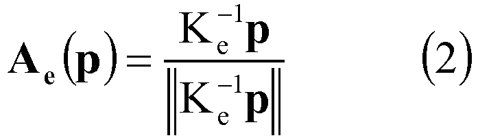
cornea 21 forms the image iat the pixel p of the eye image, the position vector at the point P can be represented as P = t1 × Ae(p). When C is the center of thecorneal sphere 21SPH, a relational expression ∥P-C∥2 = rC 2 is solved with respect to t1.

cornea 21 is determined for the light incident on the pixel p of the eye image. A vector L(p) indicating the point in the scene in the path of the light incident on the pixel p of the eye image and a normal vector N(p) on the point P of the corneal surface are obtained by the following equation.
Fig. 3 ) with respect to the corneal-surface reflection image can be constructed from the above equation. In other words, L() of the equation (5) is a mapping (transform function) to transfer the corneal-surface reflection image of the eye image Ie (seeFig. 6 ) to the environmental map of the non-rigid catadioptric imaging system. - The arithmetic section 1 (see
Fig. 4 ) acts as the mapping section to perform the arithmetic operation corresponding to the equations (2) to (5), thereby deciding mapping L() (seeFig. 3 ) to transfer the corneal-surface reflection image of the eye image Ie to the environmental map EMe. A calculation algorithm used in the arithmetic operation is stored in the image registration program (where the vector p indicates the point (pixel) in the corneal-surface reflection image of the eye image Is, and the point p in the corneal-surface reflection image of the eye image Is is transferred to the point on the environmental map EMe indicated by the vector L(p) through the mapping L()). Thearithmetic section 1 stores the decided mapping L() in thestorage device 2. - In step S4 of
Fig. 5 , thearithmetic section 1 acts as the corresponding point extractor to detect feature points (such asLP s1 and LPe1) which are not rotated and not scaled in the scene image Is (seeFig. 6A ) and the eye image Ie (seeFig. 6C ), and to calculate the local feature amount for each feature point as illustrated inFigs. 8 and9 . For example, the detection of the feature point and the calculation of the local feature amount may be performed in accordance with the SIFT. Algorithms necessary for the detection of the feature point and the calculation of the local feature amount are stored in the image registration program stored in thestorage device 2. When using the SIFT feature amount, the local feature amount calculated by thearithmetic section 1 includes four components, namely, 1. positional information (vector x), 2. orientation information (θx), 3. feature vector (vector F(x)), and 4. scale parameter (sx). Accordingly, for the local feature amount, an i-th feature point p of the eye image Ie can be expressed as follows.


arithmetic section 1 stores the position and local feature amount of the detected feature point in thestorage device 2. - The
arithmetic section 1 continues to act as the corresponding point extractor, and performs corresponding point matching (such as CP1) between the feature point (such as LPs1) in the scene image Is and the feature point (such as LPs1) in the eye image Ie based on the feature point detected by the SIFT, or the like and the calculated local feature amount.Fig. 8 illustrates a first initial corresponding point pair CP1. As illustrated inFig. 9 , thearithmetic section 1 performs the corresponding point matching plural times to obtain a plurality (M) of initial corresponding point pairs (CP1 to CPM). Thearithmetic section 1 stores information about positions of the corresponding points (LP s1 to LPsM andLP e1 to LPeM) and information about correspondence of the initial corresponding point pairs (CP1 to CPM) in thestorage device 2. - In step S5, with respect to each of the initial corresponding point pairs (CP1 to CPM) obtained in step S4, the
arithmetic section 1 derives (3 x 3 matrix) rotational mapping R for registering and aligning the scene image Is on the environmental map EMs and (the corneal-surface reflection image of) the eye image Ie on the environmental map EMe with each other, according to the following equation (6), based on the correspondence of the initial corresponding point pair (CP1, CP2, ...CPM-1, or CPM).
arithmetic section 1 derives a transform function (warping function W) for registering the pixel of the eye image Ie with the pixel of the scene image Is using the rotational mapping R. In the equation (6), the vector p and the vector q indicate points (LP s1,LP s2, ..., LPsM-1, or LEM andLP e1,LP e2, ... , LPeM-1, or LPeM) of the scene image Is and eye image Ie composing the initial corresponding point pair (CP1, CP2, ..., CPM-1, or CPM). It is assumed that an optical system included in thescene camera 11s and an image formation system included in theeye camera 11e and thecornea 21 exist in the substantially same ray environment (the assumption causes the registration between the eye image Ie and the scene image Is (derivation of the warping function W) to reduce to derivation of the rotational mapping R). - The
arithmetic section 1 derives the rotational mapping R according to the following calculation algorithm. - As can be seen from the equations (1) and (6) and
Fig. 3 , rotational mapping Ri is represented as follows. The rotational mapping Ri is expressed as shown below, in accordance with the correspondence of the initial corresponding point pair (CPi) composed of the i-th corresponding point LPsi of the scene image Is and the i-th corresponding point LPei of the eye image Ie,


arithmetic section 1 stores the warping function Wi (i = 1 to M) in thestorage device 2, correlating the warping function Wi (i = 1 to M) with the initial corresponding point pair (CP1 to CPM). - Returning to
Fig. 5 , in step S6, the arithmetic section 1 (seeFig. 4 ) acting as the corresponding point pair extractor evaluates correspondence of each of M initial corresponding point pairs, and extracts an initial corresponding point pair composed of the most highly evaluated pair, as the corresponding point pair (RANRESAC processing). More specifically, in the RANRESAC processing, thearithmetic section 1 specifies plural secondary corresponding point pairs in the first and second images according to the correspondence of one of the initial corresponding point pairs, and evaluates correspondence of each secondary corresponding point pair so as to evaluate correspondence of the one of the initial corresponding point pairs. Thearithmetic section 1 extracts the initial corresponding point pair including the most highly evaluated point pair, as the optimum initial corresponding point pair. That is, thearithmetic section 1 further obtains the secondary corresponding point pair in the eye image Ie and the scene image Is using the warping function Wi obtained in step S5 according to the initial corresponding point pair (CPi), calculates an image correlation associated with the secondary corresponding point pair, and evaluates correctness of the warping function Wi so that the optimum warping function W is determined from the plural (M) warping functions Wi. -
Fig. 10 is a flowchart illustrating the detailed processing (RANRESAC processing) of deciding the optimum initial corresponding point pair. Thearithmetic section 1 acting as the corresponding point pair extractor performs processing inFig. 10 . - In step S61, the
arithmetic section 1 acting as the corresponding point pair extractor generates a secondary corresponding point pair using the warping function Wi obtained based on the i-th corresponding point pair CPi (seeFig. 11 ). Specifically, thearithmetic section 1 detects the corneal region of the eye image Ie and randomly sets K points SLPei (seeFig. 12 ) in the corneal region. Then thearithmetic section 1 extracts a point SLPsi (seeFig. 13 ) in the scene image Is corresponding to each of the K points SLPei in the corneal region using the warping function Wi, and extracts K secondary corresponding point pairs. The secondary corresponding point pairs can also be represented as follows,
- In step S62, the
arithmetic section 1 acting as the corresponding point pair extractor evaluates similarity among the secondary corresponding point pair group (the secondary corresponding point pair group obtained according to the warping function Wi (i is a given integer (i = 1 to M))) based on similarity in correlation and direction of a local texture. Specifically, thearithmetic section 1 evaluates the similarity using the following evaluation function.
- The
arithmetic section 1 evaluates the secondary corresponding point pair group for each of the M initial corresponding point pairs using the equation (10) (step S63). - In step S64, the
arithmetic section 1 acting as the corresponding point pair extractor identifies the secondary corresponding point pair group having the most highly evaluated similarity, namely, an i'-th initial corresponding point pair (CPi') defined by the following equation (11) and its warping function Wi'.
- It is important to properly set a scale parameter for a local feature at each point composing the secondary corresponding point pair. Ideally, the scale parameter may be adjusted so as to occupy the same size (spatial volume) in the environmental map. A ratio of the scale parameter at the point (p,q) of each image is obtained according to the equation (12),

- In step S7 of
Fig. 5 , thearithmetic section 1 acting as the registration section, registers and aligns (the corneal-surface reflection image of) the eye image Ie with the scene image Is using the warping function Wi' decided in step S6 to generate data of the registered and aligned eye image.Figs. 14A illustrates (the corneal-surface reflection image of) a registered and aligned eye image IeR obtained in step S7. - In step S8 of
Fig. 5 , thearithmetic section 1 acting as the registration section finely adjusts the warping function Wi' decided in step S6 (fine registration). The data of the finely-adjusted eye image is stored in the storage device 2 (seeFig. 4 ). In this step, thearithmetic section 1 repeatedly performs the evaluation according to the equation (10) while minutely varying the position (seeFig. 7 ) of the center C of the corneal sphere, namely, the distance dLC and the rotation angle φ of the ellipse in the projection surface IP, so that an evaluation value converges. An interior point method is adopted in the convergence.Fig. 14C illustrates an image which is obtained by overlaying the pre-fine-registration image IeR on the scene image Is.Fig. 14D illustrates an image which is obtained by overlaying the post-fine-registration image IeR on the scene image Is. As can be seen fromFigs. 14C and 14D , accuracy of the registration is further improved through the fine registration processing. - In this manner, the image registration device 10 (see
Fig. 4 ) can decide the transform mapping (warping function Wi, ()) based on the only one pair of corresponding point pairs (the optimum initial corresponding point pair decided in step S6). Therefore, the registration of the eye image Ie with the scene image Is can be performed robustly. Additionally, the image registration device 10 (seeFig. 4 ) can perform the RANRESAC processing to properly decide only one pair of corresponding points. In short, the image registration device can properly decide one pair of initial corresponding points through the RANRESAC processing, and correctly perform the registration. In view of this, the image registration performed by the image registration device is robust. Even if plural initial corresponding point pairs are hardly extracted, the image registration device can correctly perform the registration as long as one pair of initial corresponding points is decided. In view of this, the image registration method is also robust. - In the embodiment, by way of example, the eye image Ie is registered and aligned with the scene image Is. Alternatively, the scene image Is may be registered and aligned with the eye image Ie. Images that can be registered and aligned by the
image registration device 10 of the embodiment is not limited to the combination of the eye image Ie and the scene image Is. In the above embodiment, theimage registration device 10 obtains data of image to be registered and aligned from the imaging device (theeye camera 11e and thescene camera 11s (seeFig. 4 )) connected to theimage registration device 10. However, theimage registration device 10 can obtain data of one or at least two images from a device (such as an image database) except for such an imaging device, and perform the registration on the obtained image(s). For example, theimage registration device 10 may obtain image data from an open database such as Google Street View through a network, and perform the registration between the obtained image and the eye image Ie (seeFig. 6 ) captured by theeye camera 11e. Alternatively, theimage registration device 10 may obtain plural pieces of image data from one or plural external devices (such as an image database) and recording media such as an optical disk and a flash memory, and perform the registration between the plural images. In such cases, theimage registration device 10 may properly prepare the mapping to transfer each obtained image to the environmental map prior to the image registration processing. The preparation method is well known to those skilled in the art. - In the
image registration device 10, the image registration program is stored in the storage device 2 (seeFig. 4 ), and the calculation algorithm necessary for the calculation of the above quantities is included in the image registration program (However, a part or whole of the calculation algorithm may be stored in thestorage device 2 independently of the image registration program). - A result of experiment conducted by the image registration device 10 (see
Fig. 4 ) of the embodiment will be described below. In the experiment, in order to stably and simultaneously photograph a corneal-surface reflection image (eye image Ie) and a scene image Is, a system was configured to include two compact board cameras (IDS UI-1241LE-C-HQ, 1/1.8'' CMOS, 1280 × 1024 pixel) and a head mount system as theeye camera 11e (seeFig. 4 ) and thescene camera 11s (seeFig. 4 ). In the system, theeye camera 11e (f = 12 mm, (H, V) = (33.3, 24.8) deg) was located away from theeyeball 20 by about 70 to 110 mm, and shot images with a pupil diameter of about 400 to 450 pixels. A gain and an exposure parameter of theeye camera 11e were adjusted under a low light intensity environment. Theeye camera 11e and thescene camera 11s were connected to the image registration device 10 (PC (Personal Computer)) and shot images at a rate of 10 fps. - The data were obtained for each of four subjects. For each subject, the data were obtained at three places in both indoor and outdoor environments. After the data of four subjects were obtained, a frame including closed lid was removed manually, and then a pupil contour was extracted in each 10 frames.
- The experiment was performed by the PC implementing the image registration method (1-point RANRESAC) of the embodiment and 2-point RANSAC and 2-point RANRESAC for the purpose of comparison.
- In the 2-point RANSAC, two pairs were randomly selected from the initial corresponding point pairs, and the warping function was estimated from the two pairs of initial corresponding points. Then, how many pairs were able to be correctly registered was counted using the remaining pairs of initial corresponding points. These operations were repeated 500 times. Then, the best solution in the obtained solutions (warping functions) was decided as the warping function.
- In the 2-point RANRESAC, the warping function was estimated similarly to the 2-point RANSAC. Then, the evaluation was performed according to the RANRESAC method. Similarly to the 2-point RANSAC, the best solution was selected from results of the 500-time repetition.
- In all the experiments, a SURF local feature implemented in a Computer Vision System Toolbox of MATLAB 2013b was used, and a PC (Intel Core i7 3.2 GHz, 16 GB RAM) was used. (σt, σo, α, sp) = (0.2, 0.2, 0.3, 0.5) was set as the parameter. The random-sampling point number (the number of pairs of corresponding points) K was set to 200 in the method (1-point RANRESAC) of the embodiment and the 2-point RANRESAC.
- Tables 1 to 7 illustrate accuracy (success rate) of the registration. Time necessary for the registration was 37.0 seconds per frame (the image registration method (1-point RANRESAC) of the embodiment), 14.47 seconds per frame (2-point RANSAC), and 180.47 seconds per frame (2-point RANRESAC).
Table 1: Experimental result under outdoor environment 1 Scene name Subject number The number of tested frames with the Method of the Embodiment 2-Point RANSAC 2-Point RANRESAC Campus 1 1 16 16 (100%) 3 (18.8%) 13 (81.25%) Campus 1 2 26 21 (80.8%) 2 (7.7%) 10 (38.5%) Campus 1 3 23 22 (94.7%) 1 (4.35%) 4 (17.39%) Campus 1 4 25 23 (92.0%) 1 (4.0%) 4 (16.0%) Table 2: Experimental result under outdoor environment 2 Scene name Subject number The number of tested frames with the Method of the Embodiment 2-Point RANSAC 2-Point RANRESAC Campus 2 1 46 41 (89.1%) 2 (4.4%) 9 (39.1%) Campus 2 2 20 16 (80.0%) 2 (10.0%) 8 (34.7%) Campus 2 3 23 21 (91.3%) 3 (13.0%) 8 (34.8%) Campus 2 4 23 17 (73.9%) 2 (8.7%) 7 (15.2%) Table 3: Experimental result under outdoor environment 3 Scene name Subject number The number of tested frames with the Method of the Embodiment 2-Point RANSAC 2-Point RANRESAC Road 1 25 25 (100.0%) 1 (4.0%) 9 (36.0%) Road 2 23 20 (87.0%) 0 (0%) 3 (13.4%) Road 3 30 26 (86.7%) 3 (10.0%) 6 (20.0%) Road 4 25 23 (92.0%) 2 (8.0%) 8 (32.0%) Table 4: Experimental result under indoor environment 1 Scene name Subject number The number of tested frames with the Method of the Embodiment 2-Point RANSAC 2-Point RANRESAC Lobby 1 1 25 18 (72.0%) 1 (4.0%) 10 (40.0%) Lobby 1 2 22 19 (86.4%) 1 (4.6%) 11 (50.6%) Lobby 1 3 25 23 (92.0%) 3 (12.0%) 10 (40.0%) Lobby 1 4 29 29 (100.0%) 2 (6.9%) 15 (51.7%) Table 5: Experimental result under indoor environment 2 Scene name Subject number The number of tested frames with the Method of the Embodiment 2-Point RANSAC 2-Point RANRESAC Lobby 2 1 24 21 (87.5%) 2 (8.3%) 13 (54.2%) Lobby 2 2 24 23 (95.8%) 1 (4.2%) 11 (45.8%) Lobby 2 3 28 27 (96.4%) 2 (7.14%) 15 (53.57%) Lobby 2 4 26 26 (100.0%) 2 (7.7%) 9 (34.6%) Table 6: Experimental result under indoor environment 3 Scene name Subject number The number of tested frames with the Method of the Embodiment 2-Point RANSAC 2-Point RANRESAC Indoor 1 25 9 (52.94%) 0 (0%) 3 (17.7%) Indoor 2 26 20 (76.9%) 2 (7.69%) 9 (34.6%) Indoor 3 26 20 (76.9%) 2 (7.69%) 5 (19.23%) Indoor 4 24 18 (75.0%) 1 (4.2%) 5 (20.8%) Table 7: Summary of experimental results Total The number of tested frames with the Method of the Embodiment 2-Point RANSAC 2-Point RANRESAC 626 538 (85.9%) 41 (6.6%) 200 (32.0%) - According to the image registration method of the present embodiment, the success rate is 85.5% (Tables 1 to 3) in the outdoor scene and it is 86.3% in the indoor scene (Tables 4 to 6), so that the success rate of the image registration method of the present embodiment is much better than that of the 2-point RANSAC and the 2-point RANRESAC. As to the success rate, the 2-point RANRESAC is not better than the 1-point RANRESAC (the present embodiment), but is better than the 2-point RANSAC which performs the same rotating matrix estimation. Therefore, it can be confirmed that the RANRESAC method is robust against noise situation.
- The image registration device and image registration method of the embodiment enable matching the corneal-surface reflection image of the eye image Ie and the scene image Is with each other. Applications using concepts of the present embodiment will be described below.
- Gazing point estimation with the image registration device of the embodiment will be described below. With the gazing point estimation, for example, an image of a scene seen by a user is extracted, and an object or a place which is seen by the user can be identified by referring to an image of the Google Street View. For example, this technology can be applied to an AR (Augmented Reality) system. In the gazing point estimation with the image registration device of the embodiment, unlike a conventional device, it is not necessary to calibrate a relative positional relationship between the eye camera and the scene camera. Additionally, it is not necessary to fix the relative positional relationship.
- First the
arithmetic section 1 acting as the viewpoint extractor detects a gazing reflection point GRP (seeFig. 15 ) of the subject by detecting the pose of the eyeball from the eye image by a known technique. As used herein, the gazing reflection point GRP means a point at which the light arriving from the visual line direction substantially aligned with the optical axis of the eyeball of the subject is reflected by the corneal surface (for example, International Patent PublicationWO2014/021169A1 is referred to for more information about the known technique). Thearithmetic section 1 derives the warping function W for registering the eye image Ie with the scene image Is. Finally, thearithmetic section 1 obtains a point GRP' (seeFig. 15 ) corresponding to the gazing reflection point GRP of the eye image Ie in the scene image Is. The point GRP' in the scene image Is corresponds to the scene (gazing point) gazed by the subject. - Thus, the image registration device of the embodiment can extract the scene (gazing point) gazed by the subject from the scene image Is. That is, the image registration device of the embodiment also acts as a gazing point extraction system.
- A display device using the image registration device acting as the gazing point extraction system will be described below. This technology can be applied to, for example, an AR (Augmented Reality) system. In the display device (AR system), unlike a conventional device, it is not necessary to calibrate the relative positional relationship between the eye camera and the scene camera. Additionally, it is not necessary to fix the relative positional relationship. The display device includes the configuration shown in
Fig. 4 similarly to the image registration device of the embodiment. Theoutput section 4 is a monitor display that displays an image. Thearithmetic section 1 causes theoutput section 4 to display the scene image Is, and causes theoutput section 4 to display a predetermined image superposed on any position in the extracted scene image Is. Therefore, the AR system can perform superposed display. - The image registration device and image registration method of the embodiment can restore the peripheral visual field of the subject in the scene image Is.
- The
arithmetic section 1 acting as the visual field estimator identifies pose (optical axis) of the eyeball using the eye image Ie, and identifies points at which light arriving from the direction having a predetermined angle (for example, 10, 20, ..., 90 degrees) with respect to the optical axis of the eyeball is reflected by the corneal surface (seeFig. 16 ). These points are distributed so as to draw a curve in the eye image Ie. Then, thearithmetic section 1 detects points corresponding to the points from the scene image Is using the warping function W decided in the embodiment. The detected points form a region of the peripheral visual field of the subject (a region expanding with a predetermined angle around the gazing point). - Thus, the image registration device of the embodiment can extract the region of the peripheral visual field of the subject from the scene image Is. The image registration device can estimate the region of the peripheral visual field of the subject in the scene image Is. That is, the image registration device also acts as the peripheral visual field estimation system.
- In an existing iris recognition technique, the eye image is obtained using infrared light in order to suppress the specular reflection on the corneal surface. On the other hand, with the image registration device of the embodiment, the specular reflection (corneal-surface reflection image) included in the eye image can be removed using the scene image.
- The
arithmetic section 1 of the image registration device of the embodiment derives the warping function W between the eye image Ie (seeFig. 17 ) and the scene image Is (seeFig. 17 ). Thearithmetic section 1 registers and aligns the scene image Is with the eye image Ie using the warping function W. Thearithmetic section 1 acting as an iris image generator subtracts the registered and aligned scene image Is from a portion of the eye image Ie corresponding to the registered and aligned scene image Is, thereby removing the corneal-surface reflection image of the eye image Ie to generate the iris image. An image Iit inFig. 17 is an eye image in which the corneal specular reflection is effectively removed, namely, an iris image. Thus, according to the image registration device of the embodiment, the corneal specular reflection included in the eye image Ie can effectively be removed, so that the iris image Iit without noise can be obtained. Therefore, it is not necessary to use the infrared light in the lighting in order to suppress the specular reflection in the corneal surface. Then, thearithmetic section 1 acting as the recognizer performs iris recognition processing on the iris image using a known method. - In this way, according to the image registration device of the embodiment, even if the eye image is obtained using lighting of visible light region in addition to an infrared lighting, the corneal specular reflection can effectively be removed, thereby obtaining a high accurate iris image. Using the iris image obtained in such a manner can improve accuracy of iris recognition. That is, the image registration device of the embodiment acts as the iris recognition system.
- In view of the above, the embodiment also discloses the following systems and methods.
- (1) A gazing point extraction system including:
- an obtaining section configured to obtain a first image including an image of an eyeball of a subject and a second image including an image of an object in a visual line direction of the subject;
- a mapping section configured to decide a first mapping for transforming the first image to an environmental map, and a second mapping for transforming the second image to an environmental map;
- a corresponding point pair extractor configured to extract a pair of corresponding points by detecting one point in the first image and one point in the second image which corresponds to the one point in the first image;
- a rotational mapping deriver configured to derive a rotational mapping for registering an image of the first image in the environmental map and an image of the second image in the environmental map with each other, based on positions and local feature amounts of the one point in the first image and the one point in the second image, the one point in the first image and the one point in the second image composing the pair of corresponding points; and
- a viewpoint extractor configured to detect a gazing reflection point on the first image by detecting a pose of the eyeball from the first image, and to obtain, as a point gazed by the subject, a point corresponding to the gazing reflection point in the second image based on the first mapping, the rotational mapping, and the second mapping.
- (2) A display system (AR system) including the gazing point extraction system of (1).
- (3) A peripheral visual field estimation system including:
- an obtaining section configured to obtain a first image including an image of an eyeball of a subject and a second image including an image of an object in a visual line direction of the subject;
- a mapping section configured to decide a first mapping for transforming the first image to an environmental map, and a second mapping for transforming the second image to an environmental map;
- a corresponding point pair extractor configured to extract a pair of corresponding points by detecting one point in the first image and one point in the second image which corresponds to the one point in the first image;
- a rotational mapping deriver configured to derive a rotational mapping for registering an image of the first image in the environmental map and an image of the second image in the environmental map with each other, based on positions and local feature amounts of the one point in the first image and the one point in the second image, the one point in the first image and the one point in the second image composing the pair of corresponding points; and
- a visual field estimator configured to identify an optical axis of the eyeball from the first image, identify reflection points at which lights arriving from directions having predetermined angles with respect to the optical axis is reflected by a corneal surface, and detect reflection points identified from the second image, as a group of points composing a region of a peripheral visual field of the subject, based on the first mapping, the rotational mapping, and the second mapping.
- (4) An iris recognition system including:
- an obtaining section configured to obtain data of a first image including an image of an eyeball of a subject and a second image including an image of an object in a visual line direction of the subject;
- a storage device configured to store the data of the first image and the data of the second image;
- a mapping section configured to decide a first mapping for transforming the first image to an environmental map, and a second mapping for transforming the second image to an environmental map;
- a corresponding point pair extractor configured to extract a pair of corresponding points by detecting one point in the first image and one point in the second image which corresponds to the one point in the first image;
- a rotational mapping deriver configured to derive a rotational mapping for registering an image of the first image in the environmental map and an image of the second image in the environmental map with each other, based on positions and local feature amounts of the one point in the first image and the one point in the second image which compose the pair of corresponding points; and
- a registration section configured to register the data of the first image stored in the storage device with the data of the second image stored in the storage device in order to generate data of the first image registered with the second image, based on the first mapping, the rotational mapping, and the second mapping;
- an iris image generator configured to generate an iris image by subtracting the registered first image from the second image; and
- a recognizer configured to perform iris recognition with the iris image.
- (5) A gazing point extraction method including the steps of:
- obtaining a first image including an image of an eyeball of a subject and a second image including an image of an object in a visual line direction of the subject;
- deciding, by an arithmetic section, a first mapping for transforming the first image to an environmental map, and a second mapping for transforming the second image to an environmental map;
- extracting, by the arithmetic section, a pair of corresponding points by detecting one point in the first image and one point in the second image which corresponds to the one point in the first image;
- deriving, by the arithmetic section, a rotational mapping for registering an image of the first image in the environmental map and an image of the second image in the environmental map with each other, based on positions and local feature amounts of the one point in the first image and the one point in the second image, the one point in the first image and the one point in the second image composing the pair of corresponding points; and
- detecting, by the arithmetic section, a gazing reflection point on the first image by detecting a pose of the eyeball from the first image, and
- obtaining, by the arithmetic section, as a point gazed by the subject, a point corresponding to the gazing reflection point in the second image, based on the first mapping, the rotational mapping, and the second mapping.
- (6) A peripheral visual field estimation method including the steps of:
- obtaining, by an arithmetic section, a first image including an image of an eyeball of a subject and a second image including an image of an object in a visual line direction of the subject;
- deciding, by the arithmetic section, a first mapping for transforming the first image to an environmental map, and a second mapping for transforming the second image to an environmental map;
- extracting, by the arithmetic section, a pair of corresponding points by detecting one point in the first image and one point in the second image which corresponds to the one point in the first image;
- deriving, by the arithmetic section, a rotational mapping for registering an image of the first image in the environmental map and an image of the second image in the environmental map with each other, based on positions and local feature amounts of the one point in the first image and the one point in the second image, the one point in the first image and the one point in the second image composing the pair of corresponding points;
- identifying, by the arithmetic section, an optical axis of the eyeball from the first image;
- identifying, by the arithmetic section, reflection points at which lights arriving from directions having predetermined angles with respect to the optical axis are reflected by a corneal surface; and
- detecting, by the arithmetic section, reflection points identified from the second image, as a group of points composing a region of a peripheral visual field of the subject, based on the first mapping, the rotational mapping, and the second mapping.
- (7) An iris recognition method including the steps of:
- obtaining data of a first image including an image of an eyeball of a subject and a second image including an image of an object in a visual line direction of the subject;
- storing the data of the first image and the data of the second image;
- deciding, by the arithmetic section, a first mapping for transforming the first image to an environmental map, and a second mapping for transforming the second image to an environmental map;
- extracting, by the arithmetic section, a pair of corresponding points by detecting one point in the first image and one point in the second image which corresponds to the one point in the first image;
- deriving, by the arithmetic section, a rotational mapping for registering an image of the first image in the environmental map and an image of the second image in the environmental map with each other, based on positions and local feature amounts of the one point in the first image and the one point in the second image which compose the pair of corresponding points; and
- registering, by the arithmetic section, the data of the first image stored in the storage device with the data of the second image stored in the storage device in order to generate data of the first image registered with the second image, based on the first mapping, the rotational mapping, and the second mapping;
- generating, by the arithmetic section, an iris image by subtracting the registered first image from the second image; and
- performing, by the arithmetic section, iris recognition with the iris image.
- The present invention is described above in association with the specific embodiments. However, it is further understood by those skilled in the art that many changes, modifications, substitutions, deletions, and applications can be made in the present invention. Therefore, the present invention is not limited to a specific disclosure, but limited only to the attached claims.
Claims (15)
- An image registration device comprising:an obtaining section configured to obtain data of a first image and data of a second image;a storage device configured to store the data of the first image and the data of the second image;a mapping section configured to decide a first mapping for transforming the first image to an environmental map, and a second mapping for transforming the second image to an environmental map;a corresponding point pair extractor configured to extract a pair of corresponding points by detecting one point in the first image and one point in the second image which corresponds to the one point in the first image;a rotational mapping deriver configured to derive a rotational mapping for registering an image of the first image in the environmental map and an image of the second image in the environmental map with each other, based on positions and local feature amounts of the one point in the first image and the one point in the second image which compose the pair of corresponding points; anda registration section configured to register the data of the first image stored in the storage device with the data of the second image stored in the storage device in order to generate data of the first image registered with the second image, based on the first mapping, the rotational mapping, and the second mapping.
- The image registration device according to claim 1, wherein the local feature amount includes orientation information.
- The image registration device according to claim 1 or 2, wherein the corresponding point pair extractor detects a plurality of candidate pairs of corresponding points, as a candidate of the pair of corresponding points including the point of the first image and the point of the second image,, evaluates a correspondence between corresponding points for each candidate pair, and extracts a candidate pair of the corresponding points which are most highly evaluated, as the pair of corresponding points.
- The image registration device according to claim 3, wherein the corresponding point pair extractor evaluates the correspondence between the corresponding points for the candidate pair, by evaluating correspondences of plural secondary pairs of corresponding points composed of pairs of corresponding points extracted from the first image and the second image according to the correspondence between the point of the first image and the point of the second image, the point of the first image and the point of the second image composing the candidate pair of corresponding points.
- The image registration device according to claim 1, wherein the first image including an image of an eyeball of a subject, and the second image including an image of an object in a visual line direction of the subject.
- An image registration system comprising:a first camera configured to photograph a first image;a second camera configured to photograph a second image; andthe image registration device according to any one of claims 1 to 5 configured to perform image registration for the first image and the second image.
- An image registration method comprising:an obtaining step of obtaining data of a first image and data of a second image;a storing step of storing the data of the first image and the data of the second image in a storage device;a deciding step of deciding, by an arithmetic section, a first mapping for transforming the first image to an environmental map, and a second mapping for transforming the second image to an environmental map;an extracting step of extracting, by the arithmetic section, a pair of corresponding points, by detecting one point in the first image and one point in the second image which corresponds to the one point in the first image;a deriving step of deriving, by the arithmetic section, a rotational mapping for registering an image of the first image in the environmental map and an image of the second image in the environmental map with each other, based on positions and local feature amounts of the one point in the first image and the one point in the second image, the one point in the first image and the one point in the second image composing the pair of corresponding points; anda generating step of generating, by the arithmetic section, data of the first image registered with the second image by registering the data of the first image stored in the storage device with the data of the second image stored in the storage device based on the first mapping, the rotational mapping, and the second mapping.
- An image registration program that is executable by a computer, the image registration program causing the computer to perform:an obtaining step of obtaining data of a first image and data of a second image;a storing step of storing the data of the first image and the data of the second image in a storage device;a deciding step of deciding, by an arithmetic section, a first mapping for transforming the first image to an environmental map, and a second mapping for transforming the second image to an environmental map;an extracting step of extracting, by the arithmetic section, a pair of corresponding points, by detecting one point in the first image and one point in the second image which corresponds to the one point in the first image;a deriving step of deriving, by the arithmetic section, a rotational mapping for registering an image of the first image in the environmental map and an image of the second image in the environmental map with each other, based on positions and local feature amounts of the one point in the first image and the one point in the second image, the one point in the first image and the one point in the second image composing the pair of corresponding points; anda generating step of generating, by the arithmetic section, data of the first image registered with the second image by registering the data of the first image stored in the storage device with the data of the second image stored in the storage device based on the first mapping, the rotational mapping, and the second mapping.
- A gazing point extraction system comprising:an obtaining section configured to obtain a first image including an image of an eyeball of a subject and a second image including an image of an object in a visual line direction of the subject;a mapping section configured to decide a first mapping for transforming the first image to an environmental map, and a second mapping for transforming the second image to an environmental map;a corresponding point pair extractor configured to extract a pair of corresponding points by detecting one point in the first image and one point in the second image which corresponds to the one point in the first image;a rotational mapping deriver configured to derive a rotational mapping for registering an image of the first image in the environmental map and an image of the second image in the environmental map with each other, based on positions and local feature amounts of the one point in the first image and the one point in the second image, the one point in the first image and the one point in the second image composing the pair of corresponding points; anda viewpoint extractor configured to detect a gazing reflection point on the first image by detecting a pose of the eyeball from the first image, and to obtain, as a point gazed by the subject, a point corresponding to the gazing reflection point in the second image based on the first mapping, the rotational mapping, and the second mapping.
- A display system comprising the gazing point extraction system according to claim 9.
- A peripheral visual field estimation system comprising:an obtaining section configured to obtain a first image including an image of an eyeball of a subject and a second image including an image of an object in a visual line direction of the subject;a mapping section configured to decide a first mapping for transforming the first image to an environmental map, and a second mapping for transforming the second image to an environmental map;a corresponding point pair extractor configured to extract a pair of corresponding points by detecting one point in the first image and one point in the second image which corresponds to the one point in the first image;a rotational mapping deriver configured to derive a rotational mapping for registering an image of the first image in the environmental map and an image of the second image in the environmental map with each other, based on positions and local feature amounts of the one point in the first image and the one point in the second image, the one point in the first image and the one point in the second image composing the pair of corresponding points; anda visual field estimator configured to identify an optical axis of the eyeball from the first image, identify reflection points at which lights arriving from directions having predetermined angles with respect to the optical axis is reflected by a corneal surface, and detect reflection points identified from the second image, as a group of points composing a region of a peripheral visual field of the subject, based on the first mapping, the rotational mapping, and the second mapping.
- An iris recognition system comprising:an obtaining section configured to obtain data of a first image including an image of an eyeball of a subject and a second image including an image of an object in a visual line direction of the subject;a storage device configured to store the data of the first image and the data of the second image;a mapping section configured to decide a first mapping for transforming the first image to an environmental map, and a second mapping for transforming the second image to an environmental map;a corresponding point pair extractor configured to extract a pair of corresponding points by detecting one point in the first image and one point in the second image which corresponds to the one point in the first image;a rotational mapping deriver configured to derive a rotational mapping for registering an image of the first image in the environmental map and an image of the second image in the environmental map with each other, based on positions and local feature amounts of the one point in the first image and the one point in the second image which compose the pair of corresponding points; anda registration section configured to register the data of the first image stored in the storage device with the data of the second image stored in the storage device in order to generate data of the first image registered with the second image, based on the first mapping, the rotational mapping, and the second mapping;an iris image generator configured to generate an iris image by subtracting the registered first image from the second image; anda recognizer configured to perform iris recognition with the iris image.
- A gazing point extraction method comprising the steps of:obtaining a first image including an image of an eyeball of a subject and a second image including an image of an object in a visual line direction of the subject;deciding, by an arithmetic section, a first mapping for transforming the first image to an environmental map, and a second mapping for transforming the second image to an environmental map;extracting, by the arithmetic section, a pair of corresponding points by detecting one point in the first image and one point in the second image which corresponds to the one point in the first image;deriving, by the arithmetic section, a rotational mapping for registering an image of the first image in the environmental map and an image of the second image in the environmental map with each other, based on positions and local feature amounts of the one point in the first image and the one point in the second image, the one point in the first image and the one point in the second image composing the pair of corresponding points; anddetecting, by the arithmetic section, a gazing reflection point on the first image by detecting a pose of the eyeball from the first image, andobtaining, by the arithmetic section, as a point gazed by the subject, a point corresponding to the gazing reflection point in the second image, based on the first mapping, the rotational mapping, and the second mapping.
- A peripheral visual field estimation method comprising the steps of:obtaining, by an arithmetic section, a first image including an image of an eyeball of a subject and a second image including an image of an object in a visual line direction of the subject;deciding, by the arithmetic section, a first mapping for transforming the first image to an environmental map, and a second mapping for transforming the second image to an environmental map;extracting, by the arithmetic section, a pair of corresponding points by detecting one point in the first image and one point in the second image which corresponds to the one point in the first image;deriving, by the arithmetic section, a rotational mapping for registering an image of the first image in the environmental map and an image of the second image in the environmental map with each other, based on positions and local feature amounts of the one point in the first image and the one point in the second image, the one point in the first image and the one point in the second image composing the pair of corresponding points;identifying, by the arithmetic section, an optical axis of the eyeball from the first image;identifying, by the arithmetic section, reflection points at which lights arriving from directions having predetermined angles with respect to the optical axis are reflected by a corneal surface; anddetecting, by the arithmetic section, reflection points identified from the second image, as a group of points composing a region of a peripheral visual field of the subject, based on the first mapping, the rotational mapping, and the second mapping.
- An iris recognition method comprising the steps of:obtaining data of a first image including an image of an eyeball of a subject and a second image including an image of an object in a visual line direction of the subject;storing the data of the first image and the data of the second image;deciding, by the arithmetic section, a first mapping for transforming the first image to an environmental map, and a second mapping for transforming the second image to an environmental map;extracting, by the arithmetic section, a pair of corresponding points by detecting one point in the first image and one point in the second image which corresponds to the one point in the first image;deriving, by the arithmetic section, a rotational mapping for registering an image of the first image in the environmental map and an image of the second image in the environmental map with each other, based on positions and local feature amounts of the one point in the first image and the one point in the second image which compose the pair of corresponding points; andregistering, by the arithmetic section, the data of the first image stored in the storage device with the data of the second image stored in the storage device in order to generate data of the first image registered with the second image, based on the first mapping, the rotational mapping, and the second mapping;generating, by the arithmetic section, an iris image by subtracting the registered first image from the second image; andperforming, by the arithmetic section, iris recognition with the iris image.
Applications Claiming Priority (2)
| Application Number | Priority Date | Filing Date | Title |
|---|---|---|---|
| JP2014150848 | 2014-07-24 | ||
| PCT/JP2015/071027 WO2016013634A1 (en) | 2014-07-24 | 2015-07-23 | Image registration device, image registration method, and image registration program |
Publications (2)
| Publication Number | Publication Date |
|---|---|
| EP3188129A1 true EP3188129A1 (en) | 2017-07-05 |
| EP3188129A4 EP3188129A4 (en) | 2018-03-07 |
Family
ID=55163158
Family Applications (1)
| Application Number | Title | Priority Date | Filing Date |
|---|---|---|---|
| EP15825115.7A Withdrawn EP3188129A4 (en) | 2014-07-24 | 2015-07-23 | Image registration device, image registration method, and image registration program |
Country Status (6)
| Country | Link |
|---|---|
| US (1) | US10628948B2 (en) |
| EP (1) | EP3188129A4 (en) |
| JP (1) | JP6371849B2 (en) |
| KR (1) | KR101909006B1 (en) |
| CN (1) | CN106575439B (en) |
| WO (1) | WO2016013634A1 (en) |
Cited By (1)
| Publication number | Priority date | Publication date | Assignee | Title |
|---|---|---|---|---|
| CN114529593A (en) * | 2022-01-12 | 2022-05-24 | 西安电子科技大学 | Infrared and visible light image registration method, system, equipment and image processing terminal |
Families Citing this family (14)
| Publication number | Priority date | Publication date | Assignee | Title |
|---|---|---|---|---|
| KR102520108B1 (en) * | 2016-06-07 | 2023-04-11 | 삼성디스플레이 주식회사 | Transparent display apparatus, driving method thereof, and apparatus for acquirung image |
| JP6717377B2 (en) * | 2016-07-04 | 2020-07-01 | ソニー株式会社 | Information processing device, information processing method, and program |
| KR102589853B1 (en) * | 2016-10-27 | 2023-10-16 | 삼성전자주식회사 | Image display apparatus and method for displaying image |
| WO2018198840A1 (en) * | 2017-04-28 | 2018-11-01 | 株式会社ニコン | Ophthalmological device |
| CN107230066B (en) * | 2017-06-01 | 2020-11-03 | 珠海市魅族科技有限公司 | A payment method and device, computer device, and readable storage medium |
| WO2019030375A2 (en) * | 2017-08-11 | 2019-02-14 | Carl Zeiss Meditec, Inc. | Systems and methods for improved ophthalmic imaging |
| RU2749643C1 (en) | 2017-12-19 | 2021-06-16 | Телефонактиеболагет Лм Эрикссон (Пабл) | Head-mounted display device and method performed by them |
| US11335079B2 (en) * | 2018-03-05 | 2022-05-17 | Intel Corporation | Method and system of reflection suppression for image processing |
| JP6840697B2 (en) * | 2018-03-23 | 2021-03-10 | 株式会社豊田中央研究所 | Line-of-sight direction estimation device, line-of-sight direction estimation method, and line-of-sight direction estimation program |
| JP7173836B2 (en) * | 2018-11-05 | 2022-11-16 | 京セラ株式会社 | Controller, position determination device, position determination system, display system, program, and recording medium |
| CN110220675B (en) * | 2019-06-11 | 2021-09-28 | 深圳创维-Rgb电子有限公司 | Display performance test system, method, terminal and storage medium |
| US11826101B2 (en) | 2019-08-06 | 2023-11-28 | Alcon Inc. | Scene camera systems and methods for vitreoretinal surgery |
| CN111815688B (en) * | 2020-06-24 | 2022-10-21 | 杭州宏华数码科技股份有限公司 | Accurate registration method of long line image |
| US12646148B2 (en) * | 2021-04-21 | 2026-06-02 | Bayer Aktiengesellschaft | Implicit registration for improving synthesized full-contrast image prediction tool |
Family Cites Families (18)
| Publication number | Priority date | Publication date | Assignee | Title |
|---|---|---|---|---|
| JP3817302B2 (en) * | 1996-05-28 | 2006-09-06 | キヤノン株式会社 | Image generation device |
| US6389179B1 (en) * | 1996-05-28 | 2002-05-14 | Canon Kabushiki Kaisha | Image combining apparatus using a combining algorithm selected based on an image sensing condition corresponding to each stored image |
| JP2001108933A (en) | 1999-08-03 | 2001-04-20 | Sony Corp | Head mounted display device |
| US20050063608A1 (en) * | 2003-09-24 | 2005-03-24 | Ian Clarke | System and method for creating a panorama image from a plurality of source images |
| JP4595750B2 (en) * | 2005-08-29 | 2010-12-08 | ソニー株式会社 | Image processing apparatus and method, and program |
| US8077914B1 (en) * | 2006-08-07 | 2011-12-13 | Arkady Kaplan | Optical tracking apparatus using six degrees of freedom |
| JP5217585B2 (en) | 2008-04-09 | 2013-06-19 | セイコーエプソン株式会社 | Head-mounted image display device |
| JP2010056661A (en) | 2008-08-26 | 2010-03-11 | Olympus Corp | Head mounting type video acquiring and displaying device |
| JP5329882B2 (en) | 2008-09-17 | 2013-10-30 | パイオニア株式会社 | Display device |
| JP5295714B2 (en) | 2008-10-27 | 2013-09-18 | 株式会社ソニー・コンピュータエンタテインメント | Display device, image processing method, and computer program |
| JP5612371B2 (en) * | 2010-06-11 | 2014-10-22 | 富士フイルム株式会社 | Image alignment apparatus and method, and program |
| FR2970576B1 (en) * | 2011-01-19 | 2013-02-08 | Matchic Labs | METHOD FOR DETERMINING THE DIRECTION OF THE LOOK AND DEVICE FOR IMPLEMENTING IT |
| JP5733565B2 (en) * | 2011-03-18 | 2015-06-10 | ソニー株式会社 | Image processing apparatus and method, and program |
| CN102324043B (en) * | 2011-09-07 | 2013-12-18 | 北京邮电大学 | Image matching method based on DCT (Discrete Cosine Transformation) through feature description operator and optimization space quantization |
| US9262680B2 (en) | 2012-07-31 | 2016-02-16 | Japan Science And Technology Agency | Point-of-gaze detection device, point-of-gaze detecting method, personal parameter calculating device, personal parameter calculating method, program, and computer-readable storage medium |
| CN103024350B (en) * | 2012-11-13 | 2015-07-29 | 清华大学 | A kind of principal and subordinate's tracking of binocular PTZ vision system and the system of application the method |
| JP5533988B2 (en) * | 2012-11-30 | 2014-06-25 | 株式会社デンソーアイティーラボラトリ | Image processing system |
| US10007336B2 (en) * | 2013-09-10 | 2018-06-26 | The Board Of Regents Of The University Of Texas System | Apparatus, system, and method for mobile, low-cost headset for 3D point of gaze estimation |
-
2015
- 2015-07-23 EP EP15825115.7A patent/EP3188129A4/en not_active Withdrawn
- 2015-07-23 WO PCT/JP2015/071027 patent/WO2016013634A1/en not_active Ceased
- 2015-07-23 KR KR1020177000056A patent/KR101909006B1/en not_active Expired - Fee Related
- 2015-07-23 CN CN201580039748.5A patent/CN106575439B/en not_active Expired - Fee Related
- 2015-07-23 JP JP2016535977A patent/JP6371849B2/en active Active
-
2017
- 2017-01-24 US US15/413,629 patent/US10628948B2/en active Active
Cited By (1)
| Publication number | Priority date | Publication date | Assignee | Title |
|---|---|---|---|---|
| CN114529593A (en) * | 2022-01-12 | 2022-05-24 | 西安电子科技大学 | Infrared and visible light image registration method, system, equipment and image processing terminal |
Also Published As
| Publication number | Publication date |
|---|---|
| US20170169578A1 (en) | 2017-06-15 |
| KR101909006B1 (en) | 2018-10-17 |
| CN106575439B (en) | 2019-05-31 |
| JP6371849B2 (en) | 2018-08-08 |
| CN106575439A (en) | 2017-04-19 |
| KR20170020839A (en) | 2017-02-24 |
| US10628948B2 (en) | 2020-04-21 |
| EP3188129A4 (en) | 2018-03-07 |
| JPWO2016013634A1 (en) | 2017-06-01 |
| WO2016013634A1 (en) | 2016-01-28 |
Similar Documents
| Publication | Publication Date | Title |
|---|---|---|
| US10628948B2 (en) | Image registration device, image registration method, and image registration program | |
| US9881204B2 (en) | Method for determining authenticity of a three-dimensional object | |
| US9235928B2 (en) | 3D body modeling, from a single or multiple 3D cameras, in the presence of motion | |
| US11232586B2 (en) | Line-of-sight estimation device, line-of-sight estimation method, and program recording medium | |
| US11321960B2 (en) | Deep learning-based three-dimensional facial reconstruction system | |
| EP3506149B1 (en) | Method, system and computer program product for point of gaze estimation | |
| CN104809424B (en) | Method for realizing sight tracking based on iris characteristics | |
| CN113192132B (en) | Eye catch method and device, storage medium and terminal | |
| JP5001930B2 (en) | Motion recognition apparatus and method | |
| CN113920563B (en) | Online exam cheating identification method, device, computer equipment and storage medium | |
| JP6191943B2 (en) | Gaze direction estimation device, gaze direction estimation device, and gaze direction estimation program | |
| CN110781712B (en) | Human head space positioning method based on human face detection and recognition | |
| CN111898571A (en) | Action recognition system and method | |
| WO2019003973A1 (en) | Facial authentication device, facial authentication method, and program recording medium | |
| EP3154407A1 (en) | A gaze estimation method and apparatus | |
| CN118314197A (en) | Human eye positioning method, device, equipment and medium | |
| JP2017123087A (en) | Program, apparatus and method for calculating normal vector of planar object reflected in continuous captured images | |
| Taiana et al. | Tracking objects with generic calibrated sensors: An algorithm based on color and 3D shape features | |
| JP2018149234A (en) | Fixation point estimation system, fixation point estimation method, and fixation point estimation program | |
| JP6302427B2 (en) | Image data processing method, image data processing apparatus, and image data processing program | |
| CN119992634A (en) | Human-computer interaction eye tracking method | |
| Prasad et al. | A robust head pose estimation system for uncalibrated monocular videos | |
| JP5688514B2 (en) | Gaze measurement system, method and program | |
| Cheung et al. | Pose-tolerant non-frontal face recognition using EBGM | |
| CN113689541B (en) | Two-person three-dimensional human body shape optimization reconstruction method in interactive scene |
Legal Events
| Date | Code | Title | Description |
|---|---|---|---|
| STAA | Information on the status of an ep patent application or granted ep patent |
Free format text: STATUS: THE INTERNATIONAL PUBLICATION HAS BEEN MADE |
|
| PUAI | Public reference made under article 153(3) epc to a published international application that has entered the european phase |
Free format text: ORIGINAL CODE: 0009012 |
|
| STAA | Information on the status of an ep patent application or granted ep patent |
Free format text: STATUS: REQUEST FOR EXAMINATION WAS MADE |
|
| 17P | Request for examination filed |
Effective date: 20170220 |
|
| AK | Designated contracting states |
Kind code of ref document: A1 Designated state(s): AL AT BE BG CH CY CZ DE DK EE ES FI FR GB GR HR HU IE IS IT LI LT LU LV MC MK MT NL NO PL PT RO RS SE SI SK SM TR |
|
| AX | Request for extension of the european patent |
Extension state: BA ME |
|
| DAV | Request for validation of the european patent (deleted) | ||
| DAX | Request for extension of the european patent (deleted) | ||
| A4 | Supplementary search report drawn up and despatched |
Effective date: 20180205 |
|
| RIC1 | Information provided on ipc code assigned before grant |
Ipc: G06T 7/60 20170101AFI20180130BHEP Ipc: G06T 5/50 20060101ALI20180130BHEP Ipc: G06T 7/00 20170101ALI20180130BHEP Ipc: A61B 3/113 20060101ALI20180130BHEP Ipc: H04N 5/225 20060101ALI20180130BHEP |
|
| STAA | Information on the status of an ep patent application or granted ep patent |
Free format text: STATUS: EXAMINATION IS IN PROGRESS |
|
| 17Q | First examination report despatched |
Effective date: 20200430 |
|
| STAA | Information on the status of an ep patent application or granted ep patent |
Free format text: STATUS: THE APPLICATION HAS BEEN WITHDRAWN |
|
| 18W | Application withdrawn |
Effective date: 20200907 |