EP3187832A1 - Magnetic position detection device - Google Patents
Magnetic position detection device Download PDFInfo
- Publication number
- EP3187832A1 EP3187832A1 EP15835725.1A EP15835725A EP3187832A1 EP 3187832 A1 EP3187832 A1 EP 3187832A1 EP 15835725 A EP15835725 A EP 15835725A EP 3187832 A1 EP3187832 A1 EP 3187832A1
- Authority
- EP
- European Patent Office
- Prior art keywords
- magnetic
- magnet
- detection element
- bias
- bias magnet
- Prior art date
- Legal status (The legal status is an assumption and is not a legal conclusion. Google has not performed a legal analysis and makes no representation as to the accuracy of the status listed.)
- Granted
Links
Images


Classifications
-
- G—PHYSICS
- G01—MEASURING; TESTING
- G01D—MEASURING NOT SPECIALLY ADAPTED FOR A SPECIFIC VARIABLE; ARRANGEMENTS FOR MEASURING TWO OR MORE VARIABLES NOT COVERED IN A SINGLE OTHER SUBCLASS; TARIFF METERING APPARATUS; MEASURING OR TESTING NOT OTHERWISE PROVIDED FOR
- G01D5/00—Mechanical means for transferring the output of a sensing member; Means for converting the output of a sensing member to another variable where the form or nature of the sensing member does not constrain the means for converting; Transducers not specially adapted for a specific variable
- G01D5/12—Mechanical means for transferring the output of a sensing member; Means for converting the output of a sensing member to another variable where the form or nature of the sensing member does not constrain the means for converting; Transducers not specially adapted for a specific variable using electric or magnetic means
- G01D5/14—Mechanical means for transferring the output of a sensing member; Means for converting the output of a sensing member to another variable where the form or nature of the sensing member does not constrain the means for converting; Transducers not specially adapted for a specific variable using electric or magnetic means influencing the magnitude of a current or voltage
- G01D5/142—Mechanical means for transferring the output of a sensing member; Means for converting the output of a sensing member to another variable where the form or nature of the sensing member does not constrain the means for converting; Transducers not specially adapted for a specific variable using electric or magnetic means influencing the magnitude of a current or voltage using Hall-effect devices
- G01D5/145—Mechanical means for transferring the output of a sensing member; Means for converting the output of a sensing member to another variable where the form or nature of the sensing member does not constrain the means for converting; Transducers not specially adapted for a specific variable using electric or magnetic means influencing the magnitude of a current or voltage using Hall-effect devices influenced by the relative movement between the Hall device and magnetic fields
Definitions
- the present invention relates to a magnetic position detection device using a magnetic detection element and utilized for a position sensor and a stroke sensor, for example.
- spin-valve magnetic resistance elements are arranged at the same position with respect to a magnetic pole arrangement direction of magnetic members having N-poles and S-poles alternatively magnetized.
- object magnets Although conventional techniques require multiple magnets to be detected (object magnets), multiple object magnets cannot be arranged in some cases due to restriction on space. Using only one object magnetic leads to a problem of a narrow detectable stroke range. Additionally, objects to be detected are limited to magnets.
- the present invention was conceived in view of the situations and it is therefore a first object of the present invention to provide a magnetic position detection device capable of preferable position detection even when only one object magnet is used.
- a second object of the present invention is to provide a magnetic position detection device capable of preferable position detection even when an object to be detected is a soft magnetic body.
- a first aspect of the present invention is a magnetic position detection device.
- the magnetic position detection device comprises:
- the same poles may face each other between the object magnet and the bias magnet.
- a magnetic pole surface of the bias magnet facing toward the object magnet and a magnetic pole surface of the object magnet facing toward the bias magnet may be substantially parallel to, and the same in polarity as, each other and may be substantially parallel to a relative movement direction of the object magnet.
- a magnetic pole surface of the bias magnet facing toward the object magnet and a magnetic pole surface of the object magnet facing toward the bias magnet may be substantially parallel to, and different in polarity from, each other and may be substantially parallel to a relative movement direction of the object magnet.
- a magnetic pole surface of the bias magnet and a magnetic pole surface of the object magnet may be substantially parallel to each other and may be substantially perpendicular to a relative movement direction of the object magnet.
- a magnetic pole surface of the bias magnet and a magnetic pole surface of the object magnet may be substantially perpendicular to each other.
- a second aspect of the present invention is a magnetic position detection device.
- the magnetic position detection device comprises:
- a magnetic pole surface of the object magnet may have a length related to a direction of the relative movement longer than that of a magnetic pole surface of the bias magnet.
- a position of the object magnet relative to the bias magnet may be uniquely identifiable.
- the magnetic detection element may be located at a position coming closer to the object magnet than the bias magnet when the bias magnet is right in front of the object magnet.
- the only one object magnet may be included.
- a third embodiment of the present invention is a magnetic position detection device.
- the magnetic position detection device comprises:
- the first and second aspects of the present invention can provide the magnetic position detection device capable of favorable position detection even when only one object magnet is used.
- the third aspect of the present invention can provide the magnetic position detection device capable of favorable position detection even when an object to be detected is a soft magnetic body.
- Fig. 1 is a schematic configuration diagram of a magnetic position detection device according to a first embodiment of the present invention.
- X-direction, Y-direction, and Z-direction are defined as three orthogonal directions.
- Fig. 1 also shows a portion of magnetic lines generated by a bias magnet 1 and an object magnet 3.
- the magnetic position detection device of this embodiment includes the bias magnet 1, a magnetic detection element 2, the object magnet 3, and a mobile object 4.
- the bias magnet 1 and the object magnet 3 are preferably rare-earth magnets such as neodymium magnets and are formed into a columnar shape or a prismatic shape, for example, and arranged such that different poles face each other.
- the S-pole surface of the bias magnet 1 and the N-pole surface of the object magnet 3 face each other.
- the facing magnetic pole surfaces of the bias magnet 1 and the object magnet 3 are both parallel to the XZ plane.
- the non-facing magnetic pole surfaces of the bias magnet 1 and the object magnet 3 are also both parallel to the XZ plane.
- the facing magnetic pole surface of the object magnet 3 has a length related to a relative movement direction (X-direction, or X- and Y-directions) longer than that of the facing magnetic pole surface of the bias magnet 1.
- the object magnet 3 has a more flattened shape than the bias magnet 1.
- the magnetic detection element 2 is disposed in front of the S-pole surface of the bias magnet 1 (the facing magnetic pole surface toward the object magnet 3).
- the magnetic detection element 2 is fixedly disposed relative to the bias magnet 1 so as to fix a relative positional relationship with the bias magnet 1.
- the X-directional position of the magnetic detection element 2 is preferably identical to the X-directional position of the center of the bias magnet 1.
- the magnetic detection element 2 detects a direction of a magnetic field applied thereto and is implemented by, for example, a combination of multiple Hall elements and a magnetic yoke, or a combination of multiple spin-valve magnetic resistance elements (see Patent Document 1: Japanese Patent No. 5013146 as needed).
- the magnetic detection element 2 is disposed at a position located closer to the object magnet 3 than the bias magnet 1 when the bias magnet 1 is right in front of the object magnet 3 (come closest to each other) as shown in Fig. 1 .
- the object magnet 3 has a magnetic force stronger than the bias magnet 1.
- the bias magnet 1, the magnetic detection element 2, and the object magnet 3 preferably have the centers at the Z-directional positions made identical to each other.
- the object magnet 3 is fixed to the mobile object 4 and moves in the X-direction as the mobile object 4 moves.
- the magnetic detection element 2 capable of detecting three-component detection (XYZ-component detection)
- XYZ-component detection a two-dimensional position of the object magnet 3 can be detected in the XZ plane, and the object magnet 3 may move in the XZ plane along with the mobile object 4.
- the movement of the object magnet 3 changes the magnetic field direction at the position of the magnetic detection element 2.
- Fig. 2 is a graph of an example of a relationship between a magnetic field direction (angle) at a position of the magnetic detection element 2 (detection position) and a movement amount of the object magnet 3 in the magnetic position detection device of Fig. 1 .
- an angle ( ⁇ ) of the vertical axis is an angle in the clockwise direction starting from the +Y-direction.
- Figs. 3A to 3C are explanatory views of changes in magnetic lines associated with movement of the object magnet 3 in the magnetic position detection device of Fig. 1 .
- Figs. 3A to 3C show a portion in the vicinity of the center of the stroke range of the object magnet 3 and, actually, as shown in Fig.
- the magnetic field direction at the position of the magnetic detection element 2 changes in a range exceeding ⁇ 80 degrees.
- the magnetic field rotates counterclockwise at the position of the magnetic detection element 2.
- the magnetic field rotates clockwise at the position of the magnetic detection element 2.
- a magnetic flux between the bias magnet 1 and the object magnet 3 has a vector changing like a pendulum at the bias magnet 1 as a supporting point in accordance with the movement of the object magnet 3 and the mobile object 4 in the ⁇ X-directions.
- the position of the object magnet 3 and the mobile object 4 can be detected.
- the magnetic field direction at the position of the magnetic detection element 2 changes in accordance with changes in the X-directional movement amount of the object magnet 3 and, since the X-directional movement amount of the object magnet 3 corresponds to the magnetic field direction (angle) in a one-to-one relationship, the movement amount (position) of the object magnet 3 and the mobile object 4 can be detected (uniquely identified) based on the output of the magnetic detection element 2 corresponding to the magnetic field direction.
- This embodiment can produce the following effects.
- Fig. 4 is a schematic configuration diagram of a magnetic position detection device according to a second embodiment of the present invention.
- the magnetic position detection device of this embodiment is different from the device of the first embodiment shown in Fig. 1 etc. in that the two bias magnets 1 are included.
- the X-direction position of the magnetic detection element 2 is made identical to the center of the gap between the bias magnets 1, and the other points are the same as the case shown in Fig. 1 .
- This embodiment can produce the same effects as the first embodiment.
- Fig. 5 is a schematic configuration diagram of a magnetic position detection device according to a third embodiment of the present invention.
- X-direction, Y-direction, and Z-direction are three orthogonal directions defined in the same way as Fig. 1 .
- Fig. 5 also shows a portion of magnetic lines generated by the bias magnet 1 and the object magnet 3.
- the bias magnet 1 and the object magnet 3 are arranged such that the same poles face each other.
- the N-pole surface of the bias magnet 1 and the N-pole surface of the object magnet 3 face each other.
- the facing magnetic pole surfaces of the bias magnet 1 and the object magnet 3 are both parallel to the XZ plane.
- the non-facing magnetic pole surfaces of the bias magnet 1 and the object magnet 3 are also both parallel to the XZ plane.
- the magnetic detection element 2 is disposed in front of the N-pole surface of the bias magnet 1 (the facing magnetic pole surface toward the object magnet 3).
- the magnetic detection element 2 is fixedly disposed relative to the bias magnet 1 so as to fix a relative positional relationship with the bias magnet 1.
- the X-directional position of the magnetic detection element 2 is preferably identical to the X-directional position of the center of the bias magnet 1.
- the magnetic detection element 2 is disposed at a position located closer to the object magnet 3 than the bias magnet 1 when the bias magnet 1 is right in front of the object magnet 3 (come closest to each other) as shown in Fig. 5 .
- the bias magnet 1 when the bias magnet 1 is right in front of the object magnet 3, the magnetic field generated by the object magnet 3 is made larger than the magnetic field generated by the bias magnet 1 at the position of the magnetic detection element 2.
- the magnetic field direction at the position of the magnetic detection element 2 can be directed in the +Y-direction (upward) and, as described later, the magnetic field direction can be rotated by approx. 360 degrees at the position of the magnetic detection element 2 in accordance with the movement of the object magnet 3.
- the bias magnet 1, the magnetic detection element 2, and the object magnet 3 preferably have the centers at the Z-directional positions made identical to each other.
- the object magnet 3 is fixed to the mobile object 4 and moves in the X-direction as the mobile object 4 moves.
- the magnetic detection element 2 capable of detecting three-component detection (XYZ-component detection)
- XYZ-component detection a two-dimensional position of the object magnet 3 can be detected in the XZ plane, and the object magnet 3 may move in the XZ plane along with the mobile object 4.
- the movement of the object magnet 3 changes the magnetic field direction at the position of the magnetic detection element 2.
- Fig. 6 is a graph of an example of a relationship between a magnetic field direction (angle) at a position of the magnetic detection element 2 (detection position) and a movement amount of the object magnet 3 in the magnetic position detection device of Fig. 5 .
- an angle ( ⁇ ) of the vertical axis is an angle in the counterclockwise direction starting from the +X-direction.
- Figs. 7A to 7F are explanatory views of changes in magnetic lines associated with movement of the object magnet 3 in the magnetic position detection device of Fig. 5 .
- Figs. 7A to 7F show a portion of the stroke range of the object magnet 3 and, actually, as shown in Fig.
- the magnetic field direction at the position of the magnetic detection element 2 is changed by approx. 360 degrees in accordance with relative movement of the object magnet 3.
- the magnetic field rotates counterclockwise at the position of the magnetic detection element 2.
- the magnetic field rotates clockwise at the position of the magnetic detection element 2.
- a magnetic flux between the bias magnet 1 and the object magnet 3 has a vector changing in a rotating manner around the position of the magnetic detection element 2 in accordance with the movement of the object magnet 3 and the mobile object 4 in the ⁇ X-directions.
- the position of the object magnet 3 and the mobile object 4 can be detected.
- the magnetic field direction at the position of the magnetic detection element 2 changes in accordance with changes in the X-directional movement amount of the object magnet 3 and, since the X-directional movement amount of the object magnet 3 corresponds to the magnetic field direction (angle) in a one-to-one relationship, the movement amount (position) of the object magnet 3 and the mobile object 4 can be detected (uniquely identified) based on the output of the magnetic detection element 2 corresponding to the magnetic field direction.
- the magnetic field direction at the position of the magnetic detection element 2 is changed by approx. 360 degrees in accordance with the relative movement of the object magnet 3, a wider stroke range can be ensured as compared to the first embodiment in which the magnetic field direction is changed by 180 degrees or less.
- Figs. 8A to 8H are explanatory views of changes in magnetic lines associated with movement of the object magnet 3 in a magnetic position detection device according to a fourth embodiment of the present invention.
- a mobile object having the object magnet 3 fixed thereto and moving along with the object magnet 3 is not shown.
- Fig. 9 is a graph of an example of a relationship between a magnetic field direction (angle) at a position of the magnetic detection element 2 (detection position) and a movement amount of the object magnet 3 in the magnetic position detection device of Figs. 8A to 8H .
- an angle ( ⁇ ) of the vertical axis is an angle in the counterclockwise direction starting from the -X-direction.
- the magnetic pole surfaces of the bias magnet 1 and the magnetic pole surfaces of the object magnet 3 are perpendicular to each other.
- the magnetic pole surfaces of the bias magnet 1 are parallel to the YZ plane
- the magnetic pole surfaces of the object magnet 3 are parallel to the XZ plane.
- the magnetic detection element 2 is disposed in front of a non-magnetic pole surface of the bias magnet 1 facing toward the object magnet 3.
- the magnetic detection element 2 is fixedly disposed relative to the bias magnet 1 so as to fix a relative positional relationship with the bias magnet 1.
- the X-directional position of the magnetic detection element 2 is preferably identical to the X-directional position of the center of the bias magnet 1.
- the magnetic detection element 2 is disposed at a position located closer to the object magnet 3 than the bias magnet 1 when the bias magnet 1 is right in front of the object magnet 3 (come closest to each other).
- the bias magnet 1, the magnetic detection element 2, and the object magnet 3 preferably have the centers at the Z-directional positions made identical to each other.
- XYZ-component detection a two-dimensional position of the object magnet 3 can be detected in the XZ plane, and the object magnet 3 may move in the XZ plane. The movement of the object magnet 3 changes the magnetic field direction at the position of the magnetic detection element 2.
- a magnetic flux between the bias magnet 1 and the object magnet 3 has a vector changing in a rotating manner around the position of the magnetic detection element 2 in accordance with the movement of the object magnet 3 in the ⁇ X-directions.
- the magnetic field at the position of the magnetic detection element 2 has a vector changing like a pendulum in the vertical direction in Figs. 8E to 8H in a range within 180 degrees in accordance with the movement of the object magnet 3 in the ⁇ X-directions.
- the position of the object magnet 3 can be detected.
- the stroke range of the object magnet 3 is limited to, for example, a range of X1 or a range of X2 shown in Fig. 9 .
- the movement amount (position) of the object magnet 3 can be detected (uniquely identified) based on the output of the magnetic detection element 2 corresponding to the magnetic field direction.
- Figs. 10A to 10G are explanatory views of changes in magnetic lines associated with movement of the object magnet 3 in a magnetic position detection device according to a fifth embodiment of the present invention.
- a mobile object having the object magnet 3 fixed thereto and moving along with the object magnet 3 is not shown.
- the magnetic pole surfaces of the bias magnet 1 and the magnetic pole surfaces of the object magnet 3 are substantially parallel to each other and substantially perpendicular to the relative movement direction (X-direction) of the object magnet 3 (substantially parallel to the YZ plane).
- the bias magnet 1 and the object magnet 3 are arranged such that the same poles face each other.
- the magnetic detection element 2 is disposed in front of a non-magnetic pole surface of the bias magnet 1 facing toward the object magnet 3.
- the magnetic detection element 2 is fixedly disposed relative to the bias magnet 1 so as to fix a relative positional relationship with the bias magnet 1.
- the X-directional position of the magnetic detection element 2 is preferably identical to the X-directional position of the center of the bias magnet 1.
- the magnetic detection element 2 is disposed at a position located closer to the object magnet 3 than the bias magnet 1 when the bias magnet 1 is right in front of the object magnet 3 (come closest to each other). This is because when the bias magnet 1 is right in front of the object magnet 3 as shown in Fig. 10D , the magnetic field generated by the object magnet 3 is made larger than the magnetic field generated by the bias magnet 1 at the position of the magnetic detection element 2.
- the magnetic field direction at the position of the magnetic detection element 2 can be directed in the +X-direction (rightward) and the magnetic field direction can be rotated by approx. 360 degrees at the position of the magnetic detection element 2 in accordance with the movement of the object magnet 3.
- the bias magnet 1, the magnetic detection element 2, and the object magnet 3 preferably have the centers at the Z-directional positions made identical to each other.
- the magnetic detection element 2 capable of detecting three-component detection XYZ-component detection
- a two-dimensional position of the object magnet 3 can be detected in the XZ plane, and the object magnet 3 may move in the XZ plane. The movement of the object magnet 3 changes the magnetic field direction at the position of the magnetic detection element 2
- a magnetic flux between the bias magnet 1 and the object magnet 3 has a vector changing in a rotating manner around the position of the magnetic detection element 2 in accordance with the movement of the object magnet 3 in the ⁇ X-directions.
- the magnetic field direction at the position of the magnetic detection element 2 (the angle ⁇ in the counterclockwise direction starting from the -Z-direction) is changed in accordance with the movement of the object magnet 3 as is the case with Fig. 6 , and the movement amount (position) of the object magnet 3 can be detected (uniquely identified) based on the output of the magnetic detection element 2 corresponding to the magnetic field direction.
- Figs. 11A to 11G are explanatory views of changes in magnetic lines associated with movement of the object magnet 3 in a magnetic position detection device according to a sixth embodiment of the present invention.
- a mobile object having the object magnet 3 fixed thereto and moving along with the object magnet 3 is not shown.
- the magnetic position detection device of this embodiment is different in that the N- and P-poles of the object magnet 3 are inverted, and is identical in terms of the other points.
- the magnetic field rotates counterclockwise at the position of the magnetic detection element 2.
- the movement amount (position) of the object magnet 3 can be detected (uniquely identified) based on the output of the magnetic detection element 2 corresponding to the magnetic field direction. Also in this embodiment, by using the object magnet 3 having a magnetic force stronger than the bias magnet 1, the stroke range can be widened (the magnetic field direction can be changed by nearly 180 degrees at the position of the magnetic detection element 2 in accordance with the movement of the object magnet 3).
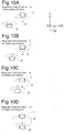
- Figs. 12A to 12C are explanatory views of changes in magnetic lines associated with movement of a soft magnetic body 5 in a magnetic position detection device according to a seventh embodiment of the present invention.
- Fig. 13 is a graph of an example of a relationship between a magnetic field direction (angle) at a position of the magnetic detection element 2 (detection position) and a movement amount of the soft magnetic body 5 in the magnetic position detection device of Figs. 12A to 12C .
- an angle ( ⁇ ) of the vertical axis is an angle in the counterclockwise direction starting from the +X-direction.
- the magnetic position detection device of this embodiment is different in that the object magnet 3 is replaced with the soft magnetic body 5, and is identical in terms of the other points.
- the soft magnetic body 5 is fixed to a mobile object not shown and moves in the X-direction as the mobile object moves.
- the X-directional movement amount of the soft magnetic body 5 corresponds to the magnetic field direction (angle) in a one-to-one relationship
- the movement amount (position) of the soft magnetic body 5 and the mobile object can be detected (uniquely identified) based on the output of the magnetic detection element 2 corresponding to the magnetic field direction.
- the replacement of the object magnet 3 with the soft magnetic body 5 makes the angle variation of the magnetic field acquired at the position of the magnetic detection element 2 smaller so that the stroke range becomes smaller, preferable position detection is enabled even when the detection object is the soft magnetic body 5.
- Figs. 14A to 14C are explanatory views of changes in magnetic lines associated with movement of the soft magnetic body 5 in a magnetic position detection device according to an eighth embodiment of the present invention.
- Fig. 15 is a graph of an example of a relationship between a magnetic field direction (angle) at a position of the magnetic detection element 2 (detection position) and a movement amount of the soft magnetic body 5 in the magnetic position detection device of Figs. 14A to 14C .
- an angle ( ⁇ ) of the vertical axis is an angle in the counterclockwise direction starting from the +X-direction.
- the magnetic position detection device of this embodiment is different in that the direction of the bias magnet 1 is changed clockwise by 90 degrees, and is identical in terms of the other points.
- the movement amount (position) of the soft magnetic body 5 and the mobile object can be detected (uniquely identified) based on the output of the magnetic detection element 2 corresponding to the magnetic field direction.
- This embodiment can produce the same effects as the seventh embodiment.
- the relative dimensional relationship between the bias magnet 1 and the object magnet 3 or the soft magnetic body 5 and the relative disposition of the magnetic detection element 2 are not limited to the examples described in the embodiments and are arbitrary as long as a magnetic field rotating in accordance with the movement of the object magnet 3 is acquired at the position of the magnetic detection element 2.
- the object magnet 3 may be a ring-shaped magnet circling around the mobile object around the X-axis.
- the cross section acquired by cutting the object magnet 3 along the YZ plane may be more flattened shape than the same cross section of the bias magnet 1.
- the bias magnet 1 and the magnetic detection element 2 are fixed while the object magnet 3 or the soft magnetic body 5 moves in the description of the embodiments, the object magnet 3 or the soft magnetic body 5 may be fixed while the bias magnet 1 and the magnetic detection element 2 move. In other words, a set of the bias magnet 1 and the magnetic detection element 2, and the object magnet 3 or the soft magnetic body 5 may move relative to each other, and which one actually moves is arbitrary.
Abstract
Description
- The present invention relates to a magnetic position detection device using a magnetic detection element and utilized for a position sensor and a stroke sensor, for example.
- In conventionally known magnetic position detection devices, four spin-valve magnetic resistance elements are arranged at the same position with respect to a magnetic pole arrangement direction of magnetic members having N-poles and S-poles alternatively magnetized.
-
- Patent Document 1: Japanese Patent No.
5013146 - Patent Document 2: Japanese Laid-Open Patent Publication No.
2006-23179 - Although conventional techniques require multiple magnets to be detected (object magnets), multiple object magnets cannot be arranged in some cases due to restriction on space. Using only one object magnetic leads to a problem of a narrow detectable stroke range. Additionally, objects to be detected are limited to magnets.
- The present invention was conceived in view of the situations and it is therefore a first object of the present invention to provide a magnetic position detection device capable of preferable position detection even when only one object magnet is used.
- A second object of the present invention is to provide a magnetic position detection device capable of preferable position detection even when an object to be detected is a soft magnetic body.
- A first aspect of the present invention is a magnetic position detection device. The magnetic position detection device comprises:
- a bias magnet; an object magnet; and a magnetic detection element detecting a direction of an applied magnetic field, wherein
- a movement of the object magnet relative to the bias magnet changes a magnetic field direction at a position of the magnetic detection element, and
- when the bias magnet and the object magnet come closest to each other, a magnetic field generated by the object magnet is larger than a magnetic field generated by the bias magnet at the position of the magnetic detection element.
- When the bias magnet is right in front of the object magnet, the same poles may face each other between the object magnet and the bias magnet.
- A magnetic pole surface of the bias magnet facing toward the object magnet and a magnetic pole surface of the object magnet facing toward the bias magnet may be substantially parallel to, and the same in polarity as, each other and may be substantially parallel to a relative movement direction of the object magnet.
- A magnetic pole surface of the bias magnet facing toward the object magnet and a magnetic pole surface of the object magnet facing toward the bias magnet may be substantially parallel to, and different in polarity from, each other and may be substantially parallel to a relative movement direction of the object magnet.
- A magnetic pole surface of the bias magnet and a magnetic pole surface of the object magnet may be substantially parallel to each other and may be substantially perpendicular to a relative movement direction of the object magnet.
- A magnetic pole surface of the bias magnet and a magnetic pole surface of the object magnet may be substantially perpendicular to each other.
- A second aspect of the present invention is a magnetic position detection device. The magnetic position detection device comprises:
- a bias magnet;
- an object magnet facing the bias magnet such that different poles face each other; and
- a magnetic detection element detecting a direction of an applied magnetic field, wherein
- a movement of the object magnet relative to the bias magnet changes a magnetic field direction at a position of the magnetic detection element.
- A magnetic pole surface of the object magnet may have a length related to a direction of the relative movement longer than that of a magnetic pole surface of the bias magnet.
- A position of the object magnet relative to the bias magnet may be uniquely identifiable.
- The magnetic detection element may be located at a position coming closer to the object magnet than the bias magnet when the bias magnet is right in front of the object magnet.
- The only one object magnet may be included.
- A third embodiment of the present invention is a magnetic position detection device. The magnetic position detection device comprises:
- a bias magnet; a soft magnetic body; and a magnetic detection element detecting a direction of an applied magnetic field, wherein
- a movement of the soft magnetic body relative to the bias magnet changes a magnetic field direction at a position of the magnetic detection element, and
- a position of the soft magnetic body relative to the bias magnet is uniquely identifiable.
- It is to be noted that any arbitrary combination of the above-described structural components as well as the expressions according to the present invention changed among a system and so forth are all effective as and encompassed by the present aspects.
- The first and second aspects of the present invention can provide the magnetic position detection device capable of favorable position detection even when only one object magnet is used.
- The third aspect of the present invention can provide the magnetic position detection device capable of favorable position detection even when an object to be detected is a soft magnetic body.
-
-
Fig. 1 is a schematic configuration diagram of a magnetic position detection device according to a first embodiment of the present invention. -
Fig. 2 is a graph of an example of a relationship between a magnetic field direction (angle) at a position of a magnetic detection element 2 (detection position) and a movement amount of anobject magnet 3, in the magnetic position detection device ofFig. 1 . -
Figs. 3A to 3C are explanatory views of changes in magnetic lines associated with movement of theobject magnet 3 in the magnetic position detection device ofFig. 1 . -
Fig. 4 is a schematic configuration diagram of a magnetic position detection device according to a second embodiment of the present invention. -
Fig. 5 is a schematic configuration diagram of a magnetic position detection device according to a third embodiment of the present invention. -
Fig. 6 is a graph of an example of a relationship between a magnetic field direction (angle) at a position of the magnetic detection element 2 (detection position) and a movement amount of theobject magnet 3, in the magnetic position detection device ofFig. 5 . -
Figs. 7A to 7F are explanatory views of changes in magnetic lines associated with movement of theobject magnet 3 in the magnetic position detection device ofFig. 5 . -
Figs. 8A to 8H are explanatory views of changes in magnetic lines associated with movement of theobject magnet 3 in a magnetic position detection device according to a fourth embodiment of the present invention. -
Fig. 9 is a graph of an example of a relationship between a magnetic field direction (angle) at a position of the magnetic detection element 2 (detection position) and a movement amount of theobject magnet 3, in the magnetic position detection device ofFigs. 8A to 8H . -
Figs. 10A to 10G are explanatory views of changes in magnetic lines associated with movement of theobject magnet 3 in a magnetic position detection device according to a fifth embodiment of the present invention. -
Figs. 11A to 11G are explanatory views of changes in magnetic lines associated with movement of theobject magnet 3 in a magnetic position detection device according to a sixth embodiment of the present invention. -
Figs. 12A to 12C are explanatory views of changes in magnetic lines associated with movement of asoft magnet body 5 in a magnetic position detection device according to a seventh embodiment of the present invention. -
Fig. 13 is a graph of an example of a relationship between a magnetic field direction (angle) at a position of the magnetic detection element 2 (detection position) and a movement amount of thesoft magnet body 5, in the magnetic position detection device ofFigs. 12A to 12C . -
Figs. 14A to 14C are explanatory views of changes in magnetic lines associated with movement of the softmagnetic body 5 in a magnetic position detection device according to an eighth embodiment of the present invention. -
Fig. 15 is a graph of an example of a relationship between a magnetic field direction (angle) at a position of the magnetic detection element 2 (detection position) and a movement amount of the softmagnetic body 5 in the magnetic position detection device ofFigs. 14A to 14C . - Now, preferred embodiments of the present invention will be described in detail, referring to the drawings. The same or equivalent constituent elements, members and so on which are shown in the respective drawings are denoted with the same reference numerals, and overlapped descriptions are appropriately omitted. Moreover, the present invention is not limited to the embodiments, but the embodiments are only examples. All features and the combinations of the features which are described in the embodiments are not absolutely essential to the present invention.
-
Fig. 1 is a schematic configuration diagram of a magnetic position detection device according to a first embodiment of the present invention. InFig. 1 , X-direction, Y-direction, and Z-direction are defined as three orthogonal directions.Fig. 1 also shows a portion of magnetic lines generated by abias magnet 1 and anobject magnet 3. The magnetic position detection device of this embodiment includes thebias magnet 1, amagnetic detection element 2, theobject magnet 3, and amobile object 4. - The
bias magnet 1 and theobject magnet 3 are preferably rare-earth magnets such as neodymium magnets and are formed into a columnar shape or a prismatic shape, for example, and arranged such that different poles face each other. In the shown example, the S-pole surface of thebias magnet 1 and the N-pole surface of theobject magnet 3 face each other. The facing magnetic pole surfaces of thebias magnet 1 and theobject magnet 3 are both parallel to the XZ plane. The non-facing magnetic pole surfaces of thebias magnet 1 and theobject magnet 3 are also both parallel to the XZ plane. Preferably, the facing magnetic pole surface of theobject magnet 3 has a length related to a relative movement direction (X-direction, or X- and Y-directions) longer than that of the facing magnetic pole surface of thebias magnet 1. Preferably, theobject magnet 3 has a more flattened shape than thebias magnet 1. - The
magnetic detection element 2 is disposed in front of the S-pole surface of the bias magnet 1 (the facing magnetic pole surface toward the object magnet 3). Themagnetic detection element 2 is fixedly disposed relative to thebias magnet 1 so as to fix a relative positional relationship with thebias magnet 1. The X-directional position of themagnetic detection element 2 is preferably identical to the X-directional position of the center of thebias magnet 1. Themagnetic detection element 2 detects a direction of a magnetic field applied thereto and is implemented by, for example, a combination of multiple Hall elements and a magnetic yoke, or a combination of multiple spin-valve magnetic resistance elements (see Patent Document 1: Japanese Patent No.5013146 magnetic detection element 2 is disposed at a position located closer to theobject magnet 3 than thebias magnet 1 when thebias magnet 1 is right in front of the object magnet 3 (come closest to each other) as shown inFig. 1 . Preferably, theobject magnet 3 has a magnetic force stronger than thebias magnet 1. In the case of themagnetic detection element 2 capable of detecting two-component detection (XY-component detection), thebias magnet 1, themagnetic detection element 2, and theobject magnet 3 preferably have the centers at the Z-directional positions made identical to each other. Theobject magnet 3 is fixed to themobile object 4 and moves in the X-direction as themobile object 4 moves. On the other hand, in the case of themagnetic detection element 2 capable of detecting three-component detection (XYZ-component detection), a two-dimensional position of theobject magnet 3 can be detected in the XZ plane, and theobject magnet 3 may move in the XZ plane along with themobile object 4. The movement of theobject magnet 3 changes the magnetic field direction at the position of themagnetic detection element 2. -
Fig. 2 is a graph of an example of a relationship between a magnetic field direction (angle) at a position of the magnetic detection element 2 (detection position) and a movement amount of theobject magnet 3 in the magnetic position detection device ofFig. 1 . InFig. 2 , an angle (θ) of the vertical axis is an angle in the clockwise direction starting from the +Y-direction.Figs. 3A to 3C are explanatory views of changes in magnetic lines associated with movement of theobject magnet 3 in the magnetic position detection device ofFig. 1 .Figs. 3A to 3C show a portion in the vicinity of the center of the stroke range of theobject magnet 3 and, actually, as shown inFig. 2 , the magnetic field direction at the position of themagnetic detection element 2 changes in a range exceeding ±80 degrees. As shown inFigs. 3A to 3C , as theobject magnet 3 and themobile object 4 move rightward (in the +X-direction), the magnetic field rotates counterclockwise at the position of themagnetic detection element 2. Conversely, if theobject magnet 3 and themobile object 4 move leftward (in the -X-direction), the magnetic field rotates clockwise at the position of themagnetic detection element 2. In this way, a magnetic flux between thebias magnet 1 and theobject magnet 3 has a vector changing like a pendulum at thebias magnet 1 as a supporting point in accordance with the movement of theobject magnet 3 and themobile object 4 in the ±X-directions. By detecting this vector change with themagnetic detection element 2, the position of theobject magnet 3 and themobile object 4 can be detected. As can be seen fromFig. 2 , the magnetic field direction at the position of themagnetic detection element 2 changes in accordance with changes in the X-directional movement amount of theobject magnet 3 and, since the X-directional movement amount of theobject magnet 3 corresponds to the magnetic field direction (angle) in a one-to-one relationship, the movement amount (position) of theobject magnet 3 and themobile object 4 can be detected (uniquely identified) based on the output of themagnetic detection element 2 corresponding to the magnetic field direction. - This embodiment can produce the following effects.
-
- (1) Since the
bias magnet 1 is disposed behind themagnetic detection element 2, and thebias magnet 1 and theobject magnet 3 are arranged such that different poles face each other, a detectable stroke range can be widened despite of the oneobject magnet 3. Therefore, even when a restriction on space exists making it unable to dispose themultiple object magnets 3, preferable position detection is enabled. - (2) Since the magnetic field at the position of the
magnetic detection element 2 is strengthened by disposing thebias magnet 1, the magnetic field strength required for detection can be ensured even when themagnetic detection element 2 is more away from theobject magnet 3 as compared to the case without thebias magnet 1, and a degree of freedom of layout is increased. - (3) Since the
object magnet 3 is formed into a more flattened shape than thebias magnet 1 and the facing magnetic pole surface of theobject magnet 3 has a length related to the movement direction made longer than that of the facing magnetic pole surface of thebias magnet 1, the magnetic flux of theobject magnet 3 spreads in the X-direction and thebias magnet 1 strongly attracts the magnetic flux in the Y-direction in a narrow range. Since themagnetic detection element 2 is disposed at a position located closer to theobject magnet 3 than thebias magnet 1 when thebias magnet 1 is right in front of theobject magnet 3, the magnetic field rotating in accordance with the movement of theobject magnet 3 can be acquired in a wide stroke range at the position of themagnetic detection element 2. Additionally, theobject magnet 3 has a magnetic force stronger than thebias magnet 1, this also leads to a wider stroke range (the magnetic field direction can be changed by nearly 180 degrees at the position of themagnetic detection element 2 in accordance with the movement of the object magnet 3). -
Fig. 4 is a schematic configuration diagram of a magnetic position detection device according to a second embodiment of the present invention. The magnetic position detection device of this embodiment is different from the device of the first embodiment shown inFig. 1 etc. in that the twobias magnets 1 are included. When the twobias magnets 1 are included, the X-direction position of themagnetic detection element 2 is made identical to the center of the gap between thebias magnets 1, and the other points are the same as the case shown inFig. 1 . This embodiment can produce the same effects as the first embodiment. -
Fig. 5 is a schematic configuration diagram of a magnetic position detection device according to a third embodiment of the present invention. InFig. 5 , X-direction, Y-direction, and Z-direction are three orthogonal directions defined in the same way asFig. 1 .Fig. 5 also shows a portion of magnetic lines generated by thebias magnet 1 and theobject magnet 3. In the magnetic position detection device of this embodiment, unlike the device of the first embodiment shown inFig. 1 etc., thebias magnet 1 and theobject magnet 3 are arranged such that the same poles face each other. In the shown example, the N-pole surface of thebias magnet 1 and the N-pole surface of theobject magnet 3 face each other. The facing magnetic pole surfaces of thebias magnet 1 and theobject magnet 3 are both parallel to the XZ plane. The non-facing magnetic pole surfaces of thebias magnet 1 and theobject magnet 3 are also both parallel to the XZ plane. - The
magnetic detection element 2 is disposed in front of the N-pole surface of the bias magnet 1 (the facing magnetic pole surface toward the object magnet 3). Themagnetic detection element 2 is fixedly disposed relative to thebias magnet 1 so as to fix a relative positional relationship with thebias magnet 1. The X-directional position of themagnetic detection element 2 is preferably identical to the X-directional position of the center of thebias magnet 1. Preferably, themagnetic detection element 2 is disposed at a position located closer to theobject magnet 3 than thebias magnet 1 when thebias magnet 1 is right in front of the object magnet 3 (come closest to each other) as shown inFig. 5 . This is because when thebias magnet 1 is right in front of theobject magnet 3, the magnetic field generated by theobject magnet 3 is made larger than the magnetic field generated by thebias magnet 1 at the position of themagnetic detection element 2. As a result, when thebias magnet 1 is right in front of theobject magnet 3, the magnetic field direction at the position of themagnetic detection element 2 can be directed in the +Y-direction (upward) and, as described later, the magnetic field direction can be rotated by approx. 360 degrees at the position of themagnetic detection element 2 in accordance with the movement of theobject magnet 3. In the case of themagnetic detection element 2 capable of detecting two-component detection (XY-component detection), thebias magnet 1, themagnetic detection element 2, and theobject magnet 3 preferably have the centers at the Z-directional positions made identical to each other. Theobject magnet 3 is fixed to themobile object 4 and moves in the X-direction as themobile object 4 moves. On the other hand, in the case of themagnetic detection element 2 capable of detecting three-component detection (XYZ-component detection), a two-dimensional position of theobject magnet 3 can be detected in the XZ plane, and theobject magnet 3 may move in the XZ plane along with themobile object 4. The movement of theobject magnet 3 changes the magnetic field direction at the position of themagnetic detection element 2. -
Fig. 6 is a graph of an example of a relationship between a magnetic field direction (angle) at a position of the magnetic detection element 2 (detection position) and a movement amount of theobject magnet 3 in the magnetic position detection device ofFig. 5 . InFig. 6 , an angle (θ) of the vertical axis is an angle in the counterclockwise direction starting from the +X-direction.Figs. 7A to 7F are explanatory views of changes in magnetic lines associated with movement of theobject magnet 3 in the magnetic position detection device ofFig. 5 .Figs. 7A to 7F show a portion of the stroke range of theobject magnet 3 and, actually, as shown inFig. 6 , the magnetic field direction at the position of themagnetic detection element 2 is changed by approx. 360 degrees in accordance with relative movement of theobject magnet 3. As shown inFigs. 7A to 7F , as theobject magnet 3 and themobile object 4 move rightward (in the +X-direction), the magnetic field rotates counterclockwise at the position of themagnetic detection element 2. Conversely, if theobject magnet 3 and themobile object 4 move leftward (in the -X-direction), the magnetic field rotates clockwise at the position of themagnetic detection element 2. In this way, a magnetic flux between thebias magnet 1 and theobject magnet 3 has a vector changing in a rotating manner around the position of themagnetic detection element 2 in accordance with the movement of theobject magnet 3 and themobile object 4 in the ±X-directions. By detecting this vector change with themagnetic detection element 2, the position of theobject magnet 3 and themobile object 4 can be detected. As can be seen fromFig. 6 , the magnetic field direction at the position of themagnetic detection element 2 changes in accordance with changes in the X-directional movement amount of theobject magnet 3 and, since the X-directional movement amount of theobject magnet 3 corresponds to the magnetic field direction (angle) in a one-to-one relationship, the movement amount (position) of theobject magnet 3 and themobile object 4 can be detected (uniquely identified) based on the output of themagnetic detection element 2 corresponding to the magnetic field direction. - According to this embodiment, since the magnetic field direction at the position of the
magnetic detection element 2 is changed by approx. 360 degrees in accordance with the relative movement of theobject magnet 3, a wider stroke range can be ensured as compared to the first embodiment in which the magnetic field direction is changed by 180 degrees or less. -
Figs. 8A to 8H are explanatory views of changes in magnetic lines associated with movement of theobject magnet 3 in a magnetic position detection device according to a fourth embodiment of the present invention. InFigs. 8A to 8H , a mobile object having theobject magnet 3 fixed thereto and moving along with theobject magnet 3 is not shown.Fig. 9 is a graph of an example of a relationship between a magnetic field direction (angle) at a position of the magnetic detection element 2 (detection position) and a movement amount of theobject magnet 3 in the magnetic position detection device ofFigs. 8A to 8H . InFig. 9 , an angle (θ) of the vertical axis is an angle in the counterclockwise direction starting from the -X-direction. - In the magnetic position detection device of this embodiment, unlike the device of the first embodiment shown in
Fig. 1 etc., the magnetic pole surfaces of thebias magnet 1 and the magnetic pole surfaces of theobject magnet 3 are perpendicular to each other. In this embodiment, the magnetic pole surfaces of thebias magnet 1 are parallel to the YZ plane, and the magnetic pole surfaces of theobject magnet 3 are parallel to the XZ plane. Themagnetic detection element 2 is disposed in front of a non-magnetic pole surface of thebias magnet 1 facing toward theobject magnet 3. Themagnetic detection element 2 is fixedly disposed relative to thebias magnet 1 so as to fix a relative positional relationship with thebias magnet 1. The X-directional position of themagnetic detection element 2 is preferably identical to the X-directional position of the center of thebias magnet 1. Preferably, themagnetic detection element 2 is disposed at a position located closer to theobject magnet 3 than thebias magnet 1 when thebias magnet 1 is right in front of the object magnet 3 (come closest to each other). In the case of themagnetic detection element 2 capable of detecting two-component detection (XY-component detection), thebias magnet 1, themagnetic detection element 2, and theobject magnet 3 preferably have the centers at the Z-directional positions made identical to each other. On the other hand, in the case of themagnetic detection element 2 capable of detecting three-component detection (XYZ-component detection), a two-dimensional position of theobject magnet 3 can be detected in the XZ plane, and theobject magnet 3 may move in the XZ plane. The movement of theobject magnet 3 changes the magnetic field direction at the position of themagnetic detection element 2. - In the range shown in
Figs. 8A to 8E , as theobject magnet 3 moves rightward (in the +X-direction), the magnetic field rotates counterclockwise at the position of themagnetic detection element 2. Conversely, if theobject magnet 3 moves leftward (in the -X-direction) in the same range, the magnetic field rotates clockwise at the position of themagnetic detection element 2. In this way, a magnetic flux between thebias magnet 1 and theobject magnet 3 has a vector changing in a rotating manner around the position of themagnetic detection element 2 in accordance with the movement of theobject magnet 3 in the ±X-directions. - In the range shown in
Figs. 8E to 8H , the magnetic field at the position of themagnetic detection element 2 has a vector changing like a pendulum in the vertical direction inFigs. 8E to 8H in a range within 180 degrees in accordance with the movement of theobject magnet 3 in the ±X-directions. - By detecting these vector changes with the
magnetic detection element 2, the position of theobject magnet 3 can be detected. As shown inFig. 9 , since the magnetic field direction at the position of themagnetic detection element 2 is changed by approx. 400 degrees in the case of the relative movement of theobject magnet 3 within the range shown inFigs. 8A to 8H , the stroke range of theobject magnet 3 is limited to, for example, a range of X1 or a range of X2 shown inFig. 9 . As a result, since the X-directional movement amount of theobject magnet 3 corresponds to the magnetic field direction (angle) in a one-to-one relationship, the movement amount (position) of theobject magnet 3 can be detected (uniquely identified) based on the output of themagnetic detection element 2 corresponding to the magnetic field direction. -
Figs. 10A to 10G are explanatory views of changes in magnetic lines associated with movement of theobject magnet 3 in a magnetic position detection device according to a fifth embodiment of the present invention. InFigs. 10A to 10G , a mobile object having theobject magnet 3 fixed thereto and moving along with theobject magnet 3 is not shown. In the magnetic position detection device of this embodiment, unlike the device of the first embodiment shown inFig. 1 etc., the magnetic pole surfaces of thebias magnet 1 and the magnetic pole surfaces of theobject magnet 3 are substantially parallel to each other and substantially perpendicular to the relative movement direction (X-direction) of the object magnet 3 (substantially parallel to the YZ plane). Thebias magnet 1 and theobject magnet 3 are arranged such that the same poles face each other. Specifically, in the state ofFigs. 10A and 10B , the S-poles face each other and, in the state ofFigs. 10F and 10G , the N-poles face each other. Themagnetic detection element 2 is disposed in front of a non-magnetic pole surface of thebias magnet 1 facing toward theobject magnet 3. Themagnetic detection element 2 is fixedly disposed relative to thebias magnet 1 so as to fix a relative positional relationship with thebias magnet 1. The X-directional position of themagnetic detection element 2 is preferably identical to the X-directional position of the center of thebias magnet 1. Preferably, themagnetic detection element 2 is disposed at a position located closer to theobject magnet 3 than thebias magnet 1 when thebias magnet 1 is right in front of the object magnet 3 (come closest to each other). This is because when thebias magnet 1 is right in front of theobject magnet 3 as shown inFig. 10D , the magnetic field generated by theobject magnet 3 is made larger than the magnetic field generated by thebias magnet 1 at the position of themagnetic detection element 2. As a result, when thebias magnet 1 is right in front of theobject magnet 3, the magnetic field direction at the position of themagnetic detection element 2 can be directed in the +X-direction (rightward) and the magnetic field direction can be rotated by approx. 360 degrees at the position of themagnetic detection element 2 in accordance with the movement of theobject magnet 3. In the case of themagnetic detection element 2 capable of detecting two-component detection (XY-component detection), thebias magnet 1, themagnetic detection element 2, and theobject magnet 3 preferably have the centers at the Z-directional positions made identical to each other. On the other hand, in the case of themagnetic detection element 2 capable of detecting three-component detection (XYZ-component detection), a two-dimensional position of theobject magnet 3 can be detected in the XZ plane, and theobject magnet 3 may move in the XZ plane. The movement of theobject magnet 3 changes the magnetic field direction at the position of themagnetic detection element 2 - As shown in
Figs. 10A to 10G , as theobject magnet 3 moves rightward (in the +X-direction), the magnetic field rotates counterclockwise at the position of themagnetic detection element 2. Conversely, if theobject magnet 3 moves leftward (in the -X-direction) in the same range, the magnetic field rotates clockwise at the position of themagnetic detection element 2. In this way, a magnetic flux between thebias magnet 1 and theobject magnet 3 has a vector changing in a rotating manner around the position of themagnetic detection element 2 in accordance with the movement of theobject magnet 3 in the ±X-directions. By detecting this vector change with themagnetic detection element 2, the position of theobject magnet 3 can be detected. The magnetic field direction at the position of the magnetic detection element 2 (the angle θ in the counterclockwise direction starting from the -Z-direction) is changed in accordance with the movement of theobject magnet 3 as is the case withFig. 6 , and the movement amount (position) of theobject magnet 3 can be detected (uniquely identified) based on the output of themagnetic detection element 2 corresponding to the magnetic field direction. -
Figs. 11A to 11G are explanatory views of changes in magnetic lines associated with movement of theobject magnet 3 in a magnetic position detection device according to a sixth embodiment of the present invention. InFigs. 11A to 11G , a mobile object having theobject magnet 3 fixed thereto and moving along with theobject magnet 3 is not shown. As compared to the device of the fifth embodiment shown inFigs. 10A to 10G , the magnetic position detection device of this embodiment is different in that the N- and P-poles of theobject magnet 3 are inverted, and is identical in terms of the other points. As shown inFigs. 11A to 11G , as theobject magnet 3 moves rightward (in the +X-direction), the magnetic field rotates counterclockwise at the position of themagnetic detection element 2. Conversely, if theobject magnet 3 moves leftward (in the -X-direction) in the same range, the magnetic field rotates clockwise at the position of themagnetic detection element 2. In this way, a magnetic flux between thebias magnet 1 and theobject magnet 3 has a vector changing like a pendulum in accordance with the movement of theobject magnet 3 in the ±X-directions. By detecting this vector change with themagnetic detection element 2, the position of theobject magnet 3 can be detected. The magnetic field direction at the position of the magnetic detection element 2 (the angle θ in the counterclockwise direction starting from the -X-direction) is changed in accordance with the movement of theobject magnet 3 as is the case withFig. 2 , and the movement amount (position) of theobject magnet 3 can be detected (uniquely identified) based on the output of themagnetic detection element 2 corresponding to the magnetic field direction. Also in this embodiment, by using theobject magnet 3 having a magnetic force stronger than thebias magnet 1, the stroke range can be widened (the magnetic field direction can be changed by nearly 180 degrees at the position of themagnetic detection element 2 in accordance with the movement of the object magnet 3). -
Figs. 12A to 12C are explanatory views of changes in magnetic lines associated with movement of a softmagnetic body 5 in a magnetic position detection device according to a seventh embodiment of the present invention.Fig. 13 is a graph of an example of a relationship between a magnetic field direction (angle) at a position of the magnetic detection element 2 (detection position) and a movement amount of the softmagnetic body 5 in the magnetic position detection device ofFigs. 12A to 12C . InFig. 13 , an angle (θ) of the vertical axis is an angle in the counterclockwise direction starting from the +X-direction. As compared to the device of the third embodiment shown inFig. 5 etc., the magnetic position detection device of this embodiment is different in that theobject magnet 3 is replaced with the softmagnetic body 5, and is identical in terms of the other points. The softmagnetic body 5 is fixed to a mobile object not shown and moves in the X-direction as the mobile object moves. As shown inFig. 13 , since the X-directional movement amount of the softmagnetic body 5 corresponds to the magnetic field direction (angle) in a one-to-one relationship, the movement amount (position) of the softmagnetic body 5 and the mobile object can be detected (uniquely identified) based on the output of themagnetic detection element 2 corresponding to the magnetic field direction. According to this embodiment, although the replacement of theobject magnet 3 with the softmagnetic body 5 makes the angle variation of the magnetic field acquired at the position of themagnetic detection element 2 smaller so that the stroke range becomes smaller, preferable position detection is enabled even when the detection object is the softmagnetic body 5. -
Figs. 14A to 14C are explanatory views of changes in magnetic lines associated with movement of the softmagnetic body 5 in a magnetic position detection device according to an eighth embodiment of the present invention.Fig. 15 is a graph of an example of a relationship between a magnetic field direction (angle) at a position of the magnetic detection element 2 (detection position) and a movement amount of the softmagnetic body 5 in the magnetic position detection device ofFigs. 14A to 14C . InFigs. 14A to 14C , an angle (θ) of the vertical axis is an angle in the counterclockwise direction starting from the +X-direction. As compared to the device of the seventh embodiment shown inFigs. 12A to 12C , the magnetic position detection device of this embodiment is different in that the direction of thebias magnet 1 is changed clockwise by 90 degrees, and is identical in terms of the other points. As shown inFig. 15 , since the X-directional movement amount of the softmagnetic body 5 corresponds to the magnetic field direction (angle) in a one-to-one relationship, the movement amount (position) of the softmagnetic body 5 and the mobile object can be detected (uniquely identified) based on the output of themagnetic detection element 2 corresponding to the magnetic field direction. This embodiment can produce the same effects as the seventh embodiment. - Although the present invention has been described by taking the embodiments as examples, it is understood by those skilled in the art that the constituent elements of the embodiments are variously modifiable within the scope of claims. Modification examples will hereinafter be mentioned.
- The relative dimensional relationship between the
bias magnet 1 and theobject magnet 3 or the softmagnetic body 5 and the relative disposition of themagnetic detection element 2 are not limited to the examples described in the embodiments and are arbitrary as long as a magnetic field rotating in accordance with the movement of theobject magnet 3 is acquired at the position of themagnetic detection element 2. - In the first to sixth embodiments, the
object magnet 3 may be a ring-shaped magnet circling around the mobile object around the X-axis. In this case, in the first embodiment, the cross section acquired by cutting theobject magnet 3 along the YZ plane may be more flattened shape than the same cross section of thebias magnet 1. Although thebias magnet 1 and themagnetic detection element 2 are fixed while theobject magnet 3 or the softmagnetic body 5 moves in the description of the embodiments, theobject magnet 3 or the softmagnetic body 5 may be fixed while thebias magnet 1 and themagnetic detection element 2 move. In other words, a set of thebias magnet 1 and themagnetic detection element 2, and theobject magnet 3 or the softmagnetic body 5 may move relative to each other, and which one actually moves is arbitrary. -
- 1
- Bias magnet
- 2
- Magnetic detection element
- 3
- Object magnet
- 4
- Mobile object
- 5
- Soft magnetic body
Claims (12)
- A magnetic position detection device comprising:a bias magnet; an object magnet; and a magnetic detection element detecting a direction of an applied magnetic field, whereina movement of the object magnet relative to the bias magnet changes a magnetic field direction at a position of the magnetic detection element, andwhen the bias magnet and the object magnet come closest to each other, a magnetic field generated by the object magnet is larger than a magnetic field generated by the bias magnet at the position of the magnetic detection element.
- The magnetic position detection device according to claim 1, wherein when the bias magnet is right in front of the object magnet, the same poles face each other between the object magnet and the bias magnet.
- The magnetic position detection device according to claim 1, wherein a magnetic pole surface of the bias magnet facing toward the object magnet and a magnetic pole surface of the object magnet facing toward the bias magnet are substantially parallel to, and the same in polarity as, each other and are substantially parallel to a relative movement direction of the object magnet.
- The magnetic position detection device according to claim 1, wherein a magnetic pole surface of the bias magnet facing toward the object magnet and a magnetic pole surface of the object magnet facing toward the bias magnet are substantially parallel to, and different in polarity from, each other and are substantially parallel to a relative movement direction of the object magnet.
- The magnetic position detection device according to claim 1, wherein a magnetic pole surface of the bias magnet and a magnetic pole surface of the object magnet are substantially parallel to each other and are substantially perpendicular to a relative movement direction of the object magnet.
- The magnetic position detection device according to claim 1, wherein a magnetic pole surface of the bias magnet and a magnetic pole surface of the object magnet are substantially perpendicular to each other.
- A magnetic position detection device comprising:a bias magnet;an object magnet facing the bias magnet such that different poles face each other; anda magnetic detection element detecting a direction of an applied magnetic field, whereina movement of the object magnet relative to the bias magnet changes a magnetic field direction at a position of the magnetic detection element.
- The magnetic position detection device according to claim 7, wherein a magnetic pole surface of the object magnet has a length related to a direction of the relative movement longer than that of a magnetic pole surface of the bias magnet.
- The magnetic position detection device according to any one of claims 1 to 8, wherein a position of the object magnet relative to the bias magnet is uniquely identifiable.
- The magnetic position detection device according to any one of claims 1 to 9, wherein the magnetic detection element is located at a position coming closer to the object magnet than the bias magnet when the bias magnet is right in front of the object magnet.
- The magnetic position detection device according to any one of claims 1 to 10, wherein the only one object magnet is included.
- A magnetic position detection device comprising:a bias magnet; a soft magnetic body; and a magnetic detection element detecting a direction of an applied magnetic field, whereina movement of the soft magnetic body relative to the bias magnet changes a magnetic field direction at a position of the magnetic detection element, anda position of the soft magnetic body relative to the bias magnet is uniquely identifiable.
Applications Claiming Priority (2)
| Application Number | Priority Date | Filing Date | Title |
|---|---|---|---|
| JP2014171072 | 2014-08-26 | ||
| PCT/JP2015/052296 WO2016031261A1 (en) | 2014-08-26 | 2015-01-28 | Magnetic position detection device |
Publications (3)
| Publication Number | Publication Date |
|---|---|
| EP3187832A1 true EP3187832A1 (en) | 2017-07-05 |
| EP3187832A4 EP3187832A4 (en) | 2018-04-04 |
| EP3187832B1 EP3187832B1 (en) | 2020-10-14 |
Family
ID=55399170
Family Applications (1)
| Application Number | Title | Priority Date | Filing Date |
|---|---|---|---|
| EP15835725.1A Active EP3187832B1 (en) | 2014-08-26 | 2015-01-28 | Magnetic position detection device |
Country Status (5)
| Country | Link |
|---|---|
| US (1) | US20170122777A1 (en) |
| EP (1) | EP3187832B1 (en) |
| JP (1) | JP6406531B2 (en) |
| CN (1) | CN106461418A (en) |
| WO (1) | WO2016031261A1 (en) |
Families Citing this family (4)
| Publication number | Priority date | Publication date | Assignee | Title |
|---|---|---|---|---|
| AT521356B1 (en) * | 2018-07-18 | 2020-01-15 | Avl List Gmbh | Differential pressure transducer for a flow meter and flow meter |
| JP6824484B1 (en) * | 2020-03-10 | 2021-02-03 | 三菱電機株式会社 | Magnetic linear position detector |
| WO2021241717A1 (en) * | 2020-05-29 | 2021-12-02 | 日本精機株式会社 | Stroke sensor |
| JP7444143B2 (en) | 2021-07-20 | 2024-03-06 | Tdk株式会社 | magnetic sensor device |
Family Cites Families (21)
| Publication number | Priority date | Publication date | Assignee | Title |
|---|---|---|---|---|
| JPS576962Y2 (en) * | 1974-07-26 | 1982-02-09 | ||
| US4295118A (en) * | 1980-05-21 | 1981-10-13 | The Singer Company | Latching relay using Hall effect device |
| JPS61172079A (en) * | 1984-03-14 | 1986-08-02 | Matsushita Electric Works Ltd | Hall sensor |
| JPS61123910U (en) * | 1985-01-21 | 1986-08-04 | ||
| JPH04282481A (en) * | 1991-03-11 | 1992-10-07 | Matsushita Electric Ind Co Ltd | Magnetoelectric converter |
| JPH05175483A (en) * | 1991-12-24 | 1993-07-13 | Asahi Chem Ind Co Ltd | Positional sensor |
| DE69325165T2 (en) * | 1992-03-02 | 1999-10-28 | Seiko Epson Corp | DISPLACEMENT SENSOR |
| JP2000193407A (en) * | 1998-12-25 | 2000-07-14 | Tdk Corp | Magnetic positioning device |
| JP2002005613A (en) * | 2000-06-15 | 2002-01-09 | Yazaki Corp | Rotational angle detecting sensor |
| JP2003197078A (en) * | 2001-12-27 | 2003-07-11 | Takata Corp | Magnetic proximity switch and buckle switch |
| US6737862B1 (en) * | 2003-05-14 | 2004-05-18 | Delphi Technologies, Inc. | Magnetosensitive latch engagement detector for a mechanical fastening system |
| US7408343B2 (en) * | 2004-11-18 | 2008-08-05 | Honeywell International Inc. | Position detection utilizing an array of magnetic sensors with irregular spacing between sensing elements |
| US7427859B2 (en) * | 2005-08-10 | 2008-09-23 | Tdk Corporation | Moving body detecting apparatus |
| JP2008101932A (en) * | 2006-10-17 | 2008-05-01 | Tokai Rika Co Ltd | Magnetic position sensor |
| US7619407B2 (en) * | 2008-04-10 | 2009-11-17 | Magic Technologies, Inc. | Gear tooth sensor with single magnetoresistive bridge |
| JP2010243287A (en) * | 2009-04-03 | 2010-10-28 | Tokai Rika Co Ltd | Shift position detection device of vehicle |
| FR2953286B1 (en) * | 2009-11-27 | 2012-06-22 | Electricfil Automotive | METHOD AND MAGNETIC MEASURING SENSOR FOR NON-CONTACT DETECTION OF MOVEMENTS |
| JP5013146B2 (en) * | 2009-12-03 | 2012-08-29 | Tdk株式会社 | Magnetic position detector |
| JP5408508B2 (en) * | 2011-11-01 | 2014-02-05 | 株式会社デンソー | Position detection device |
| IN2014DN06822A (en) * | 2012-08-31 | 2015-05-22 | Toshiba Kk | |
| DE102013206518A1 (en) * | 2013-04-12 | 2014-10-16 | Zf Friedrichshafen Ag | Magnetic field sensor device, actuator and method for determining a relative position |
-
2015
- 2015-01-28 CN CN201580033386.9A patent/CN106461418A/en active Pending
- 2015-01-28 EP EP15835725.1A patent/EP3187832B1/en active Active
- 2015-01-28 JP JP2016544971A patent/JP6406531B2/en active Active
- 2015-01-28 US US15/317,483 patent/US20170122777A1/en not_active Abandoned
- 2015-01-28 WO PCT/JP2015/052296 patent/WO2016031261A1/en active Application Filing
Also Published As
| Publication number | Publication date |
|---|---|
| CN106461418A (en) | 2017-02-22 |
| WO2016031261A1 (en) | 2016-03-03 |
| US20170122777A1 (en) | 2017-05-04 |
| JP6406531B2 (en) | 2018-10-17 |
| JPWO2016031261A1 (en) | 2017-06-08 |
| EP3187832B1 (en) | 2020-10-14 |
| EP3187832A4 (en) | 2018-04-04 |
Similar Documents
| Publication | Publication Date | Title |
|---|---|---|
| EP3187832B1 (en) | Magnetic position detection device | |
| EP2330389B1 (en) | Magnetic position detector | |
| EP3368863B1 (en) | Methods and apparatus for phase offset selection in ring magnet sensing | |
| JP6067070B2 (en) | Magnetic field measuring device | |
| JP2009192261A (en) | Rectilinear displacement detector | |
| JP2009288158A (en) | Rotation angle detecting device | |
| JP2006294363A (en) | Magnetic proximity switch | |
| JP2013238485A (en) | Encoder and actuator using the same | |
| JP5653262B2 (en) | Stroke amount detection device | |
| CN113324564B (en) | Position detection device, position detection system using same, and steering system | |
| JP5500389B2 (en) | Stroke amount detection device | |
| EP2891894A2 (en) | Magnetic sensor | |
| WO2016171059A1 (en) | Position detecting device and structure for using position detecting device | |
| JP2013096723A (en) | Position detector | |
| JP2011169715A (en) | Position detection mechanism | |
| JP2013251175A (en) | Magnetic displacement detector | |
| US20160377453A1 (en) | Position detection device, control method, and storage medium | |
| JP2008241370A (en) | Magnet structure and position detector using the same | |
| JP2008241368A (en) | Magnet structure for angle sensor and angle sensor using the same | |
| JP2006308371A (en) | Noncontact rotary displacement sensor | |
| JP2021036203A (en) | Position detector | |
| JP2009236743A (en) | Magnetic position detecting device | |
| JP2013081520A (en) | Metal member detection device | |
| JP2011187024A (en) | Position detection system and multidirectional input device equipped with the same | |
| EP2860495A1 (en) | Angular sensor |
Legal Events
| Date | Code | Title | Description |
|---|---|---|---|
| STAA | Information on the status of an ep patent application or granted ep patent |
Free format text: STATUS: THE INTERNATIONAL PUBLICATION HAS BEEN MADE |
|
| PUAI | Public reference made under article 153(3) epc to a published international application that has entered the european phase |
Free format text: ORIGINAL CODE: 0009012 |
|
| STAA | Information on the status of an ep patent application or granted ep patent |
Free format text: STATUS: REQUEST FOR EXAMINATION WAS MADE |
|
| 17P | Request for examination filed |
Effective date: 20161229 |
|
| AK | Designated contracting states |
Kind code of ref document: A1 Designated state(s): AL AT BE BG CH CY CZ DE DK EE ES FI FR GB GR HR HU IE IS IT LI LT LU LV MC MK MT NL NO PL PT RO RS SE SI SK SM TR |
|
| AX | Request for extension of the european patent |
Extension state: BA ME |
|
| DAX | Request for extension of the european patent (deleted) | ||
| REG | Reference to a national code |
Ref country code: DE Ref legal event code: R079 Ref document number: 602015060583 Country of ref document: DE Free format text: PREVIOUS MAIN CLASS: G01D0005120000 Ipc: G01D0005140000 |
|
| A4 | Supplementary search report drawn up and despatched |
Effective date: 20180306 |
|
| RIC1 | Information provided on ipc code assigned before grant |
Ipc: G01D 5/14 20060101AFI20180228BHEP |
|
| STAA | Information on the status of an ep patent application or granted ep patent |
Free format text: STATUS: EXAMINATION IS IN PROGRESS |
|
| 17Q | First examination report despatched |
Effective date: 20181210 |
|
| GRAP | Despatch of communication of intention to grant a patent |
Free format text: ORIGINAL CODE: EPIDOSNIGR1 |
|
| STAA | Information on the status of an ep patent application or granted ep patent |
Free format text: STATUS: GRANT OF PATENT IS INTENDED |
|
| INTG | Intention to grant announced |
Effective date: 20200508 |
|
| GRAS | Grant fee paid |
Free format text: ORIGINAL CODE: EPIDOSNIGR3 |
|
| GRAA | (expected) grant |
Free format text: ORIGINAL CODE: 0009210 |
|
| STAA | Information on the status of an ep patent application or granted ep patent |
Free format text: STATUS: THE PATENT HAS BEEN GRANTED |
|
| RIN1 | Information on inventor provided before grant (corrected) |
Inventor name: SUZUKI, KEIJI Inventor name: MORIYA, TAKAHIRO Inventor name: NARITA, KAORU Inventor name: FUKUOKA, SEIJI Inventor name: HIRANO, HIROYUKI |
|
| AK | Designated contracting states |
Kind code of ref document: B1 Designated state(s): AL AT BE BG CH CY CZ DE DK EE ES FI FR GB GR HR HU IE IS IT LI LT LU LV MC MK MT NL NO PL PT RO RS SE SI SK SM TR |
|
| RAP1 | Party data changed (applicant data changed or rights of an application transferred) |
Owner name: TDK CORPORATION |
|
| REG | Reference to a national code |
Ref country code: GB Ref legal event code: FG4D |
|
| REG | Reference to a national code |
Ref country code: AT Ref legal event code: REF Ref document number: 1324015 Country of ref document: AT Kind code of ref document: T Effective date: 20201015 Ref country code: CH Ref legal event code: EP |
|
| REG | Reference to a national code |
Ref country code: DE Ref legal event code: R096 Ref document number: 602015060583 Country of ref document: DE |
|
| REG | Reference to a national code |
Ref country code: IE Ref legal event code: FG4D |
|
| REG | Reference to a national code |
Ref country code: AT Ref legal event code: MK05 Ref document number: 1324015 Country of ref document: AT Kind code of ref document: T Effective date: 20201014 |
|
| REG | Reference to a national code |
Ref country code: NL Ref legal event code: MP Effective date: 20201014 |
|
| PG25 | Lapsed in a contracting state [announced via postgrant information from national office to epo] |
Ref country code: RS Free format text: LAPSE BECAUSE OF FAILURE TO SUBMIT A TRANSLATION OF THE DESCRIPTION OR TO PAY THE FEE WITHIN THE PRESCRIBED TIME-LIMIT Effective date: 20201014 Ref country code: PT Free format text: LAPSE BECAUSE OF FAILURE TO SUBMIT A TRANSLATION OF THE DESCRIPTION OR TO PAY THE FEE WITHIN THE PRESCRIBED TIME-LIMIT Effective date: 20210215 Ref country code: FI Free format text: LAPSE BECAUSE OF FAILURE TO SUBMIT A TRANSLATION OF THE DESCRIPTION OR TO PAY THE FEE WITHIN THE PRESCRIBED TIME-LIMIT Effective date: 20201014 Ref country code: NL Free format text: LAPSE BECAUSE OF FAILURE TO SUBMIT A TRANSLATION OF THE DESCRIPTION OR TO PAY THE FEE WITHIN THE PRESCRIBED TIME-LIMIT Effective date: 20201014 Ref country code: NO Free format text: LAPSE BECAUSE OF FAILURE TO SUBMIT A TRANSLATION OF THE DESCRIPTION OR TO PAY THE FEE WITHIN THE PRESCRIBED TIME-LIMIT Effective date: 20210114 Ref country code: GR Free format text: LAPSE BECAUSE OF FAILURE TO SUBMIT A TRANSLATION OF THE DESCRIPTION OR TO PAY THE FEE WITHIN THE PRESCRIBED TIME-LIMIT Effective date: 20210115 |
|
| REG | Reference to a national code |
Ref country code: LT Ref legal event code: MG4D |
|
| PG25 | Lapsed in a contracting state [announced via postgrant information from national office to epo] |
Ref country code: LV Free format text: LAPSE BECAUSE OF FAILURE TO SUBMIT A TRANSLATION OF THE DESCRIPTION OR TO PAY THE FEE WITHIN THE PRESCRIBED TIME-LIMIT Effective date: 20201014 Ref country code: PL Free format text: LAPSE BECAUSE OF FAILURE TO SUBMIT A TRANSLATION OF THE DESCRIPTION OR TO PAY THE FEE WITHIN THE PRESCRIBED TIME-LIMIT Effective date: 20201014 Ref country code: SE Free format text: LAPSE BECAUSE OF FAILURE TO SUBMIT A TRANSLATION OF THE DESCRIPTION OR TO PAY THE FEE WITHIN THE PRESCRIBED TIME-LIMIT Effective date: 20201014 Ref country code: IS Free format text: LAPSE BECAUSE OF FAILURE TO SUBMIT A TRANSLATION OF THE DESCRIPTION OR TO PAY THE FEE WITHIN THE PRESCRIBED TIME-LIMIT Effective date: 20210214 Ref country code: BG Free format text: LAPSE BECAUSE OF FAILURE TO SUBMIT A TRANSLATION OF THE DESCRIPTION OR TO PAY THE FEE WITHIN THE PRESCRIBED TIME-LIMIT Effective date: 20210114 Ref country code: ES Free format text: LAPSE BECAUSE OF FAILURE TO SUBMIT A TRANSLATION OF THE DESCRIPTION OR TO PAY THE FEE WITHIN THE PRESCRIBED TIME-LIMIT Effective date: 20201014 Ref country code: AT Free format text: LAPSE BECAUSE OF FAILURE TO SUBMIT A TRANSLATION OF THE DESCRIPTION OR TO PAY THE FEE WITHIN THE PRESCRIBED TIME-LIMIT Effective date: 20201014 |
|
| PG25 | Lapsed in a contracting state [announced via postgrant information from national office to epo] |
Ref country code: HR Free format text: LAPSE BECAUSE OF FAILURE TO SUBMIT A TRANSLATION OF THE DESCRIPTION OR TO PAY THE FEE WITHIN THE PRESCRIBED TIME-LIMIT Effective date: 20201014 |
|
| REG | Reference to a national code |
Ref country code: DE Ref legal event code: R097 Ref document number: 602015060583 Country of ref document: DE |
|
| PG25 | Lapsed in a contracting state [announced via postgrant information from national office to epo] |
Ref country code: SK Free format text: LAPSE BECAUSE OF FAILURE TO SUBMIT A TRANSLATION OF THE DESCRIPTION OR TO PAY THE FEE WITHIN THE PRESCRIBED TIME-LIMIT Effective date: 20201014 Ref country code: RO Free format text: LAPSE BECAUSE OF FAILURE TO SUBMIT A TRANSLATION OF THE DESCRIPTION OR TO PAY THE FEE WITHIN THE PRESCRIBED TIME-LIMIT Effective date: 20201014 Ref country code: LT Free format text: LAPSE BECAUSE OF FAILURE TO SUBMIT A TRANSLATION OF THE DESCRIPTION OR TO PAY THE FEE WITHIN THE PRESCRIBED TIME-LIMIT Effective date: 20201014 Ref country code: CZ Free format text: LAPSE BECAUSE OF FAILURE TO SUBMIT A TRANSLATION OF THE DESCRIPTION OR TO PAY THE FEE WITHIN THE PRESCRIBED TIME-LIMIT Effective date: 20201014 Ref country code: EE Free format text: LAPSE BECAUSE OF FAILURE TO SUBMIT A TRANSLATION OF THE DESCRIPTION OR TO PAY THE FEE WITHIN THE PRESCRIBED TIME-LIMIT Effective date: 20201014 Ref country code: SM Free format text: LAPSE BECAUSE OF FAILURE TO SUBMIT A TRANSLATION OF THE DESCRIPTION OR TO PAY THE FEE WITHIN THE PRESCRIBED TIME-LIMIT Effective date: 20201014 |
|
| PLBE | No opposition filed within time limit |
Free format text: ORIGINAL CODE: 0009261 |
|
| STAA | Information on the status of an ep patent application or granted ep patent |
Free format text: STATUS: NO OPPOSITION FILED WITHIN TIME LIMIT |
|
| PG25 | Lapsed in a contracting state [announced via postgrant information from national office to epo] |
Ref country code: MC Free format text: LAPSE BECAUSE OF FAILURE TO SUBMIT A TRANSLATION OF THE DESCRIPTION OR TO PAY THE FEE WITHIN THE PRESCRIBED TIME-LIMIT Effective date: 20201014 Ref country code: DK Free format text: LAPSE BECAUSE OF FAILURE TO SUBMIT A TRANSLATION OF THE DESCRIPTION OR TO PAY THE FEE WITHIN THE PRESCRIBED TIME-LIMIT Effective date: 20201014 |
|
| REG | Reference to a national code |
Ref country code: CH Ref legal event code: PL |
|
| 26N | No opposition filed |
Effective date: 20210715 |
|
| GBPC | Gb: european patent ceased through non-payment of renewal fee |
Effective date: 20210128 |
|
| PG25 | Lapsed in a contracting state [announced via postgrant information from national office to epo] |
Ref country code: LU Free format text: LAPSE BECAUSE OF NON-PAYMENT OF DUE FEES Effective date: 20210128 |
|
| REG | Reference to a national code |
Ref country code: BE Ref legal event code: MM Effective date: 20210131 |
|
| PG25 | Lapsed in a contracting state [announced via postgrant information from national office to epo] |
Ref country code: IT Free format text: LAPSE BECAUSE OF FAILURE TO SUBMIT A TRANSLATION OF THE DESCRIPTION OR TO PAY THE FEE WITHIN THE PRESCRIBED TIME-LIMIT Effective date: 20201014 Ref country code: AL Free format text: LAPSE BECAUSE OF FAILURE TO SUBMIT A TRANSLATION OF THE DESCRIPTION OR TO PAY THE FEE WITHIN THE PRESCRIBED TIME-LIMIT Effective date: 20201014 Ref country code: FR Free format text: LAPSE BECAUSE OF NON-PAYMENT OF DUE FEES Effective date: 20210131 |
|
| PG25 | Lapsed in a contracting state [announced via postgrant information from national office to epo] |
Ref country code: LI Free format text: LAPSE BECAUSE OF NON-PAYMENT OF DUE FEES Effective date: 20210131 Ref country code: GB Free format text: LAPSE BECAUSE OF NON-PAYMENT OF DUE FEES Effective date: 20210128 Ref country code: CH Free format text: LAPSE BECAUSE OF NON-PAYMENT OF DUE FEES Effective date: 20210131 Ref country code: SI Free format text: LAPSE BECAUSE OF FAILURE TO SUBMIT A TRANSLATION OF THE DESCRIPTION OR TO PAY THE FEE WITHIN THE PRESCRIBED TIME-LIMIT Effective date: 20201014 |
|
| PG25 | Lapsed in a contracting state [announced via postgrant information from national office to epo] |
Ref country code: IE Free format text: LAPSE BECAUSE OF NON-PAYMENT OF DUE FEES Effective date: 20210128 |
|
| PG25 | Lapsed in a contracting state [announced via postgrant information from national office to epo] |
Ref country code: IS Free format text: LAPSE BECAUSE OF FAILURE TO SUBMIT A TRANSLATION OF THE DESCRIPTION OR TO PAY THE FEE WITHIN THE PRESCRIBED TIME-LIMIT Effective date: 20210214 |
|
| PG25 | Lapsed in a contracting state [announced via postgrant information from national office to epo] |
Ref country code: BE Free format text: LAPSE BECAUSE OF NON-PAYMENT OF DUE FEES Effective date: 20210131 |
|
| PG25 | Lapsed in a contracting state [announced via postgrant information from national office to epo] |
Ref country code: HU Free format text: LAPSE BECAUSE OF FAILURE TO SUBMIT A TRANSLATION OF THE DESCRIPTION OR TO PAY THE FEE WITHIN THE PRESCRIBED TIME-LIMIT; INVALID AB INITIO Effective date: 20150128 |
|
| PGFP | Annual fee paid to national office [announced via postgrant information from national office to epo] |
Ref country code: DE Payment date: 20221207 Year of fee payment: 9 |
|
| PG25 | Lapsed in a contracting state [announced via postgrant information from national office to epo] |
Ref country code: CY Free format text: LAPSE BECAUSE OF FAILURE TO SUBMIT A TRANSLATION OF THE DESCRIPTION OR TO PAY THE FEE WITHIN THE PRESCRIBED TIME-LIMIT Effective date: 20201014 |