EP3187734A1 - Screw rotor - Google Patents
Screw rotor Download PDFInfo
- Publication number
- EP3187734A1 EP3187734A1 EP15837048.6A EP15837048A EP3187734A1 EP 3187734 A1 EP3187734 A1 EP 3187734A1 EP 15837048 A EP15837048 A EP 15837048A EP 3187734 A1 EP3187734 A1 EP 3187734A1
- Authority
- EP
- European Patent Office
- Prior art keywords
- lobe
- main
- gate
- rotor
- leading
- Prior art date
- Legal status (The legal status is an assumption and is not a legal conclusion. Google has not performed a legal analysis and makes no representation as to the accuracy of the status listed.)
- Withdrawn
Links
Images



Classifications
-
- F—MECHANICAL ENGINEERING; LIGHTING; HEATING; WEAPONS; BLASTING
- F04—POSITIVE - DISPLACEMENT MACHINES FOR LIQUIDS; PUMPS FOR LIQUIDS OR ELASTIC FLUIDS
- F04C—ROTARY-PISTON, OR OSCILLATING-PISTON, POSITIVE-DISPLACEMENT MACHINES FOR LIQUIDS; ROTARY-PISTON, OR OSCILLATING-PISTON, POSITIVE-DISPLACEMENT PUMPS
- F04C18/00—Rotary-piston pumps specially adapted for elastic fluids
- F04C18/08—Rotary-piston pumps specially adapted for elastic fluids of intermeshing-engagement type, i.e. with engagement of co-operating members similar to that of toothed gearing
- F04C18/12—Rotary-piston pumps specially adapted for elastic fluids of intermeshing-engagement type, i.e. with engagement of co-operating members similar to that of toothed gearing of other than internal-axis type
- F04C18/14—Rotary-piston pumps specially adapted for elastic fluids of intermeshing-engagement type, i.e. with engagement of co-operating members similar to that of toothed gearing of other than internal-axis type with toothed rotary pistons
- F04C18/16—Rotary-piston pumps specially adapted for elastic fluids of intermeshing-engagement type, i.e. with engagement of co-operating members similar to that of toothed gearing of other than internal-axis type with toothed rotary pistons with helical teeth, e.g. chevron-shaped, screw type
-
- F—MECHANICAL ENGINEERING; LIGHTING; HEATING; WEAPONS; BLASTING
- F04—POSITIVE - DISPLACEMENT MACHINES FOR LIQUIDS; PUMPS FOR LIQUIDS OR ELASTIC FLUIDS
- F04C—ROTARY-PISTON, OR OSCILLATING-PISTON, POSITIVE-DISPLACEMENT MACHINES FOR LIQUIDS; ROTARY-PISTON, OR OSCILLATING-PISTON, POSITIVE-DISPLACEMENT PUMPS
- F04C18/00—Rotary-piston pumps specially adapted for elastic fluids
- F04C18/08—Rotary-piston pumps specially adapted for elastic fluids of intermeshing-engagement type, i.e. with engagement of co-operating members similar to that of toothed gearing
- F04C18/082—Details specially related to intermeshing engagement type pumps
- F04C18/084—Toothed wheels
Definitions
- Embodiments described herein relate to a screw rotor used in a screw compressor.
- a screw compressor includes two screw rotors provided with helical grooves (interlobes) in the outer peripheries thereof, and a casing that contains the two screw rotors.
- the two rotors mesh with each other and rotate in synchronization.
- the screw compressor is a device that rotates the rotors to thereby narrow the space between the casing and the rotors to compress a fluid confined between the casing and the rotors.
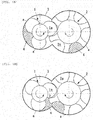
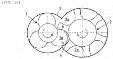
- FIG. 1A to FIG. 1C are explanatory diagrams of conventional screw rotors.
- FIG. 1A, FIG. 1B and FIG. 1C illustrate the process sequence of fluid compression.
- each of the two rotors includes a plurality of lobes or interlobes. Respective rotors have shapes twisted around rotating axes at twist angles matching with each other.
- main rotor 1 the rotor having a plurality of lobes 1a
- gate rotor 2 the rotor having a plurality of interlobes 2a
- fluid confining spaces 4 defined by the lobes 1a of the main rotor 1, the interlobes 2a of the gate rotor 2, and a casing 3 are indicated by the hatched areas.
- the cross-sectional shape of the confining space 4 changes in the order of FIG. 1A, FIG. 1B and FIG. 1C .
- the confining space 4 is squeezed in the axial direction when the sectional area formed between the main rotor 1 and the gate rotor 2 eventually becomes a minimum.
- the confining space 4 moves in the axial direction as the main rotor 1 and the gate rotor 2 rotate. As a result, a fluid is compressed as the confining space 4 is gradually narrowed.
- FIG. 2B is an explanatory diagram of a leakage path.
- the lobe tip of the main rotor 1 leaves the casing 3. Thereafter, a clearance (hereinafter referred to as "blow hole") appears among the main rotor 1, the gate rotor 2 and the casing 3 in a rotation phase until a lobe tip arc C2 of the gate rotor 2 (a gate leading-side lobe tip arc 24b, which is discussed later) comes in contact with a trailing lobe face of the main rotor 1.
- the blow hole leads to the occurrence of a leakage 5 of the compressed fluid, thus resulting in lower efficiency of the compressor.
- an object of the present disclosure is to provide a screw rotor capable of reducing a clearance (a blow hole) among a main rotor, a gate rotor and a casing to thereby reduce the leakage amount of a compressed fluid, thus permitting higher efficiency of a compressor.
- a screw rotor including a main rotor and a gate rotor each having a plurality of lobes or interlobes, and the main rotor and the gate rotor being meshed with each other and rotatable about a rotating axis of each thereof in an operating space formed by a casing, wherein
- This arrangement minimizes an area of a blow hole so that deterioration in the efficiency of a compressor can be suppressed as much as possible.
- the screw rotor described above at the specific rotation phase of the rotor, the three points of the main trailing-side lobe tip point B1, the gate leading-side lobe tip point D2', and the intersection point Q between the surface of the casing facing the main rotor and the surface of the casing facing the gate rotor coincide each other.
- a main trailing lobe face is formed by the epicycloid curve traced by the gate leading-side lobe tip point D2' in accordance with rotation phase advancement from the specific rotation phase
- a gate leading lobe face is formed by the epicycloid curve traced by the main trailing-side lobe tip point B1 in accordance with rotation phase advancement from the specific rotation phase.
- FIG. 3A, FIG. 3B and FIG. 5 are explanatory diagrams of the screw rotors in accordance with the present disclosure, illustrating a section perpendicular to the rotating axes of the screw rotors.
- FIG. 3A and FIG. 3B are the explanatory diagrams illustrating ideal lobe shapes
- FIG. 5 is the explanatory diagram illustrating practical lobe shapes.
- a screw compressor in accordance with the present disclosure includes a main rotor 10 and a gate rotor 20 meshed with the main rotor 10, the respective rotors being configured to be rotatable about parallel axes in an operating space formed (e.g., airtightly) by a casing 3.
- the two rotors each include a plurality of lobes or interlobes, and are formed in shapes twisted around the rotating axes at twist angles matching with each other.
- the rotational centers i.e. the rotating axes
- the rotational centers may be vertical or inclined.
- FIG. 3A, FIG. 3B and FIG. 5 each illustrate only one lobe of each of a main rotor lobe 10a and a gate rotor interlobe 20a.
- the main rotor 10 rotates counterclockwise, while the gate rotor 20 rotates clockwise.
- the lobe tip point of the main rotor 10 (a main leading-side lobe tip point A1) coincides with a lobe root point of the gate rotor 20 (a gate trailing-side lobe root point A2).
- the rotational angles of the two rotors at this time are defined as the reference positions, i.e. zero rotational angles.
- the front side (the upper side in the drawings) in the rotational direction of the main rotor lobe 10a is referred to as "the leading-side.”
- the lobe face (the upper side in the drawings) of the gate rotor interlobe 20a that faces the leading-side of the main rotor lobe 10a is referred to as "the trailing-side.”
- the opposite side (the lower side in the drawings) from the leading-side of the main rotor lobe 10a i.e.
- the trailing-side the opposite side (the lower side in the drawings) from the trailing-side of the gate rotor interlobe 20a, i.e. the lobe face of the gate rotor interlobe 20a that faces the trailing-side of the main rotor lobe 10a, is referred to as "the leading-side.”
- leading-side lobe face is referred to as “the leading lobe face”
- trailing-side lobe face is referred to as “the trailing lobe face.”
- the main rotor 10 includes a main pitch circle 11 and a main lobe tip circle 12.
- the gate rotor 20 includes a gate pitch circle 21, which is in contact with the main pitch circle 11 at a pitch point P, and a gate lobe bottom circle 22 in contact with the main lobe tip circle 12.
- the gate trailing-side lobe root point A2 and the gate leading-side lobe root point B2 are positioned on the gate lobe bottom circle 22.
- the pitch point P is a point obtained by internally dividing the segment, which connects the rotational center of the main rotor 10 and the rotational center of the gate rotor 20, by the ratio of the number of the teeth of the main rotor 10 (three in the example illustrated in FIG. 1A to FIG. 1C ) and the number of the teeth of the gate rotor 20 (six in the example illustrated in FIG. 1A to FIG. 1C ).
- the main pitch circle 11 is an imaginary circle, the center of which is the rotational center of the main rotor 10 and which passes through the pitch point P.
- the gate pitch circle 21 is an imaginary circle, the center of which is the rotational center of the gate rotor 20 and which passes through the pitch point P.
- a part of the inner surface of the casing 3 (refer to FIG. 1A to FIG. 1C ) that faces the main rotor 10 is formed of a circle adjacent to the main lobe tip circle 12.
- a part of the inner surface of the casing 3 that faces the gate rotor 20 is formed of a circle adjacent to the gate lobe tip circle 23.
- the main rotor 10 and the gate rotor 20 rotate, the main pitch circle 11 and the gate pitch circle 21 being synchronized with each other.
- the synchronization is effected by the contact between the lobe face of each of the main rotor lobes 10a and the lobe face of each of the gate rotor interlobes 20a. There are cases where a separate gear for synchronization is provided.
- the main rotor lobe 10a includes the main leading-side lobe tip point A1 and the main trailing-side lobe tip point B1, which are positioned on the main lobe tip circle 12.
- a main lobe outer peripheral surface (A1-B1) from the main leading-side lobe tip point A1 to the main trailing-side lobe tip point B1 forms an arc on the main lobe tip circle 12, and forms the lobe tip sealing surface "a" between itself and the inner surface of the casing 3 that encloses the main rotor 10.
- a lobe of the gate rotor 20 includes the gate leading-side lobe tip point D2' or G2 and the gate trailing-side lobe tip point C2' or F2, which are positioned on the gate lobe tip circle 23.
- the gate lobe outer peripheral surface (D2'/F2-C2'/G2) from the gate leading-side lobe tip point D2' or G2 to the gate trailing-side lobe tip point C2' or F2 forms an arc on the gate lobe tip circle 23, and forms the lobe tip sealing surface "a" between itself and the inner surface of the casing 3 that encloses the gate rotor 20.
- the gate rotor interlobe 20a forms the inter-rotor sealing line "b" between itself and the trailing lobe face of the main rotor lobe 10a, at the gate leading-side lobe tip point D2' or in the gate leading-side lobe tip arc 24b.
- the gate rotor interlobe 20a forms the inter-rotor sealing line "b" between itself and the leading lobe face of the main rotor lobe 10a, at the gate trailing-side lobe tip point C2' or in the gate trailing-side lobe tip arc 24a.
- the gate rotor interlobe 20a forms the inter-rotor sealing line "b" between itself and the trailing lobe face of the main rotor lobe 10a at the gate leading-side lobe tip point D2' or the gate leading-side lobe tip arc 24b.
- the main rotor lobe 10a further includes the main leading-side lobe root point C1', the main trailing-side lobe root point D1', and the main leading intermediate point E1.
- the main leading-side lobe root point C1' and the main trailing-side lobe root point D1' are positioned on the main pitch circle 11.
- the main leading intermediate point E1 lies between the main leading-side lobe tip point A1 and the main leading-side lobe root point C1' and is positioned at the intersection point of the main leading lobe face and the gate pitch circle 21 when the main rotor lobe 10a and the gate rotor interlobe 20a directly face each other.
- the gate rotor interlobe 20a further includes the gate trailing-side lobe tip point C2' and the gate leading-side lobe tip point D2' positioned on the gate pitch circle 21.
- the arc from the main leading-side lobe tip point A1 to the main leading intermediate point E1 and the arc from the gate trailing-side lobe root point A2 to the gate trailing-side lobe tip point C2' coincide with each other to become the same arc whose center is the pitch point P.
- the radius of the arc is the length from the pitch point P to the main leading-side lobe tip point A1 (or the gate trailing-side lobe root point A2).
- a main leading lobe face (E1-Cl') from the main leading intermediate point E1 to the main leading-side lobe root point C1' is determined as a first epicycloid curve traced by the gate trailing-side lobe tip point C2'.
- the first epicycloid curve which is traced by the trailing-side lobe tip point C2' in the rotation phase section from a rotation phase at which the gate trailing-side lobe tip point C2' coincides with the main leading-side lobe root point C1' to a rotation phase at which the gate trailing-side lobe tip point C2' coincides with the main leading intermediate point E1, is the main leading lobe face (E1-C1') from the main leading-side lobe root point C1' to the main leading intermediate point E1.
- epicycloid curve means a curve (the curve (E1-C1') in this example) in a coordinate system fixed to one rotating rotor, the curve being drawn by a point (the gate trailing-side lobe tip point C2' in this example) in a coordinate system fixed to the other rotating rotor when the main rotor 10 and the gate rotor 20 rotate in synchronization.
- the gate trailing-side lobe tip point C2' and the main leading lobe face (E1-C1') of the lobe 10a of the main rotor 10 constantly contact each other while rotating.
- an inter-rotor clearance at the inter-rotor sealing line "b" (refer to FIG. 1A to FIG. 1C ) in the part concerned can be kept slight.
- the three points namely, the main trailing-side lobe tip point B1, the gate leading-side lobe tip point D2', and the intersection point Q between the surface of the casing 3 facing the main rotor 10 and the surface of the casing 3 facing the gate rotor 20, coincide with each other.
- the main trailing lobe face (B1-D1') from the main trailing-side lobe tip point B1 to the main trailing-side lobe root point D1' is determined as a second epicycloid curve traced by the gate leading-side lobe tip point D2'.
- the gate leading-side lobe tip point D2' and the trailing lobe face (B1-D1') of the main rotor lobe 10a constantly contact each other while rotating. Thereby, an inter-rotor clearance at the inter-rotor sealing line "b" in the part concerned can be kept slight.
- the gate leading lobe face (B2-D2') from the gate leading-side lobe root point B2 to the gate leading-side lobe tip point D2' is a third epicycloid curve traced by the main trailing-side lobe tip point B1.
- the main trailing-side lobe tip point B1 and the gate leading lobe face (B2-D2') of the gate rotor interlobe 20a constantly contact each other while rotating. Thereby, an inter-rotor clearance at the inter-rotor sealing line "b" in the part concerned can be kept slight.
- a ratio L1:L2 between a distance L1 from B2 to B1 and a distance L2 from B1 to D2' may be set within the range of 2:8 to 7:3.
- the main trailing-side lobe tip point B1 contacts the gate leading lobe face in the range from B2 to D2' on the gate leading lobe face (B2-D2').
- the three points namely, the main trailing-side lobe tip point B1, the gate leading-side lobe tip point D2', and the intersection point Q of the surface of the casing 3 facing the main rotor 10 and the surface of the casing 3 facing the gate rotor 20, coincide with each other at the specific rotation phase of the rotors (this phase being referred to as "the three-point coincidence phase").
- the lobe tip of the main rotor 10 and the lobe tip of the gate rotor 20 form seals between the lobe tips and the casing 3 in the rotation phase until immediately before the three-point coincidence phase.
- the seals are continuously formed between the main trailing-side lobe tip point B1 and the leading lobe face of the gate rotor interlobe 20a and between the gate leading-side lobe tip point D2' and the trailing lobe face of the main rotor lobe 10a in the rotation phase immediately following the three-point coincidence phase.
- this arrangement closes the blow hole so that deterioration in the efficiency of the compressor attributable to the leakage of a fluid can be made insignificant.
- the phase of the trailing lobe face (B1-Dl') with respect to the leading lobe face (B2-D2') may be set such that the confining space that appears between the trailing lobe face (B1-D1') of the main rotor 10 and the leading lobe face (B2-D2') of the gate rotor 20 is minimized when the main rotor lobe 10a and the gate rotor interlobe 20a face each other.
- the lobe 10a of the main rotor 10 is modified by the following (1) to (4) on the basis of the ideal lobe shape illustrated in FIG. 3A and FIG. 3B .
- the distance r 1 is equal to the radius r 1 of the main leading-side lobe root arc 14a and the radius r 1 of the main trailing-side lobe root arc 14b, and also equal to the radius difference ⁇ r 1 of the main lobe bottom circle 13 and the radius difference ⁇ r 1 of the main lobe tip circle 12.
- Each of the distance, the radius and the radius difference with the reference sign r 1 takes a value that is, for example, larger than 0% of the distance between the rotating axis of the main rotor 10 and the rotating axis of the gate rotor 20 and 20% or less of the distance between the rotating axis of the main rotor 10 and the rotating axis of the gate rotor 20.
- interlobe 20a of the gate rotor 20 is modified by the following (5) to (8) on the basis of the ideal lobe shape illustrated in FIG. 3A and FIG. 3B .
- the distance r 2 may be equal to the radius r 2 of the gate trailing-side lobe tip arc 24a and the radius r 2 of the gate leading-side lobe tip arc 24b, and also equal to the radius difference ⁇ r 2 of the gate lobe bottom circle 22 and the radius difference ⁇ r 2 of the gate lobe tip circle 23.
- Each of the distance, the radius and the radius difference with the reference sign r 2 takes a value that is, for example, larger than 0% of the distance between the rotating axis of the main rotor 10 and the rotating axis of the gate rotor 20 and 20% or less of the distance between the rotating axis of the main rotor 10 and the rotating axis of the gate rotor 20.
- the main rotor lobe 10a is created according to the foregoing procedure (the foregoing modification) on the basis of the lobe shape illustrated in FIG. 3A and FIG. 3B .
- the radius of the main lobe bottom circle 13 is smaller than that of the main pitch circle 11 by the radius difference ⁇ r 1 .
- the points of the leading lobe face and the trailing lobe face on the main pitch circle 11 are connected to the main lobe bottom circle 13 by the main leading-side lobe root arc 14a and the main trailing-side lobe root arc 14b.
- the gate rotor interlobe 20a is created according to the foregoing procedure (the foregoing modification) on the basis of the lobe shape illustrated in FIG. 3A and FIG. 3B .
- the radius of the gate lobe tip circle 23 is larger than that of the gate pitch circle 21 by the radius difference ⁇ r 2 .
- the points of the leading lobe face and the trailing lobe face on the gate pitch circle 21 are connected to the gate lobe tip circle 23 by the gate trailing-side lobe tip arc 24a and the gate leading-side lobe tip arc 24b.
- a ratio La:Lb between a distance La from B2 to B1 and a distance Lb from B1 to G2 may be set within the range of 1:9 to 6:4.
- the main trailing-side lobe tip point B1 contacts the gate leading lobe face in the range from B2 to G2 on the gate leading lobe face (B2-G2).
- the radius difference ⁇ r 1 of the main lobe bottom circle 13 of the main rotor 10 and the radii r 1 of the main leading-side lobe root arc 14a and the main trailing-side lobe root arc 14b may be set to be larger than the other radius difference ⁇ r 2 and the radius r 2 (i.e. the radius difference ⁇ r 2 of the gate lobe tip circle 23 and the radii r 2 of the gate trailing-side lobe tip arc 24a and the gate leading-side lobe tip arc 24b).
- the radius difference ⁇ r 1 of the main lobe bottom circle 13 of the main rotor 10 and the radii r 1 of the main leading-side lobe root arc 14a and the main trailing-side lobe root arc 14b are set such that the main rotor lobe 10a is offset (shifted) to a side on which the main rotor lobe 10a is diminished or to a side on which the gate rotor interlobe 20a is enlarged, by a width that is adequate for avoiding the mutual interference between the lobe face of the main rotor lobe 10a and the lobe face of the gate rotor interlobe 20a.
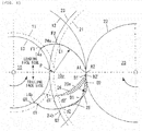
- FIG. 4 is an explanatory diagram illustrating the method for reducing the confining space.
- the phase of the trailing lobe face with respect to the leading lobe face is set such that the confining space that appears between the trailing lobe face of the main rotor 10 and the leading lobe face of the gate rotor 20 is minimized when the main rotor lobe 10a and the gate rotor interlobe 20a directly face each other.
- the flow passage area of the leakage of a fluid at the part concerned is minimized so that deterioration in the efficiency of the compressor can be suppressed.
- FIG. 4 illustrates the main rotor lobe 10a and the gate rotor interlobe 20a directly facing each other.
- the arc between the two sealing lines "b" illustrated in FIG. 1C corresponds to the arc between E1 and d2 in FIG. 4 .
- the leading lobe face of the main rotor 10 and the trailing lobe face of the gate rotor 20 coincide with each other in the range of A1 to E1, and there would be no clearance in an ideal case.
- B1' denotes a main trailing-side lobe tip point when the main trailing-side lobe tip point is set at a phase (position) relatively close to the main leading-side lobe tip point A1.
- d1' and d2' denote a main trailing-side lobe root point and a gate leading-side lobe tip point, respectively, when the main trailing-side lobe tip point B1' is set.
- reference sign 26 denotes the confining space when the main trailing-side lobe tip point B1' is set.
- A1 denotes a main leading-side lobe tip point common to both of the case where the main trailing-side lobe tip point is set at B1' and the case where the main trailing-side lobe tip point is set at B1.
- A2 denotes a gate trailing-side lobe root point that lies at the same phase in the foregoing both cases.
- FIG. 4 illustrates the relative positions of the lobe tip circle and the trailing lobe face (A1-d1') of the main rotor 10 and the lobe bottom circle and the leading lobe face (A2-d2') of the gate rotor 20 in the confining space 26 between the trailing lobe face of the main rotor 10 and the leading lobe face of the gate rotor 20 when the main leading-side lobe tip point A1 and the main trailing-side lobe tip point B1' are at relatively close phases.
- the relative positions thereof also change, as indicated by the lobe tip circle and the trailing lobe face (A1-d1) of the main rotor 10 and the lobe bottom circle and the leading lobe face (A2-d2) of the interlobe 20a.
- the area of a confining space 25 that appears along A1-B1-d2 is smaller than the area of the confining space 26 that appears along A1-B1'-d2'.
- phase of the trailing lobe face with respect to the leading lobe face is set such that the confining space 25 enclosed by the curve (A1-d1) and the curve (A2-d2) is minimized.
- the deterioration in the efficiency of the compressor can be suppressed by minimization of the clearance between the main rotor 10 and the gate rotor 20 in the phase at which the main rotor lobe 10a and the gate rotor interlobe 20a directly face each other.
- the screw rotor according to the foregoing embodiment may be described by any one of the following configurations 1 to 4.
- a screw rotor includes a main rotor and a gate rotor each having a plurality of lobes or interlobes, and the main rotor and the gate rotor being meshed with each other and rotatable about a rotating axis of each thereof in an operating space formed by a casing, wherein
- FIG. 2A is the explanatory diagram of a leakage path that is different from the one illustrated in FIG. 2B .
- a clearance to the adjacent space, the volume of which increases, is left between the main rotor 1 and the gate rotor 2. The clearance leads to the leakage of a compressed fluid, resulting in deteriorated efficiency of a compressor.
- the following configuration 2 may be adopted to implement a screw rotor capable of reducing the clearance that appears when the main rotor lobe and the gate rotor interlobe directly face each other, thereby reducing the leakage volume of a compressed fluid with resultant higher efficiency of the compressor.
- a phase of a trailing lobe face of the main rotor with respect to a leading lobe face of the gate rotor is set such that a confining space that appears between the trailing lobe face and the leading lobe face is minimized when the main rotor lobe and the gate rotor interlobe directly face each other.
- the leading lobe face and the trailing lobe face of the main rotor lobe are offset inward by a distance r 1
- the main lobe bottom circle is set to be smaller than the main pitch circle by a radius difference ⁇ r 1
- the main lobe tip circle is made smaller by the radius difference ⁇ r 1
- the leading lobe face and the trailing lobe face are connected to the main lobe bottom circle by a main leading-side lobe root arc that has a radius r 1 and whose center is the main leading-side lobe root point C1' and a main trailing-side lobe root arc that has the radius r 1 and whose center is the main trailing-side lobe root point D1' as the center thereof
- the leading lobe face and the trailing lobe face of the gate rotor interlobe are offset outward by a distance r 2
- the gate lobe bottom circle is set to be larger
- the radius difference ⁇ r 1 of the main lobe bottom circle of the main rotor and the radii r 1 of the main leading-side lobe root arc and the main trailing-side lobe root arc are set to be larger than the radius difference ⁇ r 2 and the radius r 2 , and the lobe face of the main rotor lobe or the gate rotor interlobe is offset to a side on which the main rotor lobe is diminished or to a side on which the gate rotor interlobe is enlarged, by an adequate width for avoiding the interference between the lobe face of the main rotor lobe and the lobe face of the gate rotor interlobe.
- the interference can be suppressed when the distance between the two rotor axes fluctuate.
Landscapes
- Engineering & Computer Science (AREA)
- Mechanical Engineering (AREA)
- General Engineering & Computer Science (AREA)
- Applications Or Details Of Rotary Compressors (AREA)
Abstract
Description
- Embodiments described herein relate to a screw rotor used in a screw compressor.
- A screw compressor includes two screw rotors provided with helical grooves (interlobes) in the outer peripheries thereof, and a casing that contains the two screw rotors. The two rotors mesh with each other and rotate in synchronization.
- The screw compressor is a device that rotates the rotors to thereby narrow the space between the casing and the rotors to compress a fluid confined between the casing and the rotors.
- The lobe shapes of such screw rotors are described in, for example,
PTLs 1 to 5. -
- PTL 1: Japanese Patent Publication Laid-open No.
2007-146659 - PTL 2: Japanese Patent Publication Laid-open No.
2009-243325 - PTL 3: Japanese Patent Publication Laid-open No.
2001-227485 - PTL 4: Japanese Patent Publication Laid-open No.
2000-154792 - PTL 5: Japanese Patent Publication Laid-open No.
9-100788 -
FIG. 1A to FIG. 1C are explanatory diagrams of conventional screw rotors.FIG. 1A, FIG. 1B andFIG. 1C illustrate the process sequence of fluid compression. - Referring to
FIG. 1A, FIG. 1B andFIG. 1C , each of the two rotors includes a plurality of lobes or interlobes. Respective rotors have shapes twisted around rotating axes at twist angles matching with each other. - Hereinafter, in the present disclosure, of the two rotors, the rotor having a plurality of
lobes 1a is referred to as "main rotor 1," and the rotor having a plurality ofinterlobes 2a is referred to as "gate rotor 2." - In
FIG. 1A, FIG. 1B andFIG. 1C , fluidconfining spaces 4 defined by thelobes 1a of themain rotor 1, theinterlobes 2a of thegate rotor 2, and acasing 3 are indicated by the hatched areas. The cross-sectional shape of theconfining space 4 changes in the order ofFIG. 1A, FIG. 1B andFIG. 1C . Theconfining space 4 is squeezed in the axial direction when the sectional area formed between themain rotor 1 and thegate rotor 2 eventually becomes a minimum. - The
confining space 4 moves in the axial direction as themain rotor 1 and thegate rotor 2 rotate. As a result, a fluid is compressed as theconfining space 4 is gradually narrowed. - The positions at which the compressed fluid leaks are indicated by lobe tip sealing surfaces "a" between the
main rotor 1 and thecasing 3 and between thegate rotor 2 and thecasing 3 inFIG. 1A , by the lobe tip sealing surfaces "a" and an inter-rotor sealing line "b" inFIG. 1B , and by the inter-rotor sealing lines "b" inFIG. 1C . -
FIG. 2B is an explanatory diagram of a leakage path. - As illustrated in
FIG. 2B , the lobe tip of the main rotor 1 (a main trailing-side lobe tip point B1, which is discussed later) leaves thecasing 3. Thereafter, a clearance (hereinafter referred to as "blow hole") appears among themain rotor 1, thegate rotor 2 and thecasing 3 in a rotation phase until a lobe tip arc C2 of the gate rotor 2 (a gate leading-sidelobe tip arc 24b, which is discussed later) comes in contact with a trailing lobe face of themain rotor 1. The blow hole leads to the occurrence of aleakage 5 of the compressed fluid, thus resulting in lower efficiency of the compressor. - The present disclosure has been made to solve the problem described above. More specifically, an object of the present disclosure is to provide a screw rotor capable of reducing a clearance (a blow hole) among a main rotor, a gate rotor and a casing to thereby reduce the leakage amount of a compressed fluid, thus permitting higher efficiency of a compressor.
- To attain this object, there is provided a screw rotor including a main rotor and a gate rotor each having a plurality of lobes or interlobes, and the main rotor and the gate rotor being meshed with each other and rotatable about a rotating axis of each thereof in an operating space formed by a casing, wherein
- (A) in a section perpendicular to the rotating axis,
the main rotor includes a main pitch circle and a main lobe tip circle, and
the gate rotor includes a gate pitch circle that contacts the main pitch circle at a pitch point P, and a gate lobe bottom circle that contacts the main lobe tip circle, - (B) each of the main rotor lobes includes:
- a main leading-side lobe tip point A1 and a main trailing-side lobe tip point B1, which are positioned on the main lobe tip circle,
- a main leading-side lobe root point C1' and a main trailing-side lobe root point D1', which are positioned on the main pitch circle, and
- a main leading intermediate point E1 which lies between the main leading-side lobe tip point A1 and the main leading-side lobe root point C1' and which is positioned at the intersection point of a leading lobe face of the main rotor lobe and the gate pitch circle when the main rotor lobe and the gate rotor interlobe directly face each other,
- (C) each of the gate rotor interlobes includes:
- a gate trailing-side lobe root point A2 and a gate leading-side lobe root point B2, which are positioned on the gate lobe bottom circle, and
- a gate trailing-side lobe tip point C2' and a gate leading-side lobe tip point D2', which are positioned on the gate pitch circle,
- (D) when the main rotor lobe and the gate rotor interlobe directly face each other, a curve from the main leading-side lobe tip point A1 to the main leading intermediate point E1 and a curve from the gate trailing-side lobe root point A2 to the gate trailing-side lobe tip point C2' coincide with each other to become the same arc whose center is the pitch point P, and
a curve from the main leading intermediate point E1 to the main leading-side lobe root point C1' of the main rotor is a first epicycloid curve traced by the gate trailing-side lobe tip point C2' of the gate rotor, and - (E) at a specific rotation phase of the screw rotor, three points of the main trailing-side lobe tip point B1, the gate leading-side lobe tip point D2', and an intersection point Q between a surface of the casing facing the main rotor and a surface of the casing facing the gate rotor coincide with each other, a curve from the main trailing-side lobe tip point B1 to the main trailing-side lobe root point D1' is a second epicycloid curve traced by the gate leading-side lobe tip point D2' in accordance with rotation phase advancement from the specific rotation phase, and a curve from the gate leading-side lobe root point B2 to the gate leading-side lobe tip point D2' is a third epicycloid curve traced by the main trailing-side lobe tip point B1 in accordance with rotation phase advancement from the specific rotation phase.
- This arrangement minimizes an area of a blow hole so that deterioration in the efficiency of a compressor can be suppressed as much as possible.
- According to the screw rotor described above, at the specific rotation phase of the rotor, the three points of the main trailing-side lobe tip point B1, the gate leading-side lobe tip point D2', and the intersection point Q between the surface of the casing facing the main rotor and the surface of the casing facing the gate rotor coincide each other. A main trailing lobe face is formed by the epicycloid curve traced by the gate leading-side lobe tip point D2' in accordance with rotation phase advancement from the specific rotation phase, and a gate leading lobe face is formed by the epicycloid curve traced by the main trailing-side lobe tip point B1 in accordance with rotation phase advancement from the specific rotation phase. Thereby, the blow hole is ideally closed so that deterioration in the efficiency of the compressor attributable to the leakage of a fluid from the part concerned can be made slight.
-
-
FIG. 1A is an explanatory diagram of a conventional screw rotor; -
FIG. 1B is another explanatory diagram of the conventional screw rotor; -
FIG. 1C is yet another explanatory diagram of the conventional screw rotor; -
FIG. 2A is an explanatory diagram of a first leakage path; -
FIG. 2B is an explanatory diagram of a second leakage path; -
FIG. 3A is an explanatory diagram of an ideal lobe shapes in accordance with the present disclosure; -
FIG. 3B is another explanatory diagram of the ideal lobe shapes in accordance with the present disclosure; -
FIG. 4 is an explanatory diagram illustrating a method for reducing a confining space in accordance with the present disclosure; and -
FIG. 5 is an explanatory diagram of practical lobe shapes in accordance with the present disclosure. - The following describes in detail an embodiment of the present disclosure with reference to the accompanying drawings. The same elements in the drawings are assigned the same reference signs, and the same description is not repeated.
-
FIG. 3A, FIG. 3B andFIG. 5 are explanatory diagrams of the screw rotors in accordance with the present disclosure, illustrating a section perpendicular to the rotating axes of the screw rotors. Among the diagrams,FIG. 3A and FIG. 3B are the explanatory diagrams illustrating ideal lobe shapes, andFIG. 5 is the explanatory diagram illustrating practical lobe shapes. - A screw compressor in accordance with the present disclosure includes a
main rotor 10 and agate rotor 20 meshed with themain rotor 10, the respective rotors being configured to be rotatable about parallel axes in an operating space formed (e.g., airtightly) by acasing 3. - The two rotors (namely, the
main rotor 10 and the gate rotor 20) each include a plurality of lobes or interlobes, and are formed in shapes twisted around the rotating axes at twist angles matching with each other. - For the convenience of explanation, it is hereinafter assumed that the rotational centers (i.e. the rotating axes) of the
main rotor 10 and thegate rotor 20 are parallel to each other and horizontal. However, the present disclosure is not limited thereto, and the rotational centers may be vertical or inclined. -
FIG. 3A, FIG. 3B andFIG. 5 each illustrate only one lobe of each of amain rotor lobe 10a and agate rotor interlobe 20a. In this example, themain rotor 10 rotates counterclockwise, while thegate rotor 20 rotates clockwise. When themain rotor lobe 10a and thegate rotor interlobe 20a directly face each other, the lobe tip point of the main rotor 10 (a main leading-side lobe tip point A1) coincides with a lobe root point of the gate rotor 20 (a gate trailing-side lobe root point A2). The rotational angles of the two rotors at this time are defined as the reference positions, i.e. zero rotational angles. - Hereinafter, in the present disclosure, the front side (the upper side in the drawings) in the rotational direction of the
main rotor lobe 10a is referred to as "the leading-side." In the present disclosure, the lobe face (the upper side in the drawings) of thegate rotor interlobe 20a that faces the leading-side of themain rotor lobe 10a is referred to as "the trailing-side." In the present disclosure, the opposite side (the lower side in the drawings) from the leading-side of themain rotor lobe 10a, i.e. the rear side in the rotational direction of themain rotor lobe 10a, is referred to as "the trailing-side." In the present disclosure, the opposite side (the lower side in the drawings) from the trailing-side of thegate rotor interlobe 20a, i.e. the lobe face of thegate rotor interlobe 20a that faces the trailing-side of themain rotor lobe 10a, is referred to as "the leading-side." - Further, the leading-side lobe face is referred to as "the leading lobe face," and the trailing-side lobe face is referred to as "the trailing lobe face."
- Referring to
FIG. 3A, FIG. 3B andFIG. 5 , themain rotor 10 includes amain pitch circle 11 and a mainlobe tip circle 12. Further, thegate rotor 20 includes agate pitch circle 21, which is in contact with themain pitch circle 11 at a pitch point P, and a gate lobebottom circle 22 in contact with the mainlobe tip circle 12. - The gate trailing-side lobe root point A2 and the gate leading-side lobe root point B2 are positioned on the gate lobe
bottom circle 22. - The pitch point P is a point obtained by internally dividing the segment, which connects the rotational center of the
main rotor 10 and the rotational center of thegate rotor 20, by the ratio of the number of the teeth of the main rotor 10 (three in the example illustrated inFIG. 1A to FIG. 1C ) and the number of the teeth of the gate rotor 20 (six in the example illustrated inFIG. 1A to FIG. 1C ). - The
main pitch circle 11 is an imaginary circle, the center of which is the rotational center of themain rotor 10 and which passes through the pitch point P. Further, thegate pitch circle 21 is an imaginary circle, the center of which is the rotational center of thegate rotor 20 and which passes through the pitch point P. - A part of the inner surface of the casing 3 (refer to
FIG. 1A to FIG. 1C ) that faces themain rotor 10 is formed of a circle adjacent to the mainlobe tip circle 12. Similarly, a part of the inner surface of thecasing 3 that faces thegate rotor 20 is formed of a circle adjacent to the gatelobe tip circle 23. - The
main rotor 10 and thegate rotor 20 rotate, themain pitch circle 11 and thegate pitch circle 21 being synchronized with each other. The synchronization is effected by the contact between the lobe face of each of themain rotor lobes 10a and the lobe face of each of thegate rotor interlobes 20a. There are cases where a separate gear for synchronization is provided. - Referring to
FIG. 1A ,FIG. 3A ,FIG. 3B andFIG. 5 , themain rotor lobe 10a includes the main leading-side lobe tip point A1 and the main trailing-side lobe tip point B1, which are positioned on the mainlobe tip circle 12. A main lobe outer peripheral surface (A1-B1) from the main leading-side lobe tip point A1 to the main trailing-side lobe tip point B1 forms an arc on the mainlobe tip circle 12, and forms the lobe tip sealing surface "a" between itself and the inner surface of thecasing 3 that encloses themain rotor 10. - A lobe of the
gate rotor 20 includes the gate leading-side lobe tip point D2' or G2 and the gate trailing-side lobe tip point C2' or F2, which are positioned on the gatelobe tip circle 23. The gate lobe outer peripheral surface (D2'/F2-C2'/G2) from the gate leading-side lobe tip point D2' or G2 to the gate trailing-side lobe tip point C2' or F2 forms an arc on the gatelobe tip circle 23, and forms the lobe tip sealing surface "a" between itself and the inner surface of thecasing 3 that encloses thegate rotor 20. - Referring to
FIG. 1B ,FIG. 3A ,FIG. 3B andFIG. 5 , in addition to the above, thegate rotor interlobe 20a forms the inter-rotor sealing line "b" between itself and the trailing lobe face of themain rotor lobe 10a, at the gate leading-side lobe tip point D2' or in the gate leading-sidelobe tip arc 24b. - Referring to
FIG. 1C ,FIG. 3A ,FIG. 3B andFIG. 5 , thegate rotor interlobe 20a forms the inter-rotor sealing line "b" between itself and the leading lobe face of themain rotor lobe 10a, at the gate trailing-side lobe tip point C2' or in the gate trailing-sidelobe tip arc 24a. In addition, thegate rotor interlobe 20a forms the inter-rotor sealing line "b" between itself and the trailing lobe face of themain rotor lobe 10a at the gate leading-side lobe tip point D2' or the gate leading-sidelobe tip arc 24b. - The description given above is the same among
FIG. 3A, FIG. 3B andFIG. 5 . - An ideal lobe shape is described first in the following, with reference to
FIG. 3A and FIG. 3B . - The
main rotor lobe 10a further includes the main leading-side lobe root point C1', the main trailing-side lobe root point D1', and the main leading intermediate point E1. The main leading-side lobe root point C1' and the main trailing-side lobe root point D1' are positioned on themain pitch circle 11. The main leading intermediate point E1 lies between the main leading-side lobe tip point A1 and the main leading-side lobe root point C1' and is positioned at the intersection point of the main leading lobe face and thegate pitch circle 21 when themain rotor lobe 10a and thegate rotor interlobe 20a directly face each other. - The
gate rotor interlobe 20a further includes the gate trailing-side lobe tip point C2' and the gate leading-side lobe tip point D2' positioned on thegate pitch circle 21. - When the
main rotor lobe 10a and thegate rotor interlobe 20a directly face each other, the arc from the main leading-side lobe tip point A1 to the main leading intermediate point E1 and the arc from the gate trailing-side lobe root point A2 to the gate trailing-side lobe tip point C2' coincide with each other to become the same arc whose center is the pitch point P. The radius of the arc is the length from the pitch point P to the main leading-side lobe tip point A1 (or the gate trailing-side lobe root point A2). - Therefore, when the
main rotor lobe 10a and thegate rotor interlobe 20a illustrated inFIG. 3A directly face each other, the main leading lobe face (A1-E1) and the gate trailing lobe face (A2-C2') coincide with each other, thus eliminating the clearance between the leading face of thelobe 10a of themain rotor 10 and the trailing face of theinterlobe 20a of thegate rotor 20. - Referring to
FIG. 3A , a main leading lobe face (E1-Cl') from the main leading intermediate point E1 to the main leading-side lobe root point C1' is determined as a first epicycloid curve traced by the gate trailing-side lobe tip point C2'. More specifically, the first epicycloid curve, which is traced by the trailing-side lobe tip point C2' in the rotation phase section from a rotation phase at which the gate trailing-side lobe tip point C2' coincides with the main leading-side lobe root point C1' to a rotation phase at which the gate trailing-side lobe tip point C2' coincides with the main leading intermediate point E1, is the main leading lobe face (E1-C1') from the main leading-side lobe root point C1' to the main leading intermediate point E1. - The term "epicycloid curve" means a curve (the curve (E1-C1') in this example) in a coordinate system fixed to one rotating rotor, the curve being drawn by a point (the gate trailing-side lobe tip point C2' in this example) in a coordinate system fixed to the other rotating rotor when the
main rotor 10 and thegate rotor 20 rotate in synchronization. - Accordingly, within the range of the rotation phase concerned, the gate trailing-side lobe tip point C2' and the main leading lobe face (E1-C1') of the
lobe 10a of themain rotor 10 constantly contact each other while rotating. Thereby, an inter-rotor clearance at the inter-rotor sealing line "b" (refer toFIG. 1A to FIG. 1C ) in the part concerned can be kept slight. - As illustrated in
FIG. 3B , at a specific rotation phase of the rotors, the three points, namely, the main trailing-side lobe tip point B1, the gate leading-side lobe tip point D2', and the intersection point Q between the surface of thecasing 3 facing themain rotor 10 and the surface of thecasing 3 facing thegate rotor 20, coincide with each other. From this phase, as the rotation proceeds, the main trailing lobe face (B1-D1') from the main trailing-side lobe tip point B1 to the main trailing-side lobe root point D1' is determined as a second epicycloid curve traced by the gate leading-side lobe tip point D2'. - Therefore, within the range of the rotation phase, the gate leading-side lobe tip point D2' and the trailing lobe face (B1-D1') of the
main rotor lobe 10a constantly contact each other while rotating. Thereby, an inter-rotor clearance at the inter-rotor sealing line "b" in the part concerned can be kept slight. - Similarly, the gate leading lobe face (B2-D2') from the gate leading-side lobe root point B2 to the gate leading-side lobe tip point D2' is a third epicycloid curve traced by the main trailing-side lobe tip point B1.
- Therefore, within the range of the rotation phase, the main trailing-side lobe tip point B1 and the gate leading lobe face (B2-D2') of the
gate rotor interlobe 20a constantly contact each other while rotating. Thereby, an inter-rotor clearance at the inter-rotor sealing line "b" in the part concerned can be kept slight. InFIG. 3A , on the gate leading lobe face (B2-D2'), a ratio L1:L2 between a distance L1 from B2 to B1 and a distance L2 from B1 to D2' may be set within the range of 2:8 to 7:3. The main trailing-side lobe tip point B1 contacts the gate leading lobe face in the range from B2 to D2' on the gate leading lobe face (B2-D2'). - In the screw rotor having the foregoing ideal lobe shape, the three points, namely, the main trailing-side lobe tip point B1, the gate leading-side lobe tip point D2', and the intersection point Q of the surface of the
casing 3 facing themain rotor 10 and the surface of thecasing 3 facing thegate rotor 20, coincide with each other at the specific rotation phase of the rotors (this phase being referred to as "the three-point coincidence phase"). Hence, in the screw rotor having the ideal lobe shape, the lobe tip of themain rotor 10 and the lobe tip of thegate rotor 20 form seals between the lobe tips and thecasing 3 in the rotation phase until immediately before the three-point coincidence phase. In the screw rotor having the ideal lobe shape, the seals are continuously formed between the main trailing-side lobe tip point B1 and the leading lobe face of thegate rotor interlobe 20a and between the gate leading-side lobe tip point D2' and the trailing lobe face of themain rotor lobe 10a in the rotation phase immediately following the three-point coincidence phase. Ideally, this arrangement closes the blow hole so that deterioration in the efficiency of the compressor attributable to the leakage of a fluid can be made insignificant. - Further, in the screw rotor having the ideal lobe shape, in
FIG. 3A , the phase of the trailing lobe face (B1-Dl') with respect to the leading lobe face (B2-D2') may be set such that the confining space that appears between the trailing lobe face (B1-D1') of themain rotor 10 and the leading lobe face (B2-D2') of thegate rotor 20 is minimized when themain rotor lobe 10a and thegate rotor interlobe 20a face each other. - Next description is given of the practical lobe shape in
FIG. 5 . - The
lobe 10a of themain rotor 10 is modified by the following (1) to (4) on the basis of the ideal lobe shape illustrated inFIG. 3A and FIG. 3B . - (1) The leading lobe face and the trailing lobe face are offset inward by a distance r1.
- (2) The main lobe
bottom circle 13 is set to be smaller than themain pitch circle 11 by a radius difference Δr1. - (3) The main
lobe tip circle 12 is made smaller by the radius difference Δr1. - (4) The leading lobe face and the trailing lobe face are connected to the main lobe
bottom circle 13 by a main leading-sidelobe root arc 14a that has the radius r1 and whose center is the main leading-side lobe root point C1' and a main trailing-sidelobe root arc 14b that has the radius r1 and whose center is the main trailing-side lobe root point D1'. - The distance r1 is equal to the radius r1 of the main leading-side
lobe root arc 14a and the radius r1 of the main trailing-sidelobe root arc 14b, and also equal to the radius difference Δr1 of the main lobebottom circle 13 and the radius difference Δr1 of the mainlobe tip circle 12. Each of the distance, the radius and the radius difference with the reference sign r1 takes a value that is, for example, larger than 0% of the distance between the rotating axis of themain rotor 10 and the rotating axis of thegate rotor main rotor 10 and the rotating axis of thegate rotor 20. - Further, the
interlobe 20a of thegate rotor 20 is modified by the following (5) to (8) on the basis of the ideal lobe shape illustrated inFIG. 3A and FIG. 3B . - (5) The leading lobe face and the trailing lobe face are offset outward by a distance r2.
- (6) The gate lobe
bottom circle 22 is set to be larger by a radius difference Δr2. - (7) The gate
lobe tip circle 23 is set to be larger than thegate pitch circle 21 by the radius difference Δr2. - (8) The leading lobe face and the trailing lobe face are connected to the gate
lobe tip circle 23 by a gate trailing-sidelobe tip arc 24a that has the radius r2 and whose center is the gate trailing-side lobe tip point C2' and a gate leading-sidelobe tip arc 24b that has the radius r2 and whose center is the gate leading-side lobe tip point D2'. - The distance r2 may be equal to the radius r2 of the gate trailing-side
lobe tip arc 24a and the radius r2 of the gate leading-sidelobe tip arc 24b, and also equal to the radius difference Δr2 of the gate lobebottom circle 22 and the radius difference Δr2 of the gatelobe tip circle 23. Each of the distance, the radius and the radius difference with the reference sign r2 takes a value that is, for example, larger than 0% of the distance between the rotating axis of themain rotor 10 and the rotating axis of thegate rotor main rotor 10 and the rotating axis of thegate rotor 20. - Referring to
FIG. 5 , themain rotor lobe 10a is created according to the foregoing procedure (the foregoing modification) on the basis of the lobe shape illustrated inFIG. 3A and FIG. 3B . Here, the radius of the main lobebottom circle 13 is smaller than that of themain pitch circle 11 by the radius difference Δr1. Further, the points of the leading lobe face and the trailing lobe face on themain pitch circle 11 are connected to the main lobebottom circle 13 by the main leading-sidelobe root arc 14a and the main trailing-sidelobe root arc 14b. - Similarly, the
gate rotor interlobe 20a is created according to the foregoing procedure (the foregoing modification) on the basis of the lobe shape illustrated inFIG. 3A and FIG. 3B . Here, the radius of the gatelobe tip circle 23 is larger than that of thegate pitch circle 21 by the radius difference Δr2. Further, the points of the leading lobe face and the trailing lobe face on thegate pitch circle 21 are connected to the gatelobe tip circle 23 by the gate trailing-sidelobe tip arc 24a and the gate leading-sidelobe tip arc 24b. - With this arrangement, the contact with the
main rotor 10 at the gate rotor lobe tip is changed from the edge contact to the arc surface contact to thereby reduce the contact surface pressure at the seal part, so that the wear on the inter-rotor sealing line can be reduced. InFIG. 5 , on the gate leading lobe face (B2-G2), a ratio La:Lb between a distance La from B2 to B1 and a distance Lb from B1 to G2 may be set within the range of 1:9 to 6:4. The main trailing-side lobe tip point B1 contacts the gate leading lobe face in the range from B2 to G2 on the gate leading lobe face (B2-G2). - In addition to the characteristics of the foregoing screw rotor, the radius difference Δr1 of the main lobe
bottom circle 13 of themain rotor 10 and the radii r1 of the main leading-sidelobe root arc 14a and the main trailing-sidelobe root arc 14b may be set to be larger than the other radius difference Δr2 and the radius r2 (i.e. the radius difference Δr2 of the gatelobe tip circle 23 and the radii r2 of the gate trailing-sidelobe tip arc 24a and the gate leading-sidelobe tip arc 24b). In other words, the radius difference Δr1 of the main lobebottom circle 13 of themain rotor 10 and the radii r1 of the main leading-sidelobe root arc 14a and the main trailing-sidelobe root arc 14b are set such that themain rotor lobe 10a is offset (shifted) to a side on which themain rotor lobe 10a is diminished or to a side on which thegate rotor interlobe 20a is enlarged, by a width that is adequate for avoiding the mutual interference between the lobe face of themain rotor lobe 10a and the lobe face of thegate rotor interlobe 20a. - With this arrangement, the interference can be suppressed when the distance between the two rotor axes varies.
-
FIG. 4 is an explanatory diagram illustrating the method for reducing the confining space.
In addition to the characteristics of the screw rotor described above, inFIG. 4 , the phase of the trailing lobe face with respect to the leading lobe face is set such that the confining space that appears between the trailing lobe face of themain rotor 10 and the leading lobe face of thegate rotor 20 is minimized when themain rotor lobe 10a and thegate rotor interlobe 20a directly face each other. Thereby, the flow passage area of the leakage of a fluid at the part concerned is minimized so that deterioration in the efficiency of the compressor can be suppressed. -
FIG. 4 illustrates themain rotor lobe 10a and thegate rotor interlobe 20a directly facing each other. - The arc between the two sealing lines "b" illustrated in
FIG. 1C corresponds to the arc between E1 and d2 inFIG. 4 . At this time, the leading lobe face of themain rotor 10 and the trailing lobe face of thegate rotor 20 coincide with each other in the range of A1 to E1, and there would be no clearance in an ideal case. - In
FIG. 4 , B1' denotes a main trailing-side lobe tip point when the main trailing-side lobe tip point is set at a phase (position) relatively close to the main leading-side lobe tip point A1. InFIG. 4 , d1' and d2' denote a main trailing-side lobe root point and a gate leading-side lobe tip point, respectively, when the main trailing-side lobe tip point B1' is set. Further, inFIG. 4 ,reference sign 26 denotes the confining space when the main trailing-side lobe tip point B1' is set. InFIG. 4 , A1 denotes a main leading-side lobe tip point common to both of the case where the main trailing-side lobe tip point is set at B1' and the case where the main trailing-side lobe tip point is set at B1. InFIG. 4 , A2 denotes a gate trailing-side lobe root point that lies at the same phase in the foregoing both cases. -
FIG. 4 illustrates the relative positions of the lobe tip circle and the trailing lobe face (A1-d1') of themain rotor 10 and the lobe bottom circle and the leading lobe face (A2-d2') of thegate rotor 20 in the confiningspace 26 between the trailing lobe face of themain rotor 10 and the leading lobe face of thegate rotor 20 when the main leading-side lobe tip point A1 and the main trailing-side lobe tip point B1' are at relatively close phases. When the shape is changed from this state in a direction in which the phase difference between the leading lobe face and the trailing lobe face increases (such that the phases of the main leading-side lobe tip point A1 and the main trailing-side lobe tip point B1' are set farther away from each other), the relative positions thereof also change, as indicated by the lobe tip circle and the trailing lobe face (A1-d1) of themain rotor 10 and the lobe bottom circle and the leading lobe face (A2-d2) of theinterlobe 20a. - In this example, the area of a confining
space 25 that appears along A1-B1-d2 is smaller than the area of the confiningspace 26 that appears along A1-B1'-d2'. This means that the confining space that appears between the trailing lobe face of themain rotor 10 and the trailing lobe face of thegate rotor 20 is changed by changing the phase of the trailing lobe face with respect to the leading lobe face, and the area of the confiningspace 25 can be minimized by setting the phase to an optimum phase. - Thus, the phase of the trailing lobe face with respect to the leading lobe face is set such that the confining
space 25 enclosed by the curve (A1-d1) and the curve (A2-d2) is minimized. - With this arrangement, the deterioration in the efficiency of the compressor can be suppressed by minimization of the clearance between the
main rotor 10 and thegate rotor 20 in the phase at which themain rotor lobe 10a and thegate rotor interlobe 20a directly face each other. - The screw rotor according to the foregoing embodiment may be described by any one of the following
configurations 1 to 4. - A screw rotor includes a main rotor and a gate rotor each having a plurality of lobes or interlobes, and the main rotor and the gate rotor being meshed with each other and rotatable about a rotating axis of each thereof in an operating space formed by a casing, wherein
- (A) in a section perpendicular to the rotating axis,
the main rotor includes a main pitch circle and a main lobe tip circle, and
the gate rotor includes a gate pitch circle that contacts the main pitch circle at a pitch point P, and a gate lobe bottom circle that contacts the main lobe tip circle, - (B) each of the main rotor lobes includes:
- a main leading-side lobe tip point A1 and a main trailing-side lobe tip point B1, which are positioned on the main lobe tip circle,
- a main leading-side lobe root point C1' and a main trailing-side lobe root point D1', which are positioned on the main pitch circle, and
- a main leading intermediate point E1 which lies between the main leading-side lobe tip point A1 and the main leading-side lobe root point C1' and which is positioned at the intersection point of a leading lobe face of the main rotor lobe and the gate pitch circle when the main rotor lobe and the gate rotor interlobe directly face each other,
- (C) each of the gate rotor interlobes includes:
- a gate trailing-side lobe root point A2 and a gate leading-side lobe root point B2, which are positioned on the gate lobe bottom circle, and
- a gate trailing-side lobe tip point C2' and a gate leading-side lobe tip point D2', which are positioned on the gate pitch circle,
- (D) when the main rotor lobe and the gate rotor interlobe directly face each other, a curve from the main leading-side lobe tip point A1 to the main leading intermediate point E1 and a curve from the gate trailing-side lobe root point A2 to the gate trailing-side lobe tip point C2' coincide with each other to become the same arc whose center is the pitch point P, and
a curve from the main leading intermediate point E1 to the main leading-side lobe root point C1' of the main rotor is a first epicycloid curve traced by the gate trailing-side lobe tip point C2' of the gate rotor, and - (E) at a specific rotation phase of the screw rotor, three points of the main trailing-side lobe tip point B1, the gate leading-side lobe tip point D2', and an intersection point Q between a surface of the casing facing the main rotor and a surface of the casing facing the gate rotor coincide with each other, a curve from the main trailing-side lobe tip point B1 to the main trailing-side lobe root point D1' is a second epicycloid curve traced by the gate leading-side lobe tip point D2' in accordance with rotation phase advancement from the specific rotation phase, and a curve from the gate leading-side lobe root point B2 to the gate leading-side lobe tip point D2' is a third epicycloid curve traced by the main trailing-side lobe tip point B1 in accordance with rotation phase advancement from the specific rotation phase.
-
FIG. 2A is the explanatory diagram of a leakage path that is different from the one illustrated inFIG. 2B . As illustrated in the drawing, at the rotation phase at which the main leading-side lobe tip point A1 and the gate trailing-side lobe root point A2 coincide each other (i.e. when the main rotor lobe and the gate rotor interlobe directly face each other) as illustrated inFIG. 1C , a clearance to the adjacent space, the volume of which increases, is left between themain rotor 1 and thegate rotor 2. The clearance leads to the leakage of a compressed fluid, resulting in deteriorated efficiency of a compressor. - As a solution thereto, the following
configuration 2 may be adopted to implement a screw rotor capable of reducing the clearance that appears when the main rotor lobe and the gate rotor interlobe directly face each other, thereby reducing the leakage volume of a compressed fluid with resultant higher efficiency of the compressor. - In
configuration 1 described above, a phase of a trailing lobe face of the main rotor with respect to a leading lobe face of the gate rotor is set such that a confining space that appears between the trailing lobe face and the leading lobe face is minimized when the main rotor lobe and the gate rotor interlobe directly face each other. - With this arrangement, the deterioration in the efficiency of the compressor can be reduced by minimization of the clearance between the main rotor and the gate rotor at the phase at which the main rotor lobe and the gate rotor interlobe directly face each other.
- In the foregoing
configuration 1 or the foregoingconfiguration 2, the leading lobe face and the trailing lobe face of the main rotor lobe are offset inward by a distance r1, the main lobe bottom circle is set to be smaller than the main pitch circle by a radius difference Δr1, the main lobe tip circle is made smaller by the radius difference Δr1, the leading lobe face and the trailing lobe face are connected to the main lobe bottom circle by a main leading-side lobe root arc that has a radius r1 and whose center is the main leading-side lobe root point C1' and a main trailing-side lobe root arc that has the radius r1 and whose center is the main trailing-side lobe root point D1' as the center thereof, and
the leading lobe face and the trailing lobe face of the gate rotor interlobe are offset outward by a distance r2, the gate lobe bottom circle is set to be larger by a radius difference Δr2, the gate lobe tip circle is set to be larger than the gate pitch circle by the radius difference Δr2, and the leading lobe face and the trailing lobe face are connected to the gate lobe tip circle by a gate trailing-side lobe tip arc that has a radius r2 and whose center is the gate trailing-side lobe tip point C2' and a gate leading-side lobe tip arc that has the radius r2 and whose center is the gate leading-side lobe tip point D2'. - With this arrangement, the lobe tip of the gate rotor interlobe that contacts the main rotor lobe is changed from the edge to the arc, so that the wear on the inter-rotor sealing line can be reduced.
- In the foregoing
configuration 3, the radius difference Δr1 of the main lobe bottom circle of the main rotor and the radii r1 of the main leading-side lobe root arc and the main trailing-side lobe root arc are set to be larger than the radius difference Δr2 and the radius r2, and the lobe face of the main rotor lobe or the gate rotor interlobe is offset to a side on which the main rotor lobe is diminished or to a side on which the gate rotor interlobe is enlarged, by an adequate width for avoiding the interference between the lobe face of the main rotor lobe and the lobe face of the gate rotor interlobe. - With this arrangement, the interference can be suppressed when the distance between the two rotor axes fluctuate.
- The present disclosure is not limited to the embodiment described above, the scope of the disclosure being indicated by the appended claims, and all changes which come within the meaning and range of equivalency of the claims are intended to be embraced therein.
-
- a: Sealing surface between casing and rotor lobe tip
- b: Inter-rotor sealing line
- A1: Main leading--side lobe tip point
- A2: Gate trailing-side lobe root point
- B1: Main trailing-side lobe tip point
- B2: Gate leading-side lobe root point
- C1': Main leading-side lobe root point
- C2': Gate trailing-side lobe tip point
- D1': Main trailing-side lobe root point
- D2': Gate leading-side lobe tip point
- E1: Main leading intermediate point
- F1: Main leading-side lobe root point
- F2: Gate trailing-side lobe tip point
- G1: Main trailing-side lobe root point
- G2: Gate leading-side lobe tip point
- P: Pitch point
- Q: Intersection point of surface of casing facing main rotor and surface of casing facing gate rotor
- Δr1, Ar2: Radius difference
- r1, r2: Radius
- 1: Main rotor
- 1a: Lobe
- 2: Gate rotor
- 2a: Interlobe
- 3: Casing
- 4: Confining space
- 5: Leakage
- 10: Main rotor
- 10a: Lobe
- 11: Main pitch circle
- 12: Main lobe tip circle
- 13: Main lobe bottom circle
- 14a: Main leading-side lobe root arc
- 14b: Main trailing-side lobe root arc
- 20: Gate rotor
- 20a: Interlobe
- 21: Gate pitch circle
- 22: Gate lobe bottom circle
- 23: Gate lobe tip circle
- 24a: Gate trailing-side lobe tip arc
- 24b: Gate leading-side lobe tip arc
- 25, 26: Confining space
Claims (6)
- A screw rotor comprising a main rotor and a gate rotor each having a plurality of lobes or interlobes, and the main rotor and the gate rotor being meshed with each other and rotatable about a rotating axis of each thereof in an operating space formed by a casing, wherein(A) in a section perpendicular to the rotating axis,
the main rotor includes a main pitch circle and a main lobe tip circle, and
the gate rotor includes a gate pitch circle that contacts the main pitch circle at a pitch point P, and a gate lobe bottom circle that contacts the main lobe tip circle,(B) each of the main rotor lobes includes:a main leading-side lobe tip point A1 and a main trailing-side lobe tip point B1, which are positioned on the main lobe tip circle,a main leading-side lobe root point C1' and a main trailing-side lobe root point D1', which are positioned on the main pitch circle, anda main leading intermediate point E1 which lies between the main leading-side lobe tip point A1 and the main leading-side lobe root point C1' and which is positioned at the intersection point of a leading lobe face of the main rotor lobe and the gate pitch circle when the main rotor lobe and the gate rotor interlobe directly face each other,(C) each of the gate rotor interlobes includes:a gate trailing-side lobe root point A2 and a gate leading-side lobe root point B2, which are positioned on the gate lobe bottom circle, anda gate trailing-side lobe tip point C2' and a gate leading-side lobe tip point D2', which are positioned on the gate pitch circle,(D) when the main rotor lobe and the gate rotor interlobe directly face each other, a curve from the main leading-side lobe tip point A1 to the main leading intermediate point E1 and a curve from the gate trailing-side lobe root point A2 to the gate trailing-side lobe tip point C2' coincide with each other to become the same arc whose center is the pitch point P, and
a curve from the main leading intermediate point E1 to the main leading-side lobe root point C1' of the main rotor is a first epicycloid curve traced by the gate trailing-side lobe tip point C2' of the gate rotor, and(E) at a specific rotation phase of the screw rotor, three points of the main trailing-side lobe tip point B1, the gate leading-side lobe tip point D2', and an intersection point Q between a surface of the casing facing the main rotor and a surface of the casing facing the gate rotor coincide with each other, a curve from the main trailing-side lobe tip point B1 to the main trailing-side lobe root point D1' is a second epicycloid curve traced by the gate leading-side lobe tip point D2' in accordance with rotation phase advancement from the specific rotation phase, and a curve from the gate leading-side lobe root point B2 to the gate leading-side lobe tip point D2' is a third epicycloid curve traced by the main trailing-side lobe tip point B1 in accordance with rotation phase advancement from the specific rotation phase. - The screw rotor according to claim 1, wherein a phase of a trailing lobe face of the main rotor with respect to a leading lobe face of the gate rotor is set such that a confining space that appears between the trailing lobe face and the leading lobe face is minimized when the main rotor lobe and the gate rotor interlobe directly face each other.
- The screw rotor according to claim 1 or 2,
wherein the leading lobe face and the trailing lobe face of the main rotor lobe are offset inward by a distance r1, the main lobe bottom circle is set to be smaller than the main pitch circle by a radius difference Δr1, the main lobe tip circle is made smaller by the radius difference Δr1, the leading lobe face and the trailing lobe face are connected to the main lobe bottom circle by a main leading-side lobe root arc that has a radius r1 and whose center is the main leading-side lobe root point C1' and a main trailing-side lobe root arc that has the radius r1 and whose center is the main trailing-side lobe root point D1' as the center thereof, and
the leading lobe face and the trailing lobe face of the gate rotor interlobe are offset outward by a distance r2, the gate lobe bottom circle is set to be larger by a radius difference Δr2, the gate lobe tip circle is set to be larger than the gate pitch circle by the radius difference Δr2, and the leading lobe face and the trailing lobe face are connected to the gate lobe tip circle by a gate trailing-side lobe tip arc that has a radius r2 and whose center is the gate trailing-side lobe tip point C2' and a gate leading-side lobe tip arc that has the radius r2 and whose center is the gate leading-side lobe tip point D2'. - The screw rotor according to claim 3, wherein the radius difference Δr1 of the main lobe bottom circle of the main rotor and the radii r1 of the main leading-side lobe root arc and the main trailing-side lobe root arc are set to be larger than the radius difference Δr2 and the radius r2, and the lobe face of the main rotor lobe or the gate rotor interlobe is offset to a side on which the main rotor lobe is diminished or to a side on which the gate rotor interlobe is enlarged, by an adequate width for avoiding the interference between the lobe face of the main rotor lobe and the lobe face of the gate rotor interlobe.
- A screw compressor comprising:a casing;a main rotor which is housed in the casing and which includes a plurality of lobes; anda gate rotor which is housed in the casing and which includes a plurality of lobes and a plurality of interlobes,wherein, when the main rotor and the gate rotor are at a first rotation phase, a lobe tip point of one lobe included in the main rotor, a lobe tip point of one lobe included in the gate rotor, mutually-facing surfaces of the casing and the main rotor, and mutually-facing surfaces of the casing and the gate rotor coincide with each other,in a second rotation phase which is a rotation phase up to immediately before the first rotation phase, a seal is formed between the lobe tip point of the main rotor and the casing and between the lobe tip point of the gate rotor and the casing, andin a third rotation phase which is a rotation phase from immediately after the first rotation phase, a seal is formed between the lobe tip point of the main rotor and the interlobe of the gate rotor and between the lobe tip point of the gate rotor and a lobe face which includes the lobe tip of the main rotor.
- The screw compressor according to claim 5,
wherein a confining space between the lobe face of the main rotor and the interlobe of the gate rotor is minimized when one lobe of the main rotor and one interlobe of the gate rotor directly face each other.
Applications Claiming Priority (2)
| Application Number | Priority Date | Filing Date | Title |
|---|---|---|---|
| JP2014173541 | 2014-08-28 | ||
| PCT/JP2015/070232 WO2016031413A1 (en) | 2014-08-28 | 2015-07-15 | Screw rotor |
Publications (1)
| Publication Number | Publication Date |
|---|---|
| EP3187734A1 true EP3187734A1 (en) | 2017-07-05 |
Family
ID=55399314
Family Applications (1)
| Application Number | Title | Priority Date | Filing Date |
|---|---|---|---|
| EP15837048.6A Withdrawn EP3187734A1 (en) | 2014-08-28 | 2015-07-15 | Screw rotor |
Country Status (3)
| Country | Link |
|---|---|
| EP (1) | EP3187734A1 (en) |
| JP (1) | JP6273661B2 (en) |
| WO (1) | WO2016031413A1 (en) |
Families Citing this family (2)
| Publication number | Priority date | Publication date | Assignee | Title |
|---|---|---|---|---|
| CN108194363B (en) * | 2018-02-07 | 2024-05-28 | 珠海格力电器股份有限公司 | Screw compressor rotor and compressor having the same |
| CN116553097A (en) * | 2023-03-23 | 2023-08-08 | 济南市荣瑞机械零部件有限公司 | Rotor assembly and rotary valve |
Family Cites Families (8)
| Publication number | Priority date | Publication date | Assignee | Title |
|---|---|---|---|---|
| US2486770A (en) * | 1946-08-21 | 1949-11-01 | Joseph E Whitfield | Arc generated thread form for helical rotary members |
| JPS5617522B2 (en) * | 1972-08-09 | 1981-04-23 | ||
| JPS5618761B2 (en) * | 1972-08-17 | 1981-05-01 | ||
| SE386960B (en) * | 1974-06-24 | 1976-08-23 | Atlas Copco Ab | ROTORS FOR SCREWDRIVER MACHINE |
| US4508496A (en) * | 1984-01-16 | 1985-04-02 | Ingersoll-Rand Co. | Rotary, positive-displacement machine, of the helical-rotor type, and rotors therefor |
| JPS60178989A (en) * | 1984-02-21 | 1985-09-12 | Hokuetsu Kogyo Co Ltd | Screw rotor |
| KR100425414B1 (en) * | 2002-01-25 | 2004-04-08 | 이 재 영 | rotor profile for a screw compressor |
| JP2012207660A (en) * | 2011-03-11 | 2012-10-25 | Toyota Industries Corp | Screw pump |
-
2015
- 2015-07-15 JP JP2016545044A patent/JP6273661B2/en active Active
- 2015-07-15 EP EP15837048.6A patent/EP3187734A1/en not_active Withdrawn
- 2015-07-15 WO PCT/JP2015/070232 patent/WO2016031413A1/en not_active Ceased
Also Published As
| Publication number | Publication date |
|---|---|
| WO2016031413A1 (en) | 2016-03-03 |
| JPWO2016031413A1 (en) | 2017-04-27 |
| JP6273661B2 (en) | 2018-02-07 |
Similar Documents
| Publication | Publication Date | Title |
|---|---|---|
| US20140199198A1 (en) | Internal gear pump | |
| US4504202A (en) | Sintered rotor for a rotary pump and a manufacturing method for the rotor | |
| JP2011026981A (en) | Screw rotor | |
| GB2591927A (en) | Helical trochoidal rotary machines | |
| US20120230858A1 (en) | Screw pump | |
| KR20120011836A (en) | Screw compressor | |
| JPS618484A (en) | Internal gear pump | |
| US20210277898A1 (en) | Rotor Structure of Screw Compressor and Inverter Screw Compressor With Same | |
| CN116480581B (en) | A screw assembly and a vacuum pump | |
| CN103032333A (en) | Double-screw vacuum pump rotor molded line | |
| US11143029B2 (en) | Sealing member | |
| KR101101610B1 (en) | Rotor Design Method of Gerotor Oil Pump Using Various Tooth Curves | |
| CN103649584A (en) | Rotors formed using involute curves | |
| US10400601B2 (en) | Rotary piston and cylinder device | |
| JP6273661B2 (en) | Screw rotor | |
| CA2890853A1 (en) | Reduced noise screw machines | |
| CN110439811A (en) | A kind of twin-screw compressor rotor profile | |
| JP4169069B2 (en) | Compressor | |
| KR101251632B1 (en) | Gerotor oil pump and method for designing the same | |
| US9163509B2 (en) | Gerotor device roller pocket geometry | |
| EP2889485A1 (en) | Screw-type fluid machine | |
| JP2024105647A (en) | Single Screw Compressor | |
| JP2014181619A (en) | Gear pump and method of manufacturing inner rotor | |
| CN114658655A (en) | Novel straight claw type rotor profile | |
| CN101782071B (en) | Rotary vane compressor |
Legal Events
| Date | Code | Title | Description |
|---|---|---|---|
| PUAI | Public reference made under article 153(3) epc to a published international application that has entered the european phase |
Free format text: ORIGINAL CODE: 0009012 |
|
| 17P | Request for examination filed |
Effective date: 20161116 |
|
| AK | Designated contracting states |
Kind code of ref document: A1 Designated state(s): AL AT BE BG CH CY CZ DE DK EE ES FI FR GB GR HR HU IE IS IT LI LT LU LV MC MK MT NL NO PL PT RO RS SE SI SK SM TR |
|
| AX | Request for extension of the european patent |
Extension state: BA ME |
|
| DAV | Request for validation of the european patent (deleted) | ||
| DAX | Request for extension of the european patent (deleted) | ||
| RIC1 | Information provided on ipc code assigned before grant |
Ipc: F04C 18/08 20060101ALI20180308BHEP Ipc: F04C 18/16 20060101AFI20180308BHEP |
|
| STAA | Information on the status of an ep patent application or granted ep patent |
Free format text: STATUS: THE APPLICATION HAS BEEN WITHDRAWN |
|
| 18W | Application withdrawn |
Effective date: 20180517 |