KR101101610B1 - Method for designing the gerotor pump - Google Patents
Method for designing the gerotor pump Download PDFInfo
- Publication number
- KR101101610B1 KR101101610B1 KR1020100033621A KR20100033621A KR101101610B1 KR 101101610 B1 KR101101610 B1 KR 101101610B1 KR 1020100033621 A KR1020100033621 A KR 1020100033621A KR 20100033621 A KR20100033621 A KR 20100033621A KR 101101610 B1 KR101101610 B1 KR 101101610B1
- Authority
- KR
- South Korea
- Prior art keywords
- equation
- rotor
- curve
- flow rate
- arc
- Prior art date
Links
Images


Classifications
-
- G—PHYSICS
- G06—COMPUTING; CALCULATING OR COUNTING
- G06F—ELECTRIC DIGITAL DATA PROCESSING
- G06F30/00—Computer-aided design [CAD]
- G06F30/20—Design optimisation, verification or simulation
-
- G—PHYSICS
- G06—COMPUTING; CALCULATING OR COUNTING
- G06F—ELECTRIC DIGITAL DATA PROCESSING
- G06F17/00—Digital computing or data processing equipment or methods, specially adapted for specific functions
- G06F17/10—Complex mathematical operations
Abstract
본 발명은 로터의 크기를 줄이더라도 요구 유량을 만족시키기 위하여 고유량의 특성을 가지는 로터를 창출하고 설계할 수 있는 자동화 시스템을 제시하고, 또한 상기 로터의 구동시 발생하는 소음 저감을 위하여 유량맥동이 작은 로터를 설계할 수 있는 다양한 치형곡선을 이용한 지로터 오일펌프의 로터 설계 자동화 시스템을 구현하고자 한다.The present invention provides an automated system capable of creating and designing a rotor having a high flow characteristic to satisfy a required flow rate even if the size of the rotor is reduced, and also provides a flow rate pulsation for noise reduction when driving the rotor. We will implement a rotor design automation system for a GROTOR oil pump using various tooth curves that can design a small rotor.
Description
본 발명은 오일펌프 등에 사용되는 내접형 기어펌프에 관한 것으로서, 더욱 상세하게는 하이포 사이클로이드, 원호 및 에피 사이클로이드 등의 다양한 치형곡선을 이용하여 지로터 오일펌프의 로터를 설계하는 방법에 관한 것이다.The present invention relates to an internal gear pump for use in an oil pump and the like, and more particularly, to a method of designing a rotor of a gerotor oil pump using various tooth curves such as hypocycloid, arc and epicycloid.
잘 알려진 바와 같이, 자동차 엔진의 윤활장치는 엔진작동을 원활히 하고 수명을 오래 유지하기 위한 필수장치이며 이러한 윤활장치의 구성품 중 하나인 오일펌프는 유량, 내구성, 소음 및 소형화 측면에서 유리한 내접형 기어펌프가 주로 사용된다.As is well known, the lubricator of an automobile engine is an essential device for smooth engine operation and long life, and one of the components of the lubricator is an internal gear pump which is advantageous in terms of flow rate, durability, noise and miniaturization. Mainly used.
이러한 오일펌프(oil pump)는 자동차의 엔진 등에 장착되어 구동되는 엔진의 필수 기능 부품으로 엔진으로부터 공급받는 기계적인 에너지를 엔진 오일의 압력 에너지 및 속도 에너지로 변환시켜 엔진 내부의 각 습동부에 윤활 오일을 공급하여 부품의 이상 마모, 소착 등이 발생하지 않도록 하는 부품이다. 상기 오일펌프를 구성하는 부품은 전기적인 모터(electric motor), 키이(key), 내부로터(inner rotor), 로터 케이스(rotor case), 오링(O-ring), 스크류(screw) 등으로 구성된다. 상기 오일펌프에서 기타 표준 제품 이외에 로터 케이스는 오일펌프의 사양에 따라 다이캐스팅으로 생산되고 있으며, 상기 외부로터 및 내부로터는 분말 단조로 생산되고 있다.The oil pump is an essential functional part of an engine that is mounted and driven in an automobile engine, and converts mechanical energy supplied from the engine into pressure energy and speed energy of the engine oil to lubricate each sliding part of the engine. This part is to prevent abnormal wear and sintering of parts. Components constituting the oil pump is composed of an electric motor, a key, an inner rotor, a rotor case, an O-ring, a screw, and the like. . In addition to the other standard products in the oil pump, the rotor case is produced by die casting according to the specifications of the oil pump, and the outer rotor and the inner rotor are produced by powder forging.
한편, 임의적으로 생성한 로터를 가지는 지로터(gerotor) 펌프 및 모터는 내부로터와 외부로터로 구성되어 있어 구조가 간단하고 소결 제품의 제작 기술 발달로 가공의 정밀도가 높아짐에 따라 형상이 복잡하더라도 가공이 용이하며, 조립이 쉽고 두 치형 사이에 상대 운동이 적으므로 장기간 사용하여도 효율의 변화가 적으며, 흡입 성능이 우수하다. 또한 피스톤 펌프와 결합된 2연 펌프(tandeum pump)의 흡입 및 저항을 주는 펌프로 널리 사용되고 있으며, 특히 다른 펌프에 비하여 소음이 적어 엔진 윤활을 위한 윤활유의 공급원이나 자동 변속기의 유압원으로 널리 사용되고 있다. 그리고 전체 체적에 비하여 베인이나 기어펌프보다 1회전당의 토출량이 많은 것을 장점으로 가지고 있다. 이러한 이유로 유압 시스템에 널리 사용되고 있으며 최근 가공 기술의 발달과 함께 급격하게 응용성이 점차 확대되어 가고 있는 실정이다.Meanwhile, a gerotor pump and a motor having an arbitrarily generated rotor are composed of an inner rotor and an outer rotor, so that the structure is simple and the processing is complicated even when the shape is complicated due to the increase in the precision of processing due to the development of the manufacturing technology of the sintered product. Easy to assemble, easy to assemble and less relative movement between two teeth, less change in efficiency even long-term use, excellent suction performance. In addition, it is widely used as a pump that gives suction and resistance to a tandem pump combined with a piston pump, and is especially used as a source of lubricating oil for engine lubrication or an hydraulic source of an automatic transmission due to less noise than other pumps. . In addition, it has an advantage that the discharge amount per one revolution is larger than the vane or the gear pump compared to the total volume. For this reason, it is widely used in hydraulic systems, and recently, with the development of processing technology, the applicability is gradually expanding.
따라서, 지로터형 펌프/모터의 로터 치형 설계와 관련하여 많은 연구가 수행되어 왔다. Colbourne("Gear Shape and Theoretical Flow Rate in Internal Gear Pumps," Trans. of the CSME, Vol. 3, No. 4 pp. 215-223, 1975)은 내부로터와 외부로터의 접촉을 시뮬레이션하여 내부로터 치형의 좌표를 구하고 내부로터와 외부로터의 치형 곡선으로 폐쇄되는 챔버에서의 면적을 계산하였다. Sae-gusa("Development of Oil-Pump Rotor with a Trochoidal Tooth Shape," Tran. SAE, 840454. pp. 359-364, 1984) 등은 내부로터를 고정시키고 외부로터를 회전시켜 외부로터의 치형인 원호의 중심에 대한 궤적을 구하고, 내부로터와 외부로터의 물림 특성으로부터 내부로터의 치형을 구하는 식을 유도하여 내부로터의 치형을 구하는 식을 유도하였다. 또한, Beard("Hypotrochoidal versus Epitrochoidal Gerotor Type Pumps with Special Attention to Volume Change Ratio and Size," ASME Proceedings, Design Automation conferance, Boston, Mass,. Sep. 1987) 등은 하이포트로코이드(Hypotrochoidal)와 에피트로코이드(Epitrochoidal) 사이의 유량 변화를 비교하고 수학적인 관계를 나타냈다. Tsay("Gerotor Pumps-Design Simulation And Contact Analysis," pp. 349-356. 1992)는 절삭과정을 시뮬레이션하여 내부로터의 치형을 구하는 방법을 발표하였다. 한편, 이성철("Journal of KSTLE, Vol. 11, No 2, pp 63-70. 1995) 등은 곡선족(family of curves)을 이용하여 내부로터의 치형에 대한 식을 유도하고 유압 모터를 대상으로 유량 및 토크 계산 등의 특성 해석을 실시하였다.Therefore, much research has been carried out with respect to the rotor tooth design of the gerotor pump / motor. Colbourne ("Gear Shape and Theoretical Flow Rate in Internal Gear Pumps," Trans. Of the CSME, Vol. 3, No. 4 pp. 215-223, 1975) simulates the contact of the internal and external rotors to simulate internal rotor teeth. We calculated the coordinates of and calculated the area in the chamber that is closed by the tooth curves of the inner and outer rotors. Sae-gusa ("Development of Oil-Pump Rotor with a Trochoidal Tooth Shape," Tran. SAE, 840454. pp. 359-364, 1984), etc., secured the inner rotor and rotated the outer rotor to form a circular arc. The trajectory of the center of the rotor is calculated, and the equation of the inner rotor teeth is derived from the bite characteristics of the inner and outer rotors. Beard ("Hypotrochoidal versus Epitrochoidal Gerotor Type Pumps with Special Attention to Volume Change Ratio and Size," ASME Proceedings, Design Automation conferance, Boston, Mass. The flow rate change between) is compared and the mathematical relationship is shown. Tsay ("Gerotor Pumps-Design Simulation And Contact Analysis," pp. 349-356. 1992) presented a method to simulate the cutting process and obtain the teeth of an internal rotor. On the other hand, Lee Sung-cheol ("Journal of KSTLE, Vol. 11,
그러나, 현재까지 발표된 내용들은 이론적 해석에 치중하였고, 더구나 이것을 전산화하여 쉽게 활용한 예는 없어서 실제 설계시 많은 문제점이 있었다. 또한 오일펌프 설계 기술에서 가장 중요한 로터 형상의 설계에 대한 연구가 필요하며, 고성능, 고효율, 저소음, 저진동의 새로운 치형에 대한 연구가 절실한 실정이다. 특히, 오일펌프의 성능, 진동, 효율에 관련된 인자를 분석하여 치형의 기하학적(geometry), 유체역학적(CFD: computational fluid dynamics), 시스템적(system sumulation) 접근이 요구된다.However, the contents published so far have focused on theoretical analysis, and there are many problems in actual design because there is no computerized example. In addition, it is necessary to study the design of the rotor shape which is the most important in the oil pump design technology, and the study of new teeth of high performance, high efficiency, low noise, and low vibration is urgently needed. In particular, analysis of factors related to the performance, vibration, and efficiency of the oil pump requires geometric, computational fluid dynamics (CFD), and system sumulation approaches.
한편, 이와 같은 문제점을 해결하기 위한 종래의 기술로서는 국내 등록특허 제 10-0940980호(발명의 명칭: 지로터 오일 펌프용 로터 설계 자동화 시스템, 등록일자 : 2010년 01월 29일)가 있다.On the other hand, as a conventional technology for solving such a problem is a Korean Patent No. 10-0940980 (name of the invention: rotor design automation system for the rotor rotor pump, registration date: January 29, 2010).
상기 선출원 등록발명은 원 또는 타원형의 로버 형상을 가진 외부로터의 설계변수를 고려하여 운동학적인 분석을 수행하여 로터 설계의 자동화를 구축할 수 있도록 구성한 것이다. 구체적으로는, 치형 설계, 유량 및 유량맥동 계산의 자동화를 위하여 설계 변수 값들을 입력하는 입력모듈과, 상기 입력된 설계 변수 값으로부터 치형 방정식에 의하여 내부로터의 궤적과 외부로터의 궤적을 창출하고 상기 내부로터 및 외부로터 사이의 오프셋 량을 보정한 후 상기 창출된 치형의 유량과 맥동을 계산하는 설계모듈과, 치형 모델링, 회전시뮬레이션, 순간유량 곡선 및 데이터 파일의 저장을 수행하는 출력모듈로 구성된 지로터 오일펌프용 로터 설계 자동화 시스템을 기술적 특징으로 한다.The prior application registration invention is configured to build the automation of the rotor design by performing the kinematic analysis in consideration of the design variables of the outer rotor having a circular or elliptical rover shape. Specifically, an input module for inputting design variable values for automating tooth design, flow rate and flow rate pulsation calculation, and generates the trajectory of the internal rotor and the external rotor by the tooth equation from the input design variable values. It consists of a design module that calculates the flow rate and pulsation of the created tooth after correcting the offset amount between the internal rotor and the external rotor, and an output module that performs tooth modeling, rotation simulation, instantaneous flow curve and data file storage. Technical features of the rotor design automation system for the rotor oil pump.
이러한 선출원 등록발명은 로터 설계의 자동화를 구축하고 외부로터의 로브형상이 다양한 곡선으로 조합되어 유량 및 유량맥동 측면에서 좋은 성능을 가지는 것이 가능하도록 구현한 점에 대해서는 나름대로 유용한 발명임에는 분명하다.It is clear that such an invention is useful as it is to realize the automation of the rotor design and to realize that the lobe shape of the external rotor can be combined in various curves to have good performance in terms of flow rate and flow rate pulsation.
하지만 상기의 등록발명은 외부로터의 로브(lobe) 형상 설계 후 내부로터를 창출하기 때문에 유량을 증가시키기 위하여 편심량을 계속 키우게 되면 내부로터의 이끝 폭이 설계 한계조건보다 작아지게 되고, 이로 인해 더 이상 유량을 증가시킬 수 없는 한계 편심량이 존재하는 단점이 있었다.However, since the registered invention creates an inner rotor after designing the lobe shape of the outer rotor, if the eccentric amount is continuously increased to increase the flow rate, the tip width of the inner rotor becomes smaller than the design limit condition. There was a disadvantage in that there is a limit amount of eccentricity that cannot increase the flow rate.
본 발명은 위와 같은 문제점을 해결하기 위한 것으로, 하이포 사이클로이드, 원호 및 에피 사이클로이드 등의 다양한 치형곡선을 이용하여 설계 한계조건에서 편심량이 구속받지 않도록 하는 지로터 오일펌프의 로터를 설계하는 방법을 제공하는데 그 목적이 있다.The present invention is to solve the above problems, to provide a method for designing a rotor of a gyro oil pump using a variety of tooth curves such as hypocycloid, arc and epicycloid so that the eccentricity is not constrained under the design limit conditions The purpose is.
또한, 본 발명은 내부로터 구성방정식을 바탕으로 외부로터의 궤적을 창출하여 설계 및 해석함으로써 구성방정식 도출 및 치형의 기구학, 운동학적 분석을 수행할 수 있도록 다양한 치형곡선을 이용한 지로터 오일펌프의 로터를 설계하는 방법을 제공하는데 그 목적이 있다.In addition, the present invention, by designing and analyzing the trajectory of the external rotor based on the internal rotor configuration equation, the rotor of the GROTOR oil pump using a variety of tooth curves to derive the configuration equation and perform kinematics, kinematic analysis of the teeth Its purpose is to provide a method of designing.
또한, 본 발명은 로터 구성방정식을 바탕으로 한 면적계산법을 이용하여 내부로터 및 외부로터가 맞물려 회전할 때 토출되는 유량 및 이에 따른 유량맥동값을 도출함으로써 지로터 오일펌프의 특성을 파악하는 방법을 제공하는데 그 목적이 있다.In addition, the present invention is to determine the characteristics of the rotor rotor pump by deriving the flow rate and the flow rate pulsation value discharged when the inner rotor and the outer rotor rotates by using the area calculation method based on the rotor configuration equation The purpose is to provide.
본 발명은 다양한 치형곡선을 이용하여 지로터 오일펌프의 로터를 설계하는 방법에 있어서, 하이포 사이클로이드 곡선과 에피 사이클로이드 곡선의 사이에 원호 곡선을 삽입하여 내부로터를 구성하는 과정과, 상기 내부로터 구성방정식을 바탕으로 외부로터의 궤적을 창출하는 과정으로 이루어짐을 특징으로 한다.The present invention is a method for designing a rotor of a rotor rotor oil pump using a variety of tooth curves, the process of configuring the inner rotor by inserting an arc curve between the hypocycloid curve and epi cycloid curve, and the internal rotor configuration equation It is characterized by consisting of the process of creating the trajectory of the external rotor based on this.
이때, 보다 바람직하기로는 편심량이 e인 지로터의 내부로터 중심점 O 1(e, 0)을 기준으로, 한 피치각도의 구간에서 β 1 및 β 5만큼 하이포 사이클로이드 곡선으로, β 3만큼 에피 사이클로이드 곡선으로, β 2 및 β 4만큼 원호 곡선으로 조합된 내부로터의 구성방정식을 유도하는 과정으로 이루어짐을 특징으로 한다.At this time, based on the more preferably the eccentricity is e the inner rotor center point of the Gerotor O 1 (e, 0), in the region of the pitch angle β 1 and β 5 as hypo-cycloid curve, β 3 by epitaxial cycloid curve In addition, it is characterized by consisting of a process of deriving the constitutive equation of the internal rotor combined by an arc curve by β 2 and β 4 .
또한, 내부로터 및 외부로터가 맞물려 회전할 때 외부로터의 한 피치각도만큼의 회전각도별로 주기곡선을 형성하는 토출유량 및 이에 따른 유량맥동값을 도출하기위해 내부로터 및 외부로터 사이에서 면적이 줄어드는 챔버의 회전각도 대비면적변화량을 자동적으로 계산하는 과정으로 이루어짐을 특징으로 한다.In addition, when the inner rotor and the outer rotor rotate together, the area between the inner rotor and the outer rotor is reduced in order to derive the discharge flow rate and thus the flow rate pulsation value that form the periodic curve for each rotation angle of one pitch angle of the outer rotor. Characterized in that the process of automatically calculating the area change amount of the rotation angle of the chamber.
본 발명은 내부로터의 하이포 사이클로이드 곡선과 에피 사이클로이드 곡선 사이에 원호 곡선을 삽입함에 있어서 하이포 사이클로이드 곡선과 원호 곡선이 연결되는 지점에서의 기울기를 임의로 조절할 수 있음에 따라 하이포 사이클로이드 곡선 및 에피 사이클로이드 곡선만을 연결한 로터에 비해 유량증가 및 내외부로터 이끝폭 설계를 위한 편심량의 설정에 제한이 없는 장점이 있다.According to the present invention, when the arc curve is inserted between the hypocycloid curve and the epi cycloid curve of the inner rotor, the slope of the hypocycloid curve and the arc curve can be arbitrarily adjusted, thereby connecting only the hypocycloid curve and the epi cycloid curve. Compared to one rotor, there is an advantage that there is no limit on the setting of the eccentricity for the flow increase and the internal and external rotor tip width design.
또한, 본 발명은 종래의 기술에 비해 로터 설계 시 첨점 및 루프가 발생하지 않고 내부로터 및 외부로터의 이끝폭을 자동적으로 계산할 수 있는 장점이 있으며, 종래의 기술과는 다르게 내부로터 및 외부로터 사이의 접촉점이 외부로터 잇수보다 적게 형성되므로 마모 및 소음 측면에서 보다 장점을 가지며 이론적인 토출유량 및 유량맥동값을 독자적인 방법으로 도출함으로써 본 발명과 동일한 유형 또는 비슷한 유형의 로터가 사용되는 펌프의 성능인자를 보다 효과적으로 도출할 수 있는 장점이 있다.In addition, the present invention has the advantage that can automatically calculate the tip width of the inner rotor and the outer rotor without the occurrence of peaks and loops when designing the rotor compared to the prior art, unlike the conventional technology between the inner and outer rotor Since the contact point of is formed less than the number of external rotor teeth, it has more advantages in terms of wear and noise, and derives theoretical discharge flow rate and flow rate pulsation value by its own method, and thus the performance factor of the pump using the same or similar type of rotor as the present invention. There is an advantage that can be derived more effectively.
도 1은 본 발명의 바람직한 일 실시 예에 따른 내부로터의 한 피치 구간을 보여주고 있는 도면.
도 2는 본 발명의 바람직한 일 실시 예에 따른 내부로터의 이끝 폭을 보여주고 있는 도면.
도 3은 본 발명에 따른 내부로터의 구성방정식 유도를 위한 내부로터의 한 피치 구간을 보여주고 있는 도면.
도 4와 도 8은 본 발명에 따른 하이포 사이클로이드 곡선의 구성방정식 유도를 위한 하이포 사이클로이드 곡선 구간을 보여주고 있는 도면.
도 5와 도 7는 본 발명에 따른 원호 곡선의 구성방정식 유도를 위한 원호 곡선 구간을 보여주고 있는 도면.
도 6는 본 발명에 따른 에피 사이클로이드 곡선의 구성방정식 유도를 위한 에피 사이클로이드 곡선 구간을 보여주고 있는 도면.
도 9은 본 발명에 따른 내부로터의 치형을 보여주고 있는 도면.
도 10은 종래의 기술에 따른 로터의 회전 시뮬레이션 상태를 보여주고 있는 도면.
도 11은 본 발명에 따른 내외부로터의 간섭 현상을 보여주고 있는 도면.
도 12는 본 발명에 따른 내외부로터의 치형을 보여주고 있는 도면.
도 13은 본 발명에 따른 내외부로터 사이의 챔버를 보여주고 있는 도면.
도 14는 본 발명에 따른 컴퓨터 모니터상에서 입력창을 보여주고 있는 도면.
도 15는 본 발명에 따른 토출량을 그래프로 보여주고 있는 도면.1 is a view showing one pitch section of the inner rotor according to an embodiment of the present invention.
Figure 2 is a view showing the tooth width of the inner rotor according to an embodiment of the present invention.
3 is a view showing one pitch section of the inner rotor for induction of the configuration equation of the inner rotor according to the present invention.
4 and 8 are diagrams showing the hypocycloid curve section for the derivation of the constitutive equation of the hypocycloid curve according to the present invention.
5 and 7 is a view showing a circular arc curve section for deriving the constitutive equation of the circular arc curve according to the present invention.
6 is a diagram showing an epicycloid curve section for deriving the constitutive equation of the epicycloid curve according to the present invention.
9 is a view showing the teeth of the inner rotor according to the present invention.
10 is a view showing a rotation simulation state of the rotor according to the prior art.
11 is a view showing the interference phenomenon of the inner and outer rotor according to the present invention.
12 is a view showing the teeth of the inner and outer rotor according to the present invention.
Figure 13 shows the chamber between the inner and outer rotor according to the present invention.
14 shows an input window on a computer monitor according to the present invention.
15 is a graph showing the discharge amount according to the present invention.
이하 본 발명의 실시 예를 첨부된 도면을 참조하여 설명하면 다음과 같다. 후술 될 상세한 설명에서는 상술한 기술적 과제를 이루기 위해 본 발명에 있어 대표적인 실시 예를 제시할 것이다. 그리고 본 발명으로 제시될 수 있는 다른 실시 예들은 본 발명의 구성에서 설명으로 대체한다.Hereinafter, an embodiment of the present invention will be described with reference to the accompanying drawings. In the following detailed description, exemplary embodiments of the present invention will be described in order to accomplish the above-mentioned technical problems. And other embodiments that can be presented with the present invention are replaced by the description in the configuration of the present invention.
본 발명에서는 오일펌프 에너지 손실률 저감을 위한 방법 중의 하나로써 지로터 오일펌프에 사용되는 로터의 크기를 줄일 때 유랑(토출량)이 함께 작아지지 않도록 하는, 구체적으로는 로터의 크기를 줄이더라도 요구 유량을 만족시키기 위하여 고유량의 특성을 가지는 로터를 창출하고 설계할 수 있는 자동화 방법을 제시한다. 또한 상기 로터의 구동시 발생하는 소음 저감을 위하여 유량맥동이 작은 로터를 설계할 수 있는 다양한 치형곡선을 이용한 지로터 오일펌프의 로터 설계 방법을 구현하고자 한다.In the present invention, as one of methods for reducing the oil pump energy loss rate, the flow rate (discharge amount) is not reduced together when reducing the size of the rotor used in the gerotor oil pump. Specifically, even if the size of the rotor is reduced, the required flow rate is reduced. To satisfy, we propose an automated method to create and design a rotor with high flow characteristics. In addition, to reduce the noise generated when driving the rotor to implement a rotor design method of the rotor rotor pump using a variety of teeth curves that can design a rotor with a small flow rate pulsation.
이를 위해서는 내부로터에서 외부로터의 궤적을 창출하여 설계 및 해석하는 자동화 방법이 구체적으로 개시되어야 하며, 바람직하게는 하이포 사이클로이드 곡선과 에피 사이클로이드 곡선 사이에 원호 곡선을 삽입한 방식의 내부로터를 먼저 구성하고 이로부터 외부로터를 창출할 수 있는 구체적인 방안이 개시되어야 한다.To this end, an automatic method of designing and analyzing the trajectory of the external rotor in the internal rotor should be specifically disclosed. Preferably, the internal rotor of the method in which the circular arc is inserted between the hypocycloid curve and the epi cycloid curve is first constructed. From this, a concrete plan for creating an external rotor should be disclosed.
이하, 도면을 참조하여 본 발명의 바람직한 실시 예를 상세히 설명한다.Hereinafter, exemplary embodiments of the present invention will be described in detail with reference to the accompanying drawings.
도 1 내지 도 15는 본 발명의 일 실시 예에 따른 하이포 사이클로이드, 원호 및 에피 사이클로이드 곡선 등의 다양한 치형곡선을 이용하여 지로터 오일펌프의 로터를 설계하는 방법을 보여주고 있는 도면이다. 본 발명의 지로터 오일펌프의 설계방법은 위에서 언급한 바와 같이 하이포 사이클로이드 곡선과 에피 사이클로이드 곡선의 사이에 원호 곡선을 삽입하여 먼저 내부로터를 구성한 다음 상기 내부로터에서 외부로터의 궤적을 창출하는 방법이다.1 to 15 illustrate a method of designing a rotor of a gerotor oil pump using various tooth curves such as hypocycloid, arc and epicycloid curve according to an embodiment of the present invention. As described above, the design method of the rotor rotor pump of the present invention is a method of inserting an arc curve between a hypocycloid curve and an epicycloid curve to construct an inner rotor first, and then create a trajectory of the outer rotor in the inner rotor. .
먼저, 본 발명에 따른 지로터 오일펌프를 설계함에 있어서, 내부로터의 기하학적 분석을 도 1 내지 도 9를 참조하여 구체적으로 언급하고자 한다.First, in designing the rotor rotor pump according to the present invention, the geometrical analysis of the inner rotor will be described in detail with reference to FIGS. 1 to 9.
상기 도 1 내지 도 9를 참조하면, 구름원이 피치원 둘레를 미끄럼 없이 굴러갈 때 구름원 위의 한 점이 그리는 곡선을 사이클로이드 곡선이라 하는데, 구름원이 피치원 둘레 안에서 접촉하여 구를 때 생기는 곡선을 하이포 사이클로이드(Hypocycloid)라 하고, 피치원 둘레 밖에서 접촉하여 구를 때 생기는 곡선을 에피사이클로이드(Epicycloid)라 한다. 이와 같은 방식으로 내부로터의 한 피치구간을 도 1과 같이 조합할 수 있다.1 to 9, when a rolling circle rolls around a pitch circle without sliding, a curve drawn by a point on the rolling circle is called a cycloid curve, which is a curve generated when the rolling circle touches and rolls around the pitch circle. Is called a cyclocycloid, and the curve generated when it is rolled out of contact around the pitch circle is called epicycloid. In this manner, one pitch section of the inner rotor may be combined as shown in FIG. 1.
즉, 내부로터의 피치원 반경은 γ 1이고 잇수는 Z 1이므로 각 구름원이 피치원 상에서 굴러간 거리의 합을 고려하면 다음과 같은 <수학식 1>이 성립한다.That is, since the pitch circle radius of the inner rotor is γ 1 and the number of teeth is Z 1 , considering the sum of the distances rolled on each pitch circle on the pitch circle,
![]()
![]()
여기에서 외부로터 치저경을 ρ 2max, 내부로터 치선경을 ρ 1max, 내외부로터의 팁간극을 t p 라 하고 상기 <수학식 1>을 참조하면 아래와 같은 <수학식 2>가 성립한다.If here the value low hardness outer rotor ρ 2max, the inner rotor diameter value ρ 1max, the tip clearance of the inner and outer rotor t p and d refer to the <

또한, 각 구름원이 피치원 상에서 굴러간 거리를 각각 고려하면 하기의 <수학식 3>과 같다.In addition, considering the distance each rolling circle rolled on the pitch circle, it is as shown in <Equation 3>.

상기 도 1에서 내부로터의 이끝 폭 t i 는 변곡점인 점 P 1과 P 2사이의 거리로 계산할 수 있으며 그 결과는 <수학식 4>와 같다.In FIG. 1, the width t i of the inner rotor may be calculated as a distance between the points P 1 and P 2 , which are inflection points, and the result is expressed by

여기에서 로터의 최외경은 29, ρ 2max =12(단위: mm), Z 1 =9인 경우를 적용하면 상기 <수학식 4>는 하기의 <수학식 5>와 같이 유도되고 이를 그래프로 나타내면 도 2와 같다.In this case, when the outer diameter of the rotor is 29, ρ 2max = 12 (unit: mm), and Z 1 = 9, the <
![]()
![]()
여기에서 e lim =1.134인 경우에 t i =2임을 알 수 있으며 이는 로터 제작상의 한계 조건에 해당한다. 일반적으로 편심량을 크게 하면 유량이 증가하는데 e lim 보다 편심량을 크게 할 수 없으므로 상기의 도 1과 같은 방식에서는 더 이상 유량을 증가시킬 수 없는 한계 편심량이 존재하게 된다. E lim here T i if = 1.134 It can be seen that it is = 2, which corresponds to the limit condition of the rotor manufacturing. In general, when the amount of eccentricity is increased, the flow rate increases, but the amount of eccentricity cannot be increased than that of e lim . Thus, in the same manner as in FIG.
하지만 도 3과 같이 하이포 사이클로이드 곡선과 에피 사이클로이드 곡선 사이에 원호(Arc)를 삽입함으로써 편심량 이외의 인자를 추가하여 내부로터의 이끝 폭을 조절하게 되고 유량을 증가시키기 위한 편심량의 조절에 제한을 받지 않게 할 수 있다.However, by inserting an arc between the hypocycloid curve and the epi cycloid curve as shown in FIG. 3, a factor other than the amount of eccentricity is added to adjust the width of the tip of the inner rotor and is not limited by the adjustment of the amount of eccentricity to increase the flow rate. can do.
한편, 편심량이 e인 지로터의 내부로터 중심점 O 1 =(e, 0)을 기준으로 한 피치각도의 β 1 및 β 5만큼 하이포 사이클로이드 곡선으로, β 2 및 β 4만큼 원호 곡선으로, β 3만큼 에피 사이클로이드 곡선으로 조합된 내부로터의 구성방정식을 유도한다.On the other hand, a hypocycloid curve by β 1 and β 5 of the pitch angle with respect to the internal rotor center point O 1 = ( e , 0) of the gyro rotor having an eccentricity e , an arc curve by β 2 and β 4 , and β 3 As a result, the constitutive equation of the inner rotor combined with the epicycloid curve is derived.
상기 도 3에서와 같이 하이포 사이클로이드 곡선 및 에피 사이클로이드 곡선의 구름원 반경을 각각 γ h , γ e 이라하고 각 구름원의 회전각을 θ h 1, θ h 2 및 θ e 이라고 한다. 또한 x축으로부터 첫 번째 하이포 사이클로이드 곡선을 C h 1, 두 번째 원호 곡선을 C a 1, 세 번째 에피 사이클로이드 곡선을 C e , 네 번째 원호 곡선을 C a 2, 마지막 하이포 사이클로이드 곡선을 C h 2라 한다. 상기 도 3에서 하이포 사이클로이드 곡선과 에피 사이클로이드 곡선의 기초원의 중심은 모두 O 1과 일치하며 각각의 기초원 반경은 γ bh , γ be 이다. 또한 상기 도 3에서 각도 ![]()
![]()
내부로터의 치높이는 H=2e와 같으며, 각 곡선이 만나는 점을 P 1, P 2, P 3, P 4라 할 때 점 O 1을 중심으로 하고, 점 P 1와 P 4를 지나는 원의 반경을 γ p 1, 점 P 2와 P 3를 지나는 원의 반경을 γ p 2이라 하면 이의 관계식은 <수학식 6>과 다음과 같다.Equal to the value the height H = 2 e of the inner rotor, the points of each curve are met around the point O 1 to d P 1, P 2, P 3, P 4, and the point source passing through P 1 and P 4 If the radius of γ p 1 , and the radius of the circle passing through the points P 2 and P 3 is γ p 2 , the relational expression is as follows.

하기에서는, 본 발명에 따른 내부로터의 구성방정식에 대해서 구체적으로 설명하고자 한다.In the following, the configuration equation of the internal rotor according to the present invention will be described in detail.
(1) C h 1 곡선(1) C h 1 curve
상기 도 4에서 C h 1 곡선위의 점을 (x h 1, y h 1)라 하면 다음과 같은 <수학식 7>이 성립한다.If the point on the C h 1 curve in FIG. 4 is ( x h 1 , y h 1 ), the following

상기 도 4에서와 같이 구름원이 이동할 때 하이포 사이클로이드 곡선의 기초원 반경과 구름원 이동각과의 관계는 <수학식 8>과 같다.As shown in FIG. 4, the relationship between the base circle radius and the cloud circle moving angle of the hypocycloid curve when the cloud circle is moved is represented by Equation (8).
![]()
![]()
하기의 <수학식 17>을 이용하여 <수학식 16>을 정리하면 다음과 같은 <수학식 9>를 얻을 수 있다.By arranging <Equation 16> using the following <Equation 17>, the following <

상기 도 4의 점 P 1에서 하이포 사이클로이드 곡선의 구름원의 반경 및 기초원 반경 사이의 관계식은 <수학식 10>과 다음과 같다.The relation between the radius of the rolling circle and the elementary circle radius of the hypocycloid curve at the point P 1 of FIG. 4 is as shown in <
![]()
![]()
또한, ΔO h P 1 O 1에 대해 제2 코사인 법칙을 적용하면 다음과 같은 <수학식 11>을 얻을 수 있다.Further, when applying a second cosine law for Δ P h O 1 O 1 can be obtained the following <Equation 11>.

상기의 <수학식 10>과 <수학식 11>을 이용하여 상기 <수학식 9>를 정리하면 다음과 같은 <수학식 12>를 얻을 수 있다.If the above <

한편, ΔO 1 O h P 1에 대해 제2 코사인 법칙을 적용하면 <수학식 13>과 같다.On the other hand, when applying a second cosine law for the Δ O O h 1 P 1 equal to the <Equation 13>.

(2) C a 1 곡선(2) C a 1 curve
도 5에서 도시한 바와 같이, C a 1 곡선위의 점을 (x a 1, y a 1)라 하면 다음과 같은 <수학식 14>가 성립한다.As shown in FIG. 5, if the point on the C a 1 curve is ( x a 1 , y a 1 ), the following <Equation 14> is established.
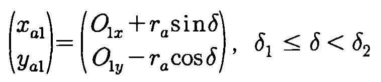
여기에서 점 O a 1(O 1 x , O 1 y )는 반지름이 γ a 인 원의 중심점 좌표이며, 점 P 1 및 P 2의 좌표를 구하면 <수학식 15>와 같다.Here, the point O a 1 ( O 1 x , O 1 y ) is the coordinate of the center point of the circle having the radius γ a , and the coordinates of the points P 1 and P 2 are obtained as shown in <Equation 15>.
![]()
![]()
한편, 전술한 도 5를 참조하면 점 P 1 및 P 2의 좌표는 하기의 <수학식 16>을 통해 구할 수 있다.Meanwhile, referring to FIG. 5 described above, the coordinates of the points P 1 and P 2 may be obtained through Equation 16 below.
![]()
![]()
상기 <수학식 15>와 <수학식 16>에서 점 P 1 및 P 2의 x, y좌표값은 동치이므로 하기의 <수학식 17> 및 <수학식 18>과 같은 관계식을 얻을 수 있다.In the above <Equation 15> and <Equation 16>, since the x and y coordinate values of the points P 1 and P 2 are the same, a relational expression such as the following <Equation 17> and <Equation 18> can be obtained.


상기 도 5에서와 같이 원의 접선에서의 성질에 따라 점 P 1에서의 C a 1 곡선의 접선은 반지름의 선분과 수직으로 만나므로 δ 1은 <수학식 19>와 같이 표현된다.As shown in FIG. 5, since the tangent of the C a 1 curve at the point P 1 is perpendicular to the radial line segment, δ 1 is expressed by Equation 19 according to the properties of the tangent of the circle.
![]()
![]()
여기에서 β 1은 상기의 <수학식 12> 및 <수학식 13>에서 하기의 <수학식 20>과 같이 구할 수 있다. Β 1 can be obtained from

또한 β 1, β 2 및 β 3사이에서는 <수학식 21>과 같은 관계가 성립한다.In addition, between β 1, β 2 and β 3 is established a relationship such as the <Equation 21>.

여기에서 β 3은 하기의 <수학식 30>과 같이 표현된다. Β 3 is represented by the following <Equation 30>.
(3) C e 곡선(3) C e curve
전술한 도 6에서 C e 곡선위의 점을 (x e , y e )라 하면 다음과 같은 <수학식 22>가 성립한다.In the aforementioned FIG. 6, when the point on the C e curve is ( x e , y e ), the following <Equation 22> is established.

전술한 도 6에서와 같이 구름원이 이동할 때 에피 사이클로이드 곡선의 기초원 반경과 구름원 이동각 사이에는 <수학식 23>과 같은 관계가 성립한다.As shown in FIG. 6, when the cloud circle moves, a relationship as shown in Equation 23 is established between the base circle radius of the epicycloid curve and the cloud circle moving angle.
![]()
![]()
상기의 <수학식 21>을 참조하여 <수학식 23>을 정리하면 하기의 <수학식 24>와 같다.Referring to <Equation 21>, <Equation 23> is summarized as in <Equation 24> below.

또한 점 P 2 부근의 C e 곡선에서 구름원의 이동각 및 회전각 사이에 <수학식 25>와 같은 관계식이 성립한다.In addition, in the C e curve near the point P 2 , a relational expression such as <Equation 25> is established between the moving angle and the rotation angle of the rolling circle.
![]()
![]()
상기의 <수학식 25>에 <수학식 24>를 대입하여 정리하면 다음과 같은 <수학식 26>을 얻을 수 있다.By substituting <Equation 24> into the above <Equation 25>, the following <Equation 26> can be obtained.

한편, ΔO 1 P 2 O e 에서 제2 코사인 법칙을 적용하면 다음과 같은 <수학식 27>을 얻을 수 있다.On the other hand, when applying a second cosine law in Δ O 1 P 2 O e can be obtained the following <Equation 27>.
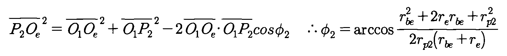
또한 C e 곡선의 구름원과 기초원 반경 사이에서는 <수학식 28>과 같은 관계식이 성립한다.In addition, a relational expression such as < Equation 28 > holds between the rolling circle and the base circle radius of the C e curve.
![]()
![]()
마찬가지로 ΔO e O 1 P 2에서 제2 코사인 법칙을 적용하면 다음과 같은 <수학식 29>를 얻을 수 있다.Similarly, by applying the second cosine law in Δ O e O 1 P 2 , the following <Equation 29> can be obtained.

이때 cos(π-θ e )=-cosθ e 이므로 상기의 <수학식 19> 및 <수학식 20>을 연립하면 β 3를 <수학식 30)과 같이 구할 수 있다.At this time, since cos (π- θ e ) =-cos θ e , the equations (19) and (20) above can be combined to obtain β 3 as shown in <Equation 30).

따라서, C e 곡선의 구성방정식은 <수학식 31>과 같이 표현된다.Therefore, the structural equation of the C e curve is expressed as in <Equation 31>.

(4) C a 2 곡선(4) C a 2 curve
도 7에서 도시한 바와 같이, C a 2 곡선위의 점을 (x a 2, y a 2)라 하면 다음과 같은 <수학식 32>가 성립한다.As shown in FIG. 7, when the point on the C a 2 curve is ( x a 2 , y a 2 ), the following <Equation 32> is established.

여기에서 (O 2 x , O 2 y )는 반지름이 γ i 인 원 C 2의 중심점 좌표이며, 점 P 3 및 P 4의 좌표를 구하면 <수학식 33>과 같다.Here, ( O 2 x , O 2 y ) is the coordinate of the center point of the circle C 2 whose radius is γ i , and the coordinates of the points P 3 and P 4 are obtained as shown in Equation 33.
![]()
![]()
한편, 상기 도 6을 참조하면, 점 P 3 및 P 4의 좌표는 하기의 <수학식 34>와 같이 구할 수 있다.Meanwhile, referring to FIG. 6, the coordinates of the points P 3 and P 4 can be obtained as shown in Equation 34 below.

상기의 <수학식 33>과 <수학식 34>에서 점 P 3 및 P 4의 x, y좌표값은 동치이므로 하기의 <수학식 35>, <수학식 36>, <수학식 37>과 같은 관계식을 각각 얻을 수 있다.In the above <Equation 33> and <Equation 34>, the x and y coordinate values of the points P 3 and P 4 are the same, so that the following <Equation 35>, <Equation 36>, and <Equation 37> We can get each relation.


또한, 전술한 도 3에서와 같이 원 C 1과 C 2의 중심점은 점 O 1를 지나고 기울기가 반 피치 각도인 직선에 의해 대칭이므로 중심점 O a 2(O 2 x , O 2 y )은 하기의 <수학식 38>과 같이 표현되며, 여기에서 O 1 x , O 1 y 의 값은 전술한 <수학식 17>과 같다.In addition, as shown in FIG. 3, the center points of circles C 1 and C 2 are symmetrical by a straight line passing through the point O 1 and having a half pitch angle, and thus the center point O a 2 ( O 2 x , O 2 y ) is It is represented by <Equation 38>, and the values of O 1 x and O 1 y are the same as in <Equation 17>.

(5) C h 2 곡선(5) C h 2 curve
전술한 도 8에서 C h 2 곡선위의 점을 (x h 2, y h 2)라 하면 다음과 같은 <수학식 39>가 성립한다.Referring to FIG. 8, the point on the C h 2 curve is ( x h 2 , y h 2 ), and the following Equation 39 is established.

전술한 도 3에서와 같이, 구름원이 이동할 때 하이포 사이클로이드 곡선의 기초원 반경과 구름원 이동각과의 관계는 하기의 <수학식 40>과 같다.As shown in FIG. 3, when the rolling circle moves, the relationship between the base circle radius of the hypocycloid curve and the rolling circle moving angle is expressed by Equation 40 below.

상기의 <수학식 40>을 이용하여 <수학식 39>를 정리하면 하기의 <수학식 41>과 같다.Using <Equation 40>, <Equation 39> is summarized as in <

다음으로, 본 발명에 따른 변수 설정 및 경계 조건식을 유도하는 방법을 구체적으로 설명한다.Next, a method of deriving the variable setting and the boundary condition equation according to the present invention will be described in detail.
먼저, 입력받게 되는 Z 1, e, ![]()
![]()
(1) 제1 경계 조건식(1) First boundary condition equation
점 P 1에서 C h 1 곡선곡선의 접선 기울기는 C a 1 곡선의 접선 기울기와 같으므로 <수학식 42>와 같은 관계식이 성립한다.Since the tangent slope of the C h 1 curve at the point P 1 is the same as the tangent slope of the C a 1 curve, the relation shown in Equation 42 is established.

또한 점 P 1에서 C h 1 곡선의 x좌표값은 하기의 <수학식 43>과 같으며, 같으며 y좌표값에 대한 수학식은 이와 동치이다.In addition, the x coordinate value of the C h 1 curve at the point P 1 is equal to the following Equation 43, and the equation for the y coordinate value is the same.

상기의 <수학식 42> 및 <수학식 43>을 연립하여 정리하면 다음과 같은 <수학식 44>를 얻을 수 있다.If the above <Equation 42> and <Equation 43> are combined and arranged, the following <Equation 44> can be obtained.

(2) 제2 경계 조건식(2) second boundary condition equation
점 P 2에서 C e 곡선의 접선 기울기는 C a 1 곡선의 접선 기울기와 같으므로 하기의 <수학식 45>와 같은 관계식이 성립한다.Since the tangential slope of the C e curve at the point P 2 is the same as the tangential slope of the C a 1 curve, the following relational expression is established.

점 P 2에서 C e 곡선의 x좌표값은 하기의 <수학식 46>과 같으며, y좌표값에 대한 수학식은 이와 동치이다.The x coordinate value of the C e curve at point P 2 is equal to <

상기의 <수학식 45> 및 <수학식 46>을 연립하여 정리하면 다음과 같은 <수학식 47>을 얻을 수 있다.If the above <Equation 45> and <

(3) 제3 경계 조건식(3) Third boundary condition equation
전술한 <수학식 17>과 <수학식 18>에서 점 P 1 및 P 2의 x좌표값은 하기의 <수학식 48>과 같다.In the above-described <Equation 17> and <Equation 18>, the x coordinate values of the points P 1 and P 2 are the same as the following <Equation 48>.
![]()
![]()
상기의 <수학식 48>을 연립하여 정리하면 다음과 같은 <수학식 49>를 얻을 수 있다.If the above <Equation 48> is combined and arranged, the following <Equation 49> can be obtained.
![]()
![]()
(4) 제4 경계 조건식(4) Fourth boundary condition equation
전술한 <수학식 35>와 <수학식 36>에서 점 P 1 및 P 2의 x좌표값은 하기의 <수학식 50>과 같다.In the above-described <Equation 35> and <Equation 36>, the x coordinate values of the points P 1 and P 2 are the same as the following <Equation 50>.

상기의 <수학식 50>을 연립하여 정리하면 다음과 같은 <수학식 51>을 얻을 수 있다.If the above <Equation 50> is combined and rearranged, the following <Equation 51> can be obtained.

(5) 제5 경계 조건식(5) Fifth boundary condition equation
전술한 도 5에서 ![]()
![]()

다음으로, 본 발명에 따른 변수에 대한 범위를 설정하는 방법에 대해서 상세하게 설명한다.Next, a method for setting a range for a variable according to the present invention will be described in detail.
먼저, 전술한 도 3에서 보는 바와 같이 γ p 1<γ bh <γ be <γ p 2의 관계가 성립하며, 이는 다음의 경우로 나누어 생각해 볼 수 있다.First, as shown in FIG. 3 described above, a relationship of γ p 1 < γ bh < γ be < γ p 2 is established, which can be considered by dividing into the following cases.
![]()
![]()
![]()
![]()
![]()
![]()
그리고, 나머지 γ p 1<γ p 2 및 γ bh <γ be 는 원호(Arc) 곡선이 삽입된다면 저절로 성립된다. 또한, C h 1 곡선 위에 점 P 1가 존재하고, C e 곡선 위에 점 P 2가 존재한다면 하기의 <수학식 56>과 같은 관계식이 성립한다.And, the remaining γ p 1 < γ p 2 and γ bh < γ be are established by themselves if an arc curve is inserted. Further, the curve point C h 1 P 1 is present and, as a C e to, if point P 2 is on the curve <Equation 56> relational expression above is satisfied.
![]()
![]()
추가로 모든 arccos(k) 형태의 값에서 |k|<1이 만족되어야 한다.In addition, for all arccos ( k ) values, | k | <1 must be satisfied.
다음으로, 본 발명에서는 Visual Basic, Auto LISP 및 Auto CAD를 이용하여 내부로터를 설계하였다.Next, in the present invention, the internal rotor was designed using Visual Basic, Auto LISP, and Auto CAD.
즉, 입력받은 Z 1, e, ![]()
![]()

이에 도 9와 같이 내부로터를 생성하였다. 이 때 Z 1 =9, e=1.35, ![]()
![]()
![]()
![]()
한편, 본 발명에서는 위와 같이 내부로터의 기하학적 분석을 통해서 얻어진 데이터를 이용하여 외부로터를 창출하는 방법을 도 10 내지 도 12를 참조하여 구체적으로 설명하면 다음과 같다.Meanwhile, in the present invention, a method of creating an external rotor using data obtained through geometrical analysis of the internal rotor as described above will be described in detail with reference to FIGS. 10 to 12.
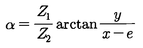
먼저, 로터 회전시뮬레이션은 내부로터를 외부로터 중심점 O 2(0, 0)을 중심으로하여 CCW 방향으로 각도 α만큼 공전시키고 공전된 내부로터의 중심점을 중심으로 내부로터를 다시 CW 방향으로 ![]()
![]()
즉, 도 10의 회전 시뮬레이션 분석 결과, 내부로터와 같이 공전하는 기준축(x축)이 회전 후의 내부로터와 교점을 생성하며, 그 교점에서 축방향으로 t p 만큼 떨어진 점이 외부로터를 구성함을 알 수 있다. 이를 수학식으로 표현하면 <수학식 58>과 같다. 여기에서 외부로터를 구성하는 점의 좌표를 (X, Y), 내부로터를 구성하는 점의 좌표를 (x, y)라 한다.That is, as a result of the rotation simulation analysis of FIG. 10, the reference axis (x-axis) revolving like the inner rotor generates an intersection with the inner rotor after rotation, and a point away from the intersection by t p in the axial direction constitutes the outer rotor. Able to know. This may be expressed as Equation 58. Here, the coordinates of the points constituting the external rotor ( X , Y ) and the coordinates of the points constituting the internal rotor are ( x , y ).

공전하는 기준축과의 교점이 외부로터를 구성하므로 하기의 <수학식 58>과 같은 관계식이 성립한다.Since the intersection with the revolving reference axis constitutes the external rotor, the following relational expression is established.
![]()
![]()
상기의 <수학식 58> 및 <수학식 59>를 연립하여 풀면 다음과 같은 <수학식 60>을 얻을 수 있다.When the above formulas (58) and (59) are combined and solved, the following formula (60) can be obtained.
위와 같이 내부로터의 구성방정식을 바탕으로 내부로터를 생성하고, 상기의 <수학식 58>과 <수학식 60>을 이용하여 외부로터를 창출한 결과 도 11에서와 같이 일정구간 간섭이 발생하였다.As described above, the internal rotor was generated based on the configuration equation of the internal rotor, and the external rotor was created using Equation 58 and Equation 60, as shown in FIG.
로터 회전시뮬레이션 수행결과, 도 11의 상부도면과 같이 내부로터의 하이포 사이클로이드 곡선 및 원호 곡선부분에서는 전체간섭이 발생하였고, 에피 사이클로이드 곡선부분에서는 부분간섭이 발생하였다. 또한 도 11의 하부도면과 같이 내외부로터를 각각의 중점을 중심으로 반 피치각도만큼 CCW으로 회전한 뒤, 도 3의 점 P 1을 x축에 대칭시킨 내부로터 상의 점이 변환된 외부로터 상의 점(P 1')에서 최대 간섭량이 발생하였다. 이에 수정폭 계수를 n, 수정범위 계수를 k로 정의한 후, 점 P 1'와 가장 가까운 점간거리를 갖는 내부로터위의 점 사이의 거리를 도 14에서의 팁 간극(t p : tip clearance)으로 설정하였다.As a result of the rotor rotation simulation, overall interference occurred in the hypocycloid curve and the arc curve portion of the inner rotor, and partial interference occurred in the epicycloid curve portion, as shown in the top view of FIG. In addition, as shown in the bottom view of FIG. 11, the inner and outer rotors are rotated by CCW by a half pitch angle around each midpoint, and then the points on the inner rotors in which the points P 1 of FIG. 3 are symmetrical to the x-axis are converted ( The maximum amount of interference occurred at P 1 ′). Therefore, after defining the correction width coefficient n and the correction range coefficient k , the distance between the point P 1 ′ and the point on the inner rotor having the closest point distance is defined as the tip clearance in Fig. 14 ( t p : tip clearance). Set.
또한 내부로터의 하이포 사이클로이드 및 원호 곡선 부분에서는 전체간섭이 발생하였으므로 수정폭 계수 n을 적용하고, 에피 사이클로이드 곡선 부분에서는 부분간섭이 발생하였으므로 수정범위 계수 k가 적용된 범위까지는 수정폭 계수 n을 적용, 그 이후 범위각부터 외부로터의 반 피치각도까지는 가변등차간격을 갖는 수정폭 계수를 적용하였다.Also, since the total interference occurred in the hypocycloid and arc curve parts of the inner rotor, the correction width coefficient n was applied, and the partial width interference occurred in the epicycloid curve portion, so the correction width coefficient n was applied to the range where the correction range coefficient k was applied. After that, a modified width coefficient with variable differential intervals was applied from the range angle to the half pitch angle of the external rotor.
이때, 내부로터의 에피 사이클로이드 곡선 위의 점들이 변환된 점들로써 구성된 외부로터 곡선은 내외부로터 사이의 원활한 슬라이딩을 위해 점 O 1(0,0)을 기준으로 바깥쪽으로 볼록한 함수의 형상이어야한다. 전 구간에서 볼록한 함수 중에서 대표적인 2차 다항식은 2차항 계수 즉, 2계미분값의 부호가 양수이면 아래로 볼록한 특성을 갖는다.At this time, the outer rotor curve composed of the points transformed on the epicycloid curve of the inner rotor should have the shape of a convex function outwardly based on the point O 1 (0,0) for smooth sliding between the inner and outer rotors. Representative quadratic polynomials among the convex functions in the entire interval have convex characteristics when the quadratic coefficient, that is, the sign of the second derivative is positive.
이와 같은 특성을 이용하기 위해 상기 외부로터 곡선 위에서 연속한 4개의 점을 추출하여 수정폭 계수 n 및 가변등차간격을 갖는 수정폭 계수를 적용하였다. 이는 볼록함수일 경우, 4개의 점 각각을 연결한 세 개의 선분의 기울기(1계미분)가 증가(2계미분) 또는 기울기가 음수일 경우 양의 x축으로부터의 기울기 각도가 증가함을 이용한 것이다. 이에 <수학식 58> 및 <수학식 60>을 이용한 외부로터 반 피치 각도 구간까지의 각 구간별 외부로터 구성방정식은 다음과 같은 <수학식 61> 내지 <수학식 65>으로 유도된다.In order to use this characteristic, four continuous points on the outer rotor curve were extracted, and a correction width coefficient having a fixed width coefficient n and a variable differential interval was applied. In the case of the convex function, the slope (first derivative) of three lines connecting each of the four points is increased (second derivative) or the slope angle from the positive x-axis increases when the slope is negative. Accordingly, the external rotor configuration equation for each section up to the external rotor half pitch angle section using Equations 58 and 60 is derived from Equations 61 to 65 as follows.


상기한 바와 같이, 내부로터의 반 피치 구간에 해당하는 점까지 외부로터로 변환한 뒤 외부로터의 반 피치 지점에서 대칭시켜 한 피치 구간의 외부로터를 구성한 후 외부로터의 잇수만큼 배열하여 외부로터를 도 12와 같이 생성하였다. 이때, 외부로터 이끝폭 w o 는 도 3의 점 P 1이 변환된, <수학식 62>에서 δ=δ 1일 때의 Y a 1값의 2배와 같다.As described above, convert the outer rotor to the point corresponding to the half pitch section of the inner rotor and symmetrically at the half pitch point of the outer rotor to form the outer rotor of one pitch section, and then arrange the outer rotor by the number of teeth of the outer rotor. It produced as shown in FIG. At this time, the outer rotor tip width w o is equal to twice the value of Y a 1 when δ = δ 1 in Equation 62 where the point P 1 of FIG. 3 is converted.
위에서 본 바와 같이, 본 발명에서는 내부로터에서 외부로터의 궤적을 창출하여 지로터 오일펌프의 로터를 설계하는 시스템을, 바람직하게는 하이포 사이클로이드 곡선과 에피 사이클로이드 사이에 원호 곡선을 삽입한 방식의 내부로터를 먼저 구성하고 이로부터 외부로터를 창출하여 지로터 오일펌프의 로터를 설계할 수 있는 시스템을 구체적으로 설명하였다.As seen from above, in the present invention, a system for designing a rotor of a rotor rotor oil pump by creating a trajectory of an outer rotor in the inner rotor, preferably an inner rotor in which an arc curve is inserted between a hypocycloid curve and an epicycloid. First, we explained the system that can design the rotor of the GROTOR oil pump by constructing the external rotor and creating an external rotor from it.
하기에는 이를 바탕으로 하여 내외부로터의 성능인자를 계산하는 방법을 상세하게 설명하고자 하며. 구체적으로는 '(1)유량 및 유량맥동 계산' 및 '(2)한계조건을 고려한 지로터 펌프 설계'를 나누어 설명할 것이다.In the following, it will be described in detail how to calculate the performance factors of the internal and external rotor based on this. Specifically, the description will be divided into (1) flow rate and flow rate pulsation calculation and (2) Gerotor pump design considering the limit conditions.
(1) 유량 및 유량맥동 계산(1) Flow rate and flow pulsation calculation
순간유량(Q㎣/rad)이란 내부로터 및 외부로터가 회전하면서 내외부로터 간 챔버의 면적이 줄어드는 것에서의 회전각도 대비 면적변화량을 뜻하며, 그 단위로는 (cc/rev) 또는 r줄어조건이 주어질 경우 (㎤/sec) 등으로 표현 가능하다. 이때 로터의 두께는 7.2로 설정하였다.The instantaneous flow rate ( Q ㎣ / rad ) means the change in area compared to the rotation angle in which the area of the chamber between the inner and outer rotor decreases as the inner and outer rotors rotate, and the unit ( cc / rev ) or r decreases. (Cm 3 / sec) or the like. At this time, the thickness of the rotor was set to 7.2.
도 13-1에서 보는 바와 같이, 도 12의 내외부로터가 각각의 중심점을 중심으로 반 피치각도만큼 CCW방향으로 회전한 후 내외부로터 사이에서 발생하는 챔버 중 CCW방향으로 회전함에 따라 그 면적이 줄어드는 챔버를 음영으로 표시하였다. 이때, 챔버의 경계영역은 일정구간 내에서 가장 가까운 점간거리를 갖는 내외부로터 위의 점을 연결한 후 그 사이를 연결하는 내외부로터 형상으로 지정하였다.As shown in FIG. 13-1, the chamber of which the area decreases as the inner and outer rotors of FIG. 12 rotate in the CCW direction by a half pitch angle around each center point and then rotate in the CCW direction among the chambers generated between the inner and outer rotors. Are shaded. At this time, the boundary region of the chamber was designated as an inner and outer rotor shape connecting the points on the inner and outer rotors having the closest point distance in a predetermined section and then connecting them.
외부로터가 O 2(0,0)을 중심으로 Δα만큼 CCW방향으로 회전할 때 내부로터는 O 1(e,0)을 중심으로 (Z 2/Z 1)Δα만큼 같은 방향으로 회전하며, 이에 따라 도 13-2에서와 같이 음영으로 표시된 챔버의 면적이 감소한다. 따라서 도 13-1의 형상에서 외부로터가 반 피치 각도만큼 회전하면 도 13-3의 챔버 형상으로 변화하며 이에 Δα만큼 외부로터가 회전함에 따라 음영으로 표시된 챔버의 면적이 S k 에서 S k +1로 변화했다면, 순간유량은 하기의 <수학식 66>에 의해 계산된다.When the outer rotor rotates in the CCW direction by Δ α around O 2 (0,0), the inner rotor rotates in the same direction by ( Z 2 / Z 1 ) Δ α around O 1 ( e , 0). Accordingly, the area of the chamber shaded as shown in FIG. 13-2 is reduced. Therefore, even in the shape of the outer rotor 13-1 is changed to the shape of the chamber 13-3 also rotates by half a pitch angle, and this Δ α S k + S k in the area of the chamber as the outer rotor rotates as indicated by the shaded If it is changed to 1 , the instantaneous flow rate is calculated by the following formula (66).

또한 평균유량 q av는 외부로터 반 피치 구간에서 순간유량의 평균값으로 구할 수 있으며 그 관계식은 하기의 <수학식 67>과 같다.In addition, the average flow rate q av can be obtained as the average value of the instantaneous flow rate in the outer rotor half pitch section, and the relationship thereof is expressed by Equation 67 below.

도 13의 외부로터 반 피치 구간내의 순간유량값 중에서 최대값을 q max, 최소값을 q min이라고 하면, 유량맥동값 I(%)는 하기의 <수학식 68>에 의해 계산된다.Among the instantaneous flow rate values in the outer rotor half pitch section of FIG. 13, if the maximum value is q max and the minimum value is q min , the flow rate pulsation value I (%) is calculated by the following equation (68).
![]()
![]()
도 13-3의 로터 형상에서 내외부로터 회전이 계속 진행되면 도 13-1의 형상으로 변화하며, 이는 13-1 내지 도 13-3 구간에서 음영으로 표시된 챔버의 면적이 역으로 변화하므로 외부로터 회전각의 변화에 따른 순간유량 변화양상은 도 13-1일 때를 기준으로 좌우대칭을 이룬다. 이를 바탕으로 외부로터 회전각에 대한 유량의 변화양상을 도식화한 결과는 도 15와 같다. 여기에서 순간유량이 임의의 폭을 기준으로 진동하므로 <수학식 66>에서의 Sk 를 3차 다항식으로 회귀분석한 결과 결정계수값은 1을 가지며, 회귀분석된 챔버 면적을 이용하여 유량의 변화양상을 도식화하였으며 동시에 내외부로터의 편심량, ![]()
![]()
(2) 한계조건을 고려한 지로터 펌프 설계(2) Gerotor pump design considering limit conditions
제작상의 한계조건 때문에 내외부로터의 이끝 폭(wi /wo )이 2mm보다 작게되지 않아야 함을 명시하고 있다. 도 14를 참조하여, Z 1 =9, DBP=0.005, ρ 2max =12, w=7.2, tp =0.025이고 e가 1.32일 때, ![]()
![]()
하기의 표 1에서는 상기 경우의 출력값들을 보여주고 있다.Table 1 below shows the output values in this case.

상기 표 1에서 e를 고정하고 ![]()
![]()
![]()
![]()
![]()
![]()
이러한 경향을 토대로 편심량을 1.26에서 1.41까지 0.01 단위로 변화시키며 0.1˚단위에서의 한계 ![]()
![]()

표 2에서 편심량이 증가할수록 평균유량 및 유량맥동값이 증가하여 유량 특성은 좋아지나 유량맥동은 나빠짐을 알 수 있다. 표 3은 상기 표 2에서 제시하고 있는 로터 중 편심량이 1.26, 1.29, 1.32, 1.35, 1.38, 1.41일 때의 6개에 대한 형상을 나타내고 있다.In Table 2, as the eccentricity increases, the average flow rate and flow rate pulsation value increase, so that the flow rate characteristics are improved, but the flow rate pulsation is worsened. Table 3 shows the shapes of six of the rotors shown in Table 2 when the eccentricity is 1.26, 1.29, 1.32, 1.35, 1.38, and 1.41.

Claims (4)
하이포 사이클로이드 곡선과 에피 사이클로이드 곡선의 사이에 원호 곡선을 삽입하여 내부로터를 구성하는 과정과,
상기 내부로터에서 외부로터의 궤적을 창출하는 과정으로 이루어짐을 특징으로 하는 다양한 치형곡선을 이용한 지로터 오일펌프의 로터 설계 방법.In the method of designing the rotor of the Gerotor oil pump using various tooth curves,
Inserting an arc curve between the hypocycloid curve and the epi cycloid curve to construct the inner rotor,
Rotor design method of a rotor rotor oil pump using a variety of teeth curve characterized in that the process of creating a trajectory of the outer rotor in the inner rotor.
편심량이 e인 지로터의 내부로터 중심점 O 1 =(e, 0)을 기준으로 한 피치각도의 β 1 및 β 5만큼 하이포 사이클로이드 곡선으로, β 2 및 β 4만큼 원호 곡선으로, β 3만큼 에피 사이클로이드 곡선으로 조합된 내부로터의 구성방정식을 유도하는 과정으로 이루어짐을 특징으로 하는 다양한 치형곡선을 이용한 지로터 오일펌프의 로터 설계 방법.The method of claim 1,
The eccentricity of e is not the inner rotor center O 1 = the pitch angle based on the (e, 0) β 1 and β 5 as hypo-cycloid curve of the rotor, the β 2 and β 4 as the arcuate curve, β 3 by epi Rotor design method of the rotor rotor pump using a variety of tooth curves characterized in that the process consisting of inducing the configuration equation of the internal rotor combined by the cycloid curve.
상기 원호 곡선의 곡률반경은 γa , 하이포 사이클로이드 곡선 및 에피 사이클로이드 곡선의 구름원 반경을 각각 γh , γe 이라고 하고, 내부로터 중심점 O 1(e,0)을 중심으로 하이포 사이클로이드 곡선과 원호 곡선의 연결점을 지나는 원의 반경을 γp 1, 원호 곡선과 에피 사이클로이드 곡선의 연결점을 지나는 원의 반경을 γp 2라고 한다. 또한 x축으로부터 첫 번째 하이포 사이클로이드 곡선을 Ch 1, 두 번째 원호 곡선을 Ca 1, 세 번째 에피 사이클로이드 곡선을 Ce , 네 번째 원호 곡선을 Ca 2, 마지막 하이포 사이클로이드 곡선을 Ch 2라 할 때;
상기 하이포 사이클로이드 곡선(Ch 1)은 하기 <수학식 7> 내지 <수학식 13>에 의해 결정되며,
상기 원호 곡선(Ca 1)은 하기 <수학식 14> 내지 <수학식 21>에 의해 결정되며,
상기 에피 사이클로이드 곡선(Ce )은 하기 <수학식 22> 내지 <수학식 31>에 의해 결정되며,
상기 원호 곡선(Ca 2)은 하기 <수학식 32> 내지 <수학식 38>에 의해 결정되며,
상기 하이포 사이클로이드 곡선(Ch 2)은 <수학식 39> 내지 <수학식 41>에 의해 결정됨을 특징으로 하는 다양한 치형곡선을 이용한 지로터 오일펌프의 로터 설계 방법.
[수학식 7]
[수학식 8]
[수학식 9]

[수학식 10]
[수학식 11]

[수학식 12]

[수학식 13]

[수학식 14]
[수학식 15]
[수학식 16]
[수학식 17]

[수학식 18]

[수학식 19]
[수학식 20]

[수학식 21]
[수학식 22]

[수학식 23]
[수학식 24]
[수학식 25]
[수학식 26]
[수학식 27]

[수학식 28]
[수학식 29]

[수학식 30]

[수학식 31]

[수학식 32]
[수학식 33]
[수학식 34]

[수학식 35]
[수학식 36]

[수학식 37]

[수학식 38]

[수학식 39]

[수학식 40]
[수학식 41]

The radius of curvature of the arcuate curve is γ a, the hypo-cycloid curve and epi cycloid, and that each of γ h, γ e a generating circle radius of the curve, the inner rotor center O 1 (e, 0) centered in the hypo-cycloid curve and the circular arc curve of The radius of the circle passing through the connection point of γ p 1 is called γ p 2 , and the radius of the circle passing through the connection point of the arc and epicycloid curves is called γ p 2 . Also, from the x-axis, the first hypocycloid curve C h 1 , the second arc curve C a 1 , the third epi cycloid curve C e , the fourth arc curve C a 2 , and the last hypocycloid curve C h 2 when doing;
The hypocycloid curve C h 1 is determined by the following Equations 7 to 13,
The arc curve ( C a 1 ) is determined by the following Equations 14 to 21,
The epicycloid curve C e is determined by the following Equations 22 to 31,
The arc curve C a 2 is determined by the following Equations 32 to 38,
The hypocycloid curve ( C h 2 ) is determined by the equations (39) to (41).
&Quot; (7) "
&Quot; (8) "
[Equation 9]
[Equation 10]
[Equation 11]
[Equation 12]
[Equation 13]
[Equation 14]
[Equation 15]
[Equation 16]
[Equation 17]
Equation 18
[Equation 19]
[Equation 20]
[Equation 21]
[Equation 22]
[Equation 23]
[Equation 24]
[Equation 25]
[Equation 26]
[Equation 27]
[Equation 28]
[Equation 29]
Equation 30
Equation 31
Equation 32
[Equation 33]
[Equation 34]
[Equation 35]
[Equation 36]
[Equation 37]
[Equation 38]
[Equation 39]
[Equation 40]
[Equation 41]
상기 내부로터에 따른 외부로터는 하기 <수학식 61> 내지 <수학식 65>에 의해 결정됨을 특징으로 하는 다양한 치형곡선을 이용한 지로터 오일펌프의 로터 설계 방법.
[수학식 61]

[수학식 62]

[수학식 63]

[수학식 64]

[수학식 65]

The rotor design method of the rotor rotor pump using a variety of teeth curve, characterized in that the external rotor according to the inner rotor is determined by the following formula (Equation 61) to <Equation 65>.
Equation 61
Equation 62
Equation 63
Equation 64
[Equation 65]
Priority Applications (1)
| Application Number | Priority Date | Filing Date | Title |
|---|---|---|---|
| KR1020100033621A KR101101610B1 (en) | 2010-04-09 | 2010-04-09 | Method for designing the gerotor pump |
Applications Claiming Priority (1)
| Application Number | Priority Date | Filing Date | Title |
|---|---|---|---|
| KR1020100033621A KR101101610B1 (en) | 2010-04-09 | 2010-04-09 | Method for designing the gerotor pump |
Publications (2)
| Publication Number | Publication Date |
|---|---|
| KR20110113541A KR20110113541A (en) | 2011-10-17 |
| KR101101610B1 true KR101101610B1 (en) | 2012-01-02 |
Family
ID=45028877
Family Applications (1)
| Application Number | Title | Priority Date | Filing Date |
|---|---|---|---|
| KR1020100033621A KR101101610B1 (en) | 2010-04-09 | 2010-04-09 | Method for designing the gerotor pump |
Country Status (1)
| Country | Link |
|---|---|
| KR (1) | KR101101610B1 (en) |
Cited By (1)
| Publication number | Priority date | Publication date | Assignee | Title |
|---|---|---|---|---|
| KR20180089593A (en) | 2017-01-31 | 2018-08-09 | 계명대학교 산학협력단 | Method of designing tooth profile of gerotor pump and gerotor pump manufactured by it |
Families Citing this family (5)
| Publication number | Priority date | Publication date | Assignee | Title |
|---|---|---|---|---|
| KR101251632B1 (en) * | 2011-12-30 | 2013-04-08 | 부산대학교 산학협력단 | Gerotor oil pump and method for designing the same |
| CN108253115B (en) * | 2017-12-11 | 2019-08-09 | 广州市昊志机电股份有限公司 | A method of the form of cycloidal gear tooth is obtained based on pinwheel tooth profiling quantity |
| CN109084006B (en) * | 2018-09-21 | 2020-09-11 | 中车戚墅堰机车车辆工艺研究所有限公司 | Trigonometric function shape modifying method for cycloid gear and cycloid pin gear speed reducer |
| KR102040416B1 (en) * | 2018-11-06 | 2019-11-04 | 군산대학교산학협력단 | Generation method of mate-rotor 1obe profile and Mate-rotor using the same method |
| KR102430059B1 (en) * | 2020-12-03 | 2022-08-10 | 근로복지공단 | Design method for cycloid gear |
Citations (1)
| Publication number | Priority date | Publication date | Assignee | Title |
|---|---|---|---|---|
| KR102319966B1 (en) * | 2019-12-31 | 2021-11-02 | 세메스 주식회사 | Chemical supplying unit, substrate treating apparatus and substrate treating method |
-
2010
- 2010-04-09 KR KR1020100033621A patent/KR101101610B1/en active IP Right Grant
Patent Citations (1)
| Publication number | Priority date | Publication date | Assignee | Title |
|---|---|---|---|---|
| KR102319966B1 (en) * | 2019-12-31 | 2021-11-02 | 세메스 주식회사 | Chemical supplying unit, substrate treating apparatus and substrate treating method |
Non-Patent Citations (1)
| Title |
|---|
| "지로터 펌프/모터의 치형설계 프로그램 개발에 관한 연구", 한국윤활학회 학술강연회 제23권, pp. 17-23, 1996.6.* |
Cited By (1)
| Publication number | Priority date | Publication date | Assignee | Title |
|---|---|---|---|---|
| KR20180089593A (en) | 2017-01-31 | 2018-08-09 | 계명대학교 산학협력단 | Method of designing tooth profile of gerotor pump and gerotor pump manufactured by it |
Also Published As
| Publication number | Publication date |
|---|---|
| KR20110113541A (en) | 2011-10-17 |
Similar Documents
| Publication | Publication Date | Title |
|---|---|---|
| KR101101610B1 (en) | Method for designing the gerotor pump | |
| KR100940980B1 (en) | Gerotor oil pump | |
| JP4243498B2 (en) | Ring gear machine clearance | |
| Panchenko et al. | The Influence of the form error after rotor manufacturing on the output characteristics of an orbital hydraulic motor | |
| CN107642592B (en) | Double helical gear with variable helix angle and non-encapsulated tooth profile for hydraulic gear device | |
| KR101948229B1 (en) | Method of designing tooth profile of gerotor pump and gerotor pump manufactured by it | |
| JP2007032836A (en) | Gear using arc tooth profile, internal gear pump, gear transmission and gear manufacturing method | |
| CN103678818A (en) | Precise modeling method for biarc correction cycloidal gear | |
| Zaytsev et al. | Profile generation method for twin screw compressor rotors based on the meshing line | |
| CN101714173B (en) | Automatic plan system for gerotor oil pump with tooth form shape | |
| Karamooz Ravari et al. | Flow irregularity and wear optimization in epitrochoidal gerotor pumps | |
| JP6211591B2 (en) | Screw expander, screw machine design method, screw machine manufacturing method, screw machine and generator | |
| KR20160144948A (en) | Gerotor Pump with double rotor assembly | |
| KR101269057B1 (en) | Gerotor Pump and Method for Designing the Same | |
| KR101251632B1 (en) | Gerotor oil pump and method for designing the same | |
| JP2008138874A (en) | Gear having arcuate tooth shape and gear transmission device using the same, and gear manufacturing method | |
| KR101606815B1 (en) | Method for Designing Outer Rotor Lobe Shape Using 2 Ellipses and Gerotor Pump Designed by the Method | |
| Kwon et al. | Rotor profile design in a hypogerotor pump | |
| KR101748310B1 (en) | Rotors design method for gerotor oil pump and gerotor oil pump manufacturing through it | |
| KR20050055652A (en) | Development of an integrated system for automated design of gerotor oil pump and thereof method | |
| Prakash et al. | Design and analysis of gerotors of main gear box lubricating oil pump | |
| Pan et al. | A numerical method for the analysis of the theoretical flow in crescent-type internal gear machines with involute teeth profile | |
| KR102475876B1 (en) | Method for Designing Lobe Shape of Gerotor Oil Pump Using Lemniscate Curve And Design System of Gerotor Oil Pump Using the Same | |
| KR101238906B1 (en) | Gerotor Pump and Method for Designing the Same | |
| Lee et al. | Optimal Design of Gerotor Profile with Lemniscate Lobe Shape for Noise Reduction |
Legal Events
| Date | Code | Title | Description |
|---|---|---|---|
| A201 | Request for examination | ||
| E902 | Notification of reason for refusal | ||
| E701 | Decision to grant or registration of patent right | ||
| GRNT | Written decision to grant | ||
| FPAY | Annual fee payment |
Payment date: 20141126 Year of fee payment: 4 |
|
| FPAY | Annual fee payment |
Payment date: 20151026 Year of fee payment: 5 |
|
| FPAY | Annual fee payment |
Payment date: 20161005 Year of fee payment: 6 |
|
| FPAY | Annual fee payment |
Payment date: 20181226 Year of fee payment: 8 |