JP4169069B2 - Compressor - Google Patents
Compressor Download PDFInfo
- Publication number
- JP4169069B2 JP4169069B2 JP2006316793A JP2006316793A JP4169069B2 JP 4169069 B2 JP4169069 B2 JP 4169069B2 JP 2006316793 A JP2006316793 A JP 2006316793A JP 2006316793 A JP2006316793 A JP 2006316793A JP 4169069 B2 JP4169069 B2 JP 4169069B2
- Authority
- JP
- Japan
- Prior art keywords
- rotor
- plane
- central axis
- groove
- screw rotor
- Prior art date
- Legal status (The legal status is an assumption and is not a legal conclusion. Google has not performed a legal analysis and makes no representation as to the accuracy of the status listed.)
- Expired - Fee Related
Links
Images


Classifications
-
- F—MECHANICAL ENGINEERING; LIGHTING; HEATING; WEAPONS; BLASTING
- F04—POSITIVE - DISPLACEMENT MACHINES FOR LIQUIDS; PUMPS FOR LIQUIDS OR ELASTIC FLUIDS
- F04C—ROTARY-PISTON, OR OSCILLATING-PISTON, POSITIVE-DISPLACEMENT MACHINES FOR LIQUIDS; ROTARY-PISTON, OR OSCILLATING-PISTON, POSITIVE-DISPLACEMENT PUMPS
- F04C18/00—Rotary-piston pumps specially adapted for elastic fluids
- F04C18/48—Rotary-piston pumps with non-parallel axes of movement of co-operating members
- F04C18/50—Rotary-piston pumps with non-parallel axes of movement of co-operating members the axes being arranged at an angle of 90 degrees
- F04C18/52—Rotary-piston pumps with non-parallel axes of movement of co-operating members the axes being arranged at an angle of 90 degrees of intermeshing engagement type, i.e. with engagement of co-operating members similar to that of toothed gearing
-
- F—MECHANICAL ENGINEERING; LIGHTING; HEATING; WEAPONS; BLASTING
- F04—POSITIVE - DISPLACEMENT MACHINES FOR LIQUIDS; PUMPS FOR LIQUIDS OR ELASTIC FLUIDS
- F04C—ROTARY-PISTON, OR OSCILLATING-PISTON, POSITIVE-DISPLACEMENT MACHINES FOR LIQUIDS; ROTARY-PISTON, OR OSCILLATING-PISTON, POSITIVE-DISPLACEMENT PUMPS
- F04C18/00—Rotary-piston pumps specially adapted for elastic fluids
- F04C18/08—Rotary-piston pumps specially adapted for elastic fluids of intermeshing-engagement type, i.e. with engagement of co-operating members similar to that of toothed gearing
- F04C18/082—Details specially related to intermeshing engagement type pumps
- F04C18/084—Toothed wheels
-
- F—MECHANICAL ENGINEERING; LIGHTING; HEATING; WEAPONS; BLASTING
- F04—POSITIVE - DISPLACEMENT MACHINES FOR LIQUIDS; PUMPS FOR LIQUIDS OR ELASTIC FLUIDS
- F04C—ROTARY-PISTON, OR OSCILLATING-PISTON, POSITIVE-DISPLACEMENT MACHINES FOR LIQUIDS; ROTARY-PISTON, OR OSCILLATING-PISTON, POSITIVE-DISPLACEMENT PUMPS
- F04C18/00—Rotary-piston pumps specially adapted for elastic fluids
- F04C18/48—Rotary-piston pumps with non-parallel axes of movement of co-operating members
- F04C18/54—Rotary-piston pumps with non-parallel axes of movement of co-operating members the axes being arranged otherwise than at an angle of 90 degrees
- F04C18/56—Rotary-piston pumps with non-parallel axes of movement of co-operating members the axes being arranged otherwise than at an angle of 90 degrees of intermeshing engagement type, i.e. with engagement of co-operating members similar to that of toothed gearing
Description
この発明は、例えば空気調和機や冷蔵庫等に用いられる圧縮機に関する。 The present invention relates to a compressor used in, for example, an air conditioner or a refrigerator.
従来、圧縮機としては、中心軸まわりに回転すると共に外周面に中心軸まわりに螺旋状に延びる少なくとも1つの溝部を有する円筒状のスクリューロータと、中心軸まわりに回転すると共に外周に周方向に配列される複数の歯部を有するゲートロータとを有し、上記スクリューロータの溝部と上記ゲートロータの歯部とが噛み合って圧縮室を形成するものがある(特開平2−5778号公報:特許文献1参照)。 Conventionally, as a compressor, a cylindrical screw rotor that rotates around a central axis and that has at least one groove extending spirally around the central axis on an outer peripheral surface, and rotates around the central axis and circumferentially around the outer periphery. There is a gate rotor having a plurality of tooth portions arranged, and a groove portion of the screw rotor and a tooth portion of the gate rotor mesh with each other to form a compression chamber (JP-A-2-5778). Reference 1).
つまり、この圧縮機は、いわゆる、CP型のシングルスクリュー圧縮機である。「CP型」とは、上記スクリューロータがシリンダ状に形成され、かつ、上記ゲートロータがプレート状に形成されていることをいう。 That is, this compressor is a so-called CP type single screw compressor. “CP type” means that the screw rotor is formed in a cylinder shape, and the gate rotor is formed in a plate shape.
そして、上記ゲートロータ中心軸は、上記スクリューロータ中心軸に直交する平面に対して、平行である。つまり、上記ゲートロータの歯部は、上記スクリューロータ中心軸に沿って、上記スクリューロータの溝部に噛み合っている。 The gate rotor central axis is parallel to a plane perpendicular to the screw rotor central axis. That is, the tooth portion of the gate rotor meshes with the groove portion of the screw rotor along the screw rotor central axis.
上記ゲートロータ歯部側面には、上記スクリューロータと上記ゲートロータとの干渉を防ぐために、上記ゲートロータ平面と直交し、かつ上記ゲートロータの歯中心線の回転方向を含む平面上で、上記ゲートロータ歯部側面と上記スクリューロータ溝壁面とがなす、最大角度と最小角度(以下、最大角度と最小角度がなす角を、上記ゲートロータのエッジ角といい、図13のエッジ角度δ1、δ2を参照)が与えられている。
しかしながら、上記従来の圧縮機では、上記ゲートロータ中心軸は、上記スクリューロータ中心軸に直交する平面に対して、平行であるので、上記ゲートロータ平面と直交し、かつ上記ゲートロータの歯中心線の回転方向を含む平面上で、上記ゲートロータ歯部側面に対する上記スクリューロータ溝側面とのなす角度は、最大値と最小値との差が大きくなる。 However, in the conventional compressor, the central axis of the gate rotor is parallel to a plane orthogonal to the central axis of the screw rotor, and thus is orthogonal to the plane of the gate rotor and the tooth center line of the gate rotor. The difference between the maximum value and the minimum value of the angle between the side surface of the gate rotor and the side surface of the screw rotor groove on the plane including the rotational direction of the gate rotor becomes large.
このため、上記スクリューロータの溝部の側面と噛み合う上記ゲートロータのシール部分のエッジ角度が鋭くなって、上記スクリューロータの溝部と上記ゲートロータの歯部との噛み合い部に存在するブローホール(漏れ隙間)が大きくなって、圧縮効率が低減していた。 For this reason, the edge angle of the seal portion of the gate rotor that meshes with the side surface of the groove portion of the screw rotor becomes sharp, and the blow hole (leakage gap) that exists in the mesh portion of the groove portion of the screw rotor and the tooth portion of the gate rotor ) Increased, and the compression efficiency was reduced.
そこで、この発明の課題は、ブローホールを小さくして圧縮効率を向上する圧縮機を提供することにある。 Therefore, an object of the present invention is to provide a compressor that improves the compression efficiency by reducing the blowhole.
上記課題を解決するため、この発明の圧縮機は、
中心軸まわりに回転すると共に外周面に中心軸まわりに螺旋状に延びる少なくとも1つの溝部を有する円筒状のスクリューロータと、中心軸まわりに回転すると共に外周に周方向に配列される複数の歯部を有するゲートロータとを有し、上記スクリューロータの溝部と上記ゲートロータの歯部とが噛み合って圧縮室を形成する圧縮機において、
上記スクリューロータ中心軸を含む第1の平面と、上記スクリューロータ中心軸に直交すると共に上記スクリューロータの溝部に交差する第2の平面と、上記第1の平面および上記第2の平面に直交すると共に上記スクリューロータの溝部から離隔する第3の平面とに関して、
上記ゲートロータ中心軸は、上記第1の平面、上記第2の平面および上記第3の平面の交点を通ると共に、上記第3の平面に直交する方向からみて、上記第2の平面に対して、上記スクリューロータの溝部と同じ側に傾いており、
上記スクリューロータの溝部の数量が3個であり、上記ゲートロータの歯部の数量が12個であって、
上記第3の平面に直交する方向からみて、上記ゲートロータ中心軸は、上記第2の平面に対して、略7°で傾いており、
上記ゲートロータの歯部における上記スクリューロータの溝部に接触するシール部は、曲面状に形成されていることを特徴としている。
また、この発明の圧縮機は、
中心軸まわりに回転すると共に外周面に中心軸まわりに螺旋状に延びる少なくとも1つの溝部を有する円筒状のスクリューロータと、中心軸まわりに回転すると共に外周に周方向に配列される複数の歯部を有するゲートロータとを有し、上記スクリューロータの溝部と上記ゲートロータの歯部とが噛み合って圧縮室を形成する圧縮機において、
上記スクリューロータ中心軸を含む第1の平面と、上記スクリューロータ中心軸に直交すると共に上記スクリューロータの溝部に交差する第2の平面と、上記第1の平面および上記第2の平面に直交すると共に上記スクリューロータの溝部から離隔する第3の平面とに関して、
上記ゲートロータ中心軸は、上記第1の平面、上記第2の平面および上記第3の平面の交点を通ると共に、上記第3の平面に直交する方向からみて、上記第2の平面に対して、上記スクリューロータの溝部と同じ側に傾いており、
上記スクリューロータの溝部の数量が6個であり、上記ゲートロータの歯部の数量が12個であって、
上記第3の平面に直交する方向からみて、上記ゲートロータ中心軸は、上記第2の平面に対して、略16°で傾いており、
上記ゲートロータの歯部における上記スクリューロータの溝部に接触するシール部は、曲面状に形成されていることを特徴としている。 In order to solve the above problems, the compressor of the present invention is:
A cylindrical screw rotor that rotates around the central axis and has at least one groove extending spirally around the central axis on the outer peripheral surface, and a plurality of teeth that rotate around the central axis and arranged circumferentially on the outer periphery A compressor in which a groove portion of the screw rotor and a tooth portion of the gate rotor mesh with each other to form a compression chamber,
A first plane including the screw rotor central axis; a second plane orthogonal to the screw rotor central axis and intersecting the groove portion of the screw rotor; and the first plane and the second plane. And a third plane spaced from the groove of the screw rotor,
The central axis of the gate rotor passes through the intersection of the first plane, the second plane, and the third plane, and is relative to the second plane when viewed from a direction orthogonal to the third plane. , Inclined to the same side as the groove of the screw rotor ,
The number of groove portions of the screw rotor is 3, and the number of teeth portions of the gate rotor is 12,
The gate rotor central axis is inclined at approximately 7 ° with respect to the second plane when viewed from a direction orthogonal to the third plane,
The seal part which contacts the groove part of the screw rotor in the tooth part of the gate rotor is formed in a curved surface .
The compressor of the present invention is
A cylindrical screw rotor that rotates around the central axis and has at least one groove extending spirally around the central axis on the outer peripheral surface, and a plurality of teeth that rotate around the central axis and arranged circumferentially on the outer periphery A compressor in which a groove portion of the screw rotor and a tooth portion of the gate rotor mesh with each other to form a compression chamber,
A first plane including the screw rotor central axis; a second plane orthogonal to the screw rotor central axis and intersecting the groove portion of the screw rotor; and the first plane and the second plane. And a third plane spaced from the groove of the screw rotor,
The central axis of the gate rotor passes through the intersection of the first plane, the second plane, and the third plane, and is relative to the second plane when viewed from a direction orthogonal to the third plane. , Inclined to the same side as the groove of the screw rotor,
The number of groove portions of the screw rotor is 6, and the number of tooth portions of the gate rotor is 12,
When viewed from the direction perpendicular to the third plane, the gate rotor central axis is inclined at approximately 16 ° with respect to the second plane,
The seal part which contacts the groove part of the screw rotor in the tooth part of the gate rotor is formed in a curved surface.
ここで、「同じ側に傾く」とは、上記第3の平面に直交する方向からみて、上記スクリューロータの溝部の上記第2の平面に対する傾きと、上記ゲートロータ中心軸の上記第2の平面に対する傾きとが、上記第2の平面に対して同じ側であることをいう。 Here, “inclined to the same side” means the inclination of the groove portion of the screw rotor with respect to the second plane and the second plane of the central axis of the gate rotor as viewed from the direction orthogonal to the third plane. The inclination with respect to is the same side as the second plane.
この発明の圧縮機によれば、上記ゲートロータ中心軸は、上記第1の平面、上記第2の平面および上記第3の平面の交点を通ると共に、上記第3の平面に直交する方向からみて、上記第2の平面に対して、上記スクリューロータの溝部と同じ側に傾いているので、上記ゲートロータの歯部と接触する上記スクリューロータの溝部の側面を、このスクリューロータの溝部の側面と接触する部分における上記ゲートロータの回転方向(つまり、上記ゲートロータ周方向)に対して、略90°にできて、上記ゲートロータ回転方向(上記ゲートロータ周方向)と直交する平面に対する上記スクリューロータの溝部の側面の角度(以下、スクリューロータ溝傾斜角度という)の変化幅を、小さくできる。 According to the compressor of the present invention, the central axis of the gate rotor passes through the intersection of the first plane, the second plane, and the third plane, and is viewed from a direction orthogonal to the third plane. Since the second plane is inclined to the same side as the groove portion of the screw rotor, the side surface of the groove portion of the screw rotor contacting the tooth portion of the gate rotor is defined as the side surface of the groove portion of the screw rotor. The screw rotor with respect to a plane perpendicular to the gate rotor rotation direction (the gate rotor circumferential direction) that is approximately 90 ° with respect to the rotation direction of the gate rotor (that is, the gate rotor circumferential direction) at the contacting portion. The change width of the side surface angle of the groove portion (hereinafter referred to as the screw rotor groove inclination angle) can be reduced.
したがって、上記スクリューロータの溝部の側面と噛み合う上記ゲートロータのシール部分のエッジ角度を鈍くできて、上記スクリューロータの溝部と上記ゲートロータの歯部との噛み合い部に存在するブローホール(漏れ隙間)を小さくできて、圧縮効率を向上できる。また、上記ゲートロータのシール部分の摩耗を低減できて、耐久性の向上が図れる。 Accordingly, the edge angle of the seal portion of the gate rotor that meshes with the side surface of the groove portion of the screw rotor can be blunted, and the blow hole (leakage gap) that exists in the mesh portion between the groove portion of the screw rotor and the tooth portion of the gate rotor The compression efficiency can be improved. Further, wear of the seal portion of the gate rotor can be reduced, and durability can be improved.
また、上記第3の平面に直交する方向からみて、上記ゲートロータ中心軸は、上記第2の平面に対して、5°〜30°傾いているので、上記スクリューロータ溝傾斜角度の変化幅を一層小さくできる。 Further , since the gate rotor central axis is inclined by 5 ° to 30 ° with respect to the second plane when viewed from the direction orthogonal to the third plane, the change width of the screw rotor groove inclination angle is set to It can be made even smaller.
また、上記ゲートロータの歯部における上記スクリューロータの溝部に接触するシール部は、曲面状に形成されているので、上記ゲートロータの歯部と上記スクリューロータの溝部との噛み合い部分からの圧縮流体の漏れを減らすことができて、圧縮性能を向上できる。また、上記ゲートロータの歯部と上記スクリューロータの溝部との噛み合い部分の耐摩耗性を向上できる。 Further , since the seal portion that contacts the groove portion of the screw rotor in the tooth portion of the gate rotor is formed in a curved surface, the compressed fluid from the meshing portion of the tooth portion of the gate rotor and the groove portion of the screw rotor Leakage can be reduced, and the compression performance can be improved. Further, it is possible to improve the wear resistance of the meshing portion between the teeth of the gate rotor and the groove of the screw rotor.
この発明の圧縮機によれば、上記ゲートロータ中心軸は、上記第1の平面、上記第2の平面および上記第3の平面の交点を通ると共に、上記第3の平面に直交する方向からみて、上記第2の平面に対して、上記スクリューロータの溝部と同じ側に傾いているので、ブローホールを小さくして圧縮効率を向上できる。
In the compressor of this invention, the gate rotor center axis, said first plane, with through an intersection of the second plane and the third plane, a direction orthogonal to the third plane Thus, since it is inclined to the same side as the groove portion of the screw rotor with respect to the second plane, the blow hole can be reduced to improve the compression efficiency.
以下、この発明を図示の実施の形態により詳細に説明する。 Hereinafter, the present invention will be described in detail with reference to the illustrated embodiments.
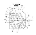
図1は、この発明の圧縮機の一実施形態である簡略構成図を示している。図1に示すように、この圧縮機は、中心軸1aまわりに回転すると共に外周面に中心軸1aまわりに螺旋状に延びる少なくとも1つの溝部10を有する円筒状のスクリューロータ1と、中心軸2aまわりに回転すると共に外周に周方向に配列される複数の歯部20を有する円盤状のゲートロータ2とを有し、上記スクリューロータ1の溝部10と上記ゲートロータ2の歯部20とが噛み合って圧縮室30を形成する。
FIG. 1 shows a simplified configuration diagram as an embodiment of the compressor of the present invention. As shown in FIG. 1, the compressor includes a
つまり、この圧縮機は、いわゆる、CP型のシングルスクリュー圧縮機である。「CP型」とは、上記スクリューロータ1がシリンダ状に形成され、かつ、上記ゲートロータ2がプレート状に形成されていることをいう。この圧縮機は、例えば空気調和機や冷蔵庫等に用いられる。
That is, this compressor is a so-called CP type single screw compressor. “CP type” means that the
上記ゲートロータ2は、上記スクリューロータ中心軸1aを中心として、上記スクリューロータ1の両側に、二つ配設されている。そして、上記スクリューロータ1が、上記スクリューロータ中心軸1aまわりを矢印方向に回転すると、上記溝部10と上記歯部20との噛み合いによって、上記ゲートロータ2は、追従して上記ゲートロータ中心軸2aまわりを矢印方向に回転する。
Two
上記スクリューロータ1の外周面には、上記スクリューロータ中心軸1aのまわりに螺旋状に延びる少なくとも1つのねじ山12が設けられ、上記隣り合うねじ山12,12の間に、上記溝部10が形成される。一つの上記溝部10には、一つの上記歯部20が噛み合い、上記溝部10の側面11に、上記歯部20の側面(つまり、シール部)が接触して、上記圧縮室30をシールしつつ、上記歯部20が、上記溝部10の上記側面11によって、回転される。
At least one
上記スクリューロータ1の外周面には、上記ゲートロータ2の回転が可能なスリットを有する(図示しない)ケーシングが取り付けられている。上記溝部10、上記歯部20および上記ケーシングによって閉塞された空間が、上記圧縮室30となる。
A casing (not shown) having a slit capable of rotating the
上記ケーシングには、上記スクリューロータ1の軸方向一端面側で上記溝部10に連通する(図示しない)吸入ポートが設けられている。上記ケーシングには、上記スクリューロータ1の軸方向他端面側で上記溝部10に連通する(図示しない)吐出ポートが設けられている。
The casing is provided with a suction port (not shown) that communicates with the
この圧縮機の作用を説明すると、上記吸入ポートから上記溝部10に導入された冷媒ガスなどの流体は、上記スクリューロータ1および上記ゲートロータ2の回転によって上記圧縮室30の容積が縮小されることで、上記圧縮室30で圧縮される。そして、圧縮された流体は、上記吐出ポートから吐出される。
Explaining the operation of the compressor, the volume of the
図2の簡略正面図に示すように、上記スクリューロータ中心軸1aを含む第1の平面S1と、上記スクリューロータ中心軸1aに直交すると共に上記スクリューロータ1の溝部10に交差する第2の平面S2と、上記第1の平面S1および上記第2の平面S2に直交すると共に上記スクリューロータ1の溝部10から離隔する第3の平面S3(図4参照)とを定義する。
As shown in the simplified front view of FIG. 2, a first plane S1 including the screw rotor
上記ゲートロータ中心軸2aは、上記第3の平面S3上にあり、上記第1の平面S1、上記第2の平面S2および上記第3の平面S3の交点Pを通る。
The gate rotor
上記ゲートロータ中心軸2aは、上記第3の平面S3に直交する方向からみて、上記第2の平面S2に対して、上記スクリューロータ1の溝部10と同じ側に傾いている。上記ゲートロータ中心軸2aの上記第2の平面S2に対する傾き角度αは、5°〜30°が好ましい。
The gate rotor
ここで、「同じ側に傾く」とは、上記第3の平面S3に直交する方向からみて、上記スクリューロータ1の溝部10の上記第2の平面S2に対する傾きと、上記ゲートロータ中心軸2aの上記第2の平面S2に対する傾きとが、上記第2の平面S2に対して同じ側であることをいう。
Here, “inclined to the same side” means the inclination of the
図3の簡略側面図に示すように、上記ゲートロータ中心軸2aと上記スクリューロータ中心軸1aとの間の距離L(以下、軸間距離Lという)は、例えば、上記ゲートロータ2の外径Dの0.7〜1.2倍である(0.7D≦L≦1.2D)。
As shown in the simplified side view of FIG. 3, the distance L between the gate rotor
図4の拡大平面図に示すように、上記ゲートロータ中心軸2aに直交すると共に全ての上記歯部20を含む平面において、上記溝部10に噛み合っている上記歯部20の中心線が、上記スクリューロータ中心軸1aに平行である基準線に対して、成す角度を、ゲートロータ噛み合い角度γといい、このゲートロータ噛み合い角度γは、上記ゲートロータ2の噛み合い始め側から、計られる。
As shown in the enlarged plan view of FIG. 4, the center line of the
図4に、上記ゲートロータ2の歯部20において、上記スクリューロータ1の溝部10に噛み合う部分の、上記ゲートロータ2の噛み合い最小径、中間径および最大径を示す。また、上記歯部20において、上記ゲートロータ2の回転方向下流側の側面を、リーディング側側面20aとし、上記ゲートロータ2の回転方向上流側の側面を、アンリーディング側側面20bとする。
FIG. 4 shows the minimum meshing diameter, the intermediate diameter, and the maximum diameter of the
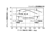
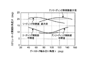
次に、図5〜図8に、上記ゲートロータ中心軸2aの傾き角度α(図2参照)を0°、2.5°、5°、7.5°と変化したときの、ゲートロータ噛み合い角度γ(図4参照)とスクリューロータ溝傾斜角度βとの関係を示す。上記リーディング側側面20aおよび上記アンリーディング側側面20b(図4参照)のそれぞれの上記ゲートロータ2の噛み合い最大径および中間径(図4参照)について、示す。上記スクリューロータ1の溝部10の数量は、3個で、上記ゲートロータ2の歯部20の数量は、12個である。
Next, in FIGS. 5 to 8, the gate rotor meshing when the inclination angle α (see FIG. 2) of the gate rotor
ここで、スクリューロータ溝傾斜角度βとは、図13に示すように、上記スクリューロータ1の溝部10の側面11と接触する部分における(矢印RGにて示す)上記ゲートロータ2の回転方向(つまり、上記ゲートロータ2周方向)と直交する平面Stに対する上記スクリューロータ1の溝部10の側面11の角度βをいう。なお、上記スクリューロータ溝傾斜角度βを、上記平面Stを基準として、ゲートロータ回転方向(矢印RG方向)側を、正の値(+方向)で示し、ゲートロータ回転方向(矢印RG方向)の反対側を、負の値(−方向)で示す。
Here, as shown in FIG. 13, the screw rotor groove inclination angle β is the rotation direction of the gate rotor 2 (indicated by an arrow RG) at a portion in contact with the
図5は、上記ゲートロータ中心軸2aの傾き角度αが0°であるときを示し、上記リーディング側側面20aおよび上記アンリーディング側側面20bのそれぞれの上記ゲートロータ2の噛み合い最大径および中間径について、スクリューロータ溝傾斜角度βの変化幅を表している。
FIG. 5 shows a case where the inclination angle α of the gate rotor
図6は、上記ゲートロータ中心軸2aの傾き角度αが2.5°であるときを示し、図5に示すスクリューロータ溝傾斜角度βの変化幅よりも、スクリューロータ溝傾斜角度βの変化幅が小さくなっている。
6 shows a case where the inclination angle α of the gate rotor
図7は、上記ゲートロータ中心軸2aの傾き角度が5°であるときを示し、上記ゲートロータ噛み合い角度γが大きくなるに従って、上記リーディング側側面20aのスクリューロータ溝傾斜角度βは、小さくなる一方、上記アンリーディング側側面20bのスクリューロータ溝傾斜角度βは、大きくなって、ブローホールを小さくできる構成になっている。
FIG. 7 shows a case where the inclination angle of the gate rotor
図8は、上記ゲートロータ中心軸2aの傾き角度が7.5°であるときを示し、上記ゲートロータ噛み合い角度γが大きくなるに従って、上記リーディング側側面20aのスクリューロータ溝傾斜角度βは、図7に比べて顕著に小さくなる一方、上記アンリーディング側側面20bのスクリューロータ溝傾斜角度βは、図7に比べて顕著に大きくなって、ブローホールを一層小さくできる構成になっている。
FIG. 8 shows a case where the inclination angle of the gate rotor
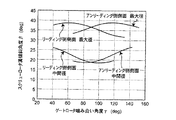
次に、図9〜図12に、上記ゲートロータ中心軸2aの傾き角度α(図2参照)を0°、5°、10°、15°と変化したときの、ゲートロータ噛み合い角度γ(図4参照)とスクリューロータ溝傾斜角度βとの関係を示す。上記リーディング側側面20aおよび上記アンリーディング側側面20b(図4参照)のそれぞれの上記ゲートロータ2の噛み合い最大径および中間径(図4参照)について、示す。この計算例では、上記スクリューロータ1の溝部10の数量は、6個で、上記ゲートロータ2の歯部20の数量は、12個である。
Next, FIGS. 9 to 12 show the gate rotor meshing angle γ (see FIG. 9) when the inclination angle α (see FIG. 2) of the gate rotor
図9は、上記ゲートロータ中心軸2aの傾き角度αが0°であるときを示し、上記リーディング側側面20aおよび上記アンリーディング側側面20bのそれぞれの上記ゲートロータ2の噛み合い最大径および中間径について、スクリューロータ溝傾斜角度βの変化幅が大きくなっている。
FIG. 9 shows the case where the inclination angle α of the gate rotor
図10は、上記ゲートロータ中心軸2aの傾き角度αが5°であるときを示し、図9に示すスクリューロータ溝傾斜角度βの変化幅よりも、スクリューロータ溝傾斜角度βの変化幅が小さくなっている。
FIG. 10 shows the case where the inclination angle α of the gate rotor
図11は、上記ゲートロータ中心軸2aの傾き角度が10°であるときを示し、上記ゲートロータ噛み合い角度γが大きくなるに従って、上記リーディング側側面20aのスクリューロータ溝傾斜角度βは、小さくなる一方、上記アンリーディング側側面20bのスクリューロータ溝傾斜角度βは、大きくなって、ブローホールを小さくできる構成になっている。
FIG. 11 shows a case where the inclination angle of the gate rotor
図12は、上記ゲートロータ中心軸2aの傾き角度が15°であるときを示し、上記ゲートロータ噛み合い角度γが大きくなるに従って、上記リーディング側側面20aのスクリューロータ溝傾斜角度βは、図11に比べて顕著に小さくなる一方、上記アンリーディング側側面20bのスクリューロータ溝傾斜角度βは、図11に比べて顕著に大きくなって、ブローホールを一層小さくできる構成になっている。
FIG. 12 shows a case where the inclination angle of the gate rotor
図13の拡大断面図に示すように、上記ゲートロータ2の歯部20における上記スクリューロータ1の溝部10に接触するシール部21a,21bは、曲面状に形成されている。
As shown in the enlarged sectional view of FIG. 13, the
つまり、上記歯部20のリーディング側側面20aに、リーディング側シール部21aが形成され、上記歯部20のアンリーディング側側面20bに、アンリーディング側シール部21bが形成されている。
That is, the leading side seal portion 21 a is formed on the leading
上記スクリューロータ1は、下向きの矢印方向に、移動し、上記ゲートロータ2は、左向きの矢印方向に、移動する。
The
上記スクリューロータ1の溝部10と上記ゲートロータ2の歯部20との噛み合い部に、ハッチングにて示すブローホール(漏れ隙間)40,50が存在する。
Blow holes (leakage gaps) 40 and 50 indicated by hatching exist in the meshing portion between the
つまり、上記リーディング側シール部21aよりも、上記スクリューロータ1の移動方向上流側(ハッチングにて示す上記圧縮室30側)に、(ハッチングにて示す)リーディング側ブローホール40が存在し、上記アンリーディング側シール部21bよりも、上記スクリューロータ1の移動方向上流側(上記圧縮室30側)に、(ハッチングにて示す)アンリーディング側ブローホール50が存在する。
That is, the leading side blow hole 40 (shown by hatching) is present on the upstream side of the
上記圧縮室30にて圧縮される流体が、上記ブローホール40,50を通って、(仮想線に示す)上記ケーシング3の外側に漏れ出す。
The fluid compressed in the
そして、図14と図15に、上記ゲートロータ中心軸2aの傾き角度α(図2参照)と、漏れ影響度との関係を示す。上記リーディング側ブローホール40(図13参照)の漏れ影響度、上記アンリーディング側ブローホール50(図13参照)の漏れ影響度、および、上記リーディング側ブローホール40と上記アンリーディング側ブローホール50とを合計した漏れ影響度について、示す。ここで、漏れ影響度とは、上記リーディング側ブローホール40および上記アンリーディング側ブローホール50のそれぞれの面積を漏れ量に補正し、上記ゲートロータ中心軸2aの傾き角度αが(従来と同じ)0°であるときを100としたときの度合いを示す。
14 and 15 show the relationship between the inclination angle α (see FIG. 2) of the gate rotor
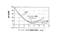
図14は、上記スクリューロータ1の溝部10の数量が3個で、上記ゲートロータ2の歯部20の数量が12個であるときの漏れ影響度を示す。上記ゲートロータ中心軸2aの傾き角度αが7°辺りで、漏れ影響度が極小となっており、圧縮効率が向上する。
FIG. 14 shows the degree of leakage influence when the number of the
図15は、上記スクリューロータ1の溝部10の数量が6個で、上記ゲートロータ2の歯部20の数量が12個であるときの漏れ影響度を示す。上記ゲートロータ中心軸2aの傾き角度αが16°辺りで、漏れ影響度が極小となっており、圧縮効率が向上する。
FIG. 15 shows the degree of leakage influence when the number of the
上記構成の圧縮機によれば、上記ゲートロータ中心軸2aは、上記第1の平面S1、上記第2の平面S2および上記第3の平面S3の交点Pを通ると共に、上記第3の平面S3に直交する方向からみて、上記第2の平面S2に対して、上記スクリューロータ1の溝部10と同じ側に傾いているので、上記ゲートロータ2の歯部20と接触する上記スクリューロータ1の溝部10の側面を、図13に示すように、上記スクリューロータ1の溝部10の側面11に接触する上記ゲートロータ2の歯部20の(矢印RG似て示す)回転方向(つまり、上記ゲートロータ2周方向)に対して、略90°にできて、上記スクリューロータ溝傾斜角度βの変化幅を、小さくできる。
According to the compressor having the above configuration, the gate rotor
言い換えると、上記ゲートロータ2の歯部20と接触する上記スクリューロータ1の溝部10の側面11の上記ゲートロータ2周方向に対する傾斜角度における上記スクリューロータ1の軸方向一端から他端までの変化幅を、上記ゲートロータ中心軸2aが上記スクリューロータ中心軸1aに直交する第2の平面S2に対して平行であるときの変化幅に比べて、小さくしている。なお、「ゲートロータ2周方向」とは、言い換えると、上記スクリューロータ1の溝部10の側面11に接触する上記ゲートロータ2の歯部20の回転方向である。また、「スクリューロータ1の径方向外側から内側までの変化幅」とは、上記ゲートロータ2の歯部20に同時に接触する上記スクリューロータ1の径方向外側から内側まで全ての上記溝部10の傾斜角度の変化幅をいう。
In other words, the change width from one axial end to the other end of the
したがって、上記スクリューロータ1の溝部10の側面と噛み合う上記ゲートロータ2のシール部分のエッジ角度δ1,δ2(図13参照)を鈍くできて、上記スクリューロータ1の溝部10と上記ゲートロータ2の歯部20との噛み合い部に存在するブローホール(漏れ隙間)を小さくできて、圧縮効率を向上できる。また、上記ゲートロータ2のシール部分の摩耗を低減できて、耐久性の向上が図れる。
Accordingly, the edge angles δ1 and δ2 (see FIG. 13) of the seal portion of the
つまり、本発明では、CP型シングルスクリュー圧縮機において、上記ゲートロータ2の歯部20と接触する上記スクリューロータ1の溝部10の側面の角度は、上記ゲートロータ中心軸2aを上記スクリューロータ中心軸1aに直交する平面に対して傾けることにより、変化するということを見出した。
In other words, in the present invention, in the CP type single screw compressor, the angle of the side surface of the
また、上記ゲートロータ中心軸2aの傾き角度αは、5°〜30°が好ましく、上記スクリューロータ溝傾斜角度βの変化幅を一層小さくできる。
In addition, the inclination angle α of the gate rotor
また、上記ゲートロータ2の歯部20における上記スクリューロータ1の溝部10に接触するシール部21a,21bは、曲面状に形成されているので、上記ゲートロータ2の歯部20と上記スクリューロータ1の溝部10との噛み合い部分からの圧縮流体の漏れを減らすことができて、圧縮性能を向上できる。また、上記ゲートロータ2の歯部20と上記スクリューロータ1の溝部10との噛み合い部分の耐摩耗性を向上できる。
Further, since the
言い換えると、上記スクリューロータ溝傾斜角度βの振れ幅を小さくできるので、上記ゲートロータ2の上記シール部21a,21bを曲面状に形成できる。具体的に述べると、エンドミルにより上記スクリューロータ1の溝部10を加工し、エンドミルにより上記ゲートロータ2の歯部20のシール部21a,21bを曲面状に形成して、上記傾斜角度の最大値および最小値に対応できる。
In other words, since the swing width of the screw rotor groove inclination angle β can be reduced, the
なお、この発明は上述の実施形態に限定されない。例えば、上記ゲートロータ2の数量の増減は自由である。また、上記ゲートロータ2の歯部20における上記スクリューロータ1の溝部10に接触するシール部21a,21bは、鋭角状に形成されていてもよい。
In addition, this invention is not limited to the above-mentioned embodiment. For example, the amount of the
1 スクリューロータ
1a スクリューロータ中心軸
10 溝部
11 側面
12 ねじ山
2 ゲートロータ
2a ゲートロータ中心軸
20 歯部
20a リーディング側側面
20b アンリーディング側側面
21a リーディング側シール部
21b アンリーディング側シール部
3 ケーシング
30 圧縮室
40 リーディング側ブローホール
50 アンリーディング側ブローホール
S1 第1の平面
S2 第2の平面
S3 第3の平面
P 交点
D ゲートロータ外径
L 軸間距離
α ゲートロータ中心軸傾き角度
β スクリューロータ溝傾斜角度
γ ゲートロータ噛み合い角度
δ1,δ2 エッジ角度
DESCRIPTION OF
Claims (2)
上記スクリューロータ中心軸(1a)を含む第1の平面(S1)と、上記スクリューロータ中心軸(1a)に直交すると共に上記スクリューロータ(1)の溝部(10)に交差する第2の平面(S2)と、上記第1の平面(S1)および上記第2の平面(S2)に直交すると共に上記スクリューロータ(1)の溝部(10)から離隔する第3の平面(S3)とに関して、
上記ゲートロータ中心軸(2a)は、上記第1の平面(S1)、上記第2の平面(S2)および上記第3の平面(S3)の交点(P)を通ると共に、上記第3の平面(S3)に直交する方向からみて、上記第2の平面(S2)に対して、上記スクリューロータ(1)の溝部(10)と同じ側に傾いており、
上記スクリューロータ(1)の溝部(10)の数量が3個であり、上記ゲートロータ(2)の歯部(20)の数量が12個であって、
上記第3の平面(S3)に直交する方向からみて、上記ゲートロータ中心軸(2a)は、上記第2の平面(S2)に対して、略7°で傾いており、
上記ゲートロータ(2)の歯部(20)における上記スクリューロータ(1)の溝部(10)に接触するシール部(21a,21b)は、曲面状に形成されていることを特徴とする圧縮機。 A cylindrical screw rotor (1) having at least one groove (10) rotating around the central axis (1a) and rotating around the central axis (1a) around the central axis (1a), and around the central axis (2a) A gate rotor (2) having a plurality of teeth (20) that rotate and circumferentially arranged on the outer periphery, and the grooves (10) of the screw rotor (1) and the teeth of the gate rotor (2) In the compressor in which the part (20) meshes to form the compression chamber (30),
A first plane (S1) including the screw rotor central axis (1a), and a second plane (which intersects with the groove (10) of the screw rotor (1) and is orthogonal to the screw rotor central axis (1a) ( S2) and a third plane (S3) perpendicular to the first plane (S1) and the second plane (S2) and spaced from the groove (10) of the screw rotor (1).
The gate rotor central axis (2a) passes through the intersection (P) of the first plane (S1), the second plane (S2), and the third plane (S3), and the third plane. As viewed from the direction orthogonal to (S3), the second plane (S2) is inclined to the same side as the groove (10) of the screw rotor (1) ,
The number of grooves (10) of the screw rotor (1) is 3, and the number of teeth (20) of the gate rotor (2) is 12,
When viewed from the direction orthogonal to the third plane (S3), the gate rotor central axis (2a) is inclined at approximately 7 ° with respect to the second plane (S2).
The compressor is characterized in that seal portions (21a, 21b) in contact with the groove portion (10) of the screw rotor (1) in the tooth portion (20) of the gate rotor (2) are formed in a curved surface shape. .
上記スクリューロータ中心軸(1a)を含む第1の平面(S1)と、上記スクリューロータ中心軸(1a)に直交すると共に上記スクリューロータ(1)の溝部(10)に交差する第2の平面(S2)と、上記第1の平面(S1)および上記第2の平面(S2)に直交すると共に上記スクリューロータ(1)の溝部(10)から離隔する第3の平面(S3)とに関して、
上記ゲートロータ中心軸(2a)は、上記第1の平面(S1)、上記第2の平面(S2)および上記第3の平面(S3)の交点(P)を通ると共に、上記第3の平面(S3)に直交する方向からみて、上記第2の平面(S2)に対して、上記スクリューロータ(1)の溝部(10)と同じ側に傾いており、
上記スクリューロータ(1)の溝部(10)の数量が6個であり、上記ゲートロータ(2)の歯部(20)の数量が12個であって、
上記第3の平面(S3)に直交する方向からみて、上記ゲートロータ中心軸(2a)は、上記第2の平面(S2)に対して、略16°で傾いており、
上記ゲートロータ(2)の歯部(20)における上記スクリューロータ(1)の溝部(10)に接触するシール部(21a,21b)は、曲面状に形成されていることを特徴とする圧縮機。 A cylindrical screw rotor (1) having at least one groove (10) rotating around the central axis (1a) and rotating around the central axis (1a) around the central axis (1a), and around the central axis (2a) A gate rotor (2) having a plurality of teeth (20) that rotate and circumferentially arranged on the outer periphery, and the grooves (10) of the screw rotor (1) and the teeth of the gate rotor (2) In the compressor in which the part (20) meshes to form the compression chamber (30),
A first plane (S1) including the screw rotor central axis (1a), and a second plane (which intersects with the groove (10) of the screw rotor (1) and is orthogonal to the screw rotor central axis (1a) ( S2) and a third plane (S3) perpendicular to the first plane (S1) and the second plane (S2) and spaced from the groove (10) of the screw rotor (1).
The gate rotor central axis (2a) passes through the intersection (P) of the first plane (S1), the second plane (S2), and the third plane (S3), and the third plane. As viewed from the direction orthogonal to (S3), the second plane (S2) is inclined to the same side as the groove (10) of the screw rotor (1) ,
The number of grooves (10) of the screw rotor (1) is 6, and the number of teeth (20) of the gate rotor (2) is 12,
When viewed from the direction orthogonal to the third plane (S3), the gate rotor central axis (2a) is inclined at approximately 16 ° with respect to the second plane (S2).
The compressor is characterized in that seal portions (21a, 21b) in contact with the groove portion (10) of the screw rotor (1) in the tooth portion (20) of the gate rotor (2) are formed in a curved surface shape. .
Priority Applications (5)
| Application Number | Priority Date | Filing Date | Title |
|---|---|---|---|
| JP2006316793A JP4169069B2 (en) | 2006-11-24 | 2006-11-24 | Compressor |
| US12/515,517 US8105059B2 (en) | 2006-11-24 | 2007-11-07 | Compressor with screw rotor and gate rotor with inclined gate rotor center axis |
| CN2007800411613A CN101535650B (en) | 2006-11-24 | 2007-11-07 | Compressor |
| EP07831354.1A EP2090784A4 (en) | 2006-11-24 | 2007-11-07 | Compressor |
| PCT/JP2007/071623 WO2008062672A1 (en) | 2006-11-24 | 2007-11-07 | Compressor |
Applications Claiming Priority (1)
| Application Number | Priority Date | Filing Date | Title |
|---|---|---|---|
| JP2006316793A JP4169069B2 (en) | 2006-11-24 | 2006-11-24 | Compressor |
Publications (2)
| Publication Number | Publication Date |
|---|---|
| JP2008128167A JP2008128167A (en) | 2008-06-05 |
| JP4169069B2 true JP4169069B2 (en) | 2008-10-22 |
Family
ID=39429610
Family Applications (1)
| Application Number | Title | Priority Date | Filing Date |
|---|---|---|---|
| JP2006316793A Expired - Fee Related JP4169069B2 (en) | 2006-11-24 | 2006-11-24 | Compressor |
Country Status (5)
| Country | Link |
|---|---|
| US (1) | US8105059B2 (en) |
| EP (1) | EP2090784A4 (en) |
| JP (1) | JP4169069B2 (en) |
| CN (1) | CN101535650B (en) |
| WO (1) | WO2008062672A1 (en) |
Families Citing this family (6)
| Publication number | Priority date | Publication date | Assignee | Title |
|---|---|---|---|---|
| DK1836665T3 (en) | 2004-11-19 | 2013-04-15 | Glaxosmithkline Llc | PROCEDURE FOR SPECIAL CUSTOMIZED DELIVERY OF VARIABLE DOSAGE MEDICINE COMBINATION PRODUCTS FOR INDIVIDUALIZATION OF THERAPIES |
| JP2011038484A (en) * | 2009-08-13 | 2011-02-24 | Mitsui Seiki Kogyo Co Ltd | Structure of surrounding of ridgeline of gate rotor in screw compressor |
| US9057373B2 (en) | 2011-11-22 | 2015-06-16 | Vilter Manufacturing Llc | Single screw compressor with high output |
| CN103122857B (en) * | 2012-09-29 | 2015-11-18 | 苏州利森空调制冷有限公司 | A kind of compression assembly of band screw-like rotor of compressor |
| JP7360065B1 (en) * | 2022-03-28 | 2023-10-12 | ダイキン工業株式会社 | Screw compressor and refrigeration equipment |
| JP7364949B2 (en) | 2022-03-28 | 2023-10-19 | ダイキン工業株式会社 | single screw compressor |
Family Cites Families (11)
| Publication number | Priority date | Publication date | Assignee | Title |
|---|---|---|---|---|
| US1989552A (en) * | 1934-01-03 | 1935-01-29 | Paul E Good | Rotary compressor |
| FR1601531A (en) * | 1968-12-27 | 1970-08-24 | ||
| GB1388537A (en) * | 1973-03-13 | 1975-03-26 | Zimmern B | Rotary positive-displacement machines for compression or expansion of a fluid |
| JPS5755881B2 (en) * | 1973-03-20 | 1982-11-26 | ||
| DE2315503C2 (en) * | 1973-03-28 | 1983-03-31 | Omphale S.A., Puteaux, Hauts-de-Seine | External rotary piston compression or expansion machine |
| US4179250A (en) * | 1977-11-04 | 1979-12-18 | Chicago Pneumatic Tool Company | Thread construction for rotary worm compression-expansion machines |
| FR2444180A1 (en) * | 1978-12-13 | 1980-07-11 | Zimmern Bernard | VOLUMETRIC SCREW AND PINION MACHINES COMPRISING SEVERAL CONTACT AREAS |
| FR2624215B1 (en) * | 1987-12-03 | 1990-05-11 | Zimmern Bernard | FLOATING SPROCKETS FOR HIGH PRESSURE SCREW MACHINE |
| FR2801349B1 (en) * | 1999-10-26 | 2004-12-17 | Zha Shiliang | SINGLE SCREW COMPRESSOR |
| CN1079501C (en) * | 1999-10-26 | 2002-02-20 | 查世樑 | Energy-saving single-bolt compressor |
| CN1532404A (en) * | 2003-03-24 | 2004-09-29 | 朱妙睿 | Coaxial multisection worm type air compressor |
-
2006
- 2006-11-24 JP JP2006316793A patent/JP4169069B2/en not_active Expired - Fee Related
-
2007
- 2007-11-07 EP EP07831354.1A patent/EP2090784A4/en not_active Withdrawn
- 2007-11-07 CN CN2007800411613A patent/CN101535650B/en not_active Expired - Fee Related
- 2007-11-07 US US12/515,517 patent/US8105059B2/en not_active Expired - Fee Related
- 2007-11-07 WO PCT/JP2007/071623 patent/WO2008062672A1/en active Application Filing
Also Published As
| Publication number | Publication date |
|---|---|
| EP2090784A4 (en) | 2014-01-22 |
| US8105059B2 (en) | 2012-01-31 |
| JP2008128167A (en) | 2008-06-05 |
| EP2090784A1 (en) | 2009-08-19 |
| CN101535650A (en) | 2009-09-16 |
| CN101535650B (en) | 2011-08-03 |
| WO2008062672A1 (en) | 2008-05-29 |
| US20100074785A1 (en) | 2010-03-25 |
Similar Documents
| Publication | Publication Date | Title |
|---|---|---|
| JP4169069B2 (en) | Compressor | |
| US6779993B2 (en) | Rotor profile for screw compressors | |
| JP4169068B2 (en) | Compressor | |
| JP2008133763A (en) | Screw fluid machine | |
| US20040037730A1 (en) | Single-screw compressor | |
| US11300135B2 (en) | Variable stator vane and compressor | |
| JP4211871B2 (en) | Screw compressor | |
| JP2003161277A (en) | Multi-stage dry vacuum pump | |
| JP4821660B2 (en) | Single screw compressor | |
| JP2008150982A (en) | Vane rotary compressor | |
| US8038421B2 (en) | Scroll compressor having an allowable angle of rotation | |
| JPS59168292A (en) | Rotary compressor | |
| CN210127943U9 (en) | Screw compressor | |
| US20140294644A1 (en) | Pump | |
| JP2007146659A (en) | Oil-cooling type compressor | |
| JP2008150981A (en) | Vane rotary compressor | |
| GB2537635A (en) | Pump | |
| CN116324172A (en) | Screw compressor and screw rotor | |
| JP2008291681A (en) | Screw compressor | |
| JP2005535827A (en) | Helical screw rotor compressor | |
| JPS61129489A (en) | Screw type fluid machinery | |
| JP2010185431A (en) | Method for reducing leak loss in z screw compressor | |
| KR20170024056A (en) | Pair of co-operating screw rotors | |
| JPWO2004001229A1 (en) | Screw rotor | |
| JP2009103002A (en) | Trochoid pump and manufacturing method thereof |
Legal Events
| Date | Code | Title | Description |
|---|---|---|---|
| TRDD | Decision of grant or rejection written | ||
| A01 | Written decision to grant a patent or to grant a registration (utility model) |
Free format text: JAPANESE INTERMEDIATE CODE: A01 Effective date: 20080715 |
|
| A01 | Written decision to grant a patent or to grant a registration (utility model) |
Free format text: JAPANESE INTERMEDIATE CODE: A01 |
|
| A61 | First payment of annual fees (during grant procedure) |
Free format text: JAPANESE INTERMEDIATE CODE: A61 Effective date: 20080728 |
|
| FPAY | Renewal fee payment (event date is renewal date of database) |
Free format text: PAYMENT UNTIL: 20110815 Year of fee payment: 3 |
|
| FPAY | Renewal fee payment (event date is renewal date of database) |
Free format text: PAYMENT UNTIL: 20110815 Year of fee payment: 3 |
|
| FPAY | Renewal fee payment (event date is renewal date of database) |
Free format text: PAYMENT UNTIL: 20110815 Year of fee payment: 3 |
|
| FPAY | Renewal fee payment (event date is renewal date of database) |
Free format text: PAYMENT UNTIL: 20120815 Year of fee payment: 4 |
|
| FPAY | Renewal fee payment (event date is renewal date of database) |
Free format text: PAYMENT UNTIL: 20120815 Year of fee payment: 4 |
|
| FPAY | Renewal fee payment (event date is renewal date of database) |
Free format text: PAYMENT UNTIL: 20130815 Year of fee payment: 5 |
|
| LAPS | Cancellation because of no payment of annual fees |