EP3187710A1 - Turbine housing and method for manufacturing turbine housing - Google Patents
Turbine housing and method for manufacturing turbine housing Download PDFInfo
- Publication number
- EP3187710A1 EP3187710A1 EP14905421.5A EP14905421A EP3187710A1 EP 3187710 A1 EP3187710 A1 EP 3187710A1 EP 14905421 A EP14905421 A EP 14905421A EP 3187710 A1 EP3187710 A1 EP 3187710A1
- Authority
- EP
- European Patent Office
- Prior art keywords
- turbine wheel
- turbine housing
- turbine
- scroll
- path
- Prior art date
- Legal status (The legal status is an assumption and is not a legal conclusion. Google has not performed a legal analysis and makes no representation as to the accuracy of the status listed.)
- Granted
Links
Images







Classifications
-
- F—MECHANICAL ENGINEERING; LIGHTING; HEATING; WEAPONS; BLASTING
- F02—COMBUSTION ENGINES; HOT-GAS OR COMBUSTION-PRODUCT ENGINE PLANTS
- F02B—INTERNAL-COMBUSTION PISTON ENGINES; COMBUSTION ENGINES IN GENERAL
- F02B37/00—Engines characterised by provision of pumps driven at least for part of the time by exhaust
-
- F—MECHANICAL ENGINEERING; LIGHTING; HEATING; WEAPONS; BLASTING
- F01—MACHINES OR ENGINES IN GENERAL; ENGINE PLANTS IN GENERAL; STEAM ENGINES
- F01D—NON-POSITIVE DISPLACEMENT MACHINES OR ENGINES, e.g. STEAM TURBINES
- F01D9/00—Stators
- F01D9/02—Nozzles; Nozzle boxes; Stator blades; Guide conduits, e.g. individual nozzles
- F01D9/026—Scrolls for radial machines or engines
-
- F—MECHANICAL ENGINEERING; LIGHTING; HEATING; WEAPONS; BLASTING
- F02—COMBUSTION ENGINES; HOT-GAS OR COMBUSTION-PRODUCT ENGINE PLANTS
- F02B—INTERNAL-COMBUSTION PISTON ENGINES; COMBUSTION ENGINES IN GENERAL
- F02B39/00—Component parts, details, or accessories relating to, driven charging or scavenging pumps, not provided for in groups F02B33/00 - F02B37/00
-
- F—MECHANICAL ENGINEERING; LIGHTING; HEATING; WEAPONS; BLASTING
- F05—INDEXING SCHEMES RELATING TO ENGINES OR PUMPS IN VARIOUS SUBCLASSES OF CLASSES F01-F04
- F05D—INDEXING SCHEME FOR ASPECTS RELATING TO NON-POSITIVE-DISPLACEMENT MACHINES OR ENGINES, GAS-TURBINES OR JET-PROPULSION PLANTS
- F05D2220/00—Application
- F05D2220/40—Application in turbochargers
-
- F—MECHANICAL ENGINEERING; LIGHTING; HEATING; WEAPONS; BLASTING
- F05—INDEXING SCHEMES RELATING TO ENGINES OR PUMPS IN VARIOUS SUBCLASSES OF CLASSES F01-F04
- F05D—INDEXING SCHEME FOR ASPECTS RELATING TO NON-POSITIVE-DISPLACEMENT MACHINES OR ENGINES, GAS-TURBINES OR JET-PROPULSION PLANTS
- F05D2230/00—Manufacture
- F05D2230/10—Manufacture by removing material
-
- F—MECHANICAL ENGINEERING; LIGHTING; HEATING; WEAPONS; BLASTING
- F05—INDEXING SCHEMES RELATING TO ENGINES OR PUMPS IN VARIOUS SUBCLASSES OF CLASSES F01-F04
- F05D—INDEXING SCHEME FOR ASPECTS RELATING TO NON-POSITIVE-DISPLACEMENT MACHINES OR ENGINES, GAS-TURBINES OR JET-PROPULSION PLANTS
- F05D2230/00—Manufacture
- F05D2230/20—Manufacture essentially without removing material
- F05D2230/21—Manufacture essentially without removing material by casting
-
- F—MECHANICAL ENGINEERING; LIGHTING; HEATING; WEAPONS; BLASTING
- F05—INDEXING SCHEMES RELATING TO ENGINES OR PUMPS IN VARIOUS SUBCLASSES OF CLASSES F01-F04
- F05D—INDEXING SCHEME FOR ASPECTS RELATING TO NON-POSITIVE-DISPLACEMENT MACHINES OR ENGINES, GAS-TURBINES OR JET-PROPULSION PLANTS
- F05D2230/00—Manufacture
- F05D2230/90—Coating; Surface treatment
-
- F—MECHANICAL ENGINEERING; LIGHTING; HEATING; WEAPONS; BLASTING
- F05—INDEXING SCHEMES RELATING TO ENGINES OR PUMPS IN VARIOUS SUBCLASSES OF CLASSES F01-F04
- F05D—INDEXING SCHEME FOR ASPECTS RELATING TO NON-POSITIVE-DISPLACEMENT MACHINES OR ENGINES, GAS-TURBINES OR JET-PROPULSION PLANTS
- F05D2250/00—Geometry
- F05D2250/50—Inlet or outlet
- F05D2250/51—Inlet
-
- F—MECHANICAL ENGINEERING; LIGHTING; HEATING; WEAPONS; BLASTING
- F05—INDEXING SCHEMES RELATING TO ENGINES OR PUMPS IN VARIOUS SUBCLASSES OF CLASSES F01-F04
- F05D—INDEXING SCHEME FOR ASPECTS RELATING TO NON-POSITIVE-DISPLACEMENT MACHINES OR ENGINES, GAS-TURBINES OR JET-PROPULSION PLANTS
- F05D2250/00—Geometry
- F05D2250/70—Shape
- F05D2250/71—Shape curved
-
- F—MECHANICAL ENGINEERING; LIGHTING; HEATING; WEAPONS; BLASTING
- F05—INDEXING SCHEMES RELATING TO ENGINES OR PUMPS IN VARIOUS SUBCLASSES OF CLASSES F01-F04
- F05D—INDEXING SCHEME FOR ASPECTS RELATING TO NON-POSITIVE-DISPLACEMENT MACHINES OR ENGINES, GAS-TURBINES OR JET-PROPULSION PLANTS
- F05D2300/00—Materials; Properties thereof
- F05D2300/50—Intrinsic material properties or characteristics
- F05D2300/516—Surface roughness
-
- Y—GENERAL TAGGING OF NEW TECHNOLOGICAL DEVELOPMENTS; GENERAL TAGGING OF CROSS-SECTIONAL TECHNOLOGIES SPANNING OVER SEVERAL SECTIONS OF THE IPC; TECHNICAL SUBJECTS COVERED BY FORMER USPC CROSS-REFERENCE ART COLLECTIONS [XRACs] AND DIGESTS
- Y02—TECHNOLOGIES OR APPLICATIONS FOR MITIGATION OR ADAPTATION AGAINST CLIMATE CHANGE
- Y02T—CLIMATE CHANGE MITIGATION TECHNOLOGIES RELATED TO TRANSPORTATION
- Y02T10/00—Road transport of goods or passengers
- Y02T10/10—Internal combustion engine [ICE] based vehicles
- Y02T10/12—Improving ICE efficiencies
Definitions
- the present disclosure relates to a turbine housing and a method of producing the turbine housing.
- a turbocharger normally includes a rotary shaft, a turbine wheel disposed on an end side of the rotary shaft, and a compressor wheel disposed on the opposite end side of the rotary shaft.
- the rotary shaft rotates at a high speed in response to exhaust energy of exhaust gas being applied to the turbine wheel, and thereby the compressor wheel disposed on the opposite end side of the rotary shaft compresses intake air.
- An engine equipped with a turbocharger can achieve a high output from a small exhaust amount.
- a turbocharger is mounted to an automobile engine in particular to reduce the size of the engine, in order to improve fuel consumption.
- needs toward turbochargers for an engine of a small exhaust amount have been also increasing, and turbocharges have been reduced in size even further.
- a turbine housing of a turbocharger is normally produced by casting.
- a small turbine housing has a higher surface roughness inside the housing than a large turbine housing. Further, a tongue portion of a small turbine housing is thicker due to the minimum possible thickness in casting. As a result, a small turbine housing has a greater flow resistance of exhaust gas. Moreover, a small turbine housing has greater casting errors than a large turbine housing, which increases variation in performance and flow-rate characteristics between products.
- Patent Document 1 PCT/JP2013/085143
- Patent Document 1 related to a turbine housing with an improved surface roughness inside the housing, which reduces the flow resistance of exhaust gas and improves efficiency of a turbocharger.
- the turbine housing of the earlier application is a casted turbine housing provided with a sheet-metal member forming an inner channel inside the turbine housing, which makes the structure rather complicated.
- the present invention was made under the above described conditions in the related art, and an object of at least one embodiment of the present invention is to provide a turbine housing of a simple structure with a reduced flow resistance of exhaust gas and an improved turbocharger efficiency.
- the turning-processing which includes inserting a tool bit into the turbine housing through the opening part larger than a typical opening and rotating the turbine housing to cut or grind the flow-path surface of the region A, it is possible to reduce the roughness of the flow-path surface inside the turbine housing by a simple method.
- an expression of relative or absolute arrangement such as “in a direction”, “along a direction”, “parallel”, “orthogonal”, “centered”, “concentric” and “coaxial” shall not be construed as indicating only the arrangement in a strict literal sense, but also includes a state where the arrangement is relatively displaced by a tolerance, or by an angle or a distance whereby it is possible to achieve the same function.
- an expression of an equal state such as “same” “equal” and “uniform” shall not be construed as indicating only the state in which the feature is strictly equal, but also includes a state in which there is a tolerance or a difference that can still achieve the same function.
- an expression of a shape such as a rectangular shape or a cylindrical shape shall not be construed as only the geometrically strict shape, but also includes a shape with unevenness or chamfered corners within the range in which the same effect can be achieved.
- FIG. 1 is a cross-sectional view of a turbocharger according to an embodiment of the present invention, taken along the axial direction of the rotational shaft of the turbocharger.
- the turbocharger 1 is, though not particularly limited, a small turbocharger to be mounted to an automobile engine, for instance.
- the turbocharger 1 includes a turbine housing 2 for housing a turbine wheel 5, a compressor housing 3 for housing the compressor wheel 6, and a bearing housing 4 for housing bearing devices 10A, 10B rotatably supporting a rotational shaft 7.
- the turbine wheel 5 is coupled to an end of the rotational shaft 7 and the compressor wheel 6 is coupled to the other end of the rotational shaft 7.
- the turbine wheel 5 includes a hub portion 8 having a truncated conical shape, and a plurality of rotor blades 9 disposed at intervals on the outer peripheral surface of the hub portion 8.
- Exhaust gas G taken into the turbine housing 2 from a non-depicted engine flows through a scroll flow path 12 of an annular shape formed around the turbine wheel 5 before being supplied to the turbine wheel 5.
- Exhaust gas flows into the rotor blades 9 from leading edges 9a and flows out from trailing edges 9b, and further flows through an exhaust flow path 14 along the extending direction of the axis K of the turbine wheel 5 to be discharged outside of the turbine housing 2.
- the compressor wheel 6 connected to the same shaft as the turbine wheel 5 also rotates. Accordingly, supply air compressed by the compressor wheel 6 is supplied to an engine (not depicted).
- FIG. 2 is a partial cross-sectional view of a turbine housing 42 according to an embodiment of the present invention, taken along the axial direction of the turbine wheel of the turbine housing 2.
- FIG. 3 is a cross-sectional view showing the shroud side of the Y1-Y1 cross section in FIG. 2 .
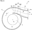
- FIG. 4 is a cross-sectional view showing the hub side of the Y1-Y1 cross section in FIG. 2 .
- FIG. 5 is a cross-sectional view of a typical turbine housing 2', which is a comparative example, corresponding to FIG. 4 .
- FIG. 6 is a diagram showing a modified example of the turbine housing 2 according to an embodiment. FIGs.
- FIG. 7 is each a partial cross-sectional view of the turbine housing 2 according to an embodiment of the present invention, taken along the axial direction of the turbine wheel of the turbine housing 2.
- FIG. 9D is a cross-sectional view showing the hub side of the Y2-Y2 cross section in FIGs. 9A to 9C .
- FIG. 12 is a cross-sectional view of the typical turbine housing 2', which is a comparative example.
- features similar to those of the turbine housing 2 according to an embodiment of the present invention are indicated by the same reference numeral but suffixed with an apostrophe.
- the turbine housing 2 is a turbine housing 2 made by casting.
- the turbine housing 2 includes a scroll part 21, an exhaust duct part 22, and a shroud part 23 formed at a connection section between the scroll part 21 and the exhaust duct part 22.
- the turbine housing 2 includes the scroll part 21, the exhaust duct part 22, and the shroud part 23 formed integrally by casting.
- the turbine housing 2 includes an intake duct part 25 formed integrally by casting at the inlet side of the scroll flow path 12.
- the scroll part 21 forms the scroll flow path 12 of an annular shape for flowing the exhaust gas G around the turbine wheel 5 to be supplied to the turbine wheel 5.
- the scroll part 21 has wall surfaces facing the scroll flow path 12, including: a shroud-side wall surface 21a and a hub-side wall surface 21c extending in a direction orthogonal to the extending direction of the axis K of the turbine wheel 6; and an outer-peripheral-side wall surface 21b extending along the extending direction of the axis K and connecting the shroud-side wall surface 21a and the hub-side wall surface 21c.
- a connection portion 26 to be coupled with the bearing housing 4 via a coupling 27 is formed on the back-face side of the scroll part 21.
- the scroll part 21 has wall surfaces facing the scroll flow path 12, including: a shroud-side wall surface 21a and a hub-side wall surface 21c extending in a direction orthogonal to the extending direction of the axis K of the turbine wheel 5; and an outer-peripheral-side wall surface 21b having an arc shape or a semi-circular shape and connecting the shroud-side wall surface 21a and the hub-side wall surface 21c.
- the shape of the scroll part 21 depicted in FIGs. 2 , 3 , and 6 is a mere example and not to limit the scope of the present invention.
- the shape of the scroll part 21 only needs to be capable of forming the scroll flow path 12 through which the exhaust gas G flows, and may be selected from a variety of shapes.
- the exhaust duct part 22 forms an exhaust flow path 14.
- the exhaust gas G from the turbine wheel 5 flows through the exhaust flow path 14 along the axial direction of the turbine wheel 5.
- a flange portion 24 to be flange-joined to a non-depicted exhaust duct is formed on the front side of the exhaust duct part 22.
- the shroud part 23 is disposed so as to protrude toward the hub at the connection section between the scroll part 21 and the exhaust duct part 22.
- the outer peripheral surface 23a of the shroud part 23 faces the scroll flow path 12, and the inner peripheral surface 23c of the shroud part 23 is formed with a predetermined gap c provided between the inner peripheral surface 23c and outer peripheral edges 9c of the rotor blades 9 of the turbine wheel 5.
- the outer peripheral surface 23a of the shroud part 23 includes an inclined surface inclined from the extending direction of the axis K of the turbine wheel 5, and extends obliquely from a tip 23d of the shroud part 23 toward an inner peripheral edge 21e of the shroud-side wall surface 21a of the scroll part 21.
- a parallel surface 23b is formed between the outer peripheral surface 23a and the inner peripheral surface 23c of the shroud part 23, the parallel surface 23b extending in a direction orthogonal to the extending direction of the axis K of the turbine wheel 5. Further, as depicted in FIG.
- the tip 23d of the shroud part 23 is at a position on the radially outer side of the parallel surface 23b. If the shroud part 23 does not have the parallel surface 23b but has a tip end portion formed into a curved shape, the tip 23d is a portion disposed closest to the hub, as shown in FIG. 6 .
- the turbine housing 2 has an opening part 16 formed on the hub side of the scroll part 21, the opening part 16 having a radius R2 that satisfies a relationship R1 ⁇ R2, provided that R1 is a radial-directional distance from the axis K of the turbine wheel 5 to the tip 23d of the shroud part 23, and R2 is a radial-directional distance from the axis K of the turbine wheel 5 to the inner peripheral edge 21d of the hub-side wall surface 21c of the scroll part 21, in a cross-section taken along the extending direction of the axis K of the turbine wheel 5.
- the roughness of a flow-path surface in a region A is smaller than that in a region B, provided that the region A is a predetermined region from the tip 23d of the shroud part 23 and the region B is a predetermined region adjacent to the region A, among flow-path surfaces 21a, 21b, 21c, 23a of the shroud part 23 and the scroll part 21 facing the scroll flow path 12 at the outer side, in the radial direction, of the tip 23d of the shroud part 23, in a cross section taken along the extending direction of the axis K of the turbine wheel 5.
- the roughness of a flow-path surface can be evaluated by metric average roughness (Ra) specified in JIS B0601-2001, for instance.
- the turbine housing 2 has an opening part 16 formed on the hub side of the scroll part 21, the opening part 16 having a radius R2 that satisfies a relationship R1 ⁇ R2, provided that R1 is a radial-directional distance from the axis K of the turbine wheel 5 to the tip 23d of the shroud part 23, and R2 is a radial-directional distance from the axis K of the turbine wheel 5 to the inner peripheral edge 21d of the hub-side wall surface 21c of the scroll part 21, in a cross-section taken along the extending direction of the axis K of the turbine wheel 5.
- the radius R2' satisfies a relationship R1' ⁇ R2'.
- the radius R2' of the opening part 16 has a relationship R1' ⁇ R2', and thus it is difficult to further process the outer peripheral surface 23a' of the shroud part 23'.
- the turbine housing 2 of the present embodiment it is possible to make use of the opening part 16 which is larger than a typical opening to process a flow-path surface in the region A corresponding to the inner peripheral side of the scroll flow path 12 in particular where the flow rate is high and an influence on the flow resistance is significant, and to reduce the roughness of the flow-path surface, which makes it possible to reduce the flow resistance of the exhaust gas G in the turbine housing 2 and to improve the efficiency of the turbocharger 1.
- the method of processing the flow-path surface of the region A is not particularly limited.
- the method may be machine processing that inserts a tool bit into the casted turbine housing 2 through the opening part 16, and cuts or grinds the flow-path surface of the region A.
- the method may be turning- processing that inserts a tool bit into the casted turbine housing through the opening part 16, and cuts or grinds the flow-path surface of the region A by turning the casted turbine housing 2.
- an existence range of the region A in the radial direction includes at least a part of a range of from 1.15D to 1.4D, provided that D is the outer diameter of the turbine wheel 5.
- the inner diameter at the tip 23d of the shroud part 23 is approximately 1.15D
- the inner diameter at the position of the inner peripheral edge 21e of the shroud-side wall surface 21a of the scroll part 21 is approximately 1.4D. That is, in the depicted embodiment, the range of from 1.15D to 1.4D, the existence range of the region A in the radial direction, is an inclined surface corresponding to the outer peripheral surface 23a of the shroud part 23.
- the region A at least includes the inner peripheral side of the scroll flow path 12 in particular, where the flow rate is high and an influence on the flow resistance is significant. Further, if the outer peripheral surface 23a of the shroud part 23 includes an inclined surface as in the present embodiment, the outer peripheral surface 23a contacts a fluid in a larger contact area, and thus the influence on the flow resistance is even greater.
- the region A formed in the above described range it is possible to reduce the flow resistance of the exhaust gas in the turbine housing 2 and to improve the efficiency of the turbocharger 1.
- the turbine housing 2 further includes a first plate member 40 of an annular shape disposed in the opening part 16 described above, the first plate member 40 having a flow-path portion 40a facing the scroll flow path 12 and a back-face portion 40b disposed with a gap from the back surface of the turbine wheel 5.
- the first plate member 40 has an outer peripheral edge portion 40c which extends in a direction orthogonal to the extending direction of the axis K of the turbine wheel 5, and which is nipped between the turbine housing 2 and the bearing housing 4, whereby the first plate member 40 is fixed inside the turbine housing 2.
- the outer peripheral edge portion 40c is connected to the flow-path portion 40a facing the scroll flow path 12, via a stepped portion 40d extending along the extending direction of the axis K of the turbine wheel 5.
- the flow-path portion 40a extends in a direction orthogonal to the extending direction of the axis K of the turbine wheel 5.
- the back-face portion 40b extends toward the axis K while slightly inclining backward so that a predetermined gap is formed between the back-face portion 40b and the back face of the turbine wheel 5.
- the flow-path portion 40a and the back-face portion 40b have a function to prevent the exhaust gas G from leaking toward the back face of the turbine wheel 5 while the exhaust gas G flows through the scroll flow path 12.
- the first plate member 40 is made from sheet metal. Besides sheet metal, the first plate member 40 may be made by precision casting, or by metal injection molding.
- the first plate member 40 having the flow-path portion 40a facing the scroll flow path 12 in the opening part 16.
- the first plate member 40 is a member separate from the turbine housing 2 made by casting, and the roughness of the surface of the first plate member 40 can be easily set to be smaller than the surface roughness of the turbine housing 2.
- the turbine housing 2 further includes an intake duct part 25 forming an intake flow path 18 for guiding the exhaust gas G taken in from outside of the turbine housing 2 to the scroll flow path 12.
- a tongue portion 50 separating the intake flow path 18 and the scroll flow path 12 is formed by a tongue-portion member 50A provided as a separate member from the turbine housing 2.
- the tongue-portion member 50A extends from the side of the first plate member 40 toward the shroud part 23 as depicted in FIGs. 7 , 8 , 9A , and 9B .
- a tongue portion 50B shorter than the typical tongue portion 50' is formed on the connection section between the intake duct part 25 and the scroll part 21 of the turbine housing 2.
- the tongue-portion member 50A is disposed continuously from the tongue portion 50B of the turbine housing 2, and extends to a rear end position of the typical tongue portion 50'.
- the tongue portion 50 is formed by the tongue-portion member 50A provided separately from the turbine housing 2.
- the tongue portion 50 does not stand in the way of the processing, unlike a case in which the turbine housing 2' made by casting and the tongue portion 50' are formed integrally.
- the inside of the turbine housing 2 can be processed easily.
- the tongue portion 50 is integrally formed with the turbine housing 2 made by casting, it is possible to form the tongue portion 50 to have a smaller thickness. Accordingly, it is possible to suppress flow strain that occurs downstream the tongue portion 50, and thus it is possible to reduce the flow resistance of the exhaust gas G flowing from the intake flow path 18 to the scroll flow path 12.
- the tongue-portion member 50A includes the fourth plate member 48 connected to the flow-path portion 40a of the first plate member 40.
- the fourth plate member 48 is connected to the flow-path portion 40a of the first plate member 40 by welding, for instance.
- the fourth plate member 48 extends along the extending direction of the axis K of the turbine wheel 5, and is in contact with the outer peripheral surface 23a of the shroud part 23 having a tip end portion formed by an inclined surface.
- the fourth plate member 48 is made from sheet metal. Besides sheet metal, the fourth plate member 48 may be made by precision casting, or metal injection molding.
- the tongue portion 50 is formed by the fourth plate member 48 connected to the first plate member 40 by welding or the like, and thereby it is possible to form the tongue portion 50 provided as a separate member from the turbine housing 2 with a simple structure.
- the outer peripheral surface 23a of the shroud part 23 making contact with the tip end portion of the fourth plate member 48 is an inclined surface. Accordingly, the outer peripheral surface 23a can support a force that acts in the radial direction from the radially outer side toward the radially inner side to the fourth plate member 48 due to a pressure difference, and thereby it is possible to prevent oscillation and deformation of the fourth plate member 48 formed to have a small thickness.
- the tongue-portion member 50A is the above described first plate member 40.
- the first plate member 40 has a bend portion 40A made from sheet metal and bended along the extending direction of the axis K of the turbine wheel 5.
- the bend portion 40A forms the tongue portion 50.
- the bend portion 40A is formed by press work, for instance.
- the bend portion 40A extends along the extending direction of the axis K of the turbine wheel 5, and has a tip end portion making contact with the outer peripheral surface 23a, which is an inclined surface, of the shroud part 23.
- the tongue portion 50 is formed by the bend portion 40A of the first plate member 40, and thereby it is possible to form the tongue portion 50 made from sheet metal as a separate member from the turbine housing 2, with a simple structure made of fewer parts.
- the outer peripheral surface 23a of the shroud part 23 making contact with the tip end portion of the bend portion 40A is an inclined surface. Accordingly, the outer peripheral surface 23a can support a force that acts in the radial direction from the radially outer side toward the radially inner side to the bend portion 40A due to a pressure difference, and thereby it is possible to prevent oscillation and deformation of the bend portion 40A of the first plate member made from sheet metal.
- the turbine housing 2 further includes the second plate member 44 disposed so as to cover a part of the flow-path portion 40a of the first plate member 40 in the opening part 16 of the turbine housing 2.
- the above described tongue-portion member 50A is the above described second plate member 44.
- the second plate member 44 has a bend portion 44A made from sheet metal and bended along the axial direction of the turbine wheel 5.
- the bend portion 44A forms the above described tongue portion 50.
- the second plate member 44 has an outer peripheral edge portion 44c which extends in a direction orthogonal to the extending direction of the axis K of the turbine wheel 5, and which is nipped between the turbine housing 2 and the bearing housing 4, whereby the second plate member 44 is fixed inside the turbine housing 2.
- the outer peripheral edge portion 44c is connected to the flow-path portion 44a facing the scroll flow path 12, via a stepped portion 44d extending along the extending direction of the axis K of the turbine wheel 5.
- the flow-path portion 44a extends in a direction orthogonal to the extending direction of the axis K of the turbine wheel 5.
- the flow-path portion 44a covers a part 40a2 of the flow-path portion 40a of the first plate member 40.
- Another part 40a1 which is a remainder after excluding the part 40a2 covered with the flow-path portion44a, directly faces the scroll flow path 12.
- the bend portion 44A extends along the extending direction of the axis K of the turbine wheel 5 from the flow-path portion 44a toward the shroud part 23.
- the bend portion 44A is bended along the extending direction of the axis K of the turbine wheel 5 from the intermediate position of the flow-path portion 44a.
- the flow-path portion 44a is divided into the part 44a1 on the radially outer side and the part 44a2 on the radially inner side across the bend portion 44A.
- the bend portion 44A comprises a folded-back double plate, but is not limited to this. In another embodiment, though not depicted, the bend portion 44A is not folded back and is formed by a single-layer plate.
- the second plate member 44 is made from sheet metal. Besides sheet metal, the second plate member 44 may be made by precision casting, or metal injection molding.
- the tongue portion 50 provided as a separate member from the turbine housing 2 with a simple structure without performing a special processing on the first plate member 40.
- the outer peripheral surface 23a of the shroud part 23 making contact with the tip end portion of the bend portion 44A is an inclined surface. Accordingly, the outer peripheral surface 23a can support a force that acts in the radial direction from the radially outer side toward the radially inner side to the bend portion 44A due to a pressure difference, and thereby it is possible to prevent oscillation and deformation of the bend portion 44A of the second plate member 44 formed to have a small thickness.
- the second plate member 44 includes an annular member extending along the entire periphery in the circumferential direction of the turbine wheel 5.
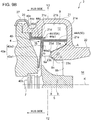
- the flow-path portion 40a1 facing the scroll flow path 12, excluding the part 40a2 of the first plate member 40 covered with the second plate member 44 has the same width rb, in the radial direction, over the entire periphery in the circumferential direction of the turbine wheel 5, as depicted in FIG. 9D .
- the separation distance rb between the inner peripheral edge of the second plate member 44 and the leading edges 9a of the rotor blades 9 is constant over the entire periphery of the turbine wheel 5 in the circumferential direction.
- the flow-path surface of the first plate member 40 is exposed to high-temperature exhaust gas at the width rb, in the radial direction, which is constant over the entire periphery of the turbine wheel 5 in the circumferential direction. Accordingly, it is possible to average the heat input amount to the first plate member 40 in the circumferential direction, and to prevent the first plate member 40 from deforming unevenly due to thermal expansion. Thus, it is possible to prevent an increase in the leakage flow of the exhaust gas G to the back-face side of the turbine wheel 5 due to uneven deformation of the first plate member 40.
- the bearing housing 4 for housing the bearing devices 10A and 10B for rotatably supporting the rotational shaft 7 coupled to the turbine wheel 5.
- the turbine housing 2 further includes the intake duct part 25 forming the intake flow path 18 for guiding the exhaust gas G taken in from outside of the turbine housing 2 to the scroll flow path 12.
- the tongue portion 50 separating the intake flow path 18 and the scroll flow path 12 in the radial direction is formed by a tongue-portion member 50C provided as a separate member from the turbine housing 2.
- the tongue-portion member 50C extends from the bearing housing 4 toward the shroud part 23.
- the turbine housing 2 does not include the above described first plate member 40 and the second plate member 44. Instead, a wall surface 4a of the bearing housing 4 is facing the scroll flow path 12, and is disposed at a gap from the back surface of the turbine wheel 5.
- the tongue portion 50 is formed by the tongue-portion member 50C provided separately from the turbine housing 2.
- the tongue-portion member 50C extends from the bearing housing 4 toward the shroud part 23.
- the above described tongue-portion member 50C includes the third plate member 46 connected to the bearing housing 4.
- the third plate member 46 is connected to the wall surface 4a of the bearing housing 4 by welding, for instance.
- the third plate member 46 extends along the extending direction of the axis K of the turbine wheel 5, and has a tip end portion which makes contact with the outer peripheral surface 23a, which is an inclined surface, of the shroud part 23.
- the third plate member 46 is made from sheet metal. Besides sheet metal, the third plate member 46 may be made by precision casting, or metal injection molding.
- the tongue portion 50 is formed by the third plate member 46 made from sheet metal connected to the wall surface 4a of the bearing housing 4.
- the third plate member 46 is formed as a separate member from the turbine housing 2 made by casting, and thus, as compared to a case in which the tongue portion 50 is integrally formed with the turbine housing 2 made by casting, it is possible to form the tongue portion 50 to have a smaller thickness without difficulty. Accordingly, it is possible to suppress flow strain that occurs downstream the tongue portion 50, and thus it is possible to reduce the flow resistance of exhaust gas flowing from the intake flow path 18 to the scroll flow path 12. Further, it is possible to form the tongue portion 50 with a simple structure of connecting the third plate member 46 to the bearing housing 4.
- the outer peripheral surface 23a of the shroud part 23 making contact with the tip end portion of the third plate member 46 is an inclined surface. Accordingly, the outer peripheral surface 23a can support a force that acts in the radial direction from the radially outer side toward the radially inner side to the third plate member 46 due to a pressure difference, and thereby it is possible to prevent oscillation and deformation of the third plate member 46 made from sheet metal.
- the above described tongue-portion member 50C includes the protruding portion 4A produced integrally with the bearing housing 4 made by casting.
- the protruding portion 4A extends along the extending direction of the axis K of the turbine wheel 5 from the wall surface 4a of the bearing housing 4, and has a tip end portion which makes contact with the outer peripheral surface 23a, which is an inclined surface, of the shroud part 23.
- the tongue portion 50 is formed by the protruding portion 4A integrally produced with the bearing housing 4 made by casting, and thereby it is possible to form the tongue portion 50 as a separate member from the turbine housing 2 with a simple structure.
- a flow-path center 18c of the intake flow path 18 is formed into an S-shaped curve curving outward in the radial direction after curving inward in the radial direction, from the inlet 18a of the intake flow path 18 toward a merging part 18b with the scroll flow path 12.
- the dotted lines show the shape of the intake flow path 18 in the turbine housing 2' of the typical explanatory example depicted in FIG. 5 .
- the tongue portion 50 is formed by a plate member made from sheet metal. If the tongue portion 50 is formed by a plate member of sheet metal, the tongue portion 50 is thin and thus may oscillate in response to a pressure difference between the outer peripheral side and the inner peripheral side of the tongue portion 50, thus increasing the flow resistance. The pressure decreases due to a high-speed exhaust gas flow at the radially inner side of the tongue portion 50, and is lower than the pressure at the outer peripheral side of the tongue portion 50.
- the flow of exhaust gas flowing the radially outer side of the tongue portion 50 can be turned outward, which makes it possible to reduce the pressure at the radially outer side of the tongue portion 50 and to reduce a pressure difference applied to the tongue portion 50.
Landscapes
- Engineering & Computer Science (AREA)
- Mechanical Engineering (AREA)
- General Engineering & Computer Science (AREA)
- Chemical & Material Sciences (AREA)
- Combustion & Propulsion (AREA)
- Supercharger (AREA)
- Turning (AREA)
Description
- The present disclosure relates to a turbine housing and a method of producing the turbine housing.
- As a technique to improve an output of an engine, known is a method which compresses intake air with a turbocharger and supplies an engine with the compressed intake air (supercharging). This method is widely used for automobile engines and the like. A turbocharger normally includes a rotary shaft, a turbine wheel disposed on an end side of the rotary shaft, and a compressor wheel disposed on the opposite end side of the rotary shaft. The rotary shaft rotates at a high speed in response to exhaust energy of exhaust gas being applied to the turbine wheel, and thereby the compressor wheel disposed on the opposite end side of the rotary shaft compresses intake air.
- An engine equipped with a turbocharger can achieve a high output from a small exhaust amount. Thus, in recent years, a turbocharger is mounted to an automobile engine in particular to reduce the size of the engine, in order to improve fuel consumption. In this context, needs toward turbochargers for an engine of a small exhaust amount have been also increasing, and turbocharges have been reduced in size even further.
- A turbine housing of a turbocharger is normally produced by casting. A small turbine housing has a higher surface roughness inside the housing than a large turbine housing. Further, a tongue portion of a small turbine housing is thicker due to the minimum possible thickness in casting. As a result, a small turbine housing has a greater flow resistance of exhaust gas. Moreover, a small turbine housing has greater casting errors than a large turbine housing, which increases variation in performance and flow-rate characteristics between products.
- Patent Document 1:
PCT/JP2013/085143 - Under such a background, the present applicant filed an earlier application (Patent Document 1) related to a turbine housing with an improved surface roughness inside the housing, which reduces the flow resistance of exhaust gas and improves efficiency of a turbocharger. The turbine housing of the earlier application is a casted turbine housing provided with a sheet-metal member forming an inner channel inside the turbine housing, which makes the structure rather complicated.
- The present invention was made under the above described conditions in the related art, and an object of at least one embodiment of the present invention is to provide a turbine housing of a simple structure with a reduced flow resistance of exhaust gas and an improved turbocharger efficiency.
-
- (1) A turbine housing made by casting for housing a turbine wheel configured to rotate by exhaust gas, according to at least one embodiment of the present invention, comprises: a scroll part forming a scroll flow path of an annular shape through which the exhaust gas to be supplied to the turbine wheel flows, around the turbine wheel; an exhaust duct part forming an exhaust flow path through which the exhaust gas having passed through the turbine wheel flows along an axial direction of the turbine wheel; and a shroud part protruding toward a hub at a connection section between the scroll part and the exhaust duct part, the shroud part having an outer peripheral surface facing the scroll flow path and an inner peripheral surface formed at a predetermined gap from rotor blades of the turbine wheel. An opening part is formed on a hub side of the scroll part, the opening part having a radius R2 which satisfies a relationship R1<R2, provided that R1 is a radial directional distance from an axis of the turbine wheel to a tip of the shroud part and R2 is a radial directional distance from the axis of the turbine wheel to an inner peripheral edge of a hub-side wall surface of the scroll part in a cross section taken along the axial direction of the turbine wheel. A roughness of a flow-path surface in a region A is smaller than a roughness of a flow-path surface in a region B, provided that the region A is a predetermined range from the tip of the shroud part and the region B is a predetermined range adjacent to the region A, among flow-path surfaces of the shroud part and the scroll part facing the scroll flow path on an outer side, in a radial direction, of the tip of the shroud part in a cross section taken along the axial direction of the turbine wheel.
In the turbine housing described in the above (1), an opening part is formed on a hub side of the scroll part, the opening part having a radius R2 which satisfies a relationship R1<R2, provided that R1 is a radial directional distance from the axis of the turbine wheel to a tip of the shroud part and R2 is a radial directional distance from the axis of the turbine wheel to an inner peripheral edge of a hub-side wall surface of the scroll part in a cross section taken along the axial direction of the turbine wheel. In contrast, for the opening part 16' of the turbine housing 2' of the typical comparative example illustrated inFIG. 12 , the radius R2' has a relationship R1'≥R2'.
With the turbine housing having a larger opening part than a typical opening, it is possible to work on the inside of the turbine housing after casting by making use of the opening part larger than a typical opening. Accordingly, it is possible to process a flow-path surface in the region A corresponding to the inner peripheral side of the scroll flow path where the flow rate is high and an influence on the flow resistance is significant, and to reduce the roughness of the flow-path surface, which makes it possible to reduce the flow resistance of exhaust gas in the turbine housing and to improve the efficiency of the turbocharger. - (2) In some embodiments, in the turbine housing according to the above (1), an existence range of the region A in the radial direction includes at least a part of a range of from 1.15D to 1.4D, provided that D is an outer diameter of the turbine wheel.
Further, in some embodiments, an existence range of the region A in the radial direction includes at least a part of a range of from 1.20D to 1.4D.
Still further, in some embodiments, an existence range of the region A in the radial direction includes at least a part of a range of from 1.25D to 1.4D.
With the above configuration (2), the region A at least includes the inner peripheral side of the scroll flow path in particular, where the flow rate is high and an influence on the flow resistance is significant. Thus, it possible to reduce the flow resistance of exhaust gas in the turbine housing and to improve the efficiency of the turbocharger. - (3) In some embodiments, in the turbine housing according to the above (1) or (2), an outer peripheral surface of the shroud part includes an inclined surface inclined from the axial direction of the turbine wheel, and the region A includes at least a part of the outer peripheral surface, in a cross section along the axial direction of the turbine wheel.
With the above configuration (3), the region A at least includes an outer peripheral surface of the shroud part disposed on the radially inner side of the scroll flow path in particular, where the flow rate is high and an influence on the flow resistance is significant. Further, if the outer peripheral surface of the shroud part includes an inclined surface, the outer peripheral surface contacts a fluid in a larger contact area, and thus the influence on the flow resistance is even greater. Thus, according to the above embodiment, it possible to reduce the flow resistance of exhaust gas in the turbine housing and to improve the efficiency of the turbocharger. - (4) In some embodiments, the turbine housing according to any one of the above (1) to (3) further comprises a first plate member of an annular shape disposed in the opening part, the first plate member having a flow-path portion facing the scroll flow path and a back-face portion disposed with a gap from a back face of the turbine wheel.
With the above configuration (4), provided in the opening part is the turbine-housing first plate member having the flow-path portion facing the scroll flow path. The first plate member is a member separate from the casted turbine housing, and the roughness of the surface of the first plate member can be easily set to be smaller than the surface roughness of the turbine housing. Thus, according to this embodiment, by reducing the roughness of the flow-path portion of the first plate member facing the scroll flow path, it is possible to reduce the air resistance of exhaust gas flowing through the scroll flow path. - (5) In some embodiments, the turbine housing according to the above (4) further comprises: an intake duct part forming an intake flow path for guiding the exhaust gas taken in from outside the turbine housing to the scroll flow path; and a tongue portion separating the intake flow path and the scroll flow path in the radial direction and being formed by a tongue-portion member provided as a separate member from the turbine housing, the tongue-portion member extending from a side of the first plate member toward the shroud part.
With the above configuration (5), the tongue portion is formed by the tongue-portion member provided separately from the turbine housing. Thus, when the inside of the turbine housing is processed through the opening part after casting, the tongue portion does not interfere with the process, unlike a case in which a casted turbine housing and a tongue portion are formed integrally. Thus, the inside of the turbine housing can be processed easily.
Further, as compared to a case in which a tongue portion is formed integrally with a casted turbine housing, it is possible to form the tongue portion to have a smaller thickness. Accordingly, it is possible to suppress flow strain that occurs downstream the tongue portion, and thus it is possible to reduce the flow resistance of exhaust gas flowing from the intake flow path to the scroll flow path. - (6) In some embodiments, in the turbine housing according to the above (5), the tongue-portion member is the first plate member including a bend portion made from sheet metal and folded along the axial direction of the turbine wheel, the bend portion forming the tongue portion.
According to the above configuration (6), the tongue portion is formed by the bend portion of the first plate member, and thereby it is possible to form the tongue portion made from sheet metal as a separate member from the turbine housing with a simple structure made of fewer parts. - (7) In some embodiments, the turbine housing according to the above (5) further comprises a second plate member disposed so as to cover a part of a flow-path portion of the first plate member in the opening part of the turbine housing. The tongue-portion member includes the second plate member.
With the above configuration (7), the turbine housing further comprises a second plate member disposed so as to cover a part of a flow-path portion of the first plate member. The second plate member forms the tongue portion. According to this embodiment, it is possible to form the tongue portion provided as a separate member from the turbine housing with a simple structure without performing a special processing on the first plate member. - (8) In some embodiments, in the turbine housing according to the above (7), the second plate member has a bend portion made from sheet metal and folded along the axial direction of the turbine wheel. The bend portion forms the tongue portion.
With this configuration (8), it is possible to form a sheet-metal tongue portion provided as a separate member from the turbine housing with a simple structure without performing a special processing on the first plate member. - (9) In some embodiments, in the turbine housing according to the above (7) or (8), the second plate member includes an annular member extending over an entire periphery of the turbine wheel in a circumferential direction, and a flow-path portion facing the scroll flow path excluding a part of the first plate member covered with the second plate member has a radial directional width which is constant over the entire periphery of the turbine wheel in the circumferential direction, in a cross section along the axial direction of the turbine wheel.
With this configuration (9), the flow-path surface of the first plate member is exposed to high-temperature exhaust gas at a constant radial-directional width over the entire periphery of the turbine wheel in the circumferential direction. Accordingly, it is possible to average the heat input amount to the first plate member in the circumferential direction, and to prevent the first plate member from deforming unevenly due to thermal expansion. - (10) In some embodiments, in the turbine housing according to any one of the above (1) to (3), a bearing housing for housing bearing devices rotatably supporting a rotational shaft coupled to the turbine wheel is coupled to a back-face side of the turbine housing. The turbine housing further comprises an intake duct part forming an intake flow path for guiding the exhaust gas taken in from outside the turbine housing to the scroll flow path. A tongue portion separating the intake flow path and the scroll flow path in the radial direction is formed by a tongue-portion member provided as a separate member from the turbine housing, the tongue-portion member extending from the bearing housing toward the shroud part.
With this configuration (10), the tongue portion is formed by the tongue-portion member provided separately from the turbine housing. The tongue-portion member extends from the bearing housing toward the shroud part. Thus, when the inside of the turbine housing is processed through the opening part after casting, the tongue portion does not interfere with the process, unlike a case in which a casted turbine housing and a tongue portion are formed integrally. Thus, the inside of the turbine housing can be processed easily. - (11) In some embodiments, in the turbine housing according to the above (10), the tongue-portion member includes a third plate member connected to the bearing housing.
With this configuration (11), the tongue portion is formed by the third plate member connected to the bearing housing. The third plate member is formed as a separate member from the turbine housing made by casting, and thus, as compared to a case in which a tongue portion is integrally formed with a casted turbine housing, it is possible to form a thin tongue portion without difficulty. Accordingly, it is possible to suppress flow strain that occurs downstream the tongue portion, and thus it is possible to reduce the flow resistance of exhaust gas flowing from the intake flow path to the scroll flow path. Further, it is possible to form the tongue portion with a simple structure of connecting the third plate member to the bearing housing. - (12) In some embodiments, in the turbine housing according to the above (11), the third plate member is made from sheet metal.
With this configuration (12), the third plate member is made from sheet metal, and thus it is possible to form a thin tongue portion with a simple structure. - (13) In some embodiments, in the turbine housing according to any one of claims (5) to (12), the region A is formed to have a radial directional width which is constant over an entire periphery of the turbine wheel in a circumferential direction, in a cross section seen in the axial direction of the turbine wheel.
In the above configurations (5) to (12), the tongue portion is formed by a separate member provided separately from the turbine housing. In contrast, the typical turbine housing 2' depicted inFIG. 5 has a tongue portion 50' integrally formed with the turbine housing 2', and thus the tongue portion 50' makes it difficult to form the region A having a constant radial directional width over the entire periphery of the turbine wheel 5' in the circumferential direction.
With the above configuration (13), the region A is formed to have a constant radial directional width over the entire periphery of the turbine wheel in the circumferential direction, which makes it possible to reduce the flow resistance of exhaust gas over the entire periphery of the turbine wheel in the circumferential direction. - (14) In some embodiments, in the turbine housing according to any one of the above (6), (8), and (12), a flow-path center of the intake flow path is formed into a S-shaped curve curving outward in the radial direction after curving inward in the radial direction, from an inlet part of the intake flow path toward a merging part with the scroll flow path, in a cross section as seen from the axial direction of the turbine wheel.
In the above configurations (6), (8), and (12), the tongue portion is formed by a plate member made from sheet metal. If the tongue portion is to be formed by a plate member of sheet metal, the tongue portion is less thick and may oscillate due to a pressure difference between the outer peripheral side and the inner peripheral side of the tongue portion, thus increasing the flow resistance. Further, a pressure difference applied to the tongue portion may deform the tongue portion. The pressure decreases at the radially inner side of the tongue portion due to a high-speed exhaust gas flow, and is lower than the pressure at the outer peripheral side of the tongue portion.
Thus, with the above configuration (14), with the flow-path center of the intake flow path formed into an S-shape curve, the flow of exhaust gas flowing the radially outer side of the tongue portion can be turned outward, which makes it possible to reduce the pressure at the radially outer side of the tongue portion and to reduce a pressure difference applied to the tongue portion. - (15) A method of producing a turbine housing for housing a turbine wheel configured to rotate by exhaust gas, according to at least one embodiment of the present invention, is for a turbine housing comprising: a scroll part forming a scroll flow path of an annular shape through which the exhaust gas to be supplied to the turbine wheel flows, around the turbine wheel; an exhaust duct part forming an exhaust flow path through which the exhaust gas having passed through the turbine wheel flows along an axial direction of the turbine wheel; and a shroud part protruding toward a hub at a connection section between the scroll part and the exhaust duct part, the shroud part having an outer peripheral surface facing the scroll flow path and an inner peripheral surface formed at a predetermined gap from rotor blades of the turbine wheel. The method comprises: forming an opening part on a hub side of the scroll part, the opening part having a radius R2 which satisfies a relationship R1<R2, provided that R1 is a radial directional distance from an axis of the turbine wheel to a tip of the shroud part and R2 is a radial directional distance from the axis of the turbine wheel to an inner peripheral edge of a hub-side wall surface of the scroll part in a cross section taken along the axial direction of the turbine wheel; and processing a flow-path surface in a region A after casting so that a roughness of the flow-path surface in the region A becomes smaller than a roughness of a flow-path surface in a region B, provided that the region A is a predetermined range from the tip of the shroud part and the region B is a predetermined range adjacent to the region A, among flow-path surfaces of the shroud part and the scroll part facing the scroll flow path on an outer side, in a radial direction, of the tip of the shroud part in a cross section taken along the axial direction of the turbine wheel.
According to the above method of producing a turbine housing (15), it is possible to make use of the larger opening part than a typical opening to work on the inside of the turbine housing after casting, thereby reducing the roughness of the flow-path surface inside the turbine housing. Particularly, it is possible to process a flow-path surface in the region A corresponding to the inner peripheral side of the scroll flow path where the flow rate is high and an influence on the flow resistance is significant, and to reduce the roughness of the flow-path surface, which makes it possible to reduce the flow resistance of exhaust gas in the turbine housing and to improve the efficiency of the turbocharger. - (16) In some embodiments, in the method of producing a turbine housing according to the above (15), the step of processing the flow-path surface of the region A comprises machine processing.
According to the above method (16), it is possible to make use of the larger opening part than a typical opening to work on the inside of the turbine housing after casting by machine processing. Thus, it is possible to reduce the roughness of the flow-path surface inside the turbine housing by a simple method. - (17) In some embodiments, in the method of producing a turbine housing according to the above (16), the step of processing the flow-path surface of the region A comprises turning-processing which includes: inserting a tool bit into the turbine housing made by casting, through the opening part; and rotating the turbine housing made by casting to cut or grind the flow-path surface of the region A.
- According to the above method (17), with the turning-processing which includes inserting a tool bit into the turbine housing through the opening part larger than a typical opening and rotating the turbine housing to cut or grind the flow-path surface of the region A, it is possible to reduce the roughness of the flow-path surface inside the turbine housing by a simple method.
- According to at least one embodiment of the present invention, it is possible to provide a turbine housing of a simple structure with a reduced flow resistance of exhaust gas and an improved turbine efficiency.
-
-
FIG. 1 is a cross-sectional view of a turbocharger according to an embodiment of the present invention, taken along the axial direction of the rotational shaft of the turbocharger. -
FIG. 2 is a partial cross-sectional view of a turbine housing according to an embodiment of the present invention, taken along the axial direction of the turbine wheel of the turbine housing. -
FIG. 3 is a cross-sectional view showing the shroud side of the Y1-Y1 cross section inFIG. 2 . -
FIG. 4 is a cross-sectional view showing the hub side of the Y1-Y1 cross section inFIG. 2 . -
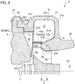
FIG. 5 is a cross-sectional view of a typical turbine housing, which is a comparative example, corresponding toFIG. 4 . -
FIG. 6 is a diagram showing a modified example of a turbine housing according to an embodiment. -
FIG. 7 is a partial cross-sectional view of a turbine housing according to an embodiment of the present invention, taken along the axial direction of the turbine wheel of the turbine housing. -
FIG. 8 is a partial cross-sectional view of a turbine housing according to an embodiment of the present invention, taken along the axial direction of the turbine wheel of the turbine housing. -
FIG. 9A is a partial cross-sectional view of a turbine housing according to an embodiment of the present invention, taken along the axial direction of the turbine wheel of the turbine housing, showing a part in the a-a cross section inFIG. 9D . -
FIG. 9B is a partial cross-sectional view of a turbine housing according to an embodiment of the present invention, taken along the axial direction of the turbine wheel of the turbine housing, showing a part in the b-b cross section inFIG. 9D . -
FIG. 9C is a partial cross-sectional view of a turbine housing according to an embodiment of the present invention, taken along the axial direction of the turbine wheel of the turbine housing, showing a part in the c-c cross section inFIG. 9D . -
FIG. 9D is a cross-sectional view showing the hub side of the Y2-Y2 cross section inFIGs. 9A to 9C . -
FIG. 10 is a partial cross-sectional view of a turbine housing according to an embodiment of the present invention, taken along the axial direction of the turbine wheel of the turbine housing. -
FIG. 11 is a partial cross-sectional view of a turbine housing according to an embodiment of the present invention, taken along the axial direction of the turbine wheel of the turbine housing. -
FIG. 12 is a cross-sectional view of a typical turbine housing, which is a comparative example. - Embodiments of the present invention will now be described in detail with reference to the accompanying drawings. It is intended, however, that unless particularly specified, dimensions, materials, shapes, relative positions and the like of components described in the embodiments shall be interpreted as illustrative only and not intended to limit the scope of the present invention.
- For instance, an expression of relative or absolute arrangement such as "in a direction", "along a direction", "parallel", "orthogonal", "centered", "concentric" and "coaxial" shall not be construed as indicating only the arrangement in a strict literal sense, but also includes a state where the arrangement is relatively displaced by a tolerance, or by an angle or a distance whereby it is possible to achieve the same function.
- For instance, an expression of an equal state such as "same" "equal" and "uniform" shall not be construed as indicating only the state in which the feature is strictly equal, but also includes a state in which there is a tolerance or a difference that can still achieve the same function.
- Further, for instance, an expression of a shape such as a rectangular shape or a cylindrical shape shall not be construed as only the geometrically strict shape, but also includes a shape with unevenness or chamfered corners within the range in which the same effect can be achieved.
- On the other hand, an expression such as "comprise", "include", "have", "contain" and "constitute" are not intended to be exclusive of other components.
-
FIG. 1 is a cross-sectional view of a turbocharger according to an embodiment of the present invention, taken along the axial direction of the rotational shaft of the turbocharger. - The
turbocharger 1 according to an embodiment of the present invention is, though not particularly limited, a small turbocharger to be mounted to an automobile engine, for instance. - As depicted in
FIG. 1 , theturbocharger 1 according to an embodiment of the present invention includes aturbine housing 2 for housing aturbine wheel 5, acompressor housing 3 for housing thecompressor wheel 6, and a bearinghousing 4 forhousing bearing devices rotational shaft 7. Theturbine wheel 5 is coupled to an end of therotational shaft 7 and thecompressor wheel 6 is coupled to the other end of therotational shaft 7. Further, theturbine wheel 5 includes ahub portion 8 having a truncated conical shape, and a plurality ofrotor blades 9 disposed at intervals on the outer peripheral surface of thehub portion 8. - Exhaust gas G taken into the
turbine housing 2 from a non-depicted engine flows through ascroll flow path 12 of an annular shape formed around theturbine wheel 5 before being supplied to theturbine wheel 5. Exhaust gas flows into therotor blades 9 from leadingedges 9a and flows out from trailingedges 9b, and further flows through anexhaust flow path 14 along the extending direction of the axis K of theturbine wheel 5 to be discharged outside of theturbine housing 2. Further, as theturbine wheel 5 rotates in response to the exhaust gas G, thecompressor wheel 6 connected to the same shaft as theturbine wheel 5 also rotates. Accordingly, supply air compressed by thecompressor wheel 6 is supplied to an engine (not depicted). -
FIG. 2 is a partial cross-sectional view of a turbine housing 42 according to an embodiment of the present invention, taken along the axial direction of the turbine wheel of theturbine housing 2.FIG. 3 is a cross-sectional view showing the shroud side of the Y1-Y1 cross section inFIG. 2 .FIG. 4 is a cross-sectional view showing the hub side of the Y1-Y1 cross section inFIG. 2 .FIG. 5 is a cross-sectional view of a typical turbine housing 2', which is a comparative example, corresponding toFIG. 4 .FIG. 6 is a diagram showing a modified example of theturbine housing 2 according to an embodiment.FIGs. 7, 8, 9A to 9C, 10, 11 are each a partial cross-sectional view of theturbine housing 2 according to an embodiment of the present invention, taken along the axial direction of the turbine wheel of theturbine housing 2.FIG. 9D is a cross-sectional view showing the hub side of the Y2-Y2 cross section inFIGs. 9A to 9C .FIG. 12 is a cross-sectional view of the typical turbine housing 2', which is a comparative example. For the turbine housing 2' of the comparative example inFIGs. 5 and12 , features similar to those of theturbine housing 2 according to an embodiment of the present invention are indicated by the same reference numeral but suffixed with an apostrophe. - As depicted in
FIGs. 1 and2 , theturbine housing 2 according to at least one embodiment of the present invention is aturbine housing 2 made by casting. Theturbine housing 2 includes ascroll part 21, anexhaust duct part 22, and ashroud part 23 formed at a connection section between thescroll part 21 and theexhaust duct part 22. In other words, theturbine housing 2 includes thescroll part 21, theexhaust duct part 22, and theshroud part 23 formed integrally by casting. - Further, as depicted in
FIG. 3 , theturbine housing 2 includes anintake duct part 25 formed integrally by casting at the inlet side of thescroll flow path 12. - As depicted in
FIGs. 2 and3 , thescroll part 21 forms thescroll flow path 12 of an annular shape for flowing the exhaust gas G around theturbine wheel 5 to be supplied to theturbine wheel 5. In the depicted embodiment, thescroll part 21 has wall surfaces facing thescroll flow path 12, including: a shroud-side wall surface 21a and a hub-side wall surface 21c extending in a direction orthogonal to the extending direction of the axis K of theturbine wheel 6; and an outer-peripheral-side wall surface 21b extending along the extending direction of the axis K and connecting the shroud-side wall surface 21a and the hub-side wall surface 21c. Further, in the depicted embodiment, aconnection portion 26 to be coupled with the bearinghousing 4 via acoupling 27 is formed on the back-face side of thescroll part 21. - Further, in another embodiment as depicted in
FIG. 6 , thescroll part 21 has wall surfaces facing thescroll flow path 12, including: a shroud-side wall surface 21a and a hub-side wall surface 21c extending in a direction orthogonal to the extending direction of the axis K of theturbine wheel 5; and an outer-peripheral-side wall surface 21b having an arc shape or a semi-circular shape and connecting the shroud-side wall surface 21a and the hub-side wall surface 21c. - The shape of the
scroll part 21 depicted inFIGs. 2 ,3 , and6 is a mere example and not to limit the scope of the present invention. The shape of thescroll part 21 only needs to be capable of forming thescroll flow path 12 through which the exhaust gas G flows, and may be selected from a variety of shapes. - As depicted in
FIGs. 1 and2 , theexhaust duct part 22 forms anexhaust flow path 14. The exhaust gas G from theturbine wheel 5 flows through theexhaust flow path 14 along the axial direction of theturbine wheel 5. In the depicted embodiment, as depicted inFIG. 1 , aflange portion 24 to be flange-joined to a non-depicted exhaust duct is formed on the front side of theexhaust duct part 22. - As depicted in
FIGs. 1 and2 , theshroud part 23 is disposed so as to protrude toward the hub at the connection section between thescroll part 21 and theexhaust duct part 22. The outerperipheral surface 23a of theshroud part 23 faces thescroll flow path 12, and the innerperipheral surface 23c of theshroud part 23 is formed with a predetermined gap c provided between the innerperipheral surface 23c and outerperipheral edges 9c of therotor blades 9 of theturbine wheel 5. - In the depicted embodiment, the outer
peripheral surface 23a of theshroud part 23 includes an inclined surface inclined from the extending direction of the axis K of theturbine wheel 5, and extends obliquely from atip 23d of theshroud part 23 toward an innerperipheral edge 21e of the shroud-side wall surface 21a of thescroll part 21. Further, aparallel surface 23b is formed between the outerperipheral surface 23a and the innerperipheral surface 23c of theshroud part 23, theparallel surface 23b extending in a direction orthogonal to the extending direction of the axis K of theturbine wheel 5. Further, as depicted inFIG. 2 , if theshroud part 23 has theparallel surface 23b, thetip 23d of theshroud part 23 is at a position on the radially outer side of theparallel surface 23b. If theshroud part 23 does not have theparallel surface 23b but has a tip end portion formed into a curved shape, thetip 23d is a portion disposed closest to the hub, as shown inFIG. 6 . - As depicted in
FIGs. 2, 7, 8, 9A to 9C, 10, and 11 , theturbine housing 2 according to at least one embodiment of the present invention has anopening part 16 formed on the hub side of thescroll part 21, the openingpart 16 having a radius R2 that satisfies a relationship R1<R2, provided that R1 is a radial-directional distance from the axis K of theturbine wheel 5 to thetip 23d of theshroud part 23, and R2 is a radial-directional distance from the axis K of theturbine wheel 5 to the innerperipheral edge 21d of the hub-side wall surface 21c of thescroll part 21, in a cross-section taken along the extending direction of the axis K of theturbine wheel 5. Further, the roughness of a flow-path surface in a region A is smaller than that in a region B, provided that the region A is a predetermined region from thetip 23d of theshroud part 23 and the region B is a predetermined region adjacent to the region A, among flow-path surfaces shroud part 23 and thescroll part 21 facing thescroll flow path 12 at the outer side, in the radial direction, of thetip 23d of theshroud part 23, in a cross section taken along the extending direction of the axis K of theturbine wheel 5. The roughness of a flow-path surface can be evaluated by metric average roughness (Ra) specified in JIS B0601-2001, for instance. - The
turbine housing 2 according to the above embodiment has anopening part 16 formed on the hub side of thescroll part 21, the openingpart 16 having a radius R2 that satisfies a relationship R1<R2, provided that R1 is a radial-directional distance from the axis K of theturbine wheel 5 to thetip 23d of theshroud part 23, and R2 is a radial-directional distance from the axis K of theturbine wheel 5 to the innerperipheral edge 21d of the hub-side wall surface 21c of thescroll part 21, in a cross-section taken along the extending direction of the axis K of theturbine wheel 5. - In contrast, for the opening part 16' of the turbine housing 2' of the typical comparative example illustrated in
FIG. 12 , the radius R2' satisfies a relationship R1'≥R2'. In the turbine housing 2' of the comparative example, although theparallel surface 23b' and the innerperipheral surface 23c' (region C) are processed, the radius R2' of theopening part 16 has a relationship R1'≥R2', and thus it is difficult to further process the outerperipheral surface 23a' of the shroud part 23'. - Accordingly, with the
turbine housing 2 of the present embodiment, it is possible to make use of theopening part 16 which is larger than a typical opening to process a flow-path surface in the region A corresponding to the inner peripheral side of thescroll flow path 12 in particular where the flow rate is high and an influence on the flow resistance is significant, and to reduce the roughness of the flow-path surface, which makes it possible to reduce the flow resistance of the exhaust gas G in theturbine housing 2 and to improve the efficiency of theturbocharger 1. - The method of processing the flow-path surface of the region A is not particularly limited. For instance, the method may be machine processing that inserts a tool bit into the
casted turbine housing 2 through the openingpart 16, and cuts or grinds the flow-path surface of the region A. - In some embodiments, the method may be turning- processing that inserts a tool bit into the casted turbine housing through the opening
part 16, and cuts or grinds the flow-path surface of the region A by turning thecasted turbine housing 2. - In some embodiments, as depicted in
FIGs. 2, 7, 8, 9A to 9C, 10, 11 , an existence range of the region A in the radial direction includes at least a part of a range of from 1.15D to 1.4D, provided that D is the outer diameter of theturbine wheel 5. - In the depicted embodiment, the inner diameter at the
tip 23d of theshroud part 23 is approximately 1.15D, and the inner diameter at the position of the innerperipheral edge 21e of the shroud-side wall surface 21a of thescroll part 21 is approximately 1.4D. That is, in the depicted embodiment, the range of from 1.15D to 1.4D, the existence range of the region A in the radial direction, is an inclined surface corresponding to the outerperipheral surface 23a of theshroud part 23. - According to this embodiment, the region A at least includes the inner peripheral side of the
scroll flow path 12 in particular, where the flow rate is high and an influence on the flow resistance is significant. Further, if the outerperipheral surface 23a of theshroud part 23 includes an inclined surface as in the present embodiment, the outerperipheral surface 23a contacts a fluid in a larger contact area, and thus the influence on the flow resistance is even greater. Thus, according to the above embodiment, with the region A formed in the above described range, it is possible to reduce the flow resistance of the exhaust gas in theturbine housing 2 and to improve the efficiency of theturbocharger 1. - In some embodiments, as depicted in
FIGs. 2, 7, 8, and 9A to 9C , theturbine housing 2 further includes afirst plate member 40 of an annular shape disposed in theopening part 16 described above, thefirst plate member 40 having a flow-path portion 40a facing thescroll flow path 12 and a back-face portion 40b disposed with a gap from the back surface of theturbine wheel 5. - In the depicted embodiment, the
first plate member 40 has an outerperipheral edge portion 40c which extends in a direction orthogonal to the extending direction of the axis K of theturbine wheel 5, and which is nipped between theturbine housing 2 and the bearinghousing 4, whereby thefirst plate member 40 is fixed inside theturbine housing 2. The outerperipheral edge portion 40c is connected to the flow-path portion 40a facing thescroll flow path 12, via a steppedportion 40d extending along the extending direction of the axis K of theturbine wheel 5. The flow-path portion 40a extends in a direction orthogonal to the extending direction of the axis K of theturbine wheel 5. The back-face portion 40b extends toward the axis K while slightly inclining backward so that a predetermined gap is formed between the back-face portion 40b and the back face of theturbine wheel 5. The flow-path portion 40a and the back-face portion 40b have a function to prevent the exhaust gas G from leaking toward the back face of theturbine wheel 5 while the exhaust gas G flows through thescroll flow path 12. - In the depicted embodiment, the
first plate member 40 is made from sheet metal. Besides sheet metal, thefirst plate member 40 may be made by precision casting, or by metal injection molding. - In this embodiment, provided is the
first plate member 40 having the flow-path portion 40a facing thescroll flow path 12 in theopening part 16. Thefirst plate member 40 is a member separate from theturbine housing 2 made by casting, and the roughness of the surface of thefirst plate member 40 can be easily set to be smaller than the surface roughness of theturbine housing 2. Thus, according to this embodiment, by reducing the roughness of the flow-path portion 40a of thefirst plate member 40 facing thescroll flow path 12, it is possible to reduce the flow resistance of exhaust gas flowing through thescroll flow path 12. - In some embodiments, as shown in
FIG. 4 , theturbine housing 2 further includes anintake duct part 25 forming anintake flow path 18 for guiding the exhaust gas G taken in from outside of theturbine housing 2 to thescroll flow path 12. Atongue portion 50 separating theintake flow path 18 and thescroll flow path 12 is formed by a tongue-portion member 50A provided as a separate member from theturbine housing 2. The tongue-portion member 50A extends from the side of thefirst plate member 40 toward theshroud part 23 as depicted inFIGs. 7 ,8 ,9A , and9B . - In the embodiment depicted in
FIG. 4 , atongue portion 50B shorter than the typical tongue portion 50' is formed on the connection section between theintake duct part 25 and thescroll part 21 of theturbine housing 2. The tongue-portion member 50A is disposed continuously from thetongue portion 50B of theturbine housing 2, and extends to a rear end position of the typical tongue portion 50'. - According to this embodiment, the
tongue portion 50 is formed by the tongue-portion member 50A provided separately from theturbine housing 2. Thus, when the inside of theturbine housing 2 is processed through the openingpart 16 after casting, thetongue portion 50 does not stand in the way of the processing, unlike a case in which the turbine housing 2' made by casting and the tongue portion 50' are formed integrally. Thus, the inside of theturbine housing 2 can be processed easily. - Further, as compared to a case in which the
tongue portion 50 is integrally formed with theturbine housing 2 made by casting, it is possible to form thetongue portion 50 to have a smaller thickness. Accordingly, it is possible to suppress flow strain that occurs downstream thetongue portion 50, and thus it is possible to reduce the flow resistance of the exhaust gas G flowing from theintake flow path 18 to thescroll flow path 12. - In some embodiments, as depicted in
FIG. 7 , the tongue-portion member 50A includes the fourth plate member 48 connected to the flow-path portion 40a of thefirst plate member 40. The fourth plate member 48 is connected to the flow-path portion 40a of thefirst plate member 40 by welding, for instance. The fourth plate member 48 extends along the extending direction of the axis K of theturbine wheel 5, and is in contact with the outerperipheral surface 23a of theshroud part 23 having a tip end portion formed by an inclined surface. - In the depicted embodiment, the fourth plate member 48 is made from sheet metal. Besides sheet metal, the fourth plate member 48 may be made by precision casting, or metal injection molding.
- According to this embodiment, the
tongue portion 50 is formed by the fourth plate member 48 connected to thefirst plate member 40 by welding or the like, and thereby it is possible to form thetongue portion 50 provided as a separate member from theturbine housing 2 with a simple structure. - The outer
peripheral surface 23a of theshroud part 23 making contact with the tip end portion of the fourth plate member 48 is an inclined surface. Accordingly, the outerperipheral surface 23a can support a force that acts in the radial direction from the radially outer side toward the radially inner side to the fourth plate member 48 due to a pressure difference, and thereby it is possible to prevent oscillation and deformation of the fourth plate member 48 formed to have a small thickness. - In some embodiments, as depicted in
FIG. 8 , the tongue-portion member 50A is the above describedfirst plate member 40. Thefirst plate member 40 has abend portion 40A made from sheet metal and bended along the extending direction of the axis K of theturbine wheel 5. Thebend portion 40A forms thetongue portion 50. Thebend portion 40A is formed by press work, for instance. Thebend portion 40A extends along the extending direction of the axis K of theturbine wheel 5, and has a tip end portion making contact with the outerperipheral surface 23a, which is an inclined surface, of theshroud part 23. - According to this embodiment, the
tongue portion 50 is formed by thebend portion 40A of thefirst plate member 40, and thereby it is possible to form thetongue portion 50 made from sheet metal as a separate member from theturbine housing 2, with a simple structure made of fewer parts. - The outer
peripheral surface 23a of theshroud part 23 making contact with the tip end portion of thebend portion 40A is an inclined surface. Accordingly, the outerperipheral surface 23a can support a force that acts in the radial direction from the radially outer side toward the radially inner side to thebend portion 40A due to a pressure difference, and thereby it is possible to prevent oscillation and deformation of thebend portion 40A of the first plate member made from sheet metal. - In some embodiments, as depicted in
FIGs. 9A to 9C , theturbine housing 2 further includes thesecond plate member 44 disposed so as to cover a part of the flow-path portion 40a of thefirst plate member 40 in theopening part 16 of theturbine housing 2. As depicted inFIGs. 9A and9B , the above described tongue-portion member 50A is the above describedsecond plate member 44. - Further, in some embodiments, as depicted in
FIGs. 9A and9B , thesecond plate member 44 has abend portion 44A made from sheet metal and bended along the axial direction of theturbine wheel 5. Thebend portion 44A forms the above describedtongue portion 50. - In the depicted embodiment, the
second plate member 44 has an outerperipheral edge portion 44c which extends in a direction orthogonal to the extending direction of the axis K of theturbine wheel 5, and which is nipped between theturbine housing 2 and the bearinghousing 4, whereby thesecond plate member 44 is fixed inside theturbine housing 2. The outerperipheral edge portion 44c is connected to the flow-path portion 44a facing thescroll flow path 12, via a steppedportion 44d extending along the extending direction of the axis K of theturbine wheel 5. The flow-path portion 44a extends in a direction orthogonal to the extending direction of the axis K of theturbine wheel 5. The flow-path portion 44a covers a part 40a2 of the flow-path portion 40a of thefirst plate member 40. Another part 40a1, which is a remainder after excluding the part 40a2 covered with the flow-path portion44a, directly faces thescroll flow path 12. Thebend portion 44A extends along the extending direction of the axis K of theturbine wheel 5 from the flow-path portion 44a toward theshroud part 23. - As depicted in
FIGs. 9A and9B , thebend portion 44A is bended along the extending direction of the axis K of theturbine wheel 5 from the intermediate position of the flow-path portion 44a. As depicted inFIG. 9B , the flow-path portion 44a is divided into the part 44a1 on the radially outer side and the part 44a2 on the radially inner side across thebend portion 44A. - In the embodiment depicted in
FIGs. 9A and9B , thebend portion 44A comprises a folded-back double plate, but is not limited to this. In another embodiment, though not depicted, thebend portion 44A is not folded back and is formed by a single-layer plate. - In the depicted embodiment, the
second plate member 44 is made from sheet metal. Besides sheet metal, thesecond plate member 44 may be made by precision casting, or metal injection molding. - According to this embodiment, it is possible to form the
tongue portion 50 provided as a separate member from theturbine housing 2 with a simple structure without performing a special processing on thefirst plate member 40. - The outer
peripheral surface 23a of theshroud part 23 making contact with the tip end portion of thebend portion 44A is an inclined surface. Accordingly, the outerperipheral surface 23a can support a force that acts in the radial direction from the radially outer side toward the radially inner side to thebend portion 44A due to a pressure difference, and thereby it is possible to prevent oscillation and deformation of thebend portion 44A of thesecond plate member 44 formed to have a small thickness. - In some embodiments, as depicted in
FIGs. 9A to 9D , thesecond plate member 44 includes an annular member extending along the entire periphery in the circumferential direction of theturbine wheel 5. As depicted inFIGs. 9A to 9C , in a cross section along the extending direction of the axis K of theturbine wheel 5, the flow-path portion 40a1 facing thescroll flow path 12, excluding the part 40a2 of thefirst plate member 40 covered with thesecond plate member 44, has the same width rb, in the radial direction, over the entire periphery in the circumferential direction of theturbine wheel 5, as depicted inFIG. 9D . In other words, as depicted inFIGs. 9A to 9C , the separation distance rb between the inner peripheral edge of thesecond plate member 44 and theleading edges 9a of therotor blades 9 is constant over the entire periphery of theturbine wheel 5 in the circumferential direction. - According to this embodiment, the flow-path surface of the
first plate member 40 is exposed to high-temperature exhaust gas at the width rb, in the radial direction, which is constant over the entire periphery of theturbine wheel 5 in the circumferential direction. Accordingly, it is possible to average the heat input amount to thefirst plate member 40 in the circumferential direction, and to prevent thefirst plate member 40 from deforming unevenly due to thermal expansion. Thus, it is possible to prevent an increase in the leakage flow of the exhaust gas G to the back-face side of theturbine wheel 5 due to uneven deformation of thefirst plate member 40. - In some embodiments, as depicted in
FIG. 1 , coupled to the back-face side of theturbine housing 2 is the bearinghousing 4 for housing thebearing devices rotational shaft 7 coupled to theturbine wheel 5. As shown inFIG. 4 , theturbine housing 2 further includes theintake duct part 25 forming theintake flow path 18 for guiding the exhaust gas G taken in from outside of theturbine housing 2 to thescroll flow path 12. Further, as depicted inFIGs. 10 and11 , thetongue portion 50 separating theintake flow path 18 and thescroll flow path 12 in the radial direction is formed by a tongue-portion member 50C provided as a separate member from theturbine housing 2. The tongue-portion member 50C extends from the bearinghousing 4 toward theshroud part 23. - In the embodiment depicted in
FIGs. 10 and11 , theturbine housing 2 does not include the above describedfirst plate member 40 and thesecond plate member 44. Instead, awall surface 4a of the bearinghousing 4 is facing thescroll flow path 12, and is disposed at a gap from the back surface of theturbine wheel 5. - According to this embodiment, the
tongue portion 50 is formed by the tongue-portion member 50C provided separately from theturbine housing 2. The tongue-portion member 50C extends from the bearinghousing 4 toward theshroud part 23. Thus, when the inside of theturbine housing 2 is processed through the openingpart 16 after casting, thetongue portion 50 does not interfere with the process, unlike a case in which the turbine housing 2' made by casting and the tongue portion 50' are formed integrally. Thus, the inside of theturbine housing 2 can be processed easily. - In some embodiments, as depicted in
FIG. 10 , the above described tongue-portion member 50C includes thethird plate member 46 connected to the bearinghousing 4. Thethird plate member 46 is connected to thewall surface 4a of the bearinghousing 4 by welding, for instance. Thethird plate member 46 extends along the extending direction of the axis K of theturbine wheel 5, and has a tip end portion which makes contact with the outerperipheral surface 23a, which is an inclined surface, of theshroud part 23. - In the depicted embodiment, the
third plate member 46 is made from sheet metal. Besides sheet metal, thethird plate member 46 may be made by precision casting, or metal injection molding. - According to this embodiment, the
tongue portion 50 is formed by thethird plate member 46 made from sheet metal connected to thewall surface 4a of the bearinghousing 4. Thethird plate member 46 is formed as a separate member from theturbine housing 2 made by casting, and thus, as compared to a case in which thetongue portion 50 is integrally formed with theturbine housing 2 made by casting, it is possible to form thetongue portion 50 to have a smaller thickness without difficulty. Accordingly, it is possible to suppress flow strain that occurs downstream thetongue portion 50, and thus it is possible to reduce the flow resistance of exhaust gas flowing from theintake flow path 18 to thescroll flow path 12. Further, it is possible to form thetongue portion 50 with a simple structure of connecting thethird plate member 46 to the bearinghousing 4. - Moreover, the outer
peripheral surface 23a of theshroud part 23 making contact with the tip end portion of thethird plate member 46 is an inclined surface. Accordingly, the outerperipheral surface 23a can support a force that acts in the radial direction from the radially outer side toward the radially inner side to thethird plate member 46 due to a pressure difference, and thereby it is possible to prevent oscillation and deformation of thethird plate member 46 made from sheet metal. - In some embodiments, as depicted in
FIG. 11 , the above described tongue-portion member 50C includes the protrudingportion 4A produced integrally with the bearinghousing 4 made by casting. The protrudingportion 4A extends along the extending direction of the axis K of theturbine wheel 5 from thewall surface 4a of the bearinghousing 4, and has a tip end portion which makes contact with the outerperipheral surface 23a, which is an inclined surface, of theshroud part 23. - According to this embodiment, the
tongue portion 50 is formed by the protrudingportion 4A integrally produced with the bearinghousing 4 made by casting, and thereby it is possible to form thetongue portion 50 as a separate member from theturbine housing 2 with a simple structure. - In some embodiments, as depicted in
FIGs. 3 ,4 , and9D , in a cross section as seen in the extending direction of the axis K of theturbine wheel 5, a flow-path center 18c of theintake flow path 18 is formed into an S-shaped curve curving outward in the radial direction after curving inward in the radial direction, from theinlet 18a of theintake flow path 18 toward a mergingpart 18b with thescroll flow path 12. InFIGs. 3 ,4 , and9D , the dotted lines show the shape of theintake flow path 18 in the turbine housing 2' of the typical explanatory example depicted inFIG. 5 . - In the embodiments depicted in
FIGs. 7, 8, 9A to 9C, and 10 , thetongue portion 50 is formed by a plate member made from sheet metal. If thetongue portion 50 is formed by a plate member of sheet metal, thetongue portion 50 is thin and thus may oscillate in response to a pressure difference between the outer peripheral side and the inner peripheral side of thetongue portion 50, thus increasing the flow resistance. The pressure decreases due to a high-speed exhaust gas flow at the radially inner side of thetongue portion 50, and is lower than the pressure at the outer peripheral side of thetongue portion 50. - Thus, according to this embodiment, with the flow-
path center 18c of theintake flow path 18 formed into an S-shape curve, the flow of exhaust gas flowing the radially outer side of thetongue portion 50 can be turned outward, which makes it possible to reduce the pressure at the radially outer side of thetongue portion 50 and to reduce a pressure difference applied to thetongue portion 50. - The embodiments of the present invention have been described above. However, the present invention is not limited thereto. For instance, various modifications may be applied as long as they do not depart from the object of the present invention.
-
- 1
- Turbocharger
- 2
- Turbine housing
- 3
- Compressor housing
- 4
- Bearing housing
- 4A
- Protruding portion
- 4a
- Wall surface
- 5
- Turbine wheel
- 6
- Compressor wheel
- 7
- Rotational shaft
- 8
- Hub portion
- 9
- Rotor blade
- 9a
- Leading edge
- 9b
- Trailing edge
- 9c
- Outer peripheral edge
- 10A, 10B
- Bearing device
- 12
- Scroll flow path
- 14
- Exhaust flow path
- 16
- Opening part
- 18
- Intake flow path
- 18a
- Inlet
- 18b
- Merging part
- 18c
- Flow-path center
- 21
- Scroll part
- 21a
- Shroud-side wall surface (flow-path surface)
- 21b
- Outer-peripheral-side wall surface (flow-path surface)
- 21c
- Hub-side wall surface (flow-path surface)
- 21d
- Inner peripheral edge of hub-side wall surface
- 21e
- Inner peripheral edge of shroud-side wall surface
- 22
- Exhaust duct part
- 23
- Shroud part
- 23a
- Outer peripheral surface (flow-path surface)
- 23b
- Parallel surface
- 23c
- Inner peripheral surface
- 23d
- Tip end of shroud part
- 24
- Flange portion
- 25
- Intake duct part
- 26
- Connection portion
- 27
- Coupling
- 40
- First plate member
- 40A
- Bend portion
- 40a
- Flow-path portion
- 40a1
- Portion not covered with second plate member
- 40a2
- Portion covered with second plate member
- 40b
- Back-face portion
- 40c
- Outer peripheral edge portion
- 40d
- Stepped portion
- 44
- Second plate member
- 44A
- Bend portion
- 44a
- Flow-path portion
- 44a1
- Radially-outside flow-path portion
- 44a2
- Radially-inside flow-path portion
- 44c
- Outer peripheral edge portion
- 44d
- Stepped portion
- 46
- Third plate member
- 48
- Fourth plate member
- 50
- Tongue portion
- 50A
- Tongue-portion member
- 50B
- Tongue-portion member
- 50C
- Tongue-portion member
Claims (17)
- A turbine housing (2) made by casting for housing a turbine wheel (5) configured to rotate by exhaust gas, comprising:a scroll part (21) forming a scroll flow path (12) of an annular shape through which the exhaust gas (G) to be supplied to the turbine wheel (5) flows, around the turbine wheel (5);an exhaust duct part (22) forming an exhaust flow path (14) through which the exhaust gas (G) having passed through the turbine wheel (5) flows along an axial direction of the turbine wheel (5); anda shroud part (23) protruding toward a hub at a connection section between the scroll part (21) and the exhaust duct part (22), the shroud part (23) having an outer peripheral surface facing the scroll flow path (12) and an inner peripheral surface formed at a predetermined gap (c) from rotor blades (9) of the turbine wheel (5),wherein, an opening part (16) is formed on a hub side of the scroll part (21), the opening part (16) having a radius R2 which satisfies a relationship R1<R2, provided that R1 is a radial directional distance from an axis (K) of the turbine wheel to a tip (23d) of the shroud part (23) and R2 is a radial directional distance from the axis (K) of the turbine wheel to an inner peripheral edge (21d) of a hub-side wall surface (21c) of the scroll part (21) in a cross section taken along the axial direction of the turbine wheel (5), andwherein a roughness of a flow-path surface in a region A is smaller than a roughness of a flow-path surface in a region B, provided that the region A is a predetermined range from the tip (23d) of the shroud part (23) and the region B is a predetermined range adjacent to the region A, among flow-path surfaces (21a, 21b, 21c, 23a) of the shroud part (23) and the scroll part (21) facing the scroll flow path (12) on an outer side, in a radial direction, of the tip (23d) of the shroud part (23) in a cross section taken along the axial direction of the turbine wheel (3).
- The turbine housing according to claim 1,
wherein an existence range of the region A in the radial direction includes at least a part of a range of from 1.15D to 1.4D, provided that D is an outer diameter of the turbine wheel (5). - The turbine housing according to 1 or 2,
wherein an outer peripheral surface (23a) of the shroud part (23) includes an inclined surface inclined from the axial direction of the turbine wheel, and the region A includes at least a part of the outer peripheral surface (23a), in a cross section along the axial direction of the turbine wheel (5). - The turbine housing according to any one of claims 1 to 3, further comprising a first plate member (40) of an annular shape disposed in the opening part (16), the first plate member (40) having a flow-path portion (40a) facing the scroll flow path (12) and a back-face portion (40b) disposed with a gap from a back face of the turbine wheel (5).
- The turbine housing according to claim 4, further comprising:an intake duct part (25) forming an intake flow path (18) for guiding the exhaust gas (G) taken in from outside the turbine housing (2) to the scroll flow path (12); anda tongue portion (50) separating the intake flow path (18) and the scroll flow path (12) in the radial direction and being formed by a tongue-portion member (50A) provided as a separate member from the turbine housing (2), the tongue-portion member (50A) extending from a side of the first plate member (40) toward the shroud part (23).
- The turbine housing according to claim 5,
wherein the tongue-portion member (50A) is the first plate member (40) including a bend portion (40A) made from sheet metal and folded along the axial direction of the turbine wheel (5), the bend portion (40A) forming the tongue portion (50). - The turbine housing according to claim 5, further comprising a second plate member (50) disposed so as to cover a part of a flow-path portion (40a) of the first plate member (40) in the opening part (16) of the turbine housing (2),
wherein the tongue-portion member (50A) includes the second plate member (44). - The turbine housing according to claim 7,
wherein the second plate member (44) has a bend portion (44A) made from sheet metal and folded along the axial direction of the turbine wheel (5), the bend portion (44A) forming the tongue portion (50). - The turbine housing according to claim 7 or 8,
wherein the second plate member (44) is includes an annular member extending over an entire periphery of the turbine wheel (5) in a circumferential direction, and
wherein a flow-path portion (40a1) facing the scroll flow path (12) excluding a part (40a2) of the first plate member (40) covered with the second plate member (44) has a radial directional width (rb) which is constant over the entire periphery of the turbine wheel (5) in the circumferential direction, in a cross section along the axial direction of the turbine wheel (5). - The turbine housing according to any one of claims 1 to 3,
wherein a bearing housing (4) for housing bearing devices (10A, 10B) rotatably supporting a rotational shaft (7) coupled to the turbine wheel (5) is coupled to a back-face side of the turbine housing (2),
wherein the turbine housing (2) further comprises an intake duct part (25) forming an intake flow path (18) for guiding the exhaust gas (G) taken in from outside the turbine housing (2) to the scroll flow path (12), and
wherein a tongue portion (50) separating the intake flow path (18) and the scroll flow path (12) in the radial direction is formed by a tongue-portion member (50C) provided as a separate member from the turbine housing (2), the tongue-portion member (50C) extending from the bearing housing (4) toward the shroud part (23). - The turbine housing according to claim 10, wherein the tongue-portion member (50C) includes a third plate member (46) connected to the bearing housing (4).
- The turbine housing according to claim 11, wherein the third plate member (46) is made from sheet metal.
- The turbine housing according to any one of claims 5 to 12,
wherein the region A is formed to have a radial directional width (ra) which is constant over an entire periphery of the turbine wheel (5) in a circumferential direction, in a cross section seen in the axial direction of the turbine wheel (5). - The turbine housing according to any one of claims 6, 8, and 12,
wherein a flow-path center (18c) of the intake flow path (18) is formed into a S-shaped curve curving outward in the radial direction after curving inward in the radial direction, from an inlet part (18a) of the intake flow path (18) toward a merging part (18b) with the scroll flow path (12), in a cross section as seen from the axial direction of the turbine wheel (5). - A method of producing a turbine housing (2) for housing a turbine wheel (5) configured to rotate by exhaust gas,
the turbine housing (2) comprising:a scroll part (21) forming a scroll flow path (12) of an annular shape through which the exhaust gas (G) to be supplied to the turbine wheel (5) flows, around the turbine wheel(2);an exhaust duct part (22) forming an exhaust flow path (14) through which the exhaust gas (G) having passed through the turbine wheel (5) flows along an axial direction of the turbine wheel (5); anda shroud part (23) protruding toward a hub at a connection section between the scroll part (21) and the exhaust duct part (22), the shroud part (23) having an outer peripheral surface facing the scroll flow path (12) and an inner peripheral surface formed at a predetermined gap (c) from rotor blades (9) of the turbine wheel (5),the method comprising:forming an opening part (16) on a hub side of the scroll part (21), the opening part (16) having a radius R2 which satisfies a relationship R1<R2, provided that R1 is a radial directional distance from an axis (K) of the turbine wheel to a tip (23d) of the shroud part (23) and R2 is a radial directional distance from the axis (K) of the turbine wheel to an inner peripheral edge (21d) of a hub-side wall surface (21c) of the scroll part (21) in a cross section taken along the axial direction of the turbine wheel (5); andprocessing a flow-path surface in a region A after casting so that a roughness of the flow-path surface in the region A becomes smaller than a roughness of a flow-path surface in a region B, provided that the region A is a predetermined range from the tip (23d) of the shroud part (23) and the region B is a predetermined range adjacent to the region A, among flow-path surfaces (21a, 21b, 21c, 23a) of the shroud part (23) and the scroll part (21) facing the scroll flow path (12) on an outer side, in a radial direction, of the tip (23d) of the shroud part (23) in a cross section taken along the axial direction of the turbine wheel (3). - The method of producing a turbine housing according to claim 15,
wherein the step of processing the flow-path surface of the region A comprises machine processing. - The method of producing a turbine housing according to claim 16,
wherein the step of processing the flow-path surface of the region A comprises turning-processing which includes: inserting a tool bit into the turbine housing made by casting, through the opening part (16); and rotating the turbine housing made by casting to cut or grind the flow-path surface of the region A.
Applications Claiming Priority (1)
| Application Number | Priority Date | Filing Date | Title |
|---|---|---|---|
| PCT/JP2014/079239 WO2016071959A1 (en) | 2014-11-04 | 2014-11-04 | Turbine housing and method for manufacturing turbine housing |
Publications (3)
| Publication Number | Publication Date |
|---|---|
| EP3187710A1 true EP3187710A1 (en) | 2017-07-05 |
| EP3187710A4 EP3187710A4 (en) | 2017-10-18 |
| EP3187710B1 EP3187710B1 (en) | 2018-09-05 |
Family
ID=55908715
Family Applications (1)
| Application Number | Title | Priority Date | Filing Date |
|---|---|---|---|
| EP14905421.5A Not-in-force EP3187710B1 (en) | 2014-11-04 | 2014-11-04 | Turbine housing and method for manufacturing turbine housing |
Country Status (5)
| Country | Link |
|---|---|
| US (1) | US10519850B2 (en) |
| EP (1) | EP3187710B1 (en) |
| JP (1) | JP6351049B2 (en) |
| CN (1) | CN107076015B (en) |
| WO (1) | WO2016071959A1 (en) |
Cited By (1)
| Publication number | Priority date | Publication date | Assignee | Title |
|---|---|---|---|---|
| EP3705699A4 (en) * | 2017-10-31 | 2021-04-14 | Mitsubishi Heavy Industries Engine & Turbocharger, Ltd. | Turbine and turbocharger comprising same |
Families Citing this family (26)
| Publication number | Priority date | Publication date | Assignee | Title |
|---|---|---|---|---|
| GB201322206D0 (en) * | 2013-12-16 | 2014-01-29 | Cummins Ltd | Turbine housing |
| JP6609374B2 (en) | 2016-05-18 | 2019-11-20 | 三菱重工エンジン&ターボチャージャ株式会社 | Turbocharger |
| JP6844341B2 (en) * | 2017-03-10 | 2021-03-17 | 株式会社Ihi | Turbine housing |
| JP6745976B2 (en) | 2017-03-24 | 2020-08-26 | 三菱重工エンジン&ターボチャージャ株式会社 | Exhaust turbocharger turbine casing, exhaust turbocharger turbine, and manufacturing method |
| CN110546357B (en) * | 2017-08-10 | 2021-10-08 | 三菱重工发动机和增压器株式会社 | Turbine for turbocharger and turbocharger |
| EP3690208B1 (en) * | 2017-08-28 | 2022-01-05 | Kabushiki Kaisha Toyota Jidoshokki | Turbocharger |
| JP6849079B2 (en) * | 2017-08-28 | 2021-03-24 | 株式会社豊田自動織機 | Turbocharger |
| JP6962177B2 (en) * | 2017-12-20 | 2021-11-05 | トヨタ自動車株式会社 | Turbine housing manufacturing method |
| CN111630258B (en) * | 2018-03-05 | 2022-05-31 | 三菱重工发动机和增压器株式会社 | Turbochargers and Internal Combustion Engines |
| CN108160943A (en) * | 2018-03-08 | 2018-06-15 | 黟县新达机械铸造有限公司 | Wheel disc mold |
| WO2020050051A1 (en) * | 2018-09-04 | 2020-03-12 | 株式会社Ihi | Turbine and supercharger |
| US11428108B2 (en) * | 2019-02-25 | 2022-08-30 | Mitsubishi Heavy Industries Engine & Turbocharger, Ltd. | Turbine housing and turbocharger |
| CN109973223B (en) * | 2019-04-01 | 2020-06-02 | 中国航发湖南动力机械研究所 | Processing method of particle separator, particle separator and aviation turboshaft engine |
| CN112627918A (en) * | 2020-12-30 | 2021-04-09 | 康跃科技(山东)有限公司 | Turbine shell throat tongue structure |
| US11732729B2 (en) * | 2021-01-26 | 2023-08-22 | Garrett Transportation I Inc | Sheet metal turbine housing |
| CN113070493B (en) * | 2021-04-28 | 2025-03-07 | 重庆飞龙江利汽车部件有限公司 | Processing method of water pump integrated heating water pipe and combined tool used therein |
| US20230390896A1 (en) * | 2022-06-02 | 2023-12-07 | Garrett Transportation I Inc. | Abrasive flow machining process for a meridionally divided turbine housing, and a masking fixture used in said process |
| CN119895129A (en) * | 2022-11-02 | 2025-04-25 | 株式会社Ihi | Turbine engine |
| US12065950B1 (en) * | 2023-04-06 | 2024-08-20 | Pratt & Whitney Canada Corp. | Structural scroll case |
| US12264595B2 (en) | 2023-06-29 | 2025-04-01 | Pratt & Whitney Canada Corp. | Turbine support case having axial spokes |
| WO2025041333A1 (en) * | 2023-08-24 | 2025-02-27 | 株式会社Ihi | Supercharger |
| WO2025068403A1 (en) * | 2023-09-26 | 2025-04-03 | Accelleron Switzerland Ltd. | Turbine housing comprising a turbine insert part |
| US12486788B1 (en) | 2024-10-10 | 2025-12-02 | Pratt & Whitney Canada Corp. | Turbine support case supported by stopping ribs |
| US12416249B1 (en) | 2024-10-10 | 2025-09-16 | Pratt & Whitney Canada Corp. | Turbine support case with axial spokes and heat shields |
| US12595750B1 (en) | 2024-10-10 | 2026-04-07 | Pratt & Whitney Canada Corp. | Turbine support case with axial spokes and brackets |
| US12467473B1 (en) | 2024-11-11 | 2025-11-11 | Pratt & Whitney Canada Corp. | Aircraft engine including diffuser secured to a bearing housing |
Family Cites Families (27)
| Publication number | Priority date | Publication date | Assignee | Title |
|---|---|---|---|---|
| JPS6023221U (en) | 1983-07-26 | 1985-02-18 | アイシン精機株式会社 | Turbo charger housing structure |
| JPS62247127A (en) * | 1986-04-18 | 1987-10-28 | Hitachi Ltd | turbo charger |
| JPH027322U (en) * | 1988-06-29 | 1990-01-18 | ||
| JPH027332U (en) | 1988-06-29 | 1990-01-18 | ||
| JPH0717763Y2 (en) | 1988-12-29 | 1995-04-26 | 三菱重工業株式会社 | Radial turbine scroll |
| US6220234B1 (en) * | 1999-03-04 | 2001-04-24 | Cummins Engine Company | Coated compressor diffuser |
| JP2003035152A (en) * | 2001-07-25 | 2003-02-07 | Daido Steel Co Ltd | Turbocharger housing and method of manufacturing the same |
| JP3534728B2 (en) | 2001-10-19 | 2004-06-07 | 三菱重工業株式会社 | Scroll structure of radial turbine |
| US6742989B2 (en) * | 2001-10-19 | 2004-06-01 | Mitsubishi Heavy Industries, Ltd. | Structures of turbine scroll and blades |
| DE10207456C1 (en) | 2002-01-22 | 2003-04-17 | Porsche Ag | Exhaust gas turbocharger for IC motor, has a spiral inflow channel into the turbine housing with a gas flow deflector at the inner channel wall to reduce mechanical and thermal stress |
| JP4466325B2 (en) | 2004-11-04 | 2010-05-26 | 株式会社Ihi | Turbocharger |
| JP4448064B2 (en) * | 2005-06-24 | 2010-04-07 | トヨタ自動車株式会社 | Turbine housing |
| JP4596537B2 (en) | 2005-07-25 | 2010-12-08 | 株式会社日立メタルプレシジョン | Exhaust system turbine housing manufacturing method and exhaust system turbine housing using the same |
| JP4468286B2 (en) * | 2005-10-21 | 2010-05-26 | 三菱重工業株式会社 | Exhaust turbocharger |
| JP4826417B2 (en) * | 2006-09-29 | 2011-11-30 | 株式会社ジェイテクト | Supercharger |
| JP4847842B2 (en) * | 2006-10-25 | 2011-12-28 | アイシン高丘株式会社 | Turbine housing |
| KR101879360B1 (en) * | 2010-08-26 | 2018-07-18 | 보르그워너 인코퍼레이티드 | Exhaust-gas turbocharger component |
| US9097120B2 (en) * | 2010-08-26 | 2015-08-04 | Honeywell International Inc. | Turbine housing assembly |
| JP5433560B2 (en) * | 2010-12-27 | 2014-03-05 | 三菱重工業株式会社 | Turbine scroll part structure |
| US20120183392A1 (en) * | 2011-01-14 | 2012-07-19 | Vince Stempien | Cast turbine housing with stamped volute |
| JP5985329B2 (en) * | 2012-09-21 | 2016-09-06 | 株式会社オティックス | Turbocharger and manufacturing method thereof |
| WO2014047516A1 (en) * | 2012-09-21 | 2014-03-27 | Energy Recovery Inc. | Hydraulic system with modular inserts |
| WO2014123720A1 (en) * | 2013-02-08 | 2014-08-14 | Borgwarner Inc. | Exhaust-gas turbocharger and method for producing a flow housing of an exhaust-gas turbocharger |
| US9828913B2 (en) * | 2013-08-16 | 2017-11-28 | Wescast Industries, Inc. | Turbine housing |
| CN108757063B (en) | 2013-12-27 | 2021-04-02 | 三菱重工发动机和增压器株式会社 | turbine casing |
| US10526954B2 (en) * | 2015-08-06 | 2020-01-07 | Garrett Transportation I Inc. | Turbocharger assembly |
| WO2017033211A1 (en) * | 2015-08-25 | 2017-03-02 | Sundaram-Clayton Limited | Method and apparatus for machining a component |
-
2014
- 2014-11-04 CN CN201480082322.3A patent/CN107076015B/en not_active Expired - Fee Related
- 2014-11-04 JP JP2016557374A patent/JP6351049B2/en not_active Expired - Fee Related
- 2014-11-04 WO PCT/JP2014/079239 patent/WO2016071959A1/en not_active Ceased
- 2014-11-04 EP EP14905421.5A patent/EP3187710B1/en not_active Not-in-force
- 2014-11-04 US US15/515,321 patent/US10519850B2/en active Active
Cited By (2)
| Publication number | Priority date | Publication date | Assignee | Title |
|---|---|---|---|---|
| EP3705699A4 (en) * | 2017-10-31 | 2021-04-14 | Mitsubishi Heavy Industries Engine & Turbocharger, Ltd. | Turbine and turbocharger comprising same |
| US11118501B2 (en) | 2017-10-31 | 2021-09-14 | Mitsubishi Heavy Industries Engine & Turbocharger, Ltd. | Turbine and turbocharger including the same |
Also Published As
| Publication number | Publication date |
|---|---|
| EP3187710A4 (en) | 2017-10-18 |
| US10519850B2 (en) | 2019-12-31 |
| CN107076015B (en) | 2019-08-20 |
| WO2016071959A1 (en) | 2016-05-12 |
| JP6351049B2 (en) | 2018-07-04 |
| EP3187710B1 (en) | 2018-09-05 |
| JPWO2016071959A1 (en) | 2017-05-25 |
| US20170204743A1 (en) | 2017-07-20 |
| CN107076015A (en) | 2017-08-18 |
Similar Documents
| Publication | Publication Date | Title |
|---|---|---|
| EP3187710B1 (en) | Turbine housing and method for manufacturing turbine housing | |
| EP3009686B1 (en) | Impeller and fluid machine | |
| CN102325974B (en) | Variable capacity exhaust turbocharger | |
| US8251650B2 (en) | Compressor housing | |
| US9347460B2 (en) | Rotary machine | |
| US10302012B2 (en) | Variable nozzle unit and variable geometry system turbocharger | |
| US11384766B2 (en) | Diffuser vane geometry for a centrifugal compressor and turbocharger | |
| JP6234600B2 (en) | Turbine | |
| KR101935646B1 (en) | Axial flow turbine and supercharger | |
| US11493054B2 (en) | Impeller of rotating machine and rotating machine | |
| JP2008128064A (en) | Mixed flow turbine or radial turbine | |
| EP3489483A1 (en) | Variable nozzle device and variable capacity-type exhaust turbo supercharger | |
| CN112236584B (en) | Turbines and Superchargers | |
| CN111448374B (en) | Turbo and turbocharger | |
| JP7097505B2 (en) | Nozzle device and exhaust turbocharger | |
| JP2012241564A (en) | Radial turbine, and supercharger | |
| EP3530957B1 (en) | Compressor and turbocharger | |
| US20190309759A1 (en) | Compressor, and method for producing blade thereof | |
| JP7755460B2 (en) | Vaned Diffusers and Centrifugal Compressors | |
| JP7643214B2 (en) | Centrifugal Rotating Device | |
| JP7651986B2 (en) | Centrifugal Rotating Device | |
| EP3418531B1 (en) | Fixed vane turbo charger | |
| US9822706B2 (en) | Gas turbine subassembly |
Legal Events
| Date | Code | Title | Description |
|---|---|---|---|
| PUAI | Public reference made under article 153(3) epc to a published international application that has entered the european phase |
Free format text: ORIGINAL CODE: 0009012 |
|
| 17P | Request for examination filed |
Effective date: 20170329 |
|
| AK | Designated contracting states |
Kind code of ref document: A1 Designated state(s): AL AT BE BG CH CY CZ DE DK EE ES FI FR GB GR HR HU IE IS IT LI LT LU LV MC MK MT NL NO PL PT RO RS SE SI SK SM TR |
|
| AX | Request for extension of the european patent |
Extension state: BA ME |
|
| A4 | Supplementary search report drawn up and despatched |
Effective date: 20170920 |
|
| RIC1 | Information provided on ipc code assigned before grant |
Ipc: F02B 39/00 20060101AFI20170914BHEP Ipc: F01D 9/02 20060101ALI20170914BHEP |
|
| DAX | Request for extension of the european patent (deleted) | ||
| RIC1 | Information provided on ipc code assigned before grant |
Ipc: F02B 39/00 20060101AFI20180305BHEP Ipc: F01D 9/02 20060101ALI20180305BHEP |
|
| GRAP | Despatch of communication of intention to grant a patent |
Free format text: ORIGINAL CODE: EPIDOSNIGR1 |
|
| INTG | Intention to grant announced |
Effective date: 20180418 |
|
| GRAS | Grant fee paid |
Free format text: ORIGINAL CODE: EPIDOSNIGR3 |
|
| GRAA | (expected) grant |
Free format text: ORIGINAL CODE: 0009210 |
|
| AK | Designated contracting states |
Kind code of ref document: B1 Designated state(s): AL AT BE BG CH CY CZ DE DK EE ES FI FR GB GR HR HU IE IS IT LI LT LU LV MC MK MT NL NO PL PT RO RS SE SI SK SM TR |
|
| REG | Reference to a national code |
Ref country code: GB Ref legal event code: FG4D |
|
| REG | Reference to a national code |
Ref country code: CH Ref legal event code: EP |
|
| REG | Reference to a national code |
Ref country code: AT Ref legal event code: REF Ref document number: 1038070 Country of ref document: AT Kind code of ref document: T Effective date: 20180915 |
|
| REG | Reference to a national code |
Ref country code: FR Ref legal event code: PLFP Year of fee payment: 5 |
|
| REG | Reference to a national code |
Ref country code: IE Ref legal event code: FG4D |
|
| REG | Reference to a national code |
Ref country code: DE Ref legal event code: R096 Ref document number: 602014032103 Country of ref document: DE |
|
| RAP2 | Party data changed (patent owner data changed or rights of a patent transferred) |
Owner name: MITSUBISHI HEAVY INDUSTRIES ENGINE & TURBOCHARGER, |
|
| REG | Reference to a national code |
Ref country code: GB Ref legal event code: 732E Free format text: REGISTERED BETWEEN 20180927 AND 20181005 |
|
| REG | Reference to a national code |
Ref country code: DE Ref legal event code: R082 Ref document number: 602014032103 Country of ref document: DE Representative=s name: BARDEHLE PAGENBERG PARTNERSCHAFT MBB PATENTANW, DE Ref country code: DE Ref legal event code: R081 Ref document number: 602014032103 Country of ref document: DE Owner name: MITSUBISHI HEAVY INDUSTRIES ENGINE & TURBOCHAR, JP Free format text: FORMER OWNER: MITSUBISHI HEAVY INDUSTRIES, LTD., TOKYO, JP |
|
| REG | Reference to a national code |
Ref country code: NL Ref legal event code: FP |
|
| REG | Reference to a national code |
Ref country code: NL Ref legal event code: PD Owner name: MITSUBISHI HEAVY INDUSTRIES ENGINE & TURBOCHARGER Free format text: DETAILS ASSIGNMENT: CHANGE OF OWNER(S), ASSIGNMENT; FORMER OWNER NAME: MITSUBISHI HEAVY INDUSTRIES, LTD. Effective date: 20181019 |
|
| REG | Reference to a national code |
Ref country code: LT Ref legal event code: MG4D |
|
| PG25 | Lapsed in a contracting state [announced via postgrant information from national office to epo] |
Ref country code: LT Free format text: LAPSE BECAUSE OF FAILURE TO SUBMIT A TRANSLATION OF THE DESCRIPTION OR TO PAY THE FEE WITHIN THE PRESCRIBED TIME-LIMIT Effective date: 20180905 Ref country code: BG Free format text: LAPSE BECAUSE OF FAILURE TO SUBMIT A TRANSLATION OF THE DESCRIPTION OR TO PAY THE FEE WITHIN THE PRESCRIBED TIME-LIMIT Effective date: 20181205 Ref country code: RS Free format text: LAPSE BECAUSE OF FAILURE TO SUBMIT A TRANSLATION OF THE DESCRIPTION OR TO PAY THE FEE WITHIN THE PRESCRIBED TIME-LIMIT Effective date: 20180905 Ref country code: GR Free format text: LAPSE BECAUSE OF FAILURE TO SUBMIT A TRANSLATION OF THE DESCRIPTION OR TO PAY THE FEE WITHIN THE PRESCRIBED TIME-LIMIT Effective date: 20181206 Ref country code: NO Free format text: LAPSE BECAUSE OF FAILURE TO SUBMIT A TRANSLATION OF THE DESCRIPTION OR TO PAY THE FEE WITHIN THE PRESCRIBED TIME-LIMIT Effective date: 20181205 Ref country code: FI Free format text: LAPSE BECAUSE OF FAILURE TO SUBMIT A TRANSLATION OF THE DESCRIPTION OR TO PAY THE FEE WITHIN THE PRESCRIBED TIME-LIMIT Effective date: 20180905 Ref country code: SE Free format text: LAPSE BECAUSE OF FAILURE TO SUBMIT A TRANSLATION OF THE DESCRIPTION OR TO PAY THE FEE WITHIN THE PRESCRIBED TIME-LIMIT Effective date: 20180905 |
|
| REG | Reference to a national code |
Ref country code: AT Ref legal event code: MK05 Ref document number: 1038070 Country of ref document: AT Kind code of ref document: T Effective date: 20180905 |
|
| PG25 | Lapsed in a contracting state [announced via postgrant information from national office to epo] |
Ref country code: LV Free format text: LAPSE BECAUSE OF FAILURE TO SUBMIT A TRANSLATION OF THE DESCRIPTION OR TO PAY THE FEE WITHIN THE PRESCRIBED TIME-LIMIT Effective date: 20180905 Ref country code: AL Free format text: LAPSE BECAUSE OF FAILURE TO SUBMIT A TRANSLATION OF THE DESCRIPTION OR TO PAY THE FEE WITHIN THE PRESCRIBED TIME-LIMIT Effective date: 20180905 Ref country code: HR Free format text: LAPSE BECAUSE OF FAILURE TO SUBMIT A TRANSLATION OF THE DESCRIPTION OR TO PAY THE FEE WITHIN THE PRESCRIBED TIME-LIMIT Effective date: 20180905 |
|
| PG25 | Lapsed in a contracting state [announced via postgrant information from national office to epo] |
Ref country code: ES Free format text: LAPSE BECAUSE OF FAILURE TO SUBMIT A TRANSLATION OF THE DESCRIPTION OR TO PAY THE FEE WITHIN THE PRESCRIBED TIME-LIMIT Effective date: 20180905 Ref country code: AT Free format text: LAPSE BECAUSE OF FAILURE TO SUBMIT A TRANSLATION OF THE DESCRIPTION OR TO PAY THE FEE WITHIN THE PRESCRIBED TIME-LIMIT Effective date: 20180905 Ref country code: IS Free format text: LAPSE BECAUSE OF FAILURE TO SUBMIT A TRANSLATION OF THE DESCRIPTION OR TO PAY THE FEE WITHIN THE PRESCRIBED TIME-LIMIT Effective date: 20190105 Ref country code: IT Free format text: LAPSE BECAUSE OF FAILURE TO SUBMIT A TRANSLATION OF THE DESCRIPTION OR TO PAY THE FEE WITHIN THE PRESCRIBED TIME-LIMIT Effective date: 20180905 Ref country code: EE Free format text: LAPSE BECAUSE OF FAILURE TO SUBMIT A TRANSLATION OF THE DESCRIPTION OR TO PAY THE FEE WITHIN THE PRESCRIBED TIME-LIMIT Effective date: 20180905 Ref country code: PL Free format text: LAPSE BECAUSE OF FAILURE TO SUBMIT A TRANSLATION OF THE DESCRIPTION OR TO PAY THE FEE WITHIN THE PRESCRIBED TIME-LIMIT Effective date: 20180905 Ref country code: RO Free format text: LAPSE BECAUSE OF FAILURE TO SUBMIT A TRANSLATION OF THE DESCRIPTION OR TO PAY THE FEE WITHIN THE PRESCRIBED TIME-LIMIT Effective date: 20180905 Ref country code: CZ Free format text: LAPSE BECAUSE OF FAILURE TO SUBMIT A TRANSLATION OF THE DESCRIPTION OR TO PAY THE FEE WITHIN THE PRESCRIBED TIME-LIMIT Effective date: 20180905 |
|
| PG25 | Lapsed in a contracting state [announced via postgrant information from national office to epo] |
Ref country code: PT Free format text: LAPSE BECAUSE OF FAILURE TO SUBMIT A TRANSLATION OF THE DESCRIPTION OR TO PAY THE FEE WITHIN THE PRESCRIBED TIME-LIMIT Effective date: 20190105 Ref country code: SM Free format text: LAPSE BECAUSE OF FAILURE TO SUBMIT A TRANSLATION OF THE DESCRIPTION OR TO PAY THE FEE WITHIN THE PRESCRIBED TIME-LIMIT Effective date: 20180905 Ref country code: SK Free format text: LAPSE BECAUSE OF FAILURE TO SUBMIT A TRANSLATION OF THE DESCRIPTION OR TO PAY THE FEE WITHIN THE PRESCRIBED TIME-LIMIT Effective date: 20180905 |
|
| REG | Reference to a national code |
Ref country code: DE Ref legal event code: R097 Ref document number: 602014032103 Country of ref document: DE |
|
| REG | Reference to a national code |
Ref country code: CH Ref legal event code: PL |
|
| PLBE | No opposition filed within time limit |
Free format text: ORIGINAL CODE: 0009261 |
|
| STAA | Information on the status of an ep patent application or granted ep patent |
Free format text: STATUS: NO OPPOSITION FILED WITHIN TIME LIMIT |
|
| PG25 | Lapsed in a contracting state [announced via postgrant information from national office to epo] |
Ref country code: MC Free format text: LAPSE BECAUSE OF FAILURE TO SUBMIT A TRANSLATION OF THE DESCRIPTION OR TO PAY THE FEE WITHIN THE PRESCRIBED TIME-LIMIT Effective date: 20180905 Ref country code: DK Free format text: LAPSE BECAUSE OF FAILURE TO SUBMIT A TRANSLATION OF THE DESCRIPTION OR TO PAY THE FEE WITHIN THE PRESCRIBED TIME-LIMIT Effective date: 20180905 Ref country code: LU Free format text: LAPSE BECAUSE OF NON-PAYMENT OF DUE FEES Effective date: 20181104 |
|
| 26N | No opposition filed |
Effective date: 20190606 |
|
| REG | Reference to a national code |
Ref country code: BE Ref legal event code: MM Effective date: 20181130 |
|
| REG | Reference to a national code |
Ref country code: IE Ref legal event code: MM4A |
|
| PG25 | Lapsed in a contracting state [announced via postgrant information from national office to epo] |
Ref country code: LI Free format text: LAPSE BECAUSE OF NON-PAYMENT OF DUE FEES Effective date: 20181130 Ref country code: CH Free format text: LAPSE BECAUSE OF NON-PAYMENT OF DUE FEES Effective date: 20181130 Ref country code: SI Free format text: LAPSE BECAUSE OF FAILURE TO SUBMIT A TRANSLATION OF THE DESCRIPTION OR TO PAY THE FEE WITHIN THE PRESCRIBED TIME-LIMIT Effective date: 20180905 |
|
| PG25 | Lapsed in a contracting state [announced via postgrant information from national office to epo] |
Ref country code: IE Free format text: LAPSE BECAUSE OF NON-PAYMENT OF DUE FEES Effective date: 20181104 |
|
| PG25 | Lapsed in a contracting state [announced via postgrant information from national office to epo] |
Ref country code: BE Free format text: LAPSE BECAUSE OF NON-PAYMENT OF DUE FEES Effective date: 20181130 |
|
| PG25 | Lapsed in a contracting state [announced via postgrant information from national office to epo] |
Ref country code: MT Free format text: LAPSE BECAUSE OF NON-PAYMENT OF DUE FEES Effective date: 20181104 |
|
| PG25 | Lapsed in a contracting state [announced via postgrant information from national office to epo] |
Ref country code: TR Free format text: LAPSE BECAUSE OF FAILURE TO SUBMIT A TRANSLATION OF THE DESCRIPTION OR TO PAY THE FEE WITHIN THE PRESCRIBED TIME-LIMIT Effective date: 20180905 |
|
| PG25 | Lapsed in a contracting state [announced via postgrant information from national office to epo] |
Ref country code: MK Free format text: LAPSE BECAUSE OF NON-PAYMENT OF DUE FEES Effective date: 20180905 Ref country code: CY Free format text: LAPSE BECAUSE OF FAILURE TO SUBMIT A TRANSLATION OF THE DESCRIPTION OR TO PAY THE FEE WITHIN THE PRESCRIBED TIME-LIMIT Effective date: 20180905 Ref country code: HU Free format text: LAPSE BECAUSE OF FAILURE TO SUBMIT A TRANSLATION OF THE DESCRIPTION OR TO PAY THE FEE WITHIN THE PRESCRIBED TIME-LIMIT; INVALID AB INITIO Effective date: 20141104 |
|
| PGFP | Annual fee paid to national office [announced via postgrant information from national office to epo] |
Ref country code: NL Payment date: 20201015 Year of fee payment: 7 |
|
| PGFP | Annual fee paid to national office [announced via postgrant information from national office to epo] |
Ref country code: GB Payment date: 20201028 Year of fee payment: 7 Ref country code: FR Payment date: 20201013 Year of fee payment: 7 |
|
| REG | Reference to a national code |
Ref country code: NL Ref legal event code: MM Effective date: 20211201 |
|
| GBPC | Gb: european patent ceased through non-payment of renewal fee |
Effective date: 20211104 |
|
| PG25 | Lapsed in a contracting state [announced via postgrant information from national office to epo] |
Ref country code: NL Free format text: LAPSE BECAUSE OF NON-PAYMENT OF DUE FEES Effective date: 20211201 |
|
| PG25 | Lapsed in a contracting state [announced via postgrant information from national office to epo] |
Ref country code: GB Free format text: LAPSE BECAUSE OF NON-PAYMENT OF DUE FEES Effective date: 20211104 |
|
| PG25 | Lapsed in a contracting state [announced via postgrant information from national office to epo] |
Ref country code: FR Free format text: LAPSE BECAUSE OF NON-PAYMENT OF DUE FEES Effective date: 20211130 |
|
| PGFP | Annual fee paid to national office [announced via postgrant information from national office to epo] |
Ref country code: DE Payment date: 20230929 Year of fee payment: 10 |
|
| REG | Reference to a national code |
Ref country code: DE Ref legal event code: R119 Ref document number: 602014032103 Country of ref document: DE |
|
| PG25 | Lapsed in a contracting state [announced via postgrant information from national office to epo] |
Ref country code: DE Free format text: LAPSE BECAUSE OF NON-PAYMENT OF DUE FEES Effective date: 20250603 |