EP3187708B1 - Intercooler device for supercharged internal combustion engine - Google Patents
Intercooler device for supercharged internal combustion engine Download PDFInfo
- Publication number
- EP3187708B1 EP3187708B1 EP15836834.0A EP15836834A EP3187708B1 EP 3187708 B1 EP3187708 B1 EP 3187708B1 EP 15836834 A EP15836834 A EP 15836834A EP 3187708 B1 EP3187708 B1 EP 3187708B1
- Authority
- EP
- European Patent Office
- Prior art keywords
- water
- outlet pipe
- pipe
- out pipe
- suck
- Prior art date
- Legal status (The legal status is an assumption and is not a legal conclusion. Google has not performed a legal analysis and makes no representation as to the accuracy of the status listed.)
- Active
Links
- 238000002485 combustion reaction Methods 0.000 title claims description 66
- XLYOFNOQVPJJNP-UHFFFAOYSA-N water Substances O XLYOFNOQVPJJNP-UHFFFAOYSA-N 0.000 claims description 337
- 238000005192 partition Methods 0.000 claims description 43
- 230000002829 reductive effect Effects 0.000 claims description 22
- 230000007423 decrease Effects 0.000 claims description 12
- 230000003247 decreasing effect Effects 0.000 claims description 10
- 230000000149 penetrating effect Effects 0.000 claims description 7
- 238000000465 moulding Methods 0.000 claims description 6
- 238000011144 upstream manufacturing Methods 0.000 claims description 6
- 230000000694 effects Effects 0.000 description 30
- 230000003245 working effect Effects 0.000 description 23
- 230000007257 malfunction Effects 0.000 description 8
- 239000012530 fluid Substances 0.000 description 7
- 230000003068 static effect Effects 0.000 description 6
- 238000007599 discharging Methods 0.000 description 4
- 230000006835 compression Effects 0.000 description 3
- 238000007906 compression Methods 0.000 description 3
- 229910000838 Al alloy Inorganic materials 0.000 description 2
- 230000002401 inhibitory effect Effects 0.000 description 2
- 239000000155 melt Substances 0.000 description 2
- 230000002159 abnormal effect Effects 0.000 description 1
- 238000001816 cooling Methods 0.000 description 1
- 230000002349 favourable effect Effects 0.000 description 1
- 238000007710 freezing Methods 0.000 description 1
- 230000008014 freezing Effects 0.000 description 1
- 230000005484 gravity Effects 0.000 description 1
- 238000009434 installation Methods 0.000 description 1
- 238000012423 maintenance Methods 0.000 description 1
- 238000010926 purge Methods 0.000 description 1
Images


Classifications
-
- F—MECHANICAL ENGINEERING; LIGHTING; HEATING; WEAPONS; BLASTING
- F02—COMBUSTION ENGINES; HOT-GAS OR COMBUSTION-PRODUCT ENGINE PLANTS
- F02B—INTERNAL-COMBUSTION PISTON ENGINES; COMBUSTION ENGINES IN GENERAL
- F02B29/00—Engines characterised by provision for charging or scavenging not provided for in groups F02B25/00, F02B27/00 or F02B33/00 - F02B39/00; Details thereof
- F02B29/04—Cooling of air intake supply
- F02B29/045—Constructional details of the heat exchangers, e.g. pipes, plates, ribs, insulation, materials, or manufacturing and assembly
- F02B29/0468—Water separation or drainage means
-
- F—MECHANICAL ENGINEERING; LIGHTING; HEATING; WEAPONS; BLASTING
- F02—COMBUSTION ENGINES; HOT-GAS OR COMBUSTION-PRODUCT ENGINE PLANTS
- F02M—SUPPLYING COMBUSTION ENGINES IN GENERAL WITH COMBUSTIBLE MIXTURES OR CONSTITUENTS THEREOF
- F02M25/00—Engine-pertinent apparatus for adding non-fuel substances or small quantities of secondary fuel to combustion-air, main fuel or fuel-air mixture
- F02M25/022—Adding fuel and water emulsion, water or steam
- F02M25/0221—Details of the water supply system, e.g. pumps or arrangement of valves
-
- F—MECHANICAL ENGINEERING; LIGHTING; HEATING; WEAPONS; BLASTING
- F02—COMBUSTION ENGINES; HOT-GAS OR COMBUSTION-PRODUCT ENGINE PLANTS
- F02M—SUPPLYING COMBUSTION ENGINES IN GENERAL WITH COMBUSTIBLE MIXTURES OR CONSTITUENTS THEREOF
- F02M25/00—Engine-pertinent apparatus for adding non-fuel substances or small quantities of secondary fuel to combustion-air, main fuel or fuel-air mixture
- F02M25/022—Adding fuel and water emulsion, water or steam
- F02M25/025—Adding water
- F02M25/028—Adding water into the charge intakes
-
- F—MECHANICAL ENGINEERING; LIGHTING; HEATING; WEAPONS; BLASTING
- F28—HEAT EXCHANGE IN GENERAL
- F28F—DETAILS OF HEAT-EXCHANGE AND HEAT-TRANSFER APPARATUS, OF GENERAL APPLICATION
- F28F17/00—Removing ice or water from heat-exchange apparatus
- F28F17/005—Means for draining condensates from heat exchangers, e.g. from evaporators
-
- F—MECHANICAL ENGINEERING; LIGHTING; HEATING; WEAPONS; BLASTING
- F02—COMBUSTION ENGINES; HOT-GAS OR COMBUSTION-PRODUCT ENGINE PLANTS
- F02M—SUPPLYING COMBUSTION ENGINES IN GENERAL WITH COMBUSTIBLE MIXTURES OR CONSTITUENTS THEREOF
- F02M31/00—Apparatus for thermally treating combustion-air, fuel, or fuel-air mixture
- F02M31/20—Apparatus for thermally treating combustion-air, fuel, or fuel-air mixture for cooling
-
- F—MECHANICAL ENGINEERING; LIGHTING; HEATING; WEAPONS; BLASTING
- F28—HEAT EXCHANGE IN GENERAL
- F28D—HEAT-EXCHANGE APPARATUS, NOT PROVIDED FOR IN ANOTHER SUBCLASS, IN WHICH THE HEAT-EXCHANGE MEDIA DO NOT COME INTO DIRECT CONTACT
- F28D21/00—Heat-exchange apparatus not covered by any of the groups F28D1/00 - F28D20/00
- F28D2021/0019—Other heat exchangers for particular applications; Heat exchange systems not otherwise provided for
- F28D2021/008—Other heat exchangers for particular applications; Heat exchange systems not otherwise provided for for vehicles
- F28D2021/0082—Charged air coolers
-
- F—MECHANICAL ENGINEERING; LIGHTING; HEATING; WEAPONS; BLASTING
- F28—HEAT EXCHANGE IN GENERAL
- F28F—DETAILS OF HEAT-EXCHANGE AND HEAT-TRANSFER APPARATUS, OF GENERAL APPLICATION
- F28F2265/00—Safety or protection arrangements; Arrangements for preventing malfunction
- F28F2265/06—Safety or protection arrangements; Arrangements for preventing malfunction by using means for draining heat exchange media from heat exchangers
-
- F—MECHANICAL ENGINEERING; LIGHTING; HEATING; WEAPONS; BLASTING
- F28—HEAT EXCHANGE IN GENERAL
- F28F—DETAILS OF HEAT-EXCHANGE AND HEAT-TRANSFER APPARATUS, OF GENERAL APPLICATION
- F28F2265/00—Safety or protection arrangements; Arrangements for preventing malfunction
- F28F2265/18—Safety or protection arrangements; Arrangements for preventing malfunction for removing contaminants, e.g. for degassing
-
- F—MECHANICAL ENGINEERING; LIGHTING; HEATING; WEAPONS; BLASTING
- F28—HEAT EXCHANGE IN GENERAL
- F28F—DETAILS OF HEAT-EXCHANGE AND HEAT-TRANSFER APPARATUS, OF GENERAL APPLICATION
- F28F2265/00—Safety or protection arrangements; Arrangements for preventing malfunction
- F28F2265/22—Safety or protection arrangements; Arrangements for preventing malfunction for draining
-
- Y—GENERAL TAGGING OF NEW TECHNOLOGICAL DEVELOPMENTS; GENERAL TAGGING OF CROSS-SECTIONAL TECHNOLOGIES SPANNING OVER SEVERAL SECTIONS OF THE IPC; TECHNICAL SUBJECTS COVERED BY FORMER USPC CROSS-REFERENCE ART COLLECTIONS [XRACs] AND DIGESTS
- Y02—TECHNOLOGIES OR APPLICATIONS FOR MITIGATION OR ADAPTATION AGAINST CLIMATE CHANGE
- Y02T—CLIMATE CHANGE MITIGATION TECHNOLOGIES RELATED TO TRANSPORTATION
- Y02T10/00—Road transport of goods or passengers
- Y02T10/10—Internal combustion engine [ICE] based vehicles
- Y02T10/12—Improving ICE efficiencies
Definitions
- the present invention relates to an intercooler device of a supercharged internal combustion engine, and more particularly to a structure for discharging condensate water from an intercooler.
- Japanese Patent Application Publication No. 2012-117455 discloses a structure in which a collection part for condensate water generated in an intake gas is defined inside an intercooler tank to temporarily collect the condensate water in the collection part.
- a drain that is defined at the lower end of the condensate water collection part is also disclosed.
- Japanese Patent Application Publication No. 2012-102667 discloses a vacuum pipe that uses a negative pressure of an intake manifold as means for sucking out condensate water and oil from inside an intercooler tank into an internal combustion engine.
- the collection part is not defined as a chamber separate from an intake gas flow in the conventional intercooler device of a supercharged internal combustion engine
- the condensate water collected in the collection part may be carried away at once in a large amount due to the flow velocity of the intake gas flowing through the intercooler, causing malfunction (failure) of the internal combustion engine.
- water having frozen in a core part of the intercooler during cold-engine driving may melt and be collected inside the intercooler during stop of the internal combustion engine, and then this water may be carried away by an intake gas flow and suctioned into the internal combustion engine during engine start, causing malfunction of the internal combustion engine, such as fluid compression, rough idle, and abnormal noise.
- a drain requires regular maintenance work.
- Documents US 8 783 233 B2 and FR 2 957 980 A1 disclose an intercooler device comprising the features of the preamble of claim 1.
- Document FR 2 908 505 A1 relates to a heat exchanger comprising automatic purge means.
- a possible countermeasure is a structure in which a reservoir that temporarily collects condensate water generated in the intercooler is provided in a lower part of the low temperature-side tank of the intercooler, and in which a water suck-out pipe that extends from the bottom of the reservoir to a position at which the water suck-out pipe opens inside an outlet pipe of the intercooler is provided.
- the condensate water collected in the reservoir is sucked out through the water suck-out pipe into the outlet pipe and discharged into the outlet pipe by means of a differential pressure between the pressure inside the reservoir and the pressure at the outlet of the water suck-out pipe inside the outlet pipe.
- the outer diameter of the water suck-out pipe is constant throughout the water suck-out pipe in its lengthwise direction.
- An object of the present invention is to provide an intercooler device of a supercharged internal combustion engine that is configured to suck out condensate water from inside a reservoir through a water suck-out pipe into an outlet pipe, and is capable of discharging an appropriate amount of condensate water during idling as well as while a throttle valve is fully open.
- An intercooler device of a supercharged internal combustion engine of the present invention to achieve the above object can have the following first to sixteenth aspects (aspects may read as configurations).
- the reference signs indicated in parentheses correspond to the reference signs appearing in the drawings.
- the present invention includes a first embodiment to a fifth embodiment to be described later.
- the relations between the following first to sixteenth aspects and the first embodiment to the fifth embodiment to be described later are as follows:
- the first to fifth aspects are applicable to any one of the first embodiment to the fifth embodiment of the present invention.
- the sixth to eleventh aspects are applicable to any one of the first embodiment to the fourth embodiment of the present invention.
- the twelfth aspect is applied to the first embodiment of the present invention.
- the thirteenth aspect is applied to the second embodiment of the present invention.
- the fourteenth aspect is applied to the third embodiment of the present invention.
- the fifteenth aspect is applied to the fourth embodiment of the present invention.
- the sixteenth aspect is applied to the fifth embodiment of the present invention.
- an intercooler device (10) of a supercharged internal combustion engine includes a low temperature-side tank (26) and an outlet pipe (28) extending from the low temperature-side tank (26).
- a reservoir (30) that temporarily collects condensate water is provided in a lower part of the low temperature-side tank (26).
- a water suck-out pipe (32) that extends from a bottom of the reservoir (30) to a position at which the water suck-out pipe (32) opens inside the outlet pipe (28) is provided.
- the intercooler device is configured so that an appropriate amount of condensate water (12) is sucked out from inside the reservoir (30) through the water suck-out pipe (32) while the internal combustion engine is idling.
- a constriction (328) that inhibits an excessive amount of condensate water from being sucked out through the water suck-out pipe (32) while a throttle valve of the internal combustion engine is fully open is defined in a condensate water discharge passage (322) formed inside the water suck-out pipe (32).
- the second aspect of the present invention is the intercooler device according to the first aspect, wherein an opening (326) of the water suck-out pipe (32) leading into the outlet pipe (28) is located upstream of the throttle valve in a supercharged air flow direction.
- the third aspect of the present invention is the intercooler device according to the first aspect, wherein the pressure difference between both ends of the water suck-out pipe (32) is set to 20 to 100 mm in head while the internal combustion engine is idling.
- the diameter of the constriction (328) is set to 1 to 3 mm.
- the fourth aspect of the present invention is the intercooler device according to the first aspect, wherein the constriction (328) is formed only in a part of the entire condensate water discharge passage (322) in its lengthwise direction.
- the fifth aspect of the present invention is the intercooler device according to the first aspect, wherein the diameter of the condensate water discharge passage (322) on both sides of the constriction (328) in a discharged condensate water flow direction is larger than the diameter of the constriction (328).
- the sixth aspect of the present invention is the intercooler device according to the first aspect, wherein the water suck-out pipe (32) includes an upright part (332) that has a portion opening at a bottom of the reservoir (30) and extending in an upright direction, and a lateral part (330) that is connected to an upper end of the upright part (332), extends in a lateral direction, and opens inside the outlet pipe (28).
- the water suck-out pipe (32) includes an upright part (332) that has a portion opening at a bottom of the reservoir (30) and extending in an upright direction, and a lateral part (330) that is connected to an upper end of the upright part (332), extends in a lateral direction, and opens inside the outlet pipe (28).
- the outer diameter of the lateral part (330) of the water suck-out pipe (32) is larger than the outer diameter of the upright part (332) thereof, and is set to such a diameter that a pressure for sucking out an appropriate amount of condensate water (12) while the internal combustion engine is idling is created in a supercharged air passage part defined between an outer surface of the lateral part (330) and an inner surface of the outlet pipe (28).
- the seventh aspect of the present invention is the intercooler device according to the sixth aspect, wherein a central axial line of the lateral part (330) of the water suck-out pipe (32) is placed coaxially with a central axial line of the outlet pipe (28).
- the eighth aspect of the present invention is the intercooler device according to the sixth aspect, wherein the external form of at least one of an upper portion of the upright part (332) and the lateral part (330) of the water suck-out pipe (32) is shaped so as to reduce pressure loss of a flow of supercharged air flowing from the low temperature-side tank (26) into the outlet pipe (28).
- the ninth aspect of the present invention is the intercooler device according to the first aspect, wherein the diameter of the condensate water discharge passage (322) formed inside the water suck-out pipe (32) decreases gradually from a leading end of the water suck-out pipe (32) toward the constriction (328).
- the tenth aspect of the present invention is the intercooler device according to the sixth aspect, wherein the outer surface of the lateral part (330) of the water suck-out pipe (32) is provided with an outer diameter-reduced section (342) with an outer diameter decreasing gradually from a maximum outer diameter section (340) of the lateral part (330) toward a leading end.
- the eleventh aspect of the present invention is the intercooler device according to the sixth aspect, wherein a thinned section (344) for preventing sinks during molding of the water suck-out pipe (32) is provided around the constriction (328) in the lateral part (330) of the water suck-out pipe (32).
- the twelfth aspect of the present invention is the intercooler device according to the first aspect, wherein the low temperature-side tank (26) is provided with a partition plate (36) that partitions the inside of the low temperature-side tank (26) into upper and lower parts, and the water suck-out pipe (32) extends from inside the reservoir (30) to an upper chamber (38) by penetrating the partition plate (36), bends in the upper chamber (38), enters inside the outlet pipe (28) from inside the upper chamber (38), and opens inside the outlet pipe (28).
- the thirteenth aspect of the present invention is the intercooler device according to the first aspect, wherein a cross-sectional area-reduced section (28a) with a cross-sectional area decreasing gradually in an intake gas flow direction, a throat (28b) with a minimum cross-sectional area, and a cross-sectional area-increased section (28c) with a cross-sectional area increasing gradually in the intake gas flow direction are provided in the outlet pipe (28) in this order in the intake gas flow direction.
- An open end of the water suck-out pipe (32) leading into the outlet pipe (28) is located in a region inside the outlet pipe (28) corresponding to the throat (28b).
- the fourteenth aspect of the present invention is the intercooler device according to the first aspect, wherein the water suck-out pipe (32) couples the inside of the reservoir (30) to the inside of the outlet pipe (28) by extending once to the outside of the low temperature-side tank (26).
- the fifteenth aspect of the present invention is the intercooler device according to the first aspect, wherein an intercooler (20) includes a down-flow core (24) through which an intake gas flows downward or a cross-flow core (24) through which an intake gas flows in a crosswise direction.
- the outlet pipe (28) is provided in an upper end part or an intermediate part of the low temperature-side tank (26) in an upright direction.
- An area inside the low temperature-side tank (26) located further on the lower side than the outlet pipe (28) constitutes the reservoir (30), and the water suck-out pipe (32) extends from a bottom of the reservoir (30) to a position at which the water suck-out pipe (32) opens inside the outlet pipe (28).
- the sixteenth aspect of the present invention is the intercooler device according to the first aspect, wherein the water suck-out pipe (32) couples the inside of the reservoir (30) to the inside of the outlet pipe (28) by extending once to the outside of the low temperature-side tank (26).
- a cross-sectional area-reduced section (28a) with a cross-sectional area decreasing gradually in an intake gas flow direction, a throat (28b) with a minimum cross-sectional area, and a cross-sectional area-increased section (28c) with a cross-sectional area increasing gradually in the intake gas flow direction are provided in the outlet pipe (28) in this order in the intake gas flow direction.
- An open end of the water suck-out pipe (32) leading into the outlet pipe (28) is located at a wall surface of the throat (28b).
- the intercooler device is configured so that an appropriate amount of condensate water is sucked out from inside the reservoir through the water suck-out pipe while the internal combustion engine is idling and the amount of air is small.
- the constriction is defined in the condensate water discharge passage of the water suck-out pipe, which inhibits an excessive amount of condensate water from being sucked out through the water suck-out pipe while the throttle valve of the internal combustion engine is fully open and the amount of air is large.
- increasing the outer diameter of the lateral part of the water suck-out pipe can create a pressure between the lateral part and the outlet pipe for sucking out an appropriate amount of condensate water while the internal combustion engine is idling, and thus can secure the efficiency of discharging condensate water during idling when the amount of air is small.
- the central axial line of the lateral part of the water suck-out pipe is placed coaxially with the central axial line of the outlet pipe, and thus an increase in pressure loss of the supercharged air when the amount of air is large can be suppressed.
- the external form of at least one of the upper portion of the upright part and the lateral part of the water suck-out pipe is shaped so as to reduce the pressure loss of the flow of supercharged air flowing from the low temperature-side tank into the outlet pipe.
- an increase in pressure loss of the supercharged air when the amount of air is large can be suppressed.
- the diameter of the condensate water discharge passage formed inside the water suck-out pipe decreases gradually from the leading end of the water suck-out pipe toward the constriction.
- the condensate water undergoes a smaller pressure loss at the outlet of the constriction when the condensate water flows through the condensate water discharge passage, so that the pressure inside the water suck-out pipe is almost entirely conducted to the outlet of the constriction.
- a decrease in sucking out pressure is suppressed.
- the outer surface of the lateral part of the water suck-out pipe is provided with the outer diameter-reduced section with the outer diameter decreasing gradually from the maximum outer diameter section of the lateral part toward the leading end.
- the thinned section is provided around the constriction in the lateral part of the water suck-out pipe.
- sinks occurring around the constriction during molding of the water suck-out pipe are prevented, so that the constriction is formed with an accurate diameter and water is accurately sucked out.
- the water suck-out pipe extends from inside the reservoir to the upper chamber, bends in the upper chamber, enters inside the outlet pipe from inside the upper chamber, and opens inside the outlet pipe.
- the open end of the water suck-out pipe leading into the outlet pipe is provided in the throat.
- the Venturi effect of the outlet pipe is enhanced, and the effect of sucking out the condensate water through the water suck-out pipe is enhanced.
- the water suck-out pipe couples the inside of the reservoir to the inside of the outlet pipe by extending once to the outside of the low temperature-side tank.
- the external size is increased, but the flexibility of routing of the water suck-out pipe is higher.
- a cross-flow intercooler can also suck out condensate water while inhibiting the condensate water from being sucked out at once in a large amount.
- the open end of the water suck-out pipe leading into the outlet pipe is located at the wall surface of the throat.
- the condensate water can be sucked out through the water suck-out pipe into the outlet pipe by the Venturi effect of the outlet pipe.
- FIG. 1 to FIG. 9 show a first embodiment of the present invention
- FIG. 10 shows a second embodiment of the present invention
- FIG. 11 shows a third embodiment of the present invention
- FIG. 12 and FIG. 13 show a fourth embodiment of the present invention
- FIG. 14 shows a fifth embodiment of the present invention.
- Structural parts that are the same or correspond to each other in all the embodiments of the present invention will be denoted by the same reference signs in all the embodiments of the present invention.
- the intercooler device 10 of a supercharged internal combustion engine of the present invention includes an intercooler 20 in a supercharged air passage of the internal combustion engine.
- the arrow F indicates a rough flow direction of supercharged air (also referred to as an "intake gas").
- the supercharged internal combustion engine may be a spark-ignition internal combustion engine or a diesel internal combustion engine.
- the supercharger may be a turbocharger or a mechanical supercharger other than a turbocharger.
- the intercooler 20 is a heat exchanger installed in the supercharged air passage, and serves to increase the charging efficiency of the internal combustion engine by cooling the supercharged air that has been compressed by the supercharger and has an elevated temperature.
- a throttle valve is provided downstream of the intercooler 20, between the intercooler 20 and the internal combustion engine, and a surge tank and an intake manifold are provided between the throttle valve and the internal combustion engine.
- the intercooler 20 includes a high temperature-side tank 22 into which the supercharged air flows, an intercooler core (hereinafter simply referred to as a "core") 24 where heat exchange takes place, and a low temperature-side tank 26 from which the supercharged air flows out.
- An inlet pipe 14 that is an inlet into the intercooler 20 for the supercharged air is connected to the high temperature-side tank 22, and an outlet pipe 28 that is an outlet from the intercooler 20 for the supercharged air is connected to the low temperature-side tank 26.
- the inlet pipe 14, the high temperature-side tank 22, the core 24, the low temperature-side tank 26, and the outlet pipe 28 are provided in this order in a supercharged air flow direction.
- the inlet pipe 14 and the outlet pipe 28 may be formed integrally with the intercooler 20, or may be formed separately from the intercooler 20 and coupled to the intercooler 20.
- the drawings show the case where these pipes are formed integrally.
- the high temperature-side tank 22 is supported on a vehicle body through a bracket 16, and the low temperature-side tank 26 is supported on the vehicle body through ribs 18
- the core 24 may be a down-flow core through which the supercharged air flows downward as shown in FIG. 1 to FIG. 3 , or may be a cross-flow core through which the supercharged air flows in a crosswise direction as shown in FIG. 12 and FIG. 13 to be described later.
- the high temperature-side tank 22 is provided on the upper side of the core 24 and the low temperature-side tank 26 is provided on the lower side of the core 24.
- the high temperature-side tank 22 and the low temperature-side tank 26 are provided on left and right sides of the core 24.
- Condensate water generated in the core 24 is collected in the low temperature-side tank 26.
- outlet pipe 28 extend obliquely upward from a side wall of the low temperature-side tank 26 toward the throttle valve. In this case, any condensate water overflowing from inside the low temperature-side tank 26 into the outlet pipe 28 returns by gravity to the low temperature-side tank 26.
- a hose 52 FIG. 4 or a pipe constituting a part of an intake passage of the internal combustion engine is connected to the outlet pipe 28.
- a reservoir 30 that temporarily collects condensate water 12 is provided in a lower part of the low temperature-side tank 26.
- the internal space of the low temperature-side tank 26 may be divided into upper and lower parts by a partition plate 36.
- an upper chamber 38 through which the supercharged air flows is formed on the upper side of the partition plate 36, and the reservoir 30 is formed on the lower side of the partition plate 36.
- the outlet pipe 28 opens to the upper chamber 38.
- the partition plate 36 is provided with a water fall opening 40 through which the condensate water on the partition plate 36 is let fall to the reservoir 30. Since the reservoir 30 is provided and the condensate water is temporarily collected in the reservoir 30, the condensate water having entered the low temperature-side tank 26 does not flow out at once, so that malfunction of the internal combustion engine due to the condensate water is suppressed.
- the low temperature-side tank 26 is provided with a water suck-out pipe 32 that extends from a bottom of the reservoir 30 to a position at which the water suck-out pipe 32 opens inside the outlet pipe 28.
- the condensate water 12 ( FIG. 2 ) collected inside the reservoir 30 is sucked out in an appropriate amount from the bottom of the reservoir 30 through the water suck-out pipe 32 into the outlet pipe 28.
- the position at which the water suck-out pipe 32 opens inside the outlet pipe 28 is located upstream of the throttle valve in the supercharged air flow direction, and thus sucking out of the condensate water 12 through the water suck-out pipe 32 is not sucking out by means of an intake negative pressure downstream of the throttle valve.
- the outlet pipe 28 is located downstream of the low temperature-side tank 26 in the supercharged air flow direction.
- the supercharged air passage sectional area inside the outlet pipe 28 is smaller than the supercharged air passage sectional area inside the low temperature-side tank 26, and the flow velocity of the supercharged air inside the outlet pipe 28 is higher than the flow velocity of the supercharged air inside the low temperature-side tank 26.
- the opening of the water suck-out pipe 32 toward the outlet pipe 28 may be located inside the outlet pipe 28 in a region away from an inner wall surface of the outlet pipe 28, or may be located at the inner wall surface of the outlet pipe 28 as shown in FIG. 14 to be described later.
- the water suck-out pipe 32 opens further toward the downstream side in the supercharged air flow direction than a direction orthogonal to the supercharged air flow direction, or opens in a direction orthogonal to the supercharged air flow direction.
- the water suck-out pipe 32 protrudes from inside the low temperature-side tank 26 into the outlet pipe 28 ( FIG. 1 to FIG. 10 or FIG. 12 and FIG. 13 ), or protrudes into the outlet pipe 28 in a region of the outlet pipe 28 ( FIG. 11 ), or terminates at the inner wall surface of the outlet pipe 28 ( FIG. 14 ).
- a bottom wall 34 of the reservoir 30 descends toward an end of the water suck-out pipe 32 on the side of the reservoir 30, and a part of the bottom wall 34 of the reservoir 30 in the vicinity of the end of the water suck-out pipe 32 on the side of the reservoir 30 forms a lowermost part 34a of the bottom wall 34 of the reservoir 30.
- the condensate water 12 inside the reservoir 30 is gathered toward a lower end of the water suck-out pipe 32.
- the water suck-out pipe 32 may extend from the reservoir 30 to the upper chamber 38 by penetrating the partition plate 36.
- a region of the partition plate 36 penetrated by the water suck-out pipe 32 may be a region where the water fall opening 40 is provided, or may be a region other than the region where the water fall opening 40 is provided.
- the partition plate 36 has an upstream-side part 36a and a downstream-side part 36b in the supercharged air flow direction inside the upper chamber 38 as shown in FIG. 2 .
- the partition plate 36 is formed in a shape descending from the upstream-side part 36a toward the downstream-side part 36b, and guides the flow of supercharged air F into the outlet pipe 28.
- the water fall opening 40 is provided in the downstream-side part 36b of the partition plate 36. It is desirable that a part of the partition plate 36 in the vicinity of the water fall opening 40 be inclined so as to descend toward the water fall opening 40.
- the upstream-side part 36a of the partition plate 36 forms a space 42, on the lower surface side of the upstream-side part 36a, that serves to absorb an expansion of the volume of the condensate water 12 upon freezing when the condensate water 12 collected in reservoir 30 freezes while closing the water fall opening 40.
- the space 42 is a space defined between the lower surface of the upstream-side part 36a of the partition plate 36 and an upper surface of the condensate water 12 in a state where the condensate water 12 closes the water fall opening 40.
- baffle plates 44 be provided on the upper surface of the partition plate 36 as shown in FIG. 1 to FIG. 3 .
- the baffle plates 44 are disposed so as to block the flow of the condensate water 12 from the low temperature-side tank 26 to the outlet pipe 28 when the condensate water 12 overflows from the reservoir 30 onto the partition plate 36.
- the baffle plates 44 are each provided with one or more openings 46 through which the water on the partition plate 36 can pass so as not to completely stem the flow of the condensate water 12 from the low temperature-side tank 26 to the outlet pipe 28.
- the opening 46 may be a slit that is opened along the entire baffle plate 44 in its height direction, or may be a hole that is opened in a part of the baffle plate 44 in its height direction.
- the baffle plate 44 extends across opposite side surfaces of the low temperature-side tank 26 except for the region where the opening 46 is provided.
- the number, interval, height (the height from the partition plate 36 to an upper end of the baffle plate 44), and arrangement of the baffle plates 44 are set so that, when the condensate water overflows onto the partition plate 36 and a fluid collection is formed up to the position of the upper end of the baffle plate 44, all of the amount of fluid collected between the baffle plates 44, the amount of fluid collected downstream of the most downstream baffle plate 44, and the amount of fluid collected upstream of the most upstream baffle plate 44 do not exceed such an amount as leads to malfunction of the internal combustion engine even if the condensate water is carried away by the flow of supercharged air at once into the internal combustion engine.
- a cross-sectional area of the upper chamber 38 larger than the cross-sectional area of the outlet pipe 28 is secured on the upper side of the baffle plate 44 that is the lower side of the core 24.
- the cross-sectional area is the product of a distance S between the upper end of the baffle plate 44 and the lower end of the core 24 and the width of the low temperature-side tank 26.
- the upper ends of the plurality of baffle plates 44 are located nearly at the same level, and the cross-sectional area larger than the cross-sectional area of the outlet pipe 28 is secured on the upper side of the plurality of baffle plates 44.
- the opening 46 provided in the baffle plates 44 is located off that straight line.
- the pressure difference when the amount of air inside the internal combustion engine is small, for example, during idling serves as a reference.
- the pressure difference between both ends of the water suck-out pipe 32 while the internal combustion engine is idling is desirably about 20 to 100 mm, and more desirably about 30 to 80 mm, in head so that the condensate water does not overflow inside the low temperature-side tank 26 while the internal combustion engine is idling.
- the height of the reservoir 30 and the distance in the upright direction between both ends of the water suck-out pipe 32 are determined accordingly.
- the head values are not limited to these values.
- the outer diameter of the water suck-out pipe 32 at the outlet pipe-side end is larger than the outer diameter of the water suck-out pipe 32 at the other part than the outlet pipe-side end.
- the supercharged air passage sectional area defined between the inner diameter of the outlet pipe 28 and the outer diameter of the water suck-out pipe 32 at the outlet pipe-side end is reduced at the outlet pipe-side end of the water suck-out pipe 32, so that the pressure at the outlet pipe-side end of the water suck-out pipe 32 is reduced.
- the inner diameter of the outlet pipe 28 may be reduced as shown in FIG. 10 and FIG. 14 to thereby reduce the pressure at the outlet pipe-side end of the water suck-out pipe 32.
- a constriction 328 with the diameter reduced to a constant value (e.g., 1 to 3 mm, desirably 2 mm, but not limited to 3 mm, 2 mm, or 1 mm) is formed in the condensate water discharge passage 322 formed inside the water suck-out pipe 32, only in a part of the condensate water discharge passage 322 in its lengthwise direction so that, even when the amount of air inside the internal combustion engine is large, malfunction of the internal combustion engine is not caused as the condensate water 12 temporarily collected inside the reservoir 30 is sucked out in a large amount at once into the outlet pipe 28.
- a constant value e.g., 1 to 3 mm, desirably 2 mm, but not limited to 3 mm, 2 mm, or 1 mm
- constriction 328 that inhibits an excessive amount of condensate water from being sucked out through the water suck-out pipe 32 while the throttle valve of the internal combustion engine is fully open is defined in the condensate water discharge passage 322 of the water suck-out pipe 32.
- the diameter of the condensate water discharge passage 322 increases at least on both sides of the constriction 328, and changes in at least two stages over the entire condensate water discharge passage 322 in its lengthwise direction. If the diameter of the condensate water discharge passage 322 is reduced throughout the condensate water discharge passage 322 in its lengthwise direction, the amount of condensate water sucked out during idling decreases, which may result in an overflow of the condensate water inside the low temperature-side tank 26 during idling. Therefore, the constriction 328 is provided only in a part of the entire condensate water discharge passage 322 in its lengthwise direction, i.e., only in a part thereof from a reservoir-side opening 324 to an outlet-side opening 326.
- the water suck-out pipe 32, the low temperature-side tank 26, the partition plate 36, and the baffle plate 44 be made of plastic or aluminum alloy, for example, in view of the light weight and moldability.
- the water suck-out pipe 32 is made of plastic
- the low temperature-side tank 26, the partition plate 36, and the baffle plate 44 are made of aluminum alloy.
- the first embodiment of the present invention further has the following detailed structure.
- the water suck-out pipe 32 includes an upright part 332 that has a portion having a lower end opening at the bottom of the reservoir 30 and extending in the upright direction, and a lateral part 330 that has one end connected to an upper end of the upright part 332, extends in a lateral direction, and opens inside the outlet pipe 28 at the other end.
- the upright direction in which the upright part 332 extends may be the vertical direction or may be inclined relative to the vertical direction.
- the lateral direction in which the lateral part 330 extends may be the horizontal direction or may be inclined relative to the horizontal direction. In the example shown in the drawings, the lateral part 330 extends obliquely upward in a direction away from the low temperature-side tank 26.
- the water suck-out pipe 32 may be formed as two divided parts, of which one is a head part composed of the lateral part 330 and an upper portion of the upright part 332 and the other is a leg part composed of an intermediate portion and a lower portion of the upright part 332, and then the two parts may be assembled with a lower end of the head part inserted into an upper end of the leg part.
- the outer diameter of the lateral part 330 of the water suck-out pipe 32 is larger than the outer diameter of the upright part 332.
- the outer diameter is set to such a diameter that a low pressure for sucking out an appropriate amount of condensate water while the internal combustion engine is idling is created in a supercharged air passage part defined between an outer surface of the lateral part 330 and the inner surface of the outlet pipe 28.
- a central axial line of the lateral part 330 of the water suck-out pipe 32 is placed coaxially with a central axial line of the outlet pipe 28.
- the central axial line of the lateral part 330 and the central axial line of the outlet pipe 28 coincide with each other.
- the supercharged air passage sectional area inside the outlet pipe 28 is uniform around the central axial line, so that the pressure loss of the supercharged air is smaller than when the central axial line of the lateral part 330 and the central axial line of the outlet pipe 28 do not coincide with each other.
- the external form of at least one of the upper portion of the upright part 332 and the lateral part 330 of the water suck-out pipe 32 is shaped so as to reduce the pressure loss of the flow of supercharged air flowing from the upper chamber 38 of the low temperature-side tank 26 into the outlet pipe 28.
- a pressure loss reducing shape 334 that has a recessed external form defined by a curved or bent line is formed along the flow of supercharged air in a portion of the water suck-out pipe 32 transitioning from the upper portion of the upright part 332 to the lateral part 330, the portion that comes in contact with the flow of supercharged air flowing from the upper chamber 38 of the low temperature-side tank 26 into the outlet pipe 28.
- the pressure loss reducing shape 334 reduces the pressure loss of the flow of supercharged air.
- a pressure loss reducing shape 336 having an external form tapered in a direction opposite from the supercharged air flow direction is formed at a cross-section of the water suck-out pipe 32 orthogonal to the central axial line in the upper portion of the upright part 332, at the portion that comes in contact with the flow of supercharged air flowing from the upper chamber 38 of the low temperature-side tank 26 into the outlet pipe 28.
- the pressure loss reducing shape 336 reduces the pressure loss of the flow of supercharged air.
- the diameter of the condensate water discharge passage 322 formed inside the water suck-out pipe 32 may decrease gradually in a section 338 extending from the leading end of the water suck-out pipe 32 on the side of the outlet pipe 28 toward the constriction 328.
- the diameter of the condensate water discharge passage 322 may increase gradually from the side of the constriction 328 toward the leading end of the water suck-out pipe 32 on the side of the outlet pipe 28.
- the lateral part 330 of the water suck-out pipe 32 may be provided with an outer diameter-reduced section 342 with an outer diameter decreasing gradually from a maximum outer diameter section 340 of the lateral part 330 toward the leading end.
- the supercharged air passage sectional area inside the outlet pipe 28, which reaches its minimum in the maximum outer diameter section 340 of the lateral part 330 increases at the leading end of the lateral part 330, so that the low pressure around the maximum outer diameter section 340 is gradually recovered before reaching the leading end of the lateral part 330.
- the pressure loss of the flow of supercharged air at the leading end of the lateral part 330 is reduced, and a decrease in output of the internal combustion engine is suppressed.
- a thinned section 344 for preventing sinks during molding of the water suck-out pipe 32 may be provided around the constriction 328 in the lateral part 330 of the water suck-out pipe 32.
- the thinned section 344 may be provided along the entire circumference of the constriction 328, or may be provided only in a part of the circumference of the constriction 328.
- the thinned section 344 is provided only in a part of the circumference of the constriction 328, it is desirable that the thinned section 344 be provided along about half the circumference of the water suck-out pipe 32, on the inner side of a section bent from the upright part 332 to the lateral part 330 where the wall tends to be thick.
- Providing the thinned section 344 can suppress shrinkage sinks around the constriction 328 during molding of the water suck-out pipe 32, so that the constriction 328 can be molded with an accurate inner diameter, and excessive sucking out of the condensate water while the throttle valve is fully open can be inhibited with high accuracy.
- the first embodiment of the present invention further has the following structure.
- the water suck-out pipe 32 penetrates the partition plate 36 that is provided inside the low temperature-side tank 26 and partitions the inside of the low temperature-side tank 26 into upper and lower parts.
- the water suck-out pipe 32 extends from inside the reservoir 30 to the upper chamber 38 by penetrating the partition plate 36, bends in the upper chamber 38 toward the outlet pipe 28, enters inside the outlet pipe 28 from inside the upper chamber 38, and opens inside the outlet pipe.
- the inlet of the outlet pipe 28 works like a part with a reduced sectional area of a Venturi pipe, so that a low pressure like that in a throat of a Venturi pipe is created in a region inside the outlet pipe 28 at a small distance from the inlet.
- the leading end of the water suck-out pipe 32 inside the outlet pipe 28 be disposed in a region inside the outlet pipe 28 at a small distance from the inlet, and that a low pressure created thereby inside the outlet pipe 28 be used to suck out the condensate water.
- condensate water that has frozen inside the intercooler 20 during cold driving and then melts and is collected inside the low temperature-side tank 26 during stop of the internal combustion engine may be suctioned into the internal combustion engine at once in a large amount by an intake gas flow during start of the internal combustion engine, causing malfunction of the internal combustion engine, such as fluid compression and rough idle.
- This condensate water may include condensate water that has frozen inside the intercooler 20 and then melts and is collected inside the low temperature-side tank 26 during operation of the internal combustion engine, and that is suctioned at once in a large amount into the internal combustion engine.
- suctioning of a large amount of condensate water 12 at once into the internal combustion engine is inhibited or prevented in the present invention, as the condensate water 12 is temporarily discharged into the reservoir 30 from the space inside the upper chamber 38 through which the supercharged air flows.
- the condensate water inside the reservoir 30 is not carried away at once in a large amount into the outlet pipe 28 by the flow of supercharged air flowing through the upper chamber 38.
- the condensate water 12 is let fall from the upper chamber 38, through which the supercharged air flows, through the water fall opening 40 into the reservoir 30, so that the condensate water 12 is inhibited from collecting in a large amount on the partition plate 36.
- the condensate water 12 on the partition plate 36 is inhibited from being suctioned at once in a large amount into the internal combustion engine.
- malfunction of the internal combustion engine such as fluid compression and rough idle, is suppressed or prevented.
- the condensate water 12 temporarily collected inside the reservoir 30 is sucked out in appropriate amounts through the water suck-out pipe 32 into the outlet pipe 28 by the pressure difference between a region of the low temperature-side tank 26 and a region of the outlet pipe 28 attributable to differences in flow velocity, pressure loss, etc. between the region of the low temperature-side tank 26 and the region of the outlet pipe 28.
- a part or the whole of the condensate water discharged into the outlet pipe 28 is evaporated in the internal combustion engine, and is discharged through an exhaust pipe to the outside.
- the water suck-out pipe 32 is located upstream of the throttle valve and an intake negative pressure downstream of the throttle valve is not used for sucking out the condensate water, even a vehicle with a small engine capacity is unlikely to fail to suck out condensate water due to a lack of negative pressure in a low-speed range.
- the intake negative pressure is not used, a vacuum pipe from the intercooler 20 to the intake manifold is not required, and work and space required for routing the vacuum pipe are not required, either.
- the amount of condensate water sucked out from inside the reservoir 30 through the water suck-out pipe 32 is set so as to be an appropriate amount while the internal combustion engine is idling and the amount of air is small.
- an appropriate amount of condensate water can be discharged during idling as well, and an overflow of the condensate water inside the low temperature-side tank 26 during idling is prevented.
- the constriction 328 is provided in the condensate water discharge passage 322 of the water suck-out pipe 32, which inhibits an excessive amount of condensate water from being sucked out through the water suck-out pipe 32 while the throttle valve of the internal combustion engine is fully open and the amount of air is large. As a result, an appropriate amount of condensate water can be discharged during idling as well as while the throttle valve is fully open.
- the first embodiment of the present invention further has the following workings and effects.
- the outer diameter of the lateral part 330 of the water suck-out pipe 32 is increased, so that a low pressure for sucking out an appropriate amount of condensate water while the internal combustion engine is idling can be easily created between the lateral part 330 and the outlet pipe 28.
- the efficiency of discharging condensate water during idling when the amount of air is small can be secured.
- the external shapes of the pressure loss reducing shapes 334, 336 provided at least one of the upper portion of the upright part 332 and the lateral part 330 of the water suck-out pipe 32 are shaped so as to reduce the pressure loss of the flow of supercharged air flowing from the low temperature-side tank 26 into the outlet pipe 28.
- an increase in pressure loss of the supercharged air flowing through the outlet pipe 28 when the amount of air is large can be suppressed.
- the diameter of the condensate water discharge passage 322 formed inside the water suck-out pipe 32 decreases gradually from the leading end of the water suck-out pipe 32 toward the constriction 328.
- the condensate water undergoes a smaller pressure loss at the outlet of the constriction 328 when the condensate water flows through the condensate water discharge passage 322, so that the low pressure at the leading end of the water suck-out pipe 32 is almost entirely conducted to the outlet of the constriction 328.
- the outer surface of the lateral part 330 of the water suck-out pipe 32 is provided with the outer diameter-reduced section 342 with the outer diameter decreasing gradually from the maximum outer diameter section 340 of the lateral part 330 toward the leading end.
- the flow of supercharged air undergoes a comparatively large pressure loss in a region corresponding to the inlet of the outlet pipe 28 and the leading end of the water suck-out pipe 32 where the flow passage sectional area changes rapidly.
- the thinned section 344 is provided around the constriction 328 in the lateral part 330 of the water suck-out pipe 32.
- shrinkage sinks around the constriction 328 is suppressed during molding of the water suck-out pipe 32.
- the constriction 328 is formed with an accurate diameter, and an excessive sucking out of the condensate water while the throttle valve is fully open can be appropriately inhibited.
- the water suck-out pipe 32 extends from inside the reservoir 30 to the upper chamber 38, bends in the upper chamber 38, enters inside the outlet pipe 28 from inside the upper chamber 38, and opens inside the outlet pipe 28.
- a low pressure part for sucking out the condensate water can be created around the outlet of the water suck-out pipe 32 by means of the constriction of the flow of supercharged air at the inlet of the outlet pipe 28 when the supercharged air flows from the low temperature-side tank 26 into the outlet pipe 28.
- the water suck-out pipe 32 is disposed inside the low temperature-side tank 26 and the outlet pipe 28, so that, even when the water suck-out pipe 32 is provided, the external size of the low temperature-side tank 26 and the outlet pipe 28 is not increased compared with that of the related art in which the water suck-out pipe 32 is not provided.
- the intercooler device 10 is compact and offers excellent ease of installation in a vehicle.
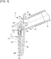
- the second embodiment of the present invention has the following configuration, workings, and effects shown in FIG. 10 in addition to those configurations, workings, and effects that have been described as applicable to the second embodiment of the present invention among the configurations, workings, and effects according to the first embodiment of the present invention.
- a cross-sectional area-reduced section 28a with a cross-sectional area decreasing gradually in the supercharged air flow direction, a throat 28b with a minimum cross-sectional area, and a cross-sectional area-increased section 28c with a cross-sectional area increasing gradually in the supercharged air flow direction are provided in the outlet pipe 28 in this order in the supercharged air flow direction, continuously from the rounded corner at the inlet of the outlet pipe 28.
- the outlet pipe 28 is a Venturi pipe in the second embodiment.
- the open end of the water suck-out pipe 32 leading into the outlet pipe 28 is located at a central portion of the throat 28b.
- the water suck-out pipe 32 protrudes from inside the low temperature-side tank 26 into the outlet pipe 28, and the open end of the water suck-out pipe 32 leading into the outlet pipe 28 is located at a central portion of the cross-section of the outlet pipe 28 at the throat 28b.
- the outlet pipe 28 is a Venturi pipe, it is possible to reduce the pressure loss and produce a low pressure at the open end of the water suck-out pipe 32 leading into the outlet pipe 28.
- the open end of the water suck-out pipe 32 leading into the outlet pipe 28 is located at the throat 28b, so that the Venturi effect of the outlet pipe 28 is further enhanced and the effect of sucking out the condensate water through the water suck-out pipe 32 is enhanced, compared with when the roundness of the corner at the inlet of the outlet pipe 28 alone is used.
- the low pressure at the throat 28b is partially recovered in the cross-sectional area-increased section 28c, so that the pressure loss of the flow of supercharged air in the outlet pipe 28 is reduced compared with when the cross-sectional area-increased section 28c is not provided.
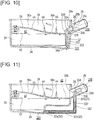
- the third embodiment of the present invention has the following configuration, workings, and effects shown in FIG. 11 in addition to those configurations, workings, and effects having been described as applicable to the third embodiment of the present invention among the configurations, workings, and effects according to the first embodiment of the present invention.
- the water suck-out pipe 32 couples the inside of the reservoir 30 to the inside of the outlet pipe 28 by extending from the low temperature-side tank 26 once to the outside of the low temperature-side tank 26.
- the water suck-out pipe 32 may be composed of a pipe 32a penetrating a wall of the reservoir 30, a pipe 32b penetrating a wall of the outlet pipe 28, and a hose 32c connecting the pipes 32a, 32b to each other outside the reservoir 30.
- the pipe 32b is formed so as to have the same structure as the lateral part 330 and the upper portion of the upright part 332 of the water suck-out pipe 32 described in the first embodiment, and the constriction 328 is formed in a portion of the condensate water discharge passage 32 located inside the lateral part 330.
- the fourth embodiment of the present invention has the following configuration, workings, and effects shown in FIG. 12 and FIG. 13 in addition to those configurations, workings, and effects having been described as applicable to the fourth embodiment of the present invention among the configurations, workings, and effects according to the first embodiment of the present invention.
- the core 24 is a cross-flow core through which the supercharged air flows in the left-right direction in FIG. 12 .
- the low temperature-side tank 26 extends in the upright direction.
- the low temperature-side tank 26 is extended to a position corresponding to a lower part of the core 24 or to a position further on the lower side than the position corresponding to the lower part of the core 24, and has the reservoir 30 at a position further on the lower side than the position corresponding to the lower part of the core 24.
- the outlet pipe 28 is provided in a region of the low temperature-side tank 26 other than the region where the reservoir 30 is provided, i.e., provided in an intermediate part or an upper end part of the low temperature-side tank 26 in the upright direction.
- the outlet pipe 28 extends toward the deep side in a direction orthogonal to the sheet of FIG. 12 , and extends in a direction orthogonal to the left-right direction in FIG. 12 .
- the water suck-out pipe 32 extends from the bottom of the reservoir 30 to a position at which the water suck-out pipe 32 opens inside the outlet pipe 28.
- the water suck-out pipe 32 may be located inside the low temperature-side tank 26 and the outlet pipe 28, or, although this is not shown, the water suck-out pipe 32 may extend from a side wall of the low temperature-side tank 26 once to the outside of the low temperature-side tank 26, penetrate a wall of the outlet pipe 28, and open inside the outlet pipe 28.
- the cross-flow intercooler 20 can also suck out the condensate water 12 while inhibiting the condensate water 12 from being sucked out at once.
- the partition plate 36 and the baffle plate 44 may be omitted.
- the partition plate 36 and the baffle plate 44 may be provided.
- the configurations, workings, and effects of the partition plate 36 and the baffle plate 44 having been described in the first embodiment as applicable to the fourth embodiment can be applied to the configurations, workings, and effects of the partition plate 36 and the baffle plate 44 in this case.
- the fifth embodiment of the present invention has the following configuration, workings, and effects shown in FIG. 14 in addition to those configurations, workings, and effects having been described as applicable to the fifth embodiment of the present invention among the configurations, workings, and effects according to the first embodiment of the present invention.
- the cross-sectional area-reduced section 28a with the cross-sectional area decreasing gradually in the supercharged air flow direction, the throat 28b with the minimum cross-sectional area, and the cross-sectional area-increased section 28c with the cross-sectional area increasing gradually in the supercharged air flow direction are provided in the outlet pipe 28 in this order in the supercharged air flow direction, continuously from the rounded corner at the inlet of the outlet pipe 28.
- the outlet pipe 28 is a Venturi pipe in the fifth embodiment.
- a hole 28d that extends in a direction orthogonal to the central axial line of the outlet pipe 28 is provided in a wall surface of the throat 28b.
- the water suck-out pipe 32 couples the inside of the reservoir 30 to the inside of the outlet pipe 28 by extending from inside the low temperature-side tank 26 once to the outside of the low temperature-side tank 26.
- the water suck-out pipe 32 may be composed of the pipe 32a penetrating the wall of the reservoir 30, the pipe 32b connected to the hole 28d, opened in the wall surface of the throat 28b of the outlet pipe 28, and fixed to the wall of the outlet pipe 28, and the hose 32c connecting the pipes 32a, 32b to each other outside the reservoir 30.
- the water suck-out pipe 32 does not enter the outlet pipe 28, but is connected to the hole 28d and opens to the inside of the outlet pipe 28 at the surface of the throat 28b.
- the constriction 328 is formed in the condensate water discharge passage 322 formed inside the pipe 32b.
- the water suck-out pipe 32 Since the water suck-out pipe 32 opens in the throat 28b of the outlet pipe 28 that is a Venturi pipe, the water suck-out pipe 32 uses the low pressure created at the throat 28b to suck out the condensate water 12 from inside the reservoir 30. Since the water suck-out pipe 32 does not protrude into the outlet pipe 28, the flow of supercharged air does not undergo a pressure loss that occurs as the supercharged air hits a protrusion of the water suck-out pipe 32.
- the hose 32c of the water suck-out pipe 32 is located outside the low temperature-side tank 26, even when the water suck-out pipe 32 does not reach the lowermost end of the low temperature-side tank 26 due to the depth, the complicated shape, etc. of the low temperature-side tank 26, the inside of the reservoir 30 and the inside of the outlet pipe 28 can be easily coupled through the hose 32c.
- the external size of the intercooler device 10 is increased compared with when the water suck-out pipe 32 is located inside the low temperature-side tank 26, but the flexibility of routing of the water suck-out pipe 32 is higher.
Landscapes
- Engineering & Computer Science (AREA)
- Mechanical Engineering (AREA)
- General Engineering & Computer Science (AREA)
- Chemical & Material Sciences (AREA)
- Combustion & Propulsion (AREA)
- Physics & Mathematics (AREA)
- Thermal Sciences (AREA)
- Health & Medical Sciences (AREA)
- Public Health (AREA)
- Water Supply & Treatment (AREA)
- Supercharger (AREA)
Description
- The present invention relates to an intercooler device of a supercharged internal combustion engine, and more particularly to a structure for discharging condensate water from an intercooler.
- As a conventional intercooler device of a supercharged internal combustion engine, Japanese Patent Application Publication No.
2012-117455 - Japanese Patent Application Publication No.
2012-102667 - However, since the collection part is not defined as a chamber separate from an intake gas flow in the conventional intercooler device of a supercharged internal combustion engine, the condensate water collected in the collection part may be carried away at once in a large amount due to the flow velocity of the intake gas flowing through the intercooler, causing malfunction (failure) of the internal combustion engine. In particular, water having frozen in a core part of the intercooler during cold-engine driving may melt and be collected inside the intercooler during stop of the internal combustion engine, and then this water may be carried away by an intake gas flow and suctioned into the internal combustion engine during engine start, causing malfunction of the internal combustion engine, such as fluid compression, rough idle, and abnormal noise. Moreover, a drain requires regular maintenance work.
- Documents
US 8 783 233 B2 andFR 2 957 980 A1 FR 2 908 505 A1 - A possible countermeasure is a structure in which a reservoir that temporarily collects condensate water generated in the intercooler is provided in a lower part of the low temperature-side tank of the intercooler, and in which a water suck-out pipe that extends from the bottom of the reservoir to a position at which the water suck-out pipe opens inside an outlet pipe of the intercooler is provided. In this structure, the condensate water collected in the reservoir is sucked out through the water suck-out pipe into the outlet pipe and discharged into the outlet pipe by means of a differential pressure between the pressure inside the reservoir and the pressure at the outlet of the water suck-out pipe inside the outlet pipe. The outer diameter of the water suck-out pipe is constant throughout the water suck-out pipe in its lengthwise direction.
- However, in the above countermeasure structure, if the outer diameter of the outlet of the water suck-out pipe is set so that an appropriate amount of condensate water is sucked out while the internal combustion engine is idling and the amount of air is small, an excessively large amount of condensate water is sucked out while a throttle valve is fully open and the amount of air is large, which may result in malfunction of the internal combustion engine. Conversely, if the outer diameter of the outlet of the water suck-out pipe is set so that an appropriate amount of condensate water is sucked out while the throttle valve is fully open, an excessively small amount of condensate water is sucked out during idling, which may result in an overflow of the condensate water inside the low temperature-side tank. Thus, there is room for improvement to discharge an appropriate amount of condensate water during idling as well as while the throttle valve is fully open.
- An object of the present invention is to provide an intercooler device of a supercharged internal combustion engine that is configured to suck out condensate water from inside a reservoir through a water suck-out pipe into an outlet pipe, and is capable of discharging an appropriate amount of condensate water during idling as well as while a throttle valve is fully open.
- An intercooler device of a supercharged internal combustion engine of the present invention to achieve the above object can have the following first to sixteenth aspects (aspects may read as configurations). The reference signs indicated in parentheses correspond to the reference signs appearing in the drawings.
- The present invention includes a first embodiment to a fifth embodiment to be described later. The relations between the following first to sixteenth aspects and the first embodiment to the fifth embodiment to be described later are as follows:
The first to fifth aspects are applicable to any one of the first embodiment to the fifth embodiment of the present invention. - The sixth to eleventh aspects are applicable to any one of the first embodiment to the fourth embodiment of the present invention.
- The twelfth aspect is applied to the first embodiment of the present invention. The thirteenth aspect is applied to the second embodiment of the present invention. The fourteenth aspect is applied to the third embodiment of the present invention. The fifteenth aspect is applied to the fourth embodiment of the present invention. The sixteenth aspect is applied to the fifth embodiment of the present invention.
- In the first aspect of the present invention, an intercooler device (10) of a supercharged internal combustion engine includes a low temperature-side tank (26) and an outlet pipe (28) extending from the low temperature-side tank (26). A reservoir (30) that temporarily collects condensate water is provided in a lower part of the low temperature-side tank (26). A water suck-out pipe (32) that extends from a bottom of the reservoir (30) to a position at which the water suck-out pipe (32) opens inside the outlet pipe (28) is provided. The intercooler device is configured so that an appropriate amount of condensate water (12) is sucked out from inside the reservoir (30) through the water suck-out pipe (32) while the internal combustion engine is idling.
- A constriction (328) that inhibits an excessive amount of condensate water from being sucked out through the water suck-out pipe (32) while a throttle valve of the internal combustion engine is fully open is defined in a condensate water discharge passage (322) formed inside the water suck-out pipe (32).
- The second aspect of the present invention is the intercooler device according to the first aspect, wherein an opening (326) of the water suck-out pipe (32) leading into the outlet pipe (28) is located upstream of the throttle valve in a supercharged air flow direction.
- The third aspect of the present invention is the intercooler device according to the first aspect, wherein the pressure difference between both ends of the water suck-out pipe (32) is set to 20 to 100 mm in head while the internal combustion engine is idling. The diameter of the constriction (328) is set to 1 to 3 mm.
- The fourth aspect of the present invention is the intercooler device according to the first aspect, wherein the constriction (328) is formed only in a part of the entire condensate water discharge passage (322) in its lengthwise direction.
- The fifth aspect of the present invention is the intercooler device according to the first aspect, wherein the diameter of the condensate water discharge passage (322) on both sides of the constriction (328) in a discharged condensate water flow direction is larger than the diameter of the constriction (328).
- The sixth aspect of the present invention is the intercooler device according to the first aspect, wherein the water suck-out pipe (32) includes an upright part (332) that has a portion opening at a bottom of the reservoir (30) and extending in an upright direction, and a lateral part (330) that is connected to an upper end of the upright part (332), extends in a lateral direction, and opens inside the outlet pipe (28). The outer diameter of the lateral part (330) of the water suck-out pipe (32) is larger than the outer diameter of the upright part (332) thereof, and is set to such a diameter that a pressure for sucking out an appropriate amount of condensate water (12) while the internal combustion engine is idling is created in a supercharged air passage part defined between an outer surface of the lateral part (330) and an inner surface of the outlet pipe (28).
- The seventh aspect of the present invention is the intercooler device according to the sixth aspect, wherein a central axial line of the lateral part (330) of the water suck-out pipe (32) is placed coaxially with a central axial line of the outlet pipe (28).
- The eighth aspect of the present invention is the intercooler device according to the sixth aspect, wherein the external form of at least one of an upper portion of the upright part (332) and the lateral part (330) of the water suck-out pipe (32) is shaped so as to reduce pressure loss of a flow of supercharged air flowing from the low temperature-side tank (26) into the outlet pipe (28).
- The ninth aspect of the present invention is the intercooler device according to the first aspect, wherein the diameter of the condensate water discharge passage (322) formed inside the water suck-out pipe (32) decreases gradually from a leading end of the water suck-out pipe (32) toward the constriction (328).
- The tenth aspect of the present invention is the intercooler device according to the sixth aspect, wherein the outer surface of the lateral part (330) of the water suck-out pipe (32) is provided with an outer diameter-reduced section (342) with an outer diameter decreasing gradually from a maximum outer diameter section (340) of the lateral part (330) toward a leading end.
- The eleventh aspect of the present invention is the intercooler device according to the sixth aspect, wherein a thinned section (344) for preventing sinks during molding of the water suck-out pipe (32) is provided around the constriction (328) in the lateral part (330) of the water suck-out pipe (32).
- The twelfth aspect of the present invention is the intercooler device according to the first aspect, wherein the low temperature-side tank (26) is provided with a partition plate (36) that partitions the inside of the low temperature-side tank (26) into upper and lower parts, and the water suck-out pipe (32) extends from inside the reservoir (30) to an upper chamber (38) by penetrating the partition plate (36), bends in the upper chamber (38), enters inside the outlet pipe (28) from inside the upper chamber (38), and opens inside the outlet pipe (28).
- The thirteenth aspect of the present invention is the intercooler device according to the first aspect, wherein a cross-sectional area-reduced section (28a) with a cross-sectional area decreasing gradually in an intake gas flow direction, a throat (28b) with a minimum cross-sectional area, and a cross-sectional area-increased section (28c) with a cross-sectional area increasing gradually in the intake gas flow direction are provided in the outlet pipe (28) in this order in the intake gas flow direction. An open end of the water suck-out pipe (32) leading into the outlet pipe (28) is located in a region inside the outlet pipe (28) corresponding to the throat (28b).
- The fourteenth aspect of the present invention is the intercooler device according to the first aspect, wherein the water suck-out pipe (32) couples the inside of the reservoir (30) to the inside of the outlet pipe (28) by extending once to the outside of the low temperature-side tank (26).
- The fifteenth aspect of the present invention is the intercooler device according to the first aspect, wherein an intercooler (20) includes a down-flow core (24) through which an intake gas flows downward or a cross-flow core (24) through which an intake gas flows in a crosswise direction. The outlet pipe (28) is provided in an upper end part or an intermediate part of the low temperature-side tank (26) in an upright direction. An area inside the low temperature-side tank (26) located further on the lower side than the outlet pipe (28) constitutes the reservoir (30), and the water suck-out pipe (32) extends from a bottom of the reservoir (30) to a position at which the water suck-out pipe (32) opens inside the outlet pipe (28).
- The sixteenth aspect of the present invention is the intercooler device according to the first aspect, wherein the water suck-out pipe (32) couples the inside of the reservoir (30) to the inside of the outlet pipe (28) by extending once to the outside of the low temperature-side tank (26). A cross-sectional area-reduced section (28a) with a cross-sectional area decreasing gradually in an intake gas flow direction, a throat (28b) with a minimum cross-sectional area, and a cross-sectional area-increased section (28c) with a cross-sectional area increasing gradually in the intake gas flow direction are provided in the outlet pipe (28) in this order in the intake gas flow direction. An open end of the water suck-out pipe (32) leading into the outlet pipe (28) is located at a wall surface of the throat (28b).
- According to any one of the first aspect to the fifth aspect of the present invention, the intercooler device is configured so that an appropriate amount of condensate water is sucked out from inside the reservoir through the water suck-out pipe while the internal combustion engine is idling and the amount of air is small. Moreover, the constriction is defined in the condensate water discharge passage of the water suck-out pipe, which inhibits an excessive amount of condensate water from being sucked out through the water suck-out pipe while the throttle valve of the internal combustion engine is fully open and the amount of air is large. As a result, an appropriate amount of condensate water can be discharged during idling as well as while the throttle valve is fully open.
- According to the sixth aspect of the present invention, increasing the outer diameter of the lateral part of the water suck-out pipe can create a pressure between the lateral part and the outlet pipe for sucking out an appropriate amount of condensate water while the internal combustion engine is idling, and thus can secure the efficiency of discharging condensate water during idling when the amount of air is small.
- According to the seventh aspect of the present invention, the central axial line of the lateral part of the water suck-out pipe is placed coaxially with the central axial line of the outlet pipe, and thus an increase in pressure loss of the supercharged air when the amount of air is large can be suppressed.
- According to the eighth aspect of the present invention, the external form of at least one of the upper portion of the upright part and the lateral part of the water suck-out pipe is shaped so as to reduce the pressure loss of the flow of supercharged air flowing from the low temperature-side tank into the outlet pipe. Thus, an increase in pressure loss of the supercharged air when the amount of air is large can be suppressed.
- According to the ninth aspect of the present invention, the diameter of the condensate water discharge passage formed inside the water suck-out pipe decreases gradually from the leading end of the water suck-out pipe toward the constriction. Thus, the condensate water undergoes a smaller pressure loss at the outlet of the constriction when the condensate water flows through the condensate water discharge passage, so that the pressure inside the water suck-out pipe is almost entirely conducted to the outlet of the constriction. As a result, a decrease in sucking out pressure is suppressed.
- According to the tenth aspect of the present invention, the outer surface of the lateral part of the water suck-out pipe is provided with the outer diameter-reduced section with the outer diameter decreasing gradually from the maximum outer diameter section of the lateral part toward the leading end. The flow of supercharged air undergoes a comparatively large pressure loss in a region corresponding to the inlet of the outlet pipe and the leading end of the water suck-out pipe where the flow passage sectional area changes rapidly. Thus, there is a smaller change in flow passage sectional area if the sectional area changes from the outer diameter-reduced section to the total sectional area of the outlet pipe than if the sectional area changes from the maximum outer diameter section to the total sectional area of the outlet pipe, and accordingly the pressure loss of the flow of supercharged air is smaller, so that a decrease in output of the internal combustion engine can be suppressed.
- According to the eleventh aspect of the present invention, the thinned section is provided around the constriction in the lateral part of the water suck-out pipe. Thus, sinks occurring around the constriction during molding of the water suck-out pipe are prevented, so that the constriction is formed with an accurate diameter and water is accurately sucked out.
- According to the twelfth aspect of the present invention, the water suck-out pipe extends from inside the reservoir to the upper chamber, bends in the upper chamber, enters inside the outlet pipe from inside the upper chamber, and opens inside the outlet pipe. Thus, it is possible to create a low pressure part for sucking out the condensate water around the outlet of the water suck-out pipe by means of the constriction of the flow of supercharged air when flowing from the low temperature-side tank into the outlet pipe.
- According to the thirteenth aspect of the present invention, the open end of the water suck-out pipe leading into the outlet pipe is provided in the throat. Thus, the Venturi effect of the outlet pipe is enhanced, and the effect of sucking out the condensate water through the water suck-out pipe is enhanced.
- According to the fourteenth aspect of the present invention, the water suck-out pipe couples the inside of the reservoir to the inside of the outlet pipe by extending once to the outside of the low temperature-side tank. Thus, the external size is increased, but the flexibility of routing of the water suck-out pipe is higher.
- According to the fifteenth aspect of the present invention, a cross-flow intercooler can also suck out condensate water while inhibiting the condensate water from being sucked out at once in a large amount.
- According to the sixteenth aspect of the present invention, the open end of the water suck-out pipe leading into the outlet pipe is located at the wall surface of the throat. Thus, the condensate water can be sucked out through the water suck-out pipe into the outlet pipe by the Venturi effect of the outlet pipe.
-
- [
FIG. 1] FIG. 1 is an overall front view of an intercooler device of a supercharged internal combustion engine (hereinafter also referred to simply as an "intercooler device") according to a first embodiment of the present invention. - [
FIG. 2] FIG. 2 is a sectional view of a low temperature-side tank and its vicinity in the intercooler device ofFIG. 1 as seen from the front side. - [
FIG. 3] FIG. 3 is a plan view of the low temperature-side tank and its vicinity in the intercooler device ofFIG. 1 . - [
FIG. 4] FIG. 4 is an enlarged sectional view of a water suck-out pipe and an outlet pipe and their vicinity in the intercooler device ofFIG. 1 . - [
FIG. 5] FIG. 5 is a sectional view of the water suck-out pipe and the outlet pipe ofFIG. 4 and their vicinity as seen along the line 5-5. - [
FIG. 6] FIG. 6 is a sectional view, applicable to any one of the first embodiment to a fourth embodiment of the present invention, of the water suck-out pipe and the outlet pipe and their vicinity in the intercooler device according to the first embodiment. - [
FIG. 7] FIG. 7 is a sectional view, applicable to any one of the first embodiment to the fourth embodiment of the present invention, of the water suck-out pipe and the outlet pipe and their vicinity in the intercooler device according to the first embodiment. - [
FIG. 8] FIG. 8 is a sectional view, applicable to any one of the first embodiment to the fourth embodiment of the present invention, of the water suck-out pipe and the outlet pipe and their vicinity in the intercooler device according to the first embodiment. - [
FIG. 9] FIG. 9 is a sectional view of the water suck-out pipe ofFIG. 8 as seen along the line 9-9. - [
FIG. 10] FIG. 10 is a sectional view, corresponding toFIG. 2 , of a low temperature-side tank and its vicinity in an intercooler device according to the second embodiment of the present invention as seen from the front side. - [
FIG. 11] FIG. 11 is a sectional view, corresponding toFIG. 2 , of a low temperature-side tank and its vicinity in an intercooler device according to the third embodiment of the present invention as seen from the front side. - [
FIG. 12] FIG. 12 is an overall front view of an intercooler device according to the fourth embodiment of the present invention. - [
FIG. 13] FIG. 13 is a side view of a low temperature-side tank and its vicinity in the intercooler device ofFIG. 12 . - [
FIG. 14 ] is a sectional view, corresponding toFIG. 2 , of a low temperature-side tank and its vicinity in an intercooler device according to a fifth embodiment of the present invention as seen from the front side. - An
intercooler device 10 of a supercharged internal combustion engine of the present invention will be described with reference to the drawings.FIG. 1 to FIG. 9 show a first embodiment of the present invention;FIG. 10 shows a second embodiment of the present invention;FIG. 11 shows a third embodiment of the present invention;FIG. 12 and FIG. 13 show a fourth embodiment of the present invention; andFIG. 14 shows a fifth embodiment of the present invention. Structural parts that are the same or correspond to each other in all the embodiments of the present invention will be denoted by the same reference signs in all the embodiments of the present invention. - First, the configuration of the first embodiment of the present invention will be described with reference to
FIG. 1 to FIG. 9 . - As shown in
FIG. 1 , theintercooler device 10 of a supercharged internal combustion engine of the present invention includes anintercooler 20 in a supercharged air passage of the internal combustion engine. In the drawings, the arrow F indicates a rough flow direction of supercharged air (also referred to as an "intake gas"). The supercharged internal combustion engine may be a spark-ignition internal combustion engine or a diesel internal combustion engine. The supercharger may be a turbocharger or a mechanical supercharger other than a turbocharger. Theintercooler 20 is a heat exchanger installed in the supercharged air passage, and serves to increase the charging efficiency of the internal combustion engine by cooling the supercharged air that has been compressed by the supercharger and has an elevated temperature. A throttle valve is provided downstream of theintercooler 20, between theintercooler 20 and the internal combustion engine, and a surge tank and an intake manifold are provided between the throttle valve and the internal combustion engine. - The
intercooler 20 includes a high temperature-side tank 22 into which the supercharged air flows, an intercooler core (hereinafter simply referred to as a "core") 24 where heat exchange takes place, and a low temperature-side tank 26 from which the supercharged air flows out. Aninlet pipe 14 that is an inlet into theintercooler 20 for the supercharged air is connected to the high temperature-side tank 22, and anoutlet pipe 28 that is an outlet from theintercooler 20 for the supercharged air is connected to the low temperature-side tank 26. Theinlet pipe 14, the high temperature-side tank 22, thecore 24, the low temperature-side tank 26, and theoutlet pipe 28 are provided in this order in a supercharged air flow direction. Theinlet pipe 14 and theoutlet pipe 28 may be formed integrally with theintercooler 20, or may be formed separately from theintercooler 20 and coupled to theintercooler 20. The drawings show the case where these pipes are formed integrally. The high temperature-side tank 22 is supported on a vehicle body through abracket 16, and the low temperature-side tank 26 is supported on the vehicle body throughribs 18 - The core 24 may be a down-flow core through which the supercharged air flows downward as shown in
FIG. 1 to FIG. 3 , or may be a cross-flow core through which the supercharged air flows in a crosswise direction as shown inFIG. 12 and FIG. 13 to be described later. In the case of the down-flow core, the high temperature-side tank 22 is provided on the upper side of thecore 24 and the low temperature-side tank 26 is provided on the lower side of thecore 24. In the case of the cross-flow core, the high temperature-side tank 22 and the low temperature-side tank 26 are provided on left and right sides of thecore 24. As conventionally known structures are adopted as the structures of the high temperature-side tank 22 and thecore 24, description of the details thereof will be omitted. Condensate water generated in thecore 24 is collected in the low temperature-side tank 26. - It is desirable that the
outlet pipe 28 extend obliquely upward from a side wall of the low temperature-side tank 26 toward the throttle valve. In this case, any condensate water overflowing from inside the low temperature-side tank 26 into theoutlet pipe 28 returns by gravity to the low temperature-side tank 26. A hose 52 (FIG. 4 ) or a pipe constituting a part of an intake passage of the internal combustion engine is connected to theoutlet pipe 28. - As shown in
FIG. 1 andFIG. 2 , areservoir 30 that temporarily collectscondensate water 12 is provided in a lower part of the low temperature-side tank 26. The internal space of the low temperature-side tank 26 may be divided into upper and lower parts by apartition plate 36. In the case where thepartition plate 36 is provided, anupper chamber 38 through which the supercharged air flows is formed on the upper side of thepartition plate 36, and thereservoir 30 is formed on the lower side of thepartition plate 36. Theoutlet pipe 28 opens to theupper chamber 38. In the case where thepartition plate 36 is provided, thepartition plate 36 is provided with awater fall opening 40 through which the condensate water on thepartition plate 36 is let fall to thereservoir 30. Since thereservoir 30 is provided and the condensate water is temporarily collected in thereservoir 30, the condensate water having entered the low temperature-side tank 26 does not flow out at once, so that malfunction of the internal combustion engine due to the condensate water is suppressed. - The low temperature-
side tank 26 is provided with a water suck-outpipe 32 that extends from a bottom of thereservoir 30 to a position at which the water suck-outpipe 32 opens inside theoutlet pipe 28. The condensate water 12 (FIG. 2 ) collected inside thereservoir 30 is sucked out in an appropriate amount from the bottom of thereservoir 30 through the water suck-outpipe 32 into theoutlet pipe 28. The position at which the water suck-outpipe 32 opens inside theoutlet pipe 28 is located upstream of the throttle valve in the supercharged air flow direction, and thus sucking out of thecondensate water 12 through the water suck-outpipe 32 is not sucking out by means of an intake negative pressure downstream of the throttle valve. - The
outlet pipe 28 is located downstream of the low temperature-side tank 26 in the supercharged air flow direction. The supercharged air passage sectional area inside theoutlet pipe 28 is smaller than the supercharged air passage sectional area inside the low temperature-side tank 26, and the flow velocity of the supercharged air inside theoutlet pipe 28 is higher than the flow velocity of the supercharged air inside the low temperature-side tank 26. As the supercharged air from inside the low temperature-side tank 26 increases its flow velocity inside theoutlet pipe 28, part of the static pressure inside the low temperature-side tank 26 is converted into a dynamic pressure inside theoutlet pipe 28, resulting in the static pressure inside theoutlet pipe 28 falling below the static pressure inside the low temperature-side tank 26. Due to the Venturi effect caused by a decrease in static pressure attributable to the difference in flow velocity, and to a pressure loss of the supercharged air, especially a pressure loss at the inlet of theoutlet pipe 28, the static pressure of the supercharged air inside theoutlet pipe 28 is lower than the static pressure of the supercharged air inside the low temperature-side tank 26. This pressure difference causes the condensate water 12 (FIG. 2 ) collected inside thereservoir 30 to be sucked out from the bottom of thereservoir 30 through the water suck-outpipe 32 into theoutlet pipe 28. - As shown in
FIG. 1 to FIG. 13 , the opening of the water suck-outpipe 32 toward theoutlet pipe 28 may be located inside theoutlet pipe 28 in a region away from an inner wall surface of theoutlet pipe 28, or may be located at the inner wall surface of theoutlet pipe 28 as shown inFIG. 14 to be described later. To avoid being subjected to the dynamic pressure of the flow of supercharged air, the water suck-outpipe 32 opens further toward the downstream side in the supercharged air flow direction than a direction orthogonal to the supercharged air flow direction, or opens in a direction orthogonal to the supercharged air flow direction. The water suck-outpipe 32 protrudes from inside the low temperature-side tank 26 into the outlet pipe 28 (FIG. 1 to FIG. 10 orFIG. 12 and FIG. 13 ), or protrudes into theoutlet pipe 28 in a region of the outlet pipe 28 (FIG. 11 ), or terminates at the inner wall surface of the outlet pipe 28 (FIG. 14 ). - As shown in
FIG. 2 , abottom wall 34 of thereservoir 30 descends toward an end of the water suck-outpipe 32 on the side of thereservoir 30, and a part of thebottom wall 34 of thereservoir 30 in the vicinity of the end of the water suck-outpipe 32 on the side of thereservoir 30 forms alowermost part 34a of thebottom wall 34 of thereservoir 30. Thus, thecondensate water 12 inside thereservoir 30 is gathered toward a lower end of the water suck-outpipe 32. In the case where the end of the water suck-outpipe 32 on the side of thereservoir 30 extends in an upright direction, it is desirable that the end on the side of thereservoir 30 be cut obliquely relative to thebottom wall 34 of thereservoir 30 so that the end is not closed by coming in close contact with thebottom wall 34 of thereservoir 30. - As shown in
FIG. 1 andFIG. 2 , in the case where the water suck-outpipe 32 is disposed inside the low temperature-side tank 26, the water suck-outpipe 32 may extend from thereservoir 30 to theupper chamber 38 by penetrating thepartition plate 36. A region of thepartition plate 36 penetrated by the water suck-outpipe 32 may be a region where thewater fall opening 40 is provided, or may be a region other than the region where thewater fall opening 40 is provided. If the region of thepartition plate 36 penetrated by the water suck-outpipe 32 appears in the drawings but thewater fall opening 40 does not, this means that the region of thepartition plate 36 penetrated by the water suck-outpipe 32 and the position of thewater fall opening 40 do not coincide with each other, and that thewater fall opening 40 does not appear in the drawings because the region of thepartition plate 36 penetrated by the water suck-outpipe 32 is shown. - In the case where the
partition plate 36 is provided, thepartition plate 36 has an upstream-side part 36a and a downstream-side part 36b in the supercharged air flow direction inside theupper chamber 38 as shown inFIG. 2 . Thepartition plate 36 is formed in a shape descending from the upstream-side part 36a toward the downstream-side part 36b, and guides the flow of supercharged air F into theoutlet pipe 28. Thewater fall opening 40 is provided in the downstream-side part 36b of thepartition plate 36. It is desirable that a part of thepartition plate 36 in the vicinity of thewater fall opening 40 be inclined so as to descend toward thewater fall opening 40. - As shown in
FIG. 2 , the upstream-side part 36a of thepartition plate 36 forms aspace 42, on the lower surface side of the upstream-side part 36a, that serves to absorb an expansion of the volume of thecondensate water 12 upon freezing when thecondensate water 12 collected inreservoir 30 freezes while closing thewater fall opening 40. Thespace 42 is a space defined between the lower surface of the upstream-side part 36a of thepartition plate 36 and an upper surface of thecondensate water 12 in a state where thecondensate water 12 closes thewater fall opening 40. - In the case where the
partition plate 36 is provided, it is desirable thatbaffle plates 44 be provided on the upper surface of thepartition plate 36 as shown inFIG. 1 to FIG. 3 . Thebaffle plates 44 are disposed so as to block the flow of thecondensate water 12 from the low temperature-side tank 26 to theoutlet pipe 28 when thecondensate water 12 overflows from thereservoir 30 onto thepartition plate 36. However, thebaffle plates 44 are each provided with one ormore openings 46 through which the water on thepartition plate 36 can pass so as not to completely stem the flow of thecondensate water 12 from the low temperature-side tank 26 to theoutlet pipe 28. Theopening 46 may be a slit that is opened along theentire baffle plate 44 in its height direction, or may be a hole that is opened in a part of thebaffle plate 44 in its height direction. Thebaffle plate 44 extends across opposite side surfaces of the low temperature-side tank 26 except for the region where theopening 46 is provided. The number, interval, height (the height from thepartition plate 36 to an upper end of the baffle plate 44), and arrangement of thebaffle plates 44 are set so that, when the condensate water overflows onto thepartition plate 36 and a fluid collection is formed up to the position of the upper end of thebaffle plate 44, all of the amount of fluid collected between thebaffle plates 44, the amount of fluid collected downstream of the mostdownstream baffle plate 44, and the amount of fluid collected upstream of the mostupstream baffle plate 44 do not exceed such an amount as leads to malfunction of the internal combustion engine even if the condensate water is carried away by the flow of supercharged air at once into the internal combustion engine. - As shown in
FIG. 1 andFIG. 2 , a cross-sectional area of theupper chamber 38 larger than the cross-sectional area of theoutlet pipe 28 is secured on the upper side of thebaffle plate 44 that is the lower side of thecore 24. The cross-sectional area is the product of a distance S between the upper end of thebaffle plate 44 and the lower end of thecore 24 and the width of the low temperature-side tank 26. In the example shown in the drawings, the upper ends of the plurality ofbaffle plates 44 are located nearly at the same level, and the cross-sectional area larger than the cross-sectional area of theoutlet pipe 28 is secured on the upper side of the plurality ofbaffle plates 44. Thus, the pressure loss that the supercharged air undergoes when flowing through theupper chamber 38 is reduced to be equal to or smaller than the pressure loss when flowing through theoutlet pipe 28. - As shown in
FIG. 3 , to avoid all theopenings 46 provided in thebaffle plates 44 being located on the same straight line (e.g., a straight line passing through theopening 46 provided in any one of thebaffle plates 44 and parallel to the opposite side surfaces of the low temperature-side tank 26 extending in a direction along the supercharged air flow direction), theopening 46 provided in at least onebaffle plate 44 is located off that straight line. - To set the differential pressure between both ends of the water suck-out
pipe 32 so that thecondensate water 12 temporarily collected inside thereservoir 30 is sucked out in an appropriate amount through the water suck-outpipe 32 into theoutlet pipe 28, the pressure difference when the amount of air inside the internal combustion engine is small, for example, during idling, serves as a reference. Specifically, the pressure difference between both ends of the water suck-outpipe 32 while the internal combustion engine is idling is desirably about 20 to 100 mm, and more desirably about 30 to 80 mm, in head so that the condensate water does not overflow inside the low temperature-side tank 26 while the internal combustion engine is idling. The height of thereservoir 30 and the distance in the upright direction between both ends of the water suck-outpipe 32 are determined accordingly. However, the head values are not limited to these values. - To produce an appropriate low condensate water sucking out pressure at the outlet pipe-side end of the water suck-out
pipe 32 while the internal combustion engine is idling, the outer diameter of the water suck-outpipe 32 at the outlet pipe-side end is larger than the outer diameter of the water suck-outpipe 32 at the other part than the outlet pipe-side end. Thus, the supercharged air passage sectional area defined between the inner diameter of theoutlet pipe 28 and the outer diameter of the water suck-outpipe 32 at the outlet pipe-side end is reduced at the outlet pipe-side end of the water suck-outpipe 32, so that the pressure at the outlet pipe-side end of the water suck-outpipe 32 is reduced. Alternatively, instead of the outer diameter of the water suck-outpipe 32 at the outlet pipe-side end being increased, or in addition to the outer diameter of the water suck-outpipe 32 at the outlet pipe-side end being increased, the inner diameter of theoutlet pipe 28 may be reduced as shown inFIG. 10 andFIG. 14 to thereby reduce the pressure at the outlet pipe-side end of the water suck-outpipe 32. - If it is ensured that an appropriate low condensate water sucking out pressure is produced at the outlet pipe-side end of the water suck-out
pipe 32 while the internal combustion engine is idling, the condensate water sucking out pressure of the water suck-outpipe 32 becomes too high while the throttle valve is fully open and the amount of air inside the internal combustion engine is large. Aconstriction 328 with the diameter reduced to a constant value (e.g., 1 to 3 mm, desirably 2 mm, but not limited to 3 mm, 2 mm, or 1 mm) is formed in the condensatewater discharge passage 322 formed inside the water suck-outpipe 32, only in a part of the condensatewater discharge passage 322 in its lengthwise direction so that, even when the amount of air inside the internal combustion engine is large, malfunction of the internal combustion engine is not caused as thecondensate water 12 temporarily collected inside thereservoir 30 is sucked out in a large amount at once into theoutlet pipe 28. In other words, theconstriction 328 that inhibits an excessive amount of condensate water from being sucked out through the water suck-outpipe 32 while the throttle valve of the internal combustion engine is fully open is defined in the condensatewater discharge passage 322 of the water suck-outpipe 32. - The diameter of the condensate
water discharge passage 322 increases at least on both sides of theconstriction 328, and changes in at least two stages over the entire condensatewater discharge passage 322 in its lengthwise direction. If the diameter of the condensatewater discharge passage 322 is reduced throughout the condensatewater discharge passage 322 in its lengthwise direction, the amount of condensate water sucked out during idling decreases, which may result in an overflow of the condensate water inside the low temperature-side tank 26 during idling. Therefore, theconstriction 328 is provided only in a part of the entire condensatewater discharge passage 322 in its lengthwise direction, i.e., only in a part thereof from a reservoir-side opening 324 to an outlet-side opening 326. - It is desirable that the water suck-out
pipe 32, the low temperature-side tank 26, thepartition plate 36, and thebaffle plate 44 be made of plastic or aluminum alloy, for example, in view of the light weight and moldability. In the example shown in the drawings, the water suck-outpipe 32 is made of plastic, and the low temperature-side tank 26, thepartition plate 36, and thebaffle plate 44 are made of aluminum alloy. - The foregoing configuration of the first embodiment is applicable to all the embodiments (first embodiment to fifth embodiment) of the present invention.
- The first embodiment of the present invention further has the following detailed structure.
- As shown in
FIG. 1 to FIG. 4 , the water suck-outpipe 32 includes anupright part 332 that has a portion having a lower end opening at the bottom of thereservoir 30 and extending in the upright direction, and alateral part 330 that has one end connected to an upper end of theupright part 332, extends in a lateral direction, and opens inside theoutlet pipe 28 at the other end. The upright direction in which theupright part 332 extends may be the vertical direction or may be inclined relative to the vertical direction. The lateral direction in which thelateral part 330 extends may be the horizontal direction or may be inclined relative to the horizontal direction. In the example shown in the drawings, thelateral part 330 extends obliquely upward in a direction away from the low temperature-side tank 26. - As shown in
FIG. 4 andFIG. 6 toFIG. 8 , the water suck-outpipe 32 may be formed as two divided parts, of which one is a head part composed of thelateral part 330 and an upper portion of theupright part 332 and the other is a leg part composed of an intermediate portion and a lower portion of theupright part 332, and then the two parts may be assembled with a lower end of the head part inserted into an upper end of the leg part. - The outer diameter of the
lateral part 330 of the water suck-outpipe 32 is larger than the outer diameter of theupright part 332. Thus, the outer diameter is set to such a diameter that a low pressure for sucking out an appropriate amount of condensate water while the internal combustion engine is idling is created in a supercharged air passage part defined between an outer surface of thelateral part 330 and the inner surface of theoutlet pipe 28. - As shown in
FIG. 4 , a central axial line of thelateral part 330 of the water suck-outpipe 32 is placed coaxially with a central axial line of theoutlet pipe 28. The central axial line of thelateral part 330 and the central axial line of theoutlet pipe 28 coincide with each other. Thus, the supercharged air passage sectional area inside theoutlet pipe 28 is uniform around the central axial line, so that the pressure loss of the supercharged air is smaller than when the central axial line of thelateral part 330 and the central axial line of theoutlet pipe 28 do not coincide with each other. - As shown in
FIG. 4 to FIG. 7 , the external form of at least one of the upper portion of theupright part 332 and thelateral part 330 of the water suck-outpipe 32 is shaped so as to reduce the pressure loss of the flow of supercharged air flowing from theupper chamber 38 of the low temperature-side tank 26 into theoutlet pipe 28. - Specifically, as shown in
FIG. 4 , a pressureloss reducing shape 334 that has a recessed external form defined by a curved or bent line is formed along the flow of supercharged air in a portion of the water suck-outpipe 32 transitioning from the upper portion of theupright part 332 to thelateral part 330, the portion that comes in contact with the flow of supercharged air flowing from theupper chamber 38 of the low temperature-side tank 26 into theoutlet pipe 28. The pressureloss reducing shape 334 reduces the pressure loss of the flow of supercharged air. - Moreover, as shown in
FIG. 5 , a pressureloss reducing shape 336 having an external form tapered in a direction opposite from the supercharged air flow direction is formed at a cross-section of the water suck-outpipe 32 orthogonal to the central axial line in the upper portion of theupright part 332, at the portion that comes in contact with the flow of supercharged air flowing from theupper chamber 38 of the low temperature-side tank 26 into theoutlet pipe 28. The pressureloss reducing shape 336 reduces the pressure loss of the flow of supercharged air. - In the first embodiment of the present invention, as shown in
FIG. 6 , the diameter of the condensatewater discharge passage 322 formed inside the water suck-outpipe 32 may decrease gradually in asection 338 extending from the leading end of the water suck-outpipe 32 on the side of theoutlet pipe 28 toward theconstriction 328. To look at this in the opposite direction, the diameter of the condensatewater discharge passage 322 may increase gradually from the side of theconstriction 328 toward the leading end of the water suck-outpipe 32 on the side of theoutlet pipe 28. Thus, the pressure loss that the condensate water undergoes when flowing through the condensatewater discharge passage 322 is reduced, so that the low pressure created at the leading end of the water suck-outpipe 32 on the side of theoutlet pipe 28 is almost entirely conducted to theconstriction 328, which allows favorable sucking out of the condensate water during idling. - As shown in
FIG. 7 , thelateral part 330 of the water suck-outpipe 32 may be provided with an outer diameter-reducedsection 342 with an outer diameter decreasing gradually from a maximumouter diameter section 340 of thelateral part 330 toward the leading end. Thus, the supercharged air passage sectional area inside theoutlet pipe 28, which reaches its minimum in the maximumouter diameter section 340 of thelateral part 330, increases at the leading end of thelateral part 330, so that the low pressure around the maximumouter diameter section 340 is gradually recovered before reaching the leading end of thelateral part 330. As a result, the pressure loss of the flow of supercharged air at the leading end of thelateral part 330 is reduced, and a decrease in output of the internal combustion engine is suppressed. - As shown in
FIG. 8 and FIG. 9 , a thinnedsection 344 for preventing sinks during molding of the water suck-outpipe 32 may be provided around theconstriction 328 in thelateral part 330 of the water suck-outpipe 32. The thinnedsection 344 may be provided along the entire circumference of theconstriction 328, or may be provided only in a part of the circumference of theconstriction 328. In the case where the thinnedsection 344 is provided only in a part of the circumference of theconstriction 328, it is desirable that the thinnedsection 344 be provided along about half the circumference of the water suck-outpipe 32, on the inner side of a section bent from theupright part 332 to thelateral part 330 where the wall tends to be thick. Providing the thinnedsection 344 can suppress shrinkage sinks around theconstriction 328 during molding of the water suck-outpipe 32, so that theconstriction 328 can be molded with an accurate inner diameter, and excessive sucking out of the condensate water while the throttle valve is fully open can be inhibited with high accuracy. - The foregoing detailed structure of the first embodiment of the present invention is applicable to the first embodiment to the fourth embodiment.
- The first embodiment of the present invention further has the following structure.
- As shown in
FIG. 1 andFIG. 2 , the water suck-outpipe 32 penetrates thepartition plate 36 that is provided inside the low temperature-side tank 26 and partitions the inside of the low temperature-side tank 26 into upper and lower parts. The water suck-outpipe 32 extends from inside thereservoir 30 to theupper chamber 38 by penetrating thepartition plate 36, bends in theupper chamber 38 toward theoutlet pipe 28, enters inside theoutlet pipe 28 from inside theupper chamber 38, and opens inside the outlet pipe. - To reduce the pressure loss of the flow of supercharged air, a corner formed by the inlet of the
outlet pipe 28 and the side wall of the low temperature-side tank 26 is rounded. Thus, the flow of supercharged air is smoothly constricted at the inlet of theoutlet pipe 28. Accordingly, the inlet of theoutlet pipe 28 works like a part with a reduced sectional area of a Venturi pipe, so that a low pressure like that in a throat of a Venturi pipe is created in a region inside theoutlet pipe 28 at a small distance from the inlet. It is desirable that the leading end of the water suck-outpipe 32 inside theoutlet pipe 28 be disposed in a region inside theoutlet pipe 28 at a small distance from the inlet, and that a low pressure created thereby inside theoutlet pipe 28 be used to suck out the condensate water. - Next, the workings and effects of the first embodiment of the present invention will be described.
- In the related art, condensate water that has frozen inside the
intercooler 20 during cold driving and then melts and is collected inside the low temperature-side tank 26 during stop of the internal combustion engine may be suctioned into the internal combustion engine at once in a large amount by an intake gas flow during start of the internal combustion engine, causing malfunction of the internal combustion engine, such as fluid compression and rough idle. This condensate water may include condensate water that has frozen inside theintercooler 20 and then melts and is collected inside the low temperature-side tank 26 during operation of the internal combustion engine, and that is suctioned at once in a large amount into the internal combustion engine. - By contrast, suctioning of a large amount of
condensate water 12 at once into the internal combustion engine is inhibited or prevented in the present invention, as thecondensate water 12 is temporarily discharged into thereservoir 30 from the space inside theupper chamber 38 through which the supercharged air flows. In particular, if thereservoir 30 is separated from theupper chamber 38 by thepartition plate 36, the condensate water inside thereservoir 30 is not carried away at once in a large amount into theoutlet pipe 28 by the flow of supercharged air flowing through theupper chamber 38. Moreover, thecondensate water 12 is let fall from theupper chamber 38, through which the supercharged air flows, through thewater fall opening 40 into thereservoir 30, so that thecondensate water 12 is inhibited from collecting in a large amount on thepartition plate 36. As a result, thecondensate water 12 on thepartition plate 36 is inhibited from being suctioned at once in a large amount into the internal combustion engine. As a result of these, malfunction of the internal combustion engine, such as fluid compression and rough idle, is suppressed or prevented. - Since the water suck-out
pipe 32 that extends from the bottom of thereservoir 30 to a position at which the water suck-outpipe 32 opens inside theoutlet pipe 28 is provided, thecondensate water 12 temporarily collected inside thereservoir 30 is sucked out in appropriate amounts through the water suck-outpipe 32 into theoutlet pipe 28 by the pressure difference between a region of the low temperature-side tank 26 and a region of theoutlet pipe 28 attributable to differences in flow velocity, pressure loss, etc. between the region of the low temperature-side tank 26 and the region of theoutlet pipe 28. A part or the whole of the condensate water discharged into theoutlet pipe 28 is evaporated in the internal combustion engine, and is discharged through an exhaust pipe to the outside. - Since the water suck-out
pipe 32 is located upstream of the throttle valve and an intake negative pressure downstream of the throttle valve is not used for sucking out the condensate water, even a vehicle with a small engine capacity is unlikely to fail to suck out condensate water due to a lack of negative pressure in a low-speed range. Moreover, since the intake negative pressure is not used, a vacuum pipe from theintercooler 20 to the intake manifold is not required, and work and space required for routing the vacuum pipe are not required, either. - The amount of condensate water sucked out from inside the
reservoir 30 through the water suck-outpipe 32 is set so as to be an appropriate amount while the internal combustion engine is idling and the amount of air is small. Thus, an appropriate amount of condensate water can be discharged during idling as well, and an overflow of the condensate water inside the low temperature-side tank 26 during idling is prevented. Moreover, theconstriction 328 is provided in the condensatewater discharge passage 322 of the water suck-outpipe 32, which inhibits an excessive amount of condensate water from being sucked out through the water suck-outpipe 32 while the throttle valve of the internal combustion engine is fully open and the amount of air is large. As a result, an appropriate amount of condensate water can be discharged during idling as well as while the throttle valve is fully open. The foregoing workings and effects are applicable to all the embodiments (first embodiment to fifth embodiment) of the present invention. - The first embodiment of the present invention further has the following workings and effects.
- In the example of
FIG. 2 andFIG. 4 , the outer diameter of thelateral part 330 of the water suck-outpipe 32 is increased, so that a low pressure for sucking out an appropriate amount of condensate water while the internal combustion engine is idling can be easily created between thelateral part 330 and theoutlet pipe 28. Thus, the efficiency of discharging condensate water during idling when the amount of air is small can be secured. - Since the central axial line of the
lateral part 330 of the water suck-outpipe 32 is placed coaxially with the central axial line of theoutlet pipe 28, an increase in pressure loss of the supercharged air flowing through theoutlet pipe 28 when the amount of air is large can be suppressed. - The external shapes of the pressure
loss reducing shapes upright part 332 and thelateral part 330 of the water suck-outpipe 32 are shaped so as to reduce the pressure loss of the flow of supercharged air flowing from the low temperature-side tank 26 into theoutlet pipe 28. Thus, an increase in pressure loss of the supercharged air flowing through theoutlet pipe 28 when the amount of air is large can be suppressed. - In the example of
FIG. 6 , the diameter of the condensatewater discharge passage 322 formed inside the water suck-outpipe 32 decreases gradually from the leading end of the water suck-outpipe 32 toward theconstriction 328. Thus, the condensate water undergoes a smaller pressure loss at the outlet of theconstriction 328 when the condensate water flows through the condensatewater discharge passage 322, so that the low pressure at the leading end of the water suck-outpipe 32 is almost entirely conducted to the outlet of theconstriction 328. As a result, a decrease in condensate water sucking out pressure of the water suck-outpipe 32 over the section from the leading end of the water suck-outpipe 32 to theconstriction 328 is suppressed, and the condensate water can be sucked out by a strong low pressure. - In the example of
FIG. 7 , the outer surface of thelateral part 330 of the water suck-outpipe 32 is provided with the outer diameter-reducedsection 342 with the outer diameter decreasing gradually from the maximumouter diameter section 340 of thelateral part 330 toward the leading end. In general, the flow of supercharged air undergoes a comparatively large pressure loss in a region corresponding to the inlet of theoutlet pipe 28 and the leading end of the water suck-outpipe 32 where the flow passage sectional area changes rapidly. Thus, there is a smaller change in flow passage sectional area at a region corresponding to the leading end of the water suck-outpipe 32 if the sectional area changes from the outer diameter-reducedsection 342 to the total sectional area of the outlet pipe than if the sectional area changes from the maximumouter diameter section 342 to the total sectional area of the outlet pipe, and accordingly the pressure loss of the flow of supercharged air is smaller, so that a decrease in output of the internal combustion engine can be suppressed. - In the example shown in
FIG. 8 and FIG. 9 , the thinnedsection 344 is provided around theconstriction 328 in thelateral part 330 of the water suck-outpipe 32. Thus, shrinkage sinks around theconstriction 328 is suppressed during molding of the water suck-outpipe 32. As a result, theconstriction 328 is formed with an accurate diameter, and an excessive sucking out of the condensate water while the throttle valve is fully open can be appropriately inhibited. - The foregoing workings and effects of the examples of
FIG. 2 ,FIG. 4 , andFIG. 6 toFIG. 9 are applicable to the first embodiment to the fourth embodiment of the present invention. - In the example of
FIG. 2 andFIG. 4 , the water suck-outpipe 32 extends from inside thereservoir 30 to theupper chamber 38, bends in theupper chamber 38, enters inside theoutlet pipe 28 from inside theupper chamber 38, and opens inside theoutlet pipe 28. Thus, a low pressure part for sucking out the condensate water can be created around the outlet of the water suck-outpipe 32 by means of the constriction of the flow of supercharged air at the inlet of theoutlet pipe 28 when the supercharged air flows from the low temperature-side tank 26 into theoutlet pipe 28. - In the example of
FIG. 2 andFIG. 4 , the water suck-outpipe 32 is disposed inside the low temperature-side tank 26 and theoutlet pipe 28, so that, even when the water suck-outpipe 32 is provided, the external size of the low temperature-side tank 26 and theoutlet pipe 28 is not increased compared with that of the related art in which the water suck-outpipe 32 is not provided. As a result, theintercooler device 10 is compact and offers excellent ease of installation in a vehicle. - The foregoing workings and the effects of the example of
FIG. 2 andFIG. 4 are applicable to the second embodiment and the fourth embodiment of the present invention. - The second embodiment of the present invention has the following configuration, workings, and effects shown in
FIG. 10 in addition to those configurations, workings, and effects that have been described as applicable to the second embodiment of the present invention among the configurations, workings, and effects according to the first embodiment of the present invention. - First, the configuration will be described. A cross-sectional area-reduced
section 28a with a cross-sectional area decreasing gradually in the supercharged air flow direction, athroat 28b with a minimum cross-sectional area, and a cross-sectional area-increasedsection 28c with a cross-sectional area increasing gradually in the supercharged air flow direction are provided in theoutlet pipe 28 in this order in the supercharged air flow direction, continuously from the rounded corner at the inlet of theoutlet pipe 28. Thus, theoutlet pipe 28 is a Venturi pipe in the second embodiment. The open end of the water suck-outpipe 32 leading into theoutlet pipe 28 is located at a central portion of thethroat 28b. - In the example of
FIG. 10 , the water suck-outpipe 32 protrudes from inside the low temperature-side tank 26 into theoutlet pipe 28, and the open end of the water suck-outpipe 32 leading into theoutlet pipe 28 is located at a central portion of the cross-section of theoutlet pipe 28 at thethroat 28b. - Next, the workings and effects will be described. Since the
outlet pipe 28 is a Venturi pipe, it is possible to reduce the pressure loss and produce a low pressure at the open end of the water suck-outpipe 32 leading into theoutlet pipe 28. Specifically, the open end of the water suck-outpipe 32 leading into theoutlet pipe 28 is located at thethroat 28b, so that the Venturi effect of theoutlet pipe 28 is further enhanced and the effect of sucking out the condensate water through the water suck-outpipe 32 is enhanced, compared with when the roundness of the corner at the inlet of theoutlet pipe 28 alone is used. Moreover, the low pressure at thethroat 28b is partially recovered in the cross-sectional area-increasedsection 28c, so that the pressure loss of the flow of supercharged air in theoutlet pipe 28 is reduced compared with when the cross-sectional area-increasedsection 28c is not provided. - The third embodiment of the present invention has the following configuration, workings, and effects shown in
FIG. 11 in addition to those configurations, workings, and effects having been described as applicable to the third embodiment of the present invention among the configurations, workings, and effects according to the first embodiment of the present invention. - First, the configuration will be described. The water suck-out
pipe 32 couples the inside of thereservoir 30 to the inside of theoutlet pipe 28 by extending from the low temperature-side tank 26 once to the outside of the low temperature-side tank 26. For example, the water suck-outpipe 32 may be composed of apipe 32a penetrating a wall of thereservoir 30, apipe 32b penetrating a wall of theoutlet pipe 28, and ahose 32c connecting thepipes reservoir 30. Thepipe 32b is formed so as to have the same structure as thelateral part 330 and the upper portion of theupright part 332 of the water suck-outpipe 32 described in the first embodiment, and theconstriction 328 is formed in a portion of the condensatewater discharge passage 32 located inside thelateral part 330. - Next, the workings and effects will be described. Even when the water suck-out
pipe 32 does not reach a lowermost end of the low temperature-side tank 26 due to the depth, the complicated shape, etc. of the low temperature-side tank 26, forming a part of the water suck-outpipe 32 by a pipe (which may be thehose 32c) routed to the outside of the low temperature-side tank 26 makes it easy to couple the inside of thereservoir 30 and the inside of theoutlet pipe 28. The external size of theintercooler device 10 is increased, but the flexibility of routing of the water suck-outpipe 32 is higher. - The fourth embodiment of the present invention has the following configuration, workings, and effects shown in
FIG. 12 and FIG. 13 in addition to those configurations, workings, and effects having been described as applicable to the fourth embodiment of the present invention among the configurations, workings, and effects according to the first embodiment of the present invention. - First, the configuration will be described. The
core 24 is a cross-flow core through which the supercharged air flows in the left-right direction inFIG. 12 . In this case, the low temperature-side tank 26 extends in the upright direction. The low temperature-side tank 26 is extended to a position corresponding to a lower part of the core 24 or to a position further on the lower side than the position corresponding to the lower part of the core 24, and has thereservoir 30 at a position further on the lower side than the position corresponding to the lower part of thecore 24. Theoutlet pipe 28 is provided in a region of the low temperature-side tank 26 other than the region where thereservoir 30 is provided, i.e., provided in an intermediate part or an upper end part of the low temperature-side tank 26 in the upright direction. Theoutlet pipe 28 extends toward the deep side in a direction orthogonal to the sheet ofFIG. 12 , and extends in a direction orthogonal to the left-right direction inFIG. 12 . - An area in a lower end part inside the low temperature-
side tank 26 constitutes thereservoir 30. The water suck-outpipe 32 extends from the bottom of thereservoir 30 to a position at which the water suck-outpipe 32 opens inside theoutlet pipe 28. As shown inFIG. 13 , the water suck-outpipe 32 may be located inside the low temperature-side tank 26 and theoutlet pipe 28, or, although this is not shown, the water suck-outpipe 32 may extend from a side wall of the low temperature-side tank 26 once to the outside of the low temperature-side tank 26, penetrate a wall of theoutlet pipe 28, and open inside theoutlet pipe 28. - Next, the workings and effects will be described. Since the water suck-out
pipe 32 extends from the bottom of thereservoir 30 to a position at which the water suck-outpipe 32 opens inside theoutlet pipe 28, thecross-flow intercooler 20 can also suck out thecondensate water 12 while inhibiting thecondensate water 12 from being sucked out at once. - As shown in
FIG. 12 and FIG. 13 , in the case where the lower end of thereservoir 30 is located nearly at the same level as the lower end of the core 24, thepartition plate 36 and thebaffle plate 44 may be omitted. In the case where thereservoir 30 is located further on the lower side than the lower end of the core 24 (not shown), thepartition plate 36 and thebaffle plate 44 may be provided. The configurations, workings, and effects of thepartition plate 36 and thebaffle plate 44 having been described in the first embodiment as applicable to the fourth embodiment can be applied to the configurations, workings, and effects of thepartition plate 36 and thebaffle plate 44 in this case. - The fifth embodiment of the present invention has the following configuration, workings, and effects shown in
FIG. 14 in addition to those configurations, workings, and effects having been described as applicable to the fifth embodiment of the present invention among the configurations, workings, and effects according to the first embodiment of the present invention. - First, the configuration will be described. The cross-sectional area-reduced
section 28a with the cross-sectional area decreasing gradually in the supercharged air flow direction, thethroat 28b with the minimum cross-sectional area, and the cross-sectional area-increasedsection 28c with the cross-sectional area increasing gradually in the supercharged air flow direction are provided in theoutlet pipe 28 in this order in the supercharged air flow direction, continuously from the rounded corner at the inlet of theoutlet pipe 28. Thus, theoutlet pipe 28 is a Venturi pipe in the fifth embodiment. Ahole 28d that extends in a direction orthogonal to the central axial line of theoutlet pipe 28 is provided in a wall surface of thethroat 28b. - The water suck-out
pipe 32 couples the inside of thereservoir 30 to the inside of theoutlet pipe 28 by extending from inside the low temperature-side tank 26 once to the outside of the low temperature-side tank 26. For example, the water suck-outpipe 32 may be composed of thepipe 32a penetrating the wall of thereservoir 30, thepipe 32b connected to thehole 28d, opened in the wall surface of thethroat 28b of theoutlet pipe 28, and fixed to the wall of theoutlet pipe 28, and thehose 32c connecting thepipes reservoir 30. The water suck-outpipe 32 does not enter theoutlet pipe 28, but is connected to thehole 28d and opens to the inside of theoutlet pipe 28 at the surface of thethroat 28b. Theconstriction 328 is formed in the condensatewater discharge passage 322 formed inside thepipe 32b. - Next, the workings and effects will be described. Since the water suck-out
pipe 32 opens in thethroat 28b of theoutlet pipe 28 that is a Venturi pipe, the water suck-outpipe 32 uses the low pressure created at thethroat 28b to suck out thecondensate water 12 from inside thereservoir 30. Since the water suck-outpipe 32 does not protrude into theoutlet pipe 28, the flow of supercharged air does not undergo a pressure loss that occurs as the supercharged air hits a protrusion of the water suck-outpipe 32. - Since the
hose 32c of the water suck-outpipe 32 is located outside the low temperature-side tank 26, even when the water suck-outpipe 32 does not reach the lowermost end of the low temperature-side tank 26 due to the depth, the complicated shape, etc. of the low temperature-side tank 26, the inside of thereservoir 30 and the inside of theoutlet pipe 28 can be easily coupled through thehose 32c. The external size of theintercooler device 10 is increased compared with when the water suck-outpipe 32 is located inside the low temperature-side tank 26, but the flexibility of routing of the water suck-outpipe 32 is higher.
Claims (13)
- An intercooler device (10) of a supercharged internal combustion engine, the intercooler device (10) comprising:a low temperature-side tank (26);an outlet pipe (28) extending from the low temperature-side tank (26);a reservoir (30) provided in a lower part of the low temperature-side tank (26) and temporarily collecting condensate water; anda water suck-out pipe (32) extending from the reservoir (30) to a position at which the water suck-out pipe (32) opens inside the outlet pipe (28), whereinan appropriate amount of condensate water is sucked out from inside the reservoir (30) through the water suck-out pipe (32) while the internal combustion engine is idling,a constriction (328) that inhibits an excessive amount of condensate water from being sucked out through the water suck-out pipe (32) while a throttle valve of the internal combustion engine is fully open is defined in a condensate water discharge passage (322) formed inside the water suck-out pipe (32),the water suck-out pipe (32) includes an upright part (332) that has a portion opening at a bottom of the reservoir (30) and extending in an upright direction, and a lateral part (330) that is connected to an upper end of the upright part (332), extends in a lateral direction, and opens inside the outlet pipe (28),
characterized in that
an outer diameter of the lateral part (330) of the water suck-out pipe (32) is larger than the outer diameter of the upright part (332) thereof, and is set to such a diameter that a pressure for sucking out the appropriate amount of the condensate water while the internal combustion engine is idling is created in a supercharged air passage part defined between an outer surface of the lateral part (330) and an inner surface of the outlet pipe (28), anda central axial line of the lateral part (330) of the water suck-out pipe (32) is placed coaxially with a central axial line of the outlet pipe (28). - The intercooler device (10) according to claim 1, wherein an opening of the water suck-out pipe (32) leading into the outlet pipe (28) is located upstream of the throttle valve in a supercharged air flow direction.
- The intercooler device (10) according to claim 1, wherein a pressure difference between both ends of the water suck-out pipe (32) is set to 20 to 100 mm in head while the internal combustion engine is idling, and the diameter of the constriction (328) is set to 1 to 3 mm.
- The intercooler device (10) according to claim 1, wherein the constriction (328) is formed only in a part of the entire condensate water discharge passage (322) in its lengthwise direction.
- The intercooler device (10) according to claim 1, wherein the diameter of the condensate water discharge passage (322) on both sides of the constriction (328) in a discharged condensate water flow direction is larger than the diameter of the constriction (328).
- The intercooler device (10) according to claim 1, wherein an external form of at least one of an upper portion of the upright part (332) and the lateral part (330) of the water suck-out pipe (32) is shaped so as to reduce pressure loss of a flow of supercharged air flowing from the low temperature-side tank (26) into the outlet pipe (28).
- The intercooler device (10) according to claim 1, wherein the diameter of the condensate water discharge passage (322) formed inside the water suck-out pipe (32) decreases gradually from a leading end of the water suck-out pipe (32) toward the constriction (328).
- The intercooler device (10) according to claim 1, wherein the outer surface of the lateral part (330) of the water suck-out pipe (32) is provided with an outer diameter-reduced section (342) with an outer diameter decreasing gradually from a maximum outer diameter section of the lateral part (330) toward a leading end.
- The intercooler device (10) according to claim 1, wherein a thinned section (344) for preventing sinks during molding of the water suck-out pipe (32) is provided around the constriction (328) in the lateral part (330) of the water suck-out pipe (32).
- The intercooler device (10) according to claim 1, wherein
the low temperature-side tank (26) is provided with a partition plate (36) that partitions the inside of the low temperature-side tank (26) into upper and lower parts, and
the water suck-out pipe (32) extends from inside the reservoir (30) to an upper chamber (38) by penetrating the partition plate (36), bends in the upper chamber (38), enters inside the outlet pipe (28) from inside the upper chamber (38), and opens inside the outlet pipe (28). - The intercooler device (10) according to claim 1, wherein the water suck-out pipe (32) couples the inside of the reservoir (30) to the inside of the outlet pipe (28) by extending once to the outside of the low temperature-side tank (26).
- The intercooler device (10) according to claim 1, wherein
a cross-sectional area-reduced section (28a) with a cross-sectional area decreasing gradually in an intake gas flow direction, a throat (28b) with a minimum cross-sectional area, and a cross-sectional area-increased section (28c) with a cross-sectional area increasing gradually in the intake gas flow direction are provided in the outlet pipe (28) in this order in the intake gas flow direction, and
an open end of the water suck-out pipe (32) leading into the outlet pipe (28) is located in a region inside the outlet pipe (28) corresponding to the throat (28b). - The intercooler device (10) according to claim 1, wherein
an intercooler includes a down-flow core (24) through which an intake gas flows downward or a cross-flow core (24) through which an intake gas flows in a crosswise direction,
the outlet pipe (28) is provided in an intermediate part or an upper end part of the low temperature-side tank (26) in an upright direction, and
an area inside the low temperature-side tank (26) located further on a lower side than the outlet pipe (28) constitutes the reservoir (30), and the water suck-out pipe (32) extends from a bottom of the reservoir (30) to a position at which the water suck-out pipe (32) opens inside the outlet pipe (28).
Applications Claiming Priority (2)
| Application Number | Priority Date | Filing Date | Title |
|---|---|---|---|
| JP2014172199A JP6036767B2 (en) | 2014-08-27 | 2014-08-27 | Intercooler device for supercharged internal combustion engine |
| PCT/JP2015/071934 WO2016031495A1 (en) | 2014-08-27 | 2015-08-03 | Intercooler device for turbocharger internal combustion engine |
Publications (3)
| Publication Number | Publication Date |
|---|---|
| EP3187708A1 EP3187708A1 (en) | 2017-07-05 |
| EP3187708A4 EP3187708A4 (en) | 2017-07-12 |
| EP3187708B1 true EP3187708B1 (en) | 2018-10-17 |
Family
ID=55399396
Family Applications (1)
| Application Number | Title | Priority Date | Filing Date |
|---|---|---|---|
| EP15836834.0A Active EP3187708B1 (en) | 2014-08-27 | 2015-08-03 | Intercooler device for supercharged internal combustion engine |
Country Status (3)
| Country | Link |
|---|---|
| EP (1) | EP3187708B1 (en) |
| JP (1) | JP6036767B2 (en) |
| WO (1) | WO2016031495A1 (en) |
Cited By (2)
| Publication number | Priority date | Publication date | Assignee | Title |
|---|---|---|---|---|
| EP4292844A4 (en) * | 2021-12-27 | 2024-06-19 | Contemporary Amperex Technology Co., Limited | HEAT EXCHANGER FOR VEHICLE AIR CONDITIONING, VEHICLE AIR CONDITIONING AND VEHICLE |
| EP4582763A1 (en) * | 2024-01-04 | 2025-07-09 | Linde GmbH | Heat exchanger and use thereof |
Families Citing this family (2)
| Publication number | Priority date | Publication date | Assignee | Title |
|---|---|---|---|---|
| JP6958097B2 (en) * | 2017-08-10 | 2021-11-02 | いすゞ自動車株式会社 | Intercooler drainage device |
| JP2019138244A (en) * | 2018-02-13 | 2019-08-22 | マツダ株式会社 | Engine with supercharger |
Family Cites Families (12)
| Publication number | Priority date | Publication date | Assignee | Title |
|---|---|---|---|---|
| DE3338273A1 (en) * | 1983-10-21 | 1985-05-02 | Volkswagenwerk Ag, 3180 Wolfsburg | Drive arrangement for vehicles |
| JP2005226476A (en) * | 2004-02-10 | 2005-08-25 | Toyota Motor Corp | Structure for discharging accumulated oil in intake passage |
| FR2908505B1 (en) * | 2006-11-14 | 2009-02-13 | Renault Sas | THERMAL EXCHANGER HAVING AUTOMATIC PURGE MEANS. |
| DE102009022986A1 (en) * | 2009-05-28 | 2010-12-02 | Behr Gmbh & Co. Kg | Heat exchanger |
| US9010112B2 (en) * | 2009-10-27 | 2015-04-21 | Ford Global Technologies, Llc | Condensation trap for charge air cooler |
| FR2957980A1 (en) * | 2010-03-24 | 2011-09-30 | Renault Sas | Intake circuit for diesel engine of e.g. four-cylinder motor, has cooler comprising product storage zone that is connected to circuit in cylinder by purging pipe emerging downstream from regulation valves |
| US8783233B2 (en) * | 2012-08-28 | 2014-07-22 | Ford Global Technologies, Llc | Charge air cooler with dual flow path conduit |
| US10914229B2 (en) * | 2012-09-14 | 2021-02-09 | Ford Global Technologies, Llc | Charge air cooler condensation dispersion element |
| DE102012219796B4 (en) * | 2012-10-30 | 2025-09-18 | Bayerische Motoren Werke Aktiengesellschaft | Charge air supply |
| JP6120143B2 (en) * | 2013-03-01 | 2017-04-26 | 三菱自動車工業株式会社 | Intercooler condensate drainage device for internal combustion engine |
| JP6119976B2 (en) * | 2013-03-01 | 2017-04-26 | 三菱自動車工業株式会社 | Condensate drain device |
| JP6185349B2 (en) * | 2013-09-24 | 2017-08-23 | トヨタ自動車株式会社 | Intake gas cooling device for supercharged internal combustion engine |
-
2014
- 2014-08-27 JP JP2014172199A patent/JP6036767B2/en active Active
-
2015
- 2015-08-03 WO PCT/JP2015/071934 patent/WO2016031495A1/en not_active Ceased
- 2015-08-03 EP EP15836834.0A patent/EP3187708B1/en active Active
Non-Patent Citations (1)
| Title |
|---|
| None * |
Cited By (3)
| Publication number | Priority date | Publication date | Assignee | Title |
|---|---|---|---|---|
| EP4292844A4 (en) * | 2021-12-27 | 2024-06-19 | Contemporary Amperex Technology Co., Limited | HEAT EXCHANGER FOR VEHICLE AIR CONDITIONING, VEHICLE AIR CONDITIONING AND VEHICLE |
| US12459337B2 (en) | 2021-12-27 | 2025-11-04 | Contemporary Amperex Technology (Hong Kong) Limited | Heat exchanger for vehicle air conditioning system, vehicle air conditioning system and vehicle |
| EP4582763A1 (en) * | 2024-01-04 | 2025-07-09 | Linde GmbH | Heat exchanger and use thereof |
Also Published As
| Publication number | Publication date |
|---|---|
| EP3187708A4 (en) | 2017-07-12 |
| WO2016031495A1 (en) | 2016-03-03 |
| JP2016044665A (en) | 2016-04-04 |
| JP6036767B2 (en) | 2016-11-30 |
| EP3187708A1 (en) | 2017-07-05 |
Similar Documents
| Publication | Publication Date | Title |
|---|---|---|
| EP3051096B1 (en) | Intake gas cooling device for supercharged internal combustion engine | |
| JP5478399B2 (en) | Engine blow-by gas recirculation system | |
| EP3187708B1 (en) | Intercooler device for supercharged internal combustion engine | |
| JP5440271B2 (en) | Intake manifold for vehicles | |
| US9103269B2 (en) | Charge air cooler duct system and method | |
| US20130312720A1 (en) | Head cover baffle system for improving oil mist separation | |
| JP5978177B2 (en) | Intake manifold for multi-cylinder engines | |
| JP5504198B2 (en) | engine | |
| JP2011074900A (en) | Oil separation device of engine | |
| CN110067614A (en) | Engine intake manifold exhaust assembly | |
| CN203655383U (en) | Oil-gas separation structure of engine | |
| JP2017180261A (en) | Surge tank integrated intake manifold | |
| CN101338714A (en) | Air intake device for multi-cylinder internal combustion engine | |
| JP4089008B2 (en) | Blow-by gas reduction structure | |
| CN209083363U (en) | Closed crankcase forced ventilation system gs-oil separator for six engine of state | |
| JPWO2017221680A1 (en) | Thermal flow meter | |
| JPH11294271A (en) | Air cleaner | |
| CN208546248U (en) | An engine cylinder head cover with integrated crankcase ventilation air passage and its installation structure | |
| CN111911280A (en) | Intercooler assembly and vehicle | |
| CN204691950U (en) | A kind of engine air inlet tube and engine system | |
| CN212250183U (en) | Anti-icing device for crankcase forced draft outlet of intake manifold | |
| CN209704670U (en) | A dual-chamber independent oil and gas separator | |
| JP5299526B2 (en) | Internal combustion engine | |
| JP4423243B2 (en) | Internal combustion engine | |
| CN219452249U (en) | Crankcase cover structure and engine |
Legal Events
| Date | Code | Title | Description |
|---|---|---|---|
| STAA | Information on the status of an ep patent application or granted ep patent |
Free format text: STATUS: THE INTERNATIONAL PUBLICATION HAS BEEN MADE |
|
| PUAI | Public reference made under article 153(3) epc to a published international application that has entered the european phase |
Free format text: ORIGINAL CODE: 0009012 |
|
| STAA | Information on the status of an ep patent application or granted ep patent |
Free format text: STATUS: REQUEST FOR EXAMINATION WAS MADE |
|
| 17P | Request for examination filed |
Effective date: 20170209 |
|
| AK | Designated contracting states |
Kind code of ref document: A1 Designated state(s): AL AT BE BG CH CY CZ DE DK EE ES FI FR GB GR HR HU IE IS IT LI LT LU LV MC MK MT NL NO PL PT RO RS SE SI SK SM TR |
|
| AX | Request for extension of the european patent |
Extension state: BA ME |
|
| A4 | Supplementary search report drawn up and despatched |
Effective date: 20170613 |
|
| RIC1 | Information provided on ipc code assigned before grant |
Ipc: F02M 25/028 20060101ALI20170607BHEP Ipc: F02M 25/022 20060101ALI20170607BHEP Ipc: F28D 21/00 20060101ALN20170607BHEP Ipc: F02M 31/20 20060101ALN20170607BHEP Ipc: F28F 17/00 20060101ALN20170607BHEP Ipc: F02B 29/04 20060101AFI20170607BHEP |
|
| DAV | Request for validation of the european patent (deleted) | ||
| DAX | Request for extension of the european patent (deleted) | ||
| GRAP | Despatch of communication of intention to grant a patent |
Free format text: ORIGINAL CODE: EPIDOSNIGR1 |
|
| STAA | Information on the status of an ep patent application or granted ep patent |
Free format text: STATUS: GRANT OF PATENT IS INTENDED |
|
| RIC1 | Information provided on ipc code assigned before grant |
Ipc: F02M 31/20 20060101ALN20180320BHEP Ipc: F28F 17/00 20060101ALN20180320BHEP Ipc: F28D 21/00 20060101ALN20180320BHEP Ipc: F02M 25/022 20060101ALI20180320BHEP Ipc: F02M 25/028 20060101ALI20180320BHEP Ipc: F02B 29/04 20060101AFI20180320BHEP |
|
| INTG | Intention to grant announced |
Effective date: 20180423 |
|
| GRAS | Grant fee paid |
Free format text: ORIGINAL CODE: EPIDOSNIGR3 |
|
| RIN1 | Information on inventor provided before grant (corrected) |
Inventor name: YOKOI, TOMOYA |
|
| RAP1 | Party data changed (applicant data changed or rights of an application transferred) |
Owner name: TOYOTA JIDOSHA KABUSHIKI KAISHA |
|
| GRAA | (expected) grant |
Free format text: ORIGINAL CODE: 0009210 |
|
| STAA | Information on the status of an ep patent application or granted ep patent |
Free format text: STATUS: THE PATENT HAS BEEN GRANTED |
|
| AK | Designated contracting states |
Kind code of ref document: B1 Designated state(s): AL AT BE BG CH CY CZ DE DK EE ES FI FR GB GR HR HU IE IS IT LI LT LU LV MC MK MT NL NO PL PT RO RS SE SI SK SM TR |
|
| REG | Reference to a national code |
Ref country code: GB Ref legal event code: FG4D |
|
| REG | Reference to a national code |
Ref country code: CH Ref legal event code: EP |
|
| REG | Reference to a national code |
Ref country code: IE Ref legal event code: FG4D |
|
| REG | Reference to a national code |
Ref country code: DE Ref legal event code: R096 Ref document number: 602015018496 Country of ref document: DE Ref country code: AT Ref legal event code: REF Ref document number: 1054304 Country of ref document: AT Kind code of ref document: T Effective date: 20181115 |
|
| REG | Reference to a national code |
Ref country code: DE Ref legal event code: R084 Ref document number: 602015018496 Country of ref document: DE |
|
| REG | Reference to a national code |
Ref country code: GB Ref legal event code: 746 Effective date: 20181228 |
|
| REG | Reference to a national code |
Ref country code: NL Ref legal event code: MP Effective date: 20181017 |
|
| REG | Reference to a national code |
Ref country code: LT Ref legal event code: MG4D |
|
| REG | Reference to a national code |
Ref country code: AT Ref legal event code: MK05 Ref document number: 1054304 Country of ref document: AT Kind code of ref document: T Effective date: 20181017 |
|
| PG25 | Lapsed in a contracting state [announced via postgrant information from national office to epo] |
Ref country code: NL Free format text: LAPSE BECAUSE OF FAILURE TO SUBMIT A TRANSLATION OF THE DESCRIPTION OR TO PAY THE FEE WITHIN THE PRESCRIBED TIME-LIMIT Effective date: 20181017 |
|
| PG25 | Lapsed in a contracting state [announced via postgrant information from national office to epo] |
Ref country code: ES Free format text: LAPSE BECAUSE OF FAILURE TO SUBMIT A TRANSLATION OF THE DESCRIPTION OR TO PAY THE FEE WITHIN THE PRESCRIBED TIME-LIMIT Effective date: 20181017 Ref country code: HR Free format text: LAPSE BECAUSE OF FAILURE TO SUBMIT A TRANSLATION OF THE DESCRIPTION OR TO PAY THE FEE WITHIN THE PRESCRIBED TIME-LIMIT Effective date: 20181017 Ref country code: PL Free format text: LAPSE BECAUSE OF FAILURE TO SUBMIT A TRANSLATION OF THE DESCRIPTION OR TO PAY THE FEE WITHIN THE PRESCRIBED TIME-LIMIT Effective date: 20181017 Ref country code: LV Free format text: LAPSE BECAUSE OF FAILURE TO SUBMIT A TRANSLATION OF THE DESCRIPTION OR TO PAY THE FEE WITHIN THE PRESCRIBED TIME-LIMIT Effective date: 20181017 Ref country code: BG Free format text: LAPSE BECAUSE OF FAILURE TO SUBMIT A TRANSLATION OF THE DESCRIPTION OR TO PAY THE FEE WITHIN THE PRESCRIBED TIME-LIMIT Effective date: 20190117 Ref country code: IS Free format text: LAPSE BECAUSE OF FAILURE TO SUBMIT A TRANSLATION OF THE DESCRIPTION OR TO PAY THE FEE WITHIN THE PRESCRIBED TIME-LIMIT Effective date: 20190217 Ref country code: FI Free format text: LAPSE BECAUSE OF FAILURE TO SUBMIT A TRANSLATION OF THE DESCRIPTION OR TO PAY THE FEE WITHIN THE PRESCRIBED TIME-LIMIT Effective date: 20181017 Ref country code: LT Free format text: LAPSE BECAUSE OF FAILURE TO SUBMIT A TRANSLATION OF THE DESCRIPTION OR TO PAY THE FEE WITHIN THE PRESCRIBED TIME-LIMIT Effective date: 20181017 Ref country code: NO Free format text: LAPSE BECAUSE OF FAILURE TO SUBMIT A TRANSLATION OF THE DESCRIPTION OR TO PAY THE FEE WITHIN THE PRESCRIBED TIME-LIMIT Effective date: 20190117 Ref country code: AT Free format text: LAPSE BECAUSE OF FAILURE TO SUBMIT A TRANSLATION OF THE DESCRIPTION OR TO PAY THE FEE WITHIN THE PRESCRIBED TIME-LIMIT Effective date: 20181017 |
|
| PG25 | Lapsed in a contracting state [announced via postgrant information from national office to epo] |
Ref country code: RS Free format text: LAPSE BECAUSE OF FAILURE TO SUBMIT A TRANSLATION OF THE DESCRIPTION OR TO PAY THE FEE WITHIN THE PRESCRIBED TIME-LIMIT Effective date: 20181017 Ref country code: SE Free format text: LAPSE BECAUSE OF FAILURE TO SUBMIT A TRANSLATION OF THE DESCRIPTION OR TO PAY THE FEE WITHIN THE PRESCRIBED TIME-LIMIT Effective date: 20181017 Ref country code: GR Free format text: LAPSE BECAUSE OF FAILURE TO SUBMIT A TRANSLATION OF THE DESCRIPTION OR TO PAY THE FEE WITHIN THE PRESCRIBED TIME-LIMIT Effective date: 20190118 Ref country code: PT Free format text: LAPSE BECAUSE OF FAILURE TO SUBMIT A TRANSLATION OF THE DESCRIPTION OR TO PAY THE FEE WITHIN THE PRESCRIBED TIME-LIMIT Effective date: 20190217 Ref country code: AL Free format text: LAPSE BECAUSE OF FAILURE TO SUBMIT A TRANSLATION OF THE DESCRIPTION OR TO PAY THE FEE WITHIN THE PRESCRIBED TIME-LIMIT Effective date: 20181017 |
|
| REG | Reference to a national code |
Ref country code: DE Ref legal event code: R097 Ref document number: 602015018496 Country of ref document: DE |
|
| PG25 | Lapsed in a contracting state [announced via postgrant information from national office to epo] |
Ref country code: DK Free format text: LAPSE BECAUSE OF FAILURE TO SUBMIT A TRANSLATION OF THE DESCRIPTION OR TO PAY THE FEE WITHIN THE PRESCRIBED TIME-LIMIT Effective date: 20181017 Ref country code: CZ Free format text: LAPSE BECAUSE OF FAILURE TO SUBMIT A TRANSLATION OF THE DESCRIPTION OR TO PAY THE FEE WITHIN THE PRESCRIBED TIME-LIMIT Effective date: 20181017 Ref country code: IT Free format text: LAPSE BECAUSE OF FAILURE TO SUBMIT A TRANSLATION OF THE DESCRIPTION OR TO PAY THE FEE WITHIN THE PRESCRIBED TIME-LIMIT Effective date: 20181017 |
|
| PLBE | No opposition filed within time limit |
Free format text: ORIGINAL CODE: 0009261 |
|
| STAA | Information on the status of an ep patent application or granted ep patent |
Free format text: STATUS: NO OPPOSITION FILED WITHIN TIME LIMIT |
|
| PG25 | Lapsed in a contracting state [announced via postgrant information from national office to epo] |
Ref country code: SK Free format text: LAPSE BECAUSE OF FAILURE TO SUBMIT A TRANSLATION OF THE DESCRIPTION OR TO PAY THE FEE WITHIN THE PRESCRIBED TIME-LIMIT Effective date: 20181017 Ref country code: RO Free format text: LAPSE BECAUSE OF FAILURE TO SUBMIT A TRANSLATION OF THE DESCRIPTION OR TO PAY THE FEE WITHIN THE PRESCRIBED TIME-LIMIT Effective date: 20181017 Ref country code: EE Free format text: LAPSE BECAUSE OF FAILURE TO SUBMIT A TRANSLATION OF THE DESCRIPTION OR TO PAY THE FEE WITHIN THE PRESCRIBED TIME-LIMIT Effective date: 20181017 Ref country code: SM Free format text: LAPSE BECAUSE OF FAILURE TO SUBMIT A TRANSLATION OF THE DESCRIPTION OR TO PAY THE FEE WITHIN THE PRESCRIBED TIME-LIMIT Effective date: 20181017 |
|
| 26N | No opposition filed |
Effective date: 20190718 |
|
| PG25 | Lapsed in a contracting state [announced via postgrant information from national office to epo] |
Ref country code: SI Free format text: LAPSE BECAUSE OF FAILURE TO SUBMIT A TRANSLATION OF THE DESCRIPTION OR TO PAY THE FEE WITHIN THE PRESCRIBED TIME-LIMIT Effective date: 20181017 |
|
| PG25 | Lapsed in a contracting state [announced via postgrant information from national office to epo] |
Ref country code: CH Free format text: LAPSE BECAUSE OF NON-PAYMENT OF DUE FEES Effective date: 20190831 Ref country code: MC Free format text: LAPSE BECAUSE OF FAILURE TO SUBMIT A TRANSLATION OF THE DESCRIPTION OR TO PAY THE FEE WITHIN THE PRESCRIBED TIME-LIMIT Effective date: 20181017 Ref country code: LI Free format text: LAPSE BECAUSE OF NON-PAYMENT OF DUE FEES Effective date: 20190831 Ref country code: LU Free format text: LAPSE BECAUSE OF NON-PAYMENT OF DUE FEES Effective date: 20190803 |
|
| REG | Reference to a national code |
Ref country code: BE Ref legal event code: MM Effective date: 20190831 |
|
| PG25 | Lapsed in a contracting state [announced via postgrant information from national office to epo] |
Ref country code: IE Free format text: LAPSE BECAUSE OF NON-PAYMENT OF DUE FEES Effective date: 20190803 |
|
| PG25 | Lapsed in a contracting state [announced via postgrant information from national office to epo] |
Ref country code: BE Free format text: LAPSE BECAUSE OF NON-PAYMENT OF DUE FEES Effective date: 20190831 |
|
| PG25 | Lapsed in a contracting state [announced via postgrant information from national office to epo] |
Ref country code: CY Free format text: LAPSE BECAUSE OF FAILURE TO SUBMIT A TRANSLATION OF THE DESCRIPTION OR TO PAY THE FEE WITHIN THE PRESCRIBED TIME-LIMIT Effective date: 20181017 |
|
| PG25 | Lapsed in a contracting state [announced via postgrant information from national office to epo] |
Ref country code: MT Free format text: LAPSE BECAUSE OF FAILURE TO SUBMIT A TRANSLATION OF THE DESCRIPTION OR TO PAY THE FEE WITHIN THE PRESCRIBED TIME-LIMIT Effective date: 20181017 Ref country code: HU Free format text: LAPSE BECAUSE OF FAILURE TO SUBMIT A TRANSLATION OF THE DESCRIPTION OR TO PAY THE FEE WITHIN THE PRESCRIBED TIME-LIMIT; INVALID AB INITIO Effective date: 20150803 |
|
| PGFP | Annual fee paid to national office [announced via postgrant information from national office to epo] |
Ref country code: FR Payment date: 20210611 Year of fee payment: 7 |
|
| PGFP | Annual fee paid to national office [announced via postgrant information from national office to epo] |
Ref country code: TR Payment date: 20210803 Year of fee payment: 7 Ref country code: GB Payment date: 20210701 Year of fee payment: 7 |
|
| PG25 | Lapsed in a contracting state [announced via postgrant information from national office to epo] |
Ref country code: MK Free format text: LAPSE BECAUSE OF FAILURE TO SUBMIT A TRANSLATION OF THE DESCRIPTION OR TO PAY THE FEE WITHIN THE PRESCRIBED TIME-LIMIT Effective date: 20181017 |
|
| PGFP | Annual fee paid to national office [announced via postgrant information from national office to epo] |
Ref country code: DE Payment date: 20220629 Year of fee payment: 8 |
|
| GBPC | Gb: european patent ceased through non-payment of renewal fee |
Effective date: 20220803 |
|
| P01 | Opt-out of the competence of the unified patent court (upc) registered |
Effective date: 20230427 |
|
| PG25 | Lapsed in a contracting state [announced via postgrant information from national office to epo] |
Ref country code: FR Free format text: LAPSE BECAUSE OF NON-PAYMENT OF DUE FEES Effective date: 20220831 |
|
| PG25 | Lapsed in a contracting state [announced via postgrant information from national office to epo] |
Ref country code: GB Free format text: LAPSE BECAUSE OF NON-PAYMENT OF DUE FEES Effective date: 20220803 |
|
| REG | Reference to a national code |
Ref country code: DE Ref legal event code: R119 Ref document number: 602015018496 Country of ref document: DE |
|
| PG25 | Lapsed in a contracting state [announced via postgrant information from national office to epo] |
Ref country code: DE Free format text: LAPSE BECAUSE OF NON-PAYMENT OF DUE FEES Effective date: 20240301 |