EP3187647B1 - Household appliance with an electronic board and method for manufacturing a household appliance - Google Patents
Household appliance with an electronic board and method for manufacturing a household appliance Download PDFInfo
- Publication number
- EP3187647B1 EP3187647B1 EP15202987.2A EP15202987A EP3187647B1 EP 3187647 B1 EP3187647 B1 EP 3187647B1 EP 15202987 A EP15202987 A EP 15202987A EP 3187647 B1 EP3187647 B1 EP 3187647B1
- Authority
- EP
- European Patent Office
- Prior art keywords
- cover
- receptacle
- electronic board
- household appliance
- gasket
- Prior art date
- Legal status (The legal status is an assumption and is not a legal conclusion. Google has not performed a legal analysis and makes no representation as to the accuracy of the status listed.)
- Active
Links
- 238000000034 method Methods 0.000 title claims description 11
- 238000004519 manufacturing process Methods 0.000 title claims description 5
- 238000007789 sealing Methods 0.000 claims description 26
- 238000002347 injection Methods 0.000 claims description 15
- 239000007924 injection Substances 0.000 claims description 15
- 239000000463 material Substances 0.000 claims description 13
- 238000003780 insertion Methods 0.000 claims description 6
- 230000037431 insertion Effects 0.000 claims description 6
- 239000007788 liquid Substances 0.000 claims description 5
- 239000012778 molding material Substances 0.000 claims description 3
- 238000000465 moulding Methods 0.000 claims description 3
- 239000002245 particle Substances 0.000 description 10
- XLYOFNOQVPJJNP-UHFFFAOYSA-N water Substances O XLYOFNOQVPJJNP-UHFFFAOYSA-N 0.000 description 10
- 238000005406 washing Methods 0.000 description 9
- 239000011344 liquid material Substances 0.000 description 4
- 230000007257 malfunction Effects 0.000 description 3
- 230000007547 defect Effects 0.000 description 2
- 230000001066 destructive effect Effects 0.000 description 2
- 230000000694 effects Effects 0.000 description 2
- 239000002360 explosive Substances 0.000 description 2
- 230000002093 peripheral effect Effects 0.000 description 2
- 239000006096 absorbing agent Substances 0.000 description 1
- 239000000654 additive Substances 0.000 description 1
- 238000013037 co-molding Methods 0.000 description 1
- 239000003599 detergent Substances 0.000 description 1
- 238000001035 drying Methods 0.000 description 1
- 238000012986 modification Methods 0.000 description 1
- 230000004048 modification Effects 0.000 description 1
- 230000002035 prolonged effect Effects 0.000 description 1
- 230000035939 shock Effects 0.000 description 1
- 239000000243 solution Substances 0.000 description 1
- 230000006641 stabilisation Effects 0.000 description 1
- 238000011105 stabilization Methods 0.000 description 1
Images


Classifications
-
- D—TEXTILES; PAPER
- D06—TREATMENT OF TEXTILES OR THE LIKE; LAUNDERING; FLEXIBLE MATERIALS NOT OTHERWISE PROVIDED FOR
- D06F—LAUNDERING, DRYING, IRONING, PRESSING OR FOLDING TEXTILE ARTICLES
- D06F34/00—Details of control systems for washing machines, washer-dryers or laundry dryers
- D06F34/28—Arrangements for program selection, e.g. control panels therefor; Arrangements for indicating program parameters, e.g. the selected program or its progress
- D06F34/34—Arrangements for program selection, e.g. control panels therefor; Arrangements for indicating program parameters, e.g. the selected program or its progress characterised by mounting or attachment features, e.g. detachable control panels or detachable display panels
-
- D—TEXTILES; PAPER
- D06—TREATMENT OF TEXTILES OR THE LIKE; LAUNDERING; FLEXIBLE MATERIALS NOT OTHERWISE PROVIDED FOR
- D06F—LAUNDERING, DRYING, IRONING, PRESSING OR FOLDING TEXTILE ARTICLES
- D06F34/00—Details of control systems for washing machines, washer-dryers or laundry dryers
- D06F34/08—Control circuits or arrangements thereof
Definitions
- the invention generally relates to a household appliance.
- the invention more particularly relates to household appliance comprising an electronic board.
- the invention furthermore relates to a method for manufacturing a household appliance.
- Known household appliances such as laundry machines, i.e. washing machines, driers, and combined washer/driers, are usually provided with a user interface comprising a dashboard or control panel with input devices, knobs, buttons, etc., allowing the user to select or set washing and/or drying programs.
- the dashboards are typically provided also with output devices such as displays, LEDs, etc. for giving a feedback to the user related to the settings/status of the machine.
- An electronic board which can comprise controls to be operated on the user interface, is provided for, as way of example, receiving the user input, sending signals to a display to show information to the user on the current running or selected program and/or parameters thereof, and to operate valves for water supply or drain, to operate a motor for rotating a drum etc.
- the electronic board In order to ensure proper operation of the electronic board and to arrange it close to the user interface, it can be arranged in a receptacle which is then closed by a cover.
- the EP 2 876 196 A1 discloses a household appliance with a front panel, whereby on the rear side of the front panel a receptacle is arranged which receives an electronic board. A cover for closing the receptacle is not provided thus the electronic board can be subject to moist, steam, water or particles which can lead to malfunctioning of the electronic board.
- Document EP 1 176 619 A2 discloses an electronic operating unit for an household appliance comprising an electronic holder connected on the rear side with an electronic board and on the front side with a keyboard; the keyboard is assembled on a recess provided on the electronic holder, and is covered by a flat cover.
- Document DE 202 10 107 U1 discloses a display assembly comprising a frame on which an electronic board is assembled; a display is assembled on the electronic board, so that when the board and the frame are assembled, said display is visible through an opening provided on said frame; around said opening a sealing element is provided to assure a sealing effect between the frame and a view window of the machine control panel.
- Document US 5 748 270 discloses an LCD assembly including a frame housing an LCD material layered on an electroluminescent material layered on a circuit board.
- One side of the circuit board includes elastomeric connectors to connect to, respectively, the LCD material and the electroluminescent material on the other side of the circuit board, a third elastomeric connector attaches to the main circuit board of a consumer product.
- Document EP 2 837 726 discloses a laundry treatment device comprising: a casing including a front wall having a panel aperture and an abutment surface at an edge (of the panel aperture; a control panel assembly with an outer dashboard coupled to the panel aperture, and a sealing element interposed between the outer dashboard and the abutment surface at the edge of the panel aperture.
- Document EP 2 837 721 discloses a control-panel for a laundry appliance comprises a control-panel assembly with an internal printed circuit board and a protecting box attached to the printed circuit board and at least partially interposed between the outer shell and the printed circuit board
- the aim of the invention is to provide a household appliance with at least one control circuit board comprising peripheral contacts that is easy to replace and reliably protected against moist and dirt.
- Another aim of the invention is to provide a household appliance which is easy to assemble and has an optimized reduced number of components.
- Another aim of the invention is to provide a method for assembling a household appliance.
- the invention relates to a household appliance according to claim 1.
- a reliable protection of the electronic board can be achieved by providing fixing means for connecting receptacle and cover and by providing a sealing element which seals the connection between receptacle and cover.
- the fixing means provide a removable connection between the receptacle and the cover. This allows an easy replacement of the electronic board in a convenient and a non-destructive way. In this way, malfunctions of the board due to humidity or contaminating are prevented in the first place. If, however, the board needs to be replaced, this can be performed in a convenient and non-destructive way.
- a sealed connection denotes especially a connection which seals against water/steam/humidity/contaminating particles as they occur within or in the periphery of a household appliance during operation.
- the receptacle is preferably built as a box and/or has essentially a box-like shape, especially at least one face wall and for orthogonal side walls.
- the sealing element is arranged on the cover.
- the sealing element is a gasket which is co-molded to the cover. In this way, a robust and tight connection between gasket and cover can be achieved, yielding good sealing properties.
- the gasket is preferably made of rubber.
- the cover at its periphery advantageously comprises a groove, whereby the gasket is positioned at least partially inside the groove. In this way, a force fit and/or form-locking connection between gasket and cover is established. Additionally, the gasket is partly located inside the cover, allowing a compact design of the cover.
- the cover at its periphery comprises a frame from which two parallel shoulders protrude which form this groove between them, whereby the gasket is positioned at least partially inside the groove and covers at least one of these shoulders, whereby in the assembled state the gasket is arranged between at least one shoulder and a side surface of the receptacle, thereby sealing the connection between the receptacle and the cover.
- the cover preferably comprises a frontal side which in an assembled state faces the electronic board, and a back side opposed to said frontal side, and wherein on the cover on the frontal side gasket tracks are provided which in an assembled state face the electronic board.
- These tracks are preferably built as grooves or channels which during a molding process allow the liquid material to flow into regions where the gasket should be co-molded to the cover and possibly other parts of the cover where the material is needed.
- the cover preferably comprises a frontal side which in an assembled state faces the electronic board and a back side, wherein the cover on said frontal side comprises least one at least partially circumferential groove and an injection point for the molding material which is connected to at least one track through which material when injected in a liquid state in said injection point is allowed to flow.
- At least one connecting groove is advantageously provided from the injection point to the at least one at least partially circumferential groove, and whereby material when injected in a liquid state in the injection point is allowed to flow into the at least one at least partially circumferential groove.
- the cover comprises at least one hole for insertion of fixing means.
- fixing means are advantageously screws.
- the receptacle comprises at least one dome/protrusion for insertion of a screw, whereby the electronic board comprises at least one hole, and whereby the cover comprises at least one opening, whereby the dome, the hole and the opening are axially aligned in an assembled state so that a fixing element is lead through the opening, the hole and through the dome.
- the fixing element is preferably a screw. Alternatively, it can be a pin or snap means.
- the opening is preferably surrounded by a dome.
- a dome is provided on the cover with the opening inside.
- holes are provided on said cover in the domes. These holes preferably respectively comprise an inner thread which fits with a respective outer thread of the corresponding screw.
- the household appliance comprises a frontal plate or face plate, whereby a removable connection between the receptacle and the faceplate is provided.
- This connection is preferably achieved by a snap connection, whereby snap elements, especially snap teeth, are provided on receptacle and/or faceplate which engage with corresponding receiving elements on the other part.
- the frontal plate preferably comprises a front side and a rear side facing the interior of said household appliance and which in an assembled state faces the receptacle, whereby on the rear side at least one fixing means, especially for insertion of a screw, is provided.
- the face plate advantageously comprises a user interface.
- the user interface preferably comprises at least one user interface element with which the user can operate with the machine and preferably a least one display element and/or light element for indicating status information on the current status of the appliance.
- the electronic board preferably comprises a connector cage encompassing at least one contact, and whereby a connector sealing element is provided on the cover which at least partially in a sealing manner encompasses the connector cage.
- the connector sealing element is a gasket which is co-molded to the cover.
- the connector sealing element advantageously comprises a frontal lip and a rear lip and two side lips, whereby the frontal and rear lips, respectively, have the length of corresponding sides of the connector cage.
- the length of the respective side lip thereby preferably equals to the length of the adjacent side of the connector cage. In this way, a sealed connection at the connector cage is provided, preventing steam or water or particles to reach the inside of the receptacle and to reach the side of the electronic board which faces the frontal plate of the appliance. In this way damage of the electronic board can be prevented.
- the length of the respective side lip exceeds the length of the adjacent side of the connector cage. This design allows using the same cover for electronic boards with different lengths of the connector cage.
- a removable connection is provided between the electronic board and the cover.
- the present invention relates to a method for manufacturing a household appliance according to claim 11.
- the cover comprises at least one at least partially circumferential groove and an injection point for the molding material, whereby at least one connecting track, especially a groove, is provided from the injection point to the at least one at least partially circumferential groove, and whereby material in a liquid state is injected in the injection point and allowed to flow into the at least one at least partially circumferential groove.
- This design of the cover allows the liquid material to flow from the injection point through the tracks and to reach all regions in which the gasket is to be formed, The gasket by this method is therefore actively formed.
- the cover preferably comprises at least one through-point, and whereby during molding, gasket material is allowed to flow into the through-point.
- the through-point is preferably a channel or opening in the cover.
- the advantages of the invention are especially as follows.
- the sealing element simultaneously seals all important parts between the cover and the electronic board and thereby provides a reliable protection of the electronic board from steam, water or contaminating particles. In this way, the proper functioning of the appliance is enabled and the lifetimes of these electronic components and also of the whole appliance are prolonged.
- the combination of the electronic board, the box, the faceplate and the cover offers a great simplicity of the assembly. Only a few pieces are needed, and only few connection means are needed to firmly and securely connect these components.
- a laundry treatment appliance 2 which is built as a front-loading washing machine and comprises a housing or casing 6 with a preferable parallelepiped shape, the casing 6 comprising a front wall 10, two side walls 14, a cover plate 20 and a rear wall (not shown). Front wall 10 and side walls 14 are preferably part of a cabinet. A front door 24 is provided which can be opened for loading or unloading laundry through an opening into a washing drum.
- a washing tub is contained within casing 6, whereby a rotatable and perforated drum is contained by said washing tub.
- Both washing tub and drum have a substantially cylindrical shape.
- the tub is suspended in a floating manner inside casing 6 by means of a number of coil springs and shock absorbers.
- the drum is rotated by an electric motor (not shown), which transmits the rotating motion of a motor shaft to the drum by a belt/pulley system.
- the motor can be directly associated with the shaft of the drum.
- the tub is preferable connected to casing 6 by means of an elastic bellows or gasket.
- the laundry appliance can be a dryer (in which case the tub is not provided) or a combined washer and dryer.
- the preferred washing machine shown in FIG.1 on a front panel 48 comprises a drawer 30 with a front plate 34 and a handle 38 for pulling out and pushing back in drawer 30.
- Drawer 30 comprises at least one compartment for detergent or washing additives.
- Adjacent to drawer 30, a user interface 50 is provided.
- a switch 56 is provided for switching on/off appliance 2.
- user interface elements 60 such as, for example, touch buttons, light elements, display elements, are provided.
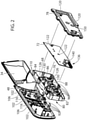
- FIG. 2 front panel 48, a box / receptacle 68, an electronic board 72 and a cover 78 are shown in an explosive view.
- Box 68 is a receptacle which in an assembled state receives electronic board 72.
- cover 78 is closing box 68.
- Box 68 comprises a front wall 80 which in the assembled state faces front panel 48 and four adjacent side walls 82, 84, 86, 88.
- Front panel 48 preferably comprises openings or holes or depressions 92 which in the assembled state receive protrusions 96 of box 68 which house touch contacts of touch sensors of touch switches which are arranged on board 72.
- Front panel 48 preferably comprises snap means 102 for attaching front panel 48 to the casing 6 of laundry treatment appliance 2.
- Snap means 106 are preferably provided on front panel 48 which engage with corresponding snap means 110 on box 68.
- domes 116 for insertion of fixing means which in the present preferred embodiment are screws
- these screws are preferably guided first through openings 120 in cover 78 and subsequently through openings 122 in board 72, which are built as domes with holes, and openings 130 of domes 126 on box 68.
- the screws then reach into domes 116 of front panel 48 which, respectively, comprise an inner thread into which the respective screw with an outer thread is screwed.
- the box 68 is preferably attached to front panel 48 by engaging of snap means 106 on front panel 48 with snap means 110 on box 68.
- the electronic board 72 is preferably attached to box 68 by snap means 76. Then the box 68 is closed by cover 78, thereby closing the internal space of box 68 in which electronic board 72 is arranged. Then, as the last assembly step, the same screws are then passed through these four components. Therefore, the same fixing means or connection means are used to for front panel 48, box 68, board 72 and cover 78, which yields an especially convenient and simple way to attach these components in a removable way.
- connection By the described connection between front panel 48, box 68 and cover 78, a connection is provided which only requires few and simple connection means and is removable.
- the electronic board 72 is housed in box 68 which is closed by cover 78.
- the cover 78 is detachable from box 68 by loosening the above described screws; the electronic board 72 can easily be removed and repaired or replaced.
- Snap means 76 are preferably provided at the internal periphery of box 68 for engagement of box 68 with electronic board 72, thereby spatially fixing the electronic board 72 with respect to box 68.
- Board 72 preferably comprises a first group of contacts 136 which are located at the periphery of board 72. Board 72 preferably further comprises a connector cage 140 in which a second group of contacts is provided.
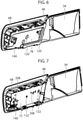
- FIG. 3 in a rear view, front panel 48, box 68, board 72 and cover 78 are shown in an assembled state in a rear view.
- Cover 78 of which a rear side 74 is shown comprises openings 120 which respectively receive screws.
- Cover 78 preferably comprises an opening 160 through which the contacts which are arranged within connector cage 140 are accessible.
- FIG. 4 a section along line A-A of FIG. 3 is shown, and in FIG. 5 , an enlarged view of components drawn in a circle 164 in FIG 4 is shown.
- Snap means 76 are provided on cover 78 for the electronic board engagement and snap means 110 on frontal plate 48 are visible
- cover 78 The connection between cover 78 and box 68 is made in such a way that the electronic board 72 is at least partially protected from water, steam or contaminating particles which can be present in laundry treatment appliance 2. This is achieved by a sealing element which is provided on cover 78 and which a gasket 180 made preferably of rubber.
- Cover 78 preferably comprises at its periphery a frame 186 with two parallel shoulders 190, 192 which are perpendicular to a center plate 194 of cover 78 and between which a groove 196 is formed.
- shoulder 190 is an outer shoulder
- shoulder 192 is an inner shoulder and is located closer to a center of cover 78.
- Gasket 180 is co-molded to cover 78 and is preferably located within groove 196. Gasket 180 also covers shoulder 190. In the assembled state, the gasket 180 is in contact with box 68 and in this way acts as a sealing element. Groove 196 and gasket 180 are preferably arranged along the whole periphery of cover 78, thereby provided a fully sealed connection between box 68 and cover 78 and reliably preventing steam, water or particles to enter box 68 and to lead to malfunctions or defects of electronic board 72.
- gasket 180 is provided only partially along the periphery of cover 78, which means that not necessarily all sides of the periphery are provided with a gasket 180 and/or on one or more sides the gasket 180 is not provided over the whole length of the side.
- cover 78 and box 68 are built or designed in such a way that connecting parts without gasket 180 already provide reliable protection against steam, water or particles.
- pins 206, 208 are provided which in the assembled state reach through corresponding holes in board 72 and lead to further stabilization of the assembly.
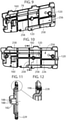
- FIG. 8 a cross section of front panel 48, box 68 and cover 78 is shown.
- outer shoulder 190 is preferably wider or broader than an opposing side 216.
- gasket tracks 220 are provided which are discussed below.
- a bore 226 or hole is provided on front panel 48 for inserting a screw. Bore 226 comprises an inner thread which engages with an outer thread of the screw.
- the screw is lead inserted in an insertion direction 232 through an opening in a dome 182 provided on cover 78 and subsequently through an opening in a dome 126 provided on box 68.
- a corresponding hole or opening 122 is provided on electronic board 72 through which the screw is lead.
- a light guide 300 is provided between electronic board 72 and box 68 for guiding light emitted from light elements provided on electronic board 72 to the front panel 48. These light elements on board 72 are preferably LEDS.
- FIG. 9 a rear side 256 of cover 78 is shown in an isomeric view and in FIG. 10 in a frontal view.
- rear side 256 is opposite to a front side of cover 78 which faces electronic board 72.
- ribs 258 are seen which are preferably behind the gasket tracks 220 on the front side of cover 78.
- Cover 78 comprises an opening 160 for a connector cage.
- FIG. 11 a cut through cover 78 along the line B-B shown in FIG. 10 is shown, of which a part encircled by a circle is shown in FIG. 12 .
- a through hole 228 reaching through to the groove 196 serves to improve the fixation of the gasket on the cover 78 by sticking to both components.
- the respective opening 120 is surrounded by a dome 182.
- a gasket 188 is provided on dome 182, on its side which in the assembled state faces electronic board 72. This gasket 188 provides a frontal sealing effect, preventing water, moisture or particles to pass between electronic board 72 and gasket 188.
- FIG. 14 the front side of cover 78 which in the assembled state faces electronic board 72 is shown in a perspective view. Gasket tracks 226 are shown which lead liquid material which is injected in an injection point 280.
- Opening 160 which in an assembled state allows access to the connector cage 140 is surrounded by a gasket 270 which seals the connection or interface region between gasket connector cage and cover 78.
- the opening 160 has preferably a rectangular shape.
- Gasket 270 is preferably formed with a frontal lip 271, a back lip 273 and two side lips 275, 277. The length or extension of all lips 271, 273, 275, 277 are dimensioned to provide a sealed connection to connector cage 140, preventing in the assembled state for moisture or particles to enter through gaps between gasket 270 and connector cage 140.
- the invention also concerns a cover 78 which comprises gasket 270 but without the peripheral gasket 180.
- the gasket 180 and preferably also the gasket 270 are produced in the same co-molding process in which liquid material is injected in at least one injection point 280 and is by running through gasket tracks 226 and is distributed in grooves to form the gaskets 180, 270.
- electronic board 72 in a first preferred embodiment is shown.
- several spring contacts 284 are provided which can be activated on the user interface provided on front panel 48.
- several light elements 324, 326 are provided which are preferably built as LEDs.
- a top frame 300 is shown which is mounted on board 72.
- Frame 300 is an additional component which preferably serves especially to house light guided in channels 330 which transmit light emitted from corresponding light elements on board 72 to the user interface.
- Frame 300 preferably comprises a display unit 320.
- Frame 300 and a board 72 in an assembled state are shown in FIG. 18 .
- the display unit 320 is illuminated by light elements 324 on electronic board 72.
- the display unit 320 is preferably used to indicate status information to the user, for instance the selected treatment program and/or parameters thereof and/or a corresponding status.
- An opening 340 allows the passage of dome 126 on box 68 during assembly.
- the household appliance 2 is according the invention manufactured as follows.
- the electronic board 72 is placed inside the box 68.
- the cover 78 is placed in a mold, and a gasket 180 is co-molded to cover 78 in such a way that a sealing connection between box 69 and cover 78 is achieved in the assembled state.
- the gasket 180 is preferably over-injected in cover 78.
- the box is closed by the cover 78.
- the at least one at least at least partially circumferential groove 196 is provided.
- the material to be co-molded in the liquid state then can flow from the injection point 280 into the groove 196, preferably by gasket tracks 220 or connecting tracks.
Description
- The invention generally relates to a household appliance. The invention more particularly relates to household appliance comprising an electronic board. The invention furthermore relates to a method for manufacturing a household appliance.
- Known household appliances such as laundry machines, i.e. washing machines, driers, and combined washer/driers, are usually provided with a user interface comprising a dashboard or control panel with input devices, knobs, buttons, etc., allowing the user to select or set washing and/or drying programs. The dashboards are typically provided also with output devices such as displays, LEDs, etc. for giving a feedback to the user related to the settings/status of the machine.
- Some of these dashboards are provided with capacitive touch sensitive input devices that detect the contact of the user by means of capacitive change. An electronic board, which can comprise controls to be operated on the user interface, is provided for, as way of example, receiving the user input, sending signals to a display to show information to the user on the current running or selected program and/or parameters thereof, and to operate valves for water supply or drain, to operate a motor for rotating a drum etc.
- In order to ensure proper operation of the electronic board and to arrange it close to the user interface, it can be arranged in a receptacle which is then closed by a cover.
- Disadvantageous of such a solution is the difficult replacement of the electronic board.
- The
EP 2 876 196 A1 discloses a household appliance with a front panel, whereby on the rear side of the front panel a receptacle is arranged which receives an electronic board. A cover for closing the receptacle is not provided thus the electronic board can be subject to moist, steam, water or particles which can lead to malfunctioning of the electronic board. - Document
EP 1 176 619 A2 discloses an electronic operating unit for an household appliance comprising an electronic holder connected on the rear side with an electronic board and on the front side with a keyboard; the keyboard is assembled on a recess provided on the electronic holder, and is covered by a flat cover. DocumentDE 202 10 107 U1 discloses a display assembly comprising a frame on which an electronic board is assembled; a display is assembled on the electronic board, so that when the board and the frame are assembled, said display is visible through an opening provided on said frame; around said opening a sealing element is provided to assure a sealing effect between the frame and a view window of the machine control panel. - Document
EP 3 162 947 (prior art in the sense of Art. 54(3) EPC) discloses a door for a laundry treating apparatus with a door frame and an opening portion corresponding to a display module mounted at an inside - Document
US 5 748 270 discloses an LCD assembly including a frame housing an LCD material layered on an electroluminescent material layered on a circuit board. One side of the circuit board includes elastomeric connectors to connect to, respectively, the LCD material and the electroluminescent material on the other side of the circuit board, a third elastomeric connector attaches to the main circuit board of a consumer product. -
Document EP 2 837 726 discloses a laundry treatment device comprising: a casing including a front wall having a panel aperture and an abutment surface at an edge (of the panel aperture; a control panel assembly with an outer dashboard coupled to the panel aperture, and a sealing element interposed between the outer dashboard and the abutment surface at the edge of the panel aperture. -
- The aim of the invention is to provide a household appliance with at least one control circuit board comprising peripheral contacts that is easy to replace and reliably protected against moist and dirt.
- Another aim of the invention is to provide a household appliance which is easy to assemble and has an optimized reduced number of components.
- Another aim of the invention is to provide a method for assembling a household appliance.
- In a first aspect, the invention relates to a household appliance according to claim 1.
- Applicant has found that a reliable protection of the electronic board can be achieved by providing fixing means for connecting receptacle and cover and by providing a sealing element which seals the connection between receptacle and cover. Preferably, the fixing means provide a removable connection between the receptacle and the cover. This allows an easy replacement of the electronic board in a convenient and a non-destructive way. In this way, malfunctions of the board due to humidity or contaminating are prevented in the first place. If, however, the board needs to be replaced, this can be performed in a convenient and non-destructive way.
- A sealed connection denotes especially a connection which seals against water/steam/humidity/contaminating particles as they occur within or in the periphery of a household appliance during operation.
- The receptacle is preferably built as a box and/or has essentially a box-like shape, especially at least one face wall and for orthogonal side walls.
- The sealing element is arranged on the cover.
- This configuration has advantages over the previous one during manufacturing, since the cover typically is a smaller component than the receptacle, the corresponding machine/mold for providing the sealing element on the cover can be dimensioned smaller.
- The sealing element is a gasket which is co-molded to the cover. In this way, a robust and tight connection between gasket and cover can be achieved, yielding good sealing properties. The gasket is preferably made of rubber.
- The cover at its periphery advantageously comprises a groove, whereby the gasket is positioned at least partially inside the groove. In this way, a force fit and/or form-locking connection between gasket and cover is established. Additionally, the gasket is partly located inside the cover, allowing a compact design of the cover.
- Preferably, the cover at its periphery comprises a frame from which two parallel shoulders protrude which form this groove between them, whereby the gasket is positioned at least partially inside the groove and covers at least one of these shoulders, whereby in the assembled state the gasket is arranged between at least one shoulder and a side surface of the receptacle, thereby sealing the connection between the receptacle and the cover.
- The cover preferably comprises a frontal side which in an assembled state faces the electronic board, and a back side opposed to said frontal side, and wherein on the cover on the frontal side gasket tracks are provided which in an assembled state face the electronic board. These tracks are preferably built as grooves or channels which during a molding process allow the liquid material to flow into regions where the gasket should be co-molded to the cover and possibly other parts of the cover where the material is needed.
- The cover preferably comprises a frontal side which in an assembled state faces the electronic board and a back side, wherein the cover on said frontal side comprises least one at least partially circumferential groove and an injection point for the molding material which is connected to at least one track through which material when injected in a liquid state in said injection point is allowed to flow.
- At least one connecting groove is advantageously provided from the injection point to the at least one at least partially circumferential groove, and whereby material when injected in a liquid state in the injection point is allowed to flow into the at least one at least partially circumferential groove.
- Advantageously, the cover comprises at least one hole for insertion of fixing means. These fixing means are advantageously screws.
- The receptacle comprises at least one dome/protrusion for insertion of a screw, whereby the electronic board comprises at least one hole, and whereby the cover comprises at least one opening, whereby the dome, the hole and the opening are axially aligned in an assembled state so that a fixing element is lead through the opening, the hole and through the dome. The fixing element is preferably a screw. Alternatively, it can be a pin or snap means.
- The opening is preferably surrounded by a dome. In other words, a dome is provided on the cover with the opening inside.
- Advantageously holes are provided on said cover in the domes. These holes preferably respectively comprise an inner thread which fits with a respective outer thread of the corresponding screw.
- Preferably, the household appliance comprises a frontal plate or face plate, whereby a removable connection between the receptacle and the faceplate is provided. This connection is preferably achieved by a snap connection, whereby snap elements, especially snap teeth, are provided on receptacle and/or faceplate which engage with corresponding receiving elements on the other part.
- The frontal plate preferably comprises a front side and a rear side facing the interior of said household appliance and which in an assembled state faces the receptacle, whereby on the rear side at least one fixing means, especially for insertion of a screw, is provided.
- The face plate advantageously comprises a user interface. The user interface preferably comprises at least one user interface element with which the user can operate with the machine and preferably a least one display element and/or light element for indicating status information on the current status of the appliance.
- The electronic board preferably comprises a connector cage encompassing at least one contact, and whereby a connector sealing element is provided on the cover which at least partially in a sealing manner encompasses the connector cage.
- The connector sealing element is a gasket which is co-molded to the cover.
- The connector sealing element advantageously comprises a frontal lip and a rear lip and two side lips, whereby the frontal and rear lips, respectively, have the length of corresponding sides of the connector cage.
- The length of the respective side lip thereby preferably equals to the length of the adjacent side of the connector cage. In this way, a sealed connection at the connector cage is provided, preventing steam or water or particles to reach the inside of the receptacle and to reach the side of the electronic board which faces the frontal plate of the appliance. In this way damage of the electronic board can be prevented. In an alternate embodiment, the length of the respective side lip exceeds the length of the adjacent side of the connector cage. This design allows using the same cover for electronic boards with different lengths of the connector cage.
- Preferably a removable connection is provided between the electronic board and the cover.
- In a second aspect, the present invention relates to a method for manufacturing a household appliance according to claim 11.
- In a preferred embodiment, the cover comprises at least one at least partially circumferential groove and an injection point for the molding material, whereby at least one connecting track, especially a groove, is provided from the injection point to the at least one at least partially circumferential groove, and whereby material in a liquid state is injected in the injection point and allowed to flow into the at least one at least partially circumferential groove.
- This design of the cover allows the liquid material to flow from the injection point through the tracks and to reach all regions in which the gasket is to be formed, The gasket by this method is therefore actively formed.
- The cover preferably comprises at least one through-point, and whereby during molding, gasket material is allowed to flow into the through-point. The through-point is preferably a channel or opening in the cover.
- The advantages of the invention are especially as follows. The sealing element simultaneously seals all important parts between the cover and the electronic board and thereby provides a reliable protection of the electronic board from steam, water or contaminating particles. In this way, the proper functioning of the appliance is enabled and the lifetimes of these electronic components and also of the whole appliance are prolonged.
- The combination of the electronic board, the box, the faceplate and the cover offers a great simplicity of the assembly. Only a few pieces are needed, and only few connection means are needed to firmly and securely connect these components.
- Further features and advantages of the present invention shall become clearer from the following detailed description of some of its preferred embodiments, made with reference to the attached schematic drawings and given as an indication and not for limiting purposes.
- In particular, the attached drawings are included to provide a further understanding of the invention and are incorporated in and constitute a part of this specification. The drawings together with the description explain the principles of the invention. In the drawings, corresponding characteristics and/or components are identified by the same reference numbers. In these drawings:
- FIG. 1
- shows a laundry treatment appliance with a front panel in a preferred embodiment;
- FIG. 2
- shows an explosive view of the front panel of according to
FIG. 1 , a box, an electronic board and a box cover; - FIG. 3
- shows a rear view of front panel, box, electronic board and cover in an assembled state;
- FIG. 4
- shows the assembly according to
FIG. 3 in cross-sectional view along line A-A; - FIG. 5
- shows an enlarged partial view of
FIG. 4 ; - FIG. 6
- shows an isometric rear view of the assembly of front panel, box, electronic board and cover with the cover attached;
- FIG. 7
- shows an isometric rear view of the assembly with the cover removed;
- FIG. 8
- shows a cross-sectional view of the assembly;
- FIG.9
- shows a perspective rear view of the cover;
- FIG. 10
- shows a rear view of the cover;
- FIG. 11
- shows a cross-sectional view of the cover according to
FIG.10 along line B-B; - FIG. 12
- shows an enlarged view of
FIG. 11 ; - FIG. 13
- shows a rear view of the cover assembled to the box;
- FIG. 14
- shows a front view of the cover;
- FIG. 15
- shows a cross sectional view of the assembly according to
FIG. 13 along line C-C; - FIG. 16
- shows an electronic board according to the invention;
- FIG. 17
- shows a top frame for housing light guides; and
- FIG. 18
- shows the electronic board according to
FIG. 16 with the frame according toFIG. 17 attached. - Same parts are labelled by identical reference numerals.
- In
FIG. 1 , alaundry treatment appliance 2 is shown which is built as a front-loading washing machine and comprises a housing orcasing 6 with a preferable parallelepiped shape, thecasing 6 comprising afront wall 10, twoside walls 14, acover plate 20 and a rear wall (not shown).Front wall 10 andside walls 14 are preferably part of a cabinet. Afront door 24 is provided which can be opened for loading or unloading laundry through an opening into a washing drum. - Advantageously a washing tub is contained within
casing 6, whereby a rotatable and perforated drum is contained by said washing tub. Both washing tub and drum have a substantially cylindrical shape. Advantageously the tub is suspended in a floating manner insidecasing 6 by means of a number of coil springs and shock absorbers. The drum is rotated by an electric motor (not shown), which transmits the rotating motion of a motor shaft to the drum by a belt/pulley system. In a different embodiment of the invention, the motor can be directly associated with the shaft of the drum. The tub is preferable connected tocasing 6 by means of an elastic bellows or gasket. Alternatively, the laundry appliance can be a dryer (in which case the tub is not provided) or a combined washer and dryer. - The preferred washing machine shown in
FIG.1 on afront panel 48 comprises adrawer 30 with afront plate 34 and ahandle 38 for pulling out and pushing back indrawer 30.Drawer 30 comprises at least one compartment for detergent or washing additives. Adjacent todrawer 30, auser interface 50 is provided. Onuser interface 50, preferably aswitch 56 is provided for switching on/offappliance 2. Preferably,user interface elements 60 such as, for example, touch buttons, light elements, display elements, are provided. - In
FIG. 2 ,front panel 48, a box /receptacle 68, anelectronic board 72 and acover 78 are shown in an explosive view.Box 68 is a receptacle which in an assembled state receiveselectronic board 72. In the assembled state, cover 78 is closingbox 68.Box 68 comprises afront wall 80 which in the assembled state facesfront panel 48 and fouradjacent side walls -
Front panel 48 preferably comprises openings or holes ordepressions 92 which in the assembled state receiveprotrusions 96 ofbox 68 which house touch contacts of touch sensors of touch switches which are arranged onboard 72. -
Front panel 48 preferably comprises snap means 102 for attachingfront panel 48 to thecasing 6 oflaundry treatment appliance 2. Snap means 106 are preferably provided onfront panel 48 which engage with corresponding snap means 110 onbox 68. - For the connection of
front panel 48,box 68 and cover 78 in the assembled state, onfront panel 48 twodomes 116 for insertion of fixing means, which in the present preferred embodiment are screws, are preferably provided. For the assembly offrontal panel 48,box 68,board 72 andcover 78, these screws are preferably guided first throughopenings 120 incover 78 and subsequently throughopenings 122 inboard 72, which are built as domes with holes, andopenings 130 ofdomes 126 onbox 68. The screws then reach intodomes 116 offront panel 48 which, respectively, comprise an inner thread into which the respective screw with an outer thread is screwed. - The
box 68 is preferably attached tofront panel 48 by engaging of snap means 106 onfront panel 48 with snap means 110 onbox 68. Theelectronic board 72 is preferably attached tobox 68 by snap means 76. Then thebox 68 is closed bycover 78, thereby closing the internal space ofbox 68 in whichelectronic board 72 is arranged. Then, as the last assembly step, the same screws are then passed through these four components. Therefore, the same fixing means or connection means are used to forfront panel 48,box 68,board 72 andcover 78, which yields an especially convenient and simple way to attach these components in a removable way. - By the described connection between
front panel 48,box 68 andcover 78, a connection is provided which only requires few and simple connection means and is removable. Theelectronic board 72 is housed inbox 68 which is closed bycover 78. - Since this connection is removable, the
cover 78 is detachable frombox 68 by loosening the above described screws; theelectronic board 72 can easily be removed and repaired or replaced. Snap means 76 are preferably provided at the internal periphery ofbox 68 for engagement ofbox 68 withelectronic board 72, thereby spatially fixing theelectronic board 72 with respect tobox 68. -
Board 72 preferably comprises a first group ofcontacts 136 which are located at the periphery ofboard 72.Board 72 preferably further comprises aconnector cage 140 in which a second group of contacts is provided. - In
FIG. 3 , in a rear view,front panel 48,box 68,board 72 and cover 78 are shown in an assembled state in a rear view.Cover 78 of which arear side 74 is shown comprisesopenings 120 which respectively receive screws.Cover 78 preferably comprises anopening 160 through which the contacts which are arranged withinconnector cage 140 are accessible. - In
FIG. 4 , a section along line A-A ofFIG. 3 is shown, and inFIG. 5 , an enlarged view of components drawn in acircle 164 inFIG 4 is shown. Snap means 76 are provided oncover 78 for the electronic board engagement and snap means 110 onfrontal plate 48 are visible - The connection between
cover 78 andbox 68 is made in such a way that theelectronic board 72 is at least partially protected from water, steam or contaminating particles which can be present inlaundry treatment appliance 2. This is achieved by a sealing element which is provided oncover 78 and which agasket 180 made preferably of rubber.Cover 78 preferably comprises at its periphery aframe 186 with twoparallel shoulders center plate 194 ofcover 78 and between which agroove 196 is formed. In particular,shoulder 190 is an outer shoulder andshoulder 192 is an inner shoulder and is located closer to a center ofcover 78. -
Shoulder 192 has a smaller extension in a direction towardsfront panel 48.Gasket 180 is co-molded to cover 78 and is preferably located withingroove 196.Gasket 180 also coversshoulder 190. In the assembled state, thegasket 180 is in contact withbox 68 and in this way acts as a sealing element. Groove 196 andgasket 180 are preferably arranged along the whole periphery ofcover 78, thereby provided a fully sealed connection betweenbox 68 andcover 78 and reliably preventing steam, water or particles to enterbox 68 and to lead to malfunctions or defects ofelectronic board 72. In an alternative preferred embodiment,gasket 180 is provided only partially along the periphery ofcover 78, which means that not necessarily all sides of the periphery are provided with agasket 180 and/or on one or more sides thegasket 180 is not provided over the whole length of the side. This variant is advantageous ifcover 78 andbox 68 are built or designed in such a way that connecting parts withoutgasket 180 already provide reliable protection against steam, water or particles. Onbox 68, pins 206, 208 are provided which in the assembled state reach through corresponding holes inboard 72 and lead to further stabilization of the assembly. - In
FIG. 8 , a cross section offront panel 48,box 68 and cover 78 is shown. On afirst side 212,outer shoulder 190 is preferably wider or broader than an opposingside 216. Oncover 78, gasket tracks 220 are provided which are discussed below. Abore 226 or hole is provided onfront panel 48 for inserting a screw.Bore 226 comprises an inner thread which engages with an outer thread of the screw. - The screw is lead inserted in an
insertion direction 232 through an opening in adome 182 provided oncover 78 and subsequently through an opening in adome 126 provided onbox 68. A corresponding hole oropening 122 is provided onelectronic board 72 through which the screw is lead. - A
light guide 300 is provided betweenelectronic board 72 andbox 68 for guiding light emitted from light elements provided onelectronic board 72 to thefront panel 48. These light elements onboard 72 are preferably LEDS. - In
FIG. 9 , arear side 256 ofcover 78 is shown in an isomeric view and inFIG. 10 in a frontal view. In an assembled state,rear side 256 is opposite to a front side ofcover 78 which faceselectronic board 72. Onrear side 256,ribs 258 are seen which are preferably behind the gasket tracks 220 on the front side ofcover 78.Cover 78 comprises anopening 160 for a connector cage. - In
FIG. 11 , a cut throughcover 78 along the line B-B shown inFIG. 10 is shown, of which a part encircled by a circle is shown inFIG. 12 . A throughhole 228 reaching through to thegroove 196 serves to improve the fixation of the gasket on thecover 78 by sticking to both components. As can be seen inFIG. 14 , therespective opening 120 is surrounded by adome 182. Ondome 182, on its side which in the assembled state faceselectronic board 72, agasket 188 is provided. Thisgasket 188 provides a frontal sealing effect, preventing water, moisture or particles to pass betweenelectronic board 72 andgasket 188. - In
FIG. 14 , the front side ofcover 78 which in the assembled state faceselectronic board 72 is shown in a perspective view. Gasket tracks 226 are shown which lead liquid material which is injected in aninjection point 280. - Opening 160 which in an assembled state allows access to the
connector cage 140 is surrounded by agasket 270 which seals the connection or interface region between gasket connector cage andcover 78. Theopening 160 has preferably a rectangular shape.Gasket 270 is preferably formed with afrontal lip 271, aback lip 273 and twoside lips lips connector cage 140, preventing in the assembled state for moisture or particles to enter through gaps betweengasket 270 andconnector cage 140. - In this way, simultaneously the connectors located inside
connector cage 140 are accessible and this connection region is sealed against steam, water and other particles, avoiding them to enter thebox 68 and possibly leading to malfunctions or defects ofelectronic board 72. The invention also concerns acover 78 which comprisesgasket 270 but without theperipheral gasket 180. - The
gasket 180 and preferably also thegasket 270 are produced in the same co-molding process in which liquid material is injected in at least oneinjection point 280 and is by running throughgasket tracks 226 and is distributed in grooves to form thegaskets - In
FIG. 16 electronic board 72 in a first preferred embodiment is shown. Onboard 72,several spring contacts 284 are provided which can be activated on the user interface provided onfront panel 48. Onboard 72, severallight elements - In
FIG. 17 , atop frame 300 is shown which is mounted onboard 72.Frame 300 is an additional component which preferably serves especially to house light guided inchannels 330 which transmit light emitted from corresponding light elements onboard 72 to the user interface.Frame 300 preferably comprises adisplay unit 320.Frame 300 and aboard 72 in an assembled state are shown inFIG. 18 . Thedisplay unit 320 is illuminated bylight elements 324 onelectronic board 72. Thedisplay unit 320 is preferably used to indicate status information to the user, for instance the selected treatment program and/or parameters thereof and/or a corresponding status. Anopening 340 allows the passage ofdome 126 onbox 68 during assembly. Thehousehold appliance 2 is according the invention manufactured as follows. Theelectronic board 72 is placed inside thebox 68. Before this step or afterwards or simultaneously, thecover 78 is placed in a mold, and agasket 180 is co-molded to cover 78 in such a way that a sealing connection between box 69 and cover 78 is achieved in the assembled state. Thegasket 180 is preferably over-injected incover 78. Finally, the box is closed by thecover 78. - In order to facilitate the over-injection process, preferably the at least one at least at least partially
circumferential groove 196 is provided. The material to be co-molded in the liquid state then can flow from theinjection point 280 into thegroove 196, preferably bygasket tracks 220 or connecting tracks. - The invention thus conceived can be subjected to numerous modifications and variants all falling within the scope of the inventive concept. In practice, all the materials used, as well as the shapes and contingent dimensions, may vary depending on the requirements without departing from the scope of protection of the following claims.
Claims (13)
- Household appliance (2), comprising an electronic board (72) and a receptacle (68) which receives said electronic board (72), further comprising a cover (78) configured to close said receptacle (68), whereby said cover (78) in an assembled state is connected to said receptacle (68), fixing means are provided for a connection between said receptacle (68) and said cover (78), and whereby a sealing element (180) is configured to provide a sealed connection between said receptacle (68) and said cover (78) in an assembled state, whereby the electronic board is placed inside the receptacle and the receptacle is closed by the cover;
characterized in that said sealing element (180) is arranged on said cover (78), whereby said sealing element (180) is a gasket which is co-molded to said cover (78). - Household appliance (2) according to claim 1, whereby said fixing means provide a removable connection between said receptacle (68) and said cover (78).
- Household appliance (2) according to claim 1 or 2, whereby said cover (78) at its periphery comprises a groove (196), and whereby said gasket (180) is positioned at least partially inside said groove (196).
- Household appliance (2) according to claim 1 or 3, whereby said cover (78) comprises a frontal side which in an assembled state faces said electronic board (72) and a back side opposed to said frontal side, and wherein on said cover (78) on said frontal side gasket tracks are provided which in an assembled state face said electronic board (72).
- Household appliance according to claim 4, whereby said cover (78) at its periphery comprises a frame (186) from which two parallel shoulders (190, 192) protrude which form said groove (196) between them, and whereby said gasket (180) is positioned at least partially inside said groove (196) and covers at least one of said shoulders (192), whereby in the assembled state said gasket (180) is arranged between at least one shoulder (192) and a side surface of said receptacle (68), thereby sealing the connection between said receptacle (68) and said cover (78).
- Household appliance (2) according to one of the claims 1 to 5, whereby said receptacle (68) comprises at least one dome (130) for insertion of a screw, and whereby said electronic board (72) comprises at least one hole (122), and whereby said cover (78) comprises at least one opening (120), whereby said dome (130), said hole (122) and said opening (120) are axially aligned in an assembled state so that a fixing element is lead through said opening (120) and said hole (122) and through said dome (130).
- Household appliance (2) according to one of the claims 1 to 6, comprising a faceplate (48), whereby a removable connection between said receptacle (68) and said faceplate (48) is provided.
- Household appliance (2) according to claim 7, whereby said faceplate (48) comprises a user interface.
- Household appliance (2) according to one of the claims 1 to 8 whereby said electronic board (72) comprises a connector cage (140) encompassing at least one contact, and whereby a connector sealing element (270) is provided on said cover which at least partially in a sealing manner encompasses said connector cage (140).
- Household appliance (2) according to claim 9, whereby said connector sealing element (270) is a gasket co-molded to said cover (78).
- Method for manufacturing a household appliance (2), whereby said appliance (2) comprises an electronic board (72), a receptacle (68) for receiving said electronic board (72) and a cover (78) configured to close said receptacle (68), whereby said electronic board (72) is placed inside said receptacle (68) and said receptacle (68) is closed by said cover (78), characterized in that before closing said receptacle (68) by said cover (78), said cover (78) is placed in a mold, and a gasket (180) is co-molded on said cover (78) in such a way that it provides a sealing connection between said receptacle (68) and said cover (78) in their assembled state.
- Method according to claim 11, whereby said cover (78) comprises at least one at least partially circumferential groove and an injection point for the molding material, whereby at least one connecting track is provided from said injection point to said at least one at least partially circumferential groove, and whereby material in a liquid state is injected in said injection point and allowed to flow into said at least one at least partially circumferential groove.
- Method according to claim 11 or 12, whereby said cover (78) comprises at least one through-point, and whereby during molding, gasket material is allowed to flow into said through-point.
Priority Applications (4)
| Application Number | Priority Date | Filing Date | Title |
|---|---|---|---|
| PL15202987T PL3187647T3 (en) | 2015-12-29 | 2015-12-29 | Household appliance with an electronic board and method for manufacturing a household appliance |
| EP15202987.2A EP3187647B1 (en) | 2015-12-29 | 2015-12-29 | Household appliance with an electronic board and method for manufacturing a household appliance |
| US16/064,080 US10954619B2 (en) | 2015-12-29 | 2016-12-07 | Household appliance with an electronic board and method for manufacturing a household appliance |
| PCT/EP2016/079977 WO2017114642A1 (en) | 2015-12-29 | 2016-12-07 | Household appliance with an electronic board and method for manufacturing a household appliance |
Applications Claiming Priority (1)
| Application Number | Priority Date | Filing Date | Title |
|---|---|---|---|
| EP15202987.2A EP3187647B1 (en) | 2015-12-29 | 2015-12-29 | Household appliance with an electronic board and method for manufacturing a household appliance |
Publications (2)
| Publication Number | Publication Date |
|---|---|
| EP3187647A1 EP3187647A1 (en) | 2017-07-05 |
| EP3187647B1 true EP3187647B1 (en) | 2022-02-23 |
Family
ID=55027538
Family Applications (1)
| Application Number | Title | Priority Date | Filing Date |
|---|---|---|---|
| EP15202987.2A Active EP3187647B1 (en) | 2015-12-29 | 2015-12-29 | Household appliance with an electronic board and method for manufacturing a household appliance |
Country Status (4)
| Country | Link |
|---|---|
| US (1) | US10954619B2 (en) |
| EP (1) | EP3187647B1 (en) |
| PL (1) | PL3187647T3 (en) |
| WO (1) | WO2017114642A1 (en) |
Families Citing this family (7)
| Publication number | Priority date | Publication date | Assignee | Title |
|---|---|---|---|---|
| CN111851003B (en) * | 2019-04-28 | 2022-05-24 | 青岛海尔洗衣机有限公司 | Upper cover of clothes treatment equipment and clothes treatment equipment |
| CN111979697A (en) * | 2019-05-23 | 2020-11-24 | 博西华电器(江苏)有限公司 | Laundry treating machine and control panel assembly thereof |
| CN112064296A (en) * | 2019-05-23 | 2020-12-11 | 博西华电器(江苏)有限公司 | Laundry treating machine and control panel assembly thereof |
| EP3795733B1 (en) * | 2019-09-17 | 2024-01-10 | Girbau, S.A. | Washing machine with status indication |
| TWI717172B (en) * | 2019-12-26 | 2021-01-21 | 台灣松下電器股份有限公司 | Waterproof touch panel device |
| CN116368950A (en) * | 2021-03-04 | 2023-06-30 | 三星电子株式会社 | Washing machine and clothes care device |
| CN115772776A (en) * | 2021-09-07 | 2023-03-10 | 青岛海尔洗衣机有限公司 | Tray seat device of clothes treatment equipment and clothes treatment equipment |
Citations (4)
| Publication number | Priority date | Publication date | Assignee | Title |
|---|---|---|---|---|
| US5748270A (en) * | 1996-06-25 | 1998-05-05 | Ericsson, Inc. | LCD with electroluminescent backlighting |
| EP2837721A1 (en) * | 2013-08-13 | 2015-02-18 | Electrolux Appliances Aktiebolag | Laundry appliance provided with a control-panel assembly |
| EP2837726A1 (en) * | 2013-08-13 | 2015-02-18 | Electrolux Appliances Aktiebolag | A laundry treatment device having a control panel assembly |
| EP3162947A1 (en) * | 2015-11-02 | 2017-05-03 | LG Electronics Inc. | Laundry treating apparatus |
Family Cites Families (17)
| Publication number | Priority date | Publication date | Assignee | Title |
|---|---|---|---|---|
| JP2875327B2 (en) * | 1990-03-02 | 1999-03-31 | 株式会社日立製作所 | Liquid crystal display |
| DE19651821C2 (en) * | 1996-12-13 | 2003-04-03 | Miele & Cie | Laundry or dishwasher |
| JP3919982B2 (en) * | 1999-09-30 | 2007-05-30 | 株式会社日立製作所 | Liquid crystal display device and liquid crystal display monitor |
| DE20013019U1 (en) * | 2000-07-27 | 2001-12-20 | Liebherr Hausgeraete | Electronics control unit |
| KR100840235B1 (en) * | 2001-08-29 | 2008-06-20 | 삼성전자주식회사 | Liquid crystal display device |
| EP1495176B1 (en) * | 2002-04-17 | 2011-02-09 | LG Electronics, Inc. | Washer |
| DE20210707U1 (en) * | 2002-07-11 | 2003-11-20 | Diehl Ako Stiftung Gmbh & Co | Backlit liquid crystal display, especially for use as a display module behind the control panel of a large household appliance |
| DE10344918B4 (en) * | 2003-09-17 | 2009-12-17 | Prettl Appliance Systems Gmbh | Iris arrangement for a household machine |
| DE102004048755B4 (en) * | 2004-10-05 | 2008-03-27 | Miele & Cie. Kg | Domestic appliance, in particular laundry treatment machine such as washing machine, washer-dryer or tumble dryer with a control panel |
| JP5080493B2 (en) * | 2005-12-23 | 2012-11-21 | エルジー エレクトロニクス インコーポレイティド | Washing machine |
| EP2380479A1 (en) * | 2010-04-23 | 2011-10-26 | Miele & Cie. KG | Operating device for domestic appliances such as ovens, steam cookers, washing machines or dishwashers |
| EP2458060B1 (en) * | 2010-11-29 | 2016-02-17 | Electrolux Home Products Corporation N.V. | Control-panel assembly for household appliances and household appliance provided with such control-panel assembly |
| PL2837729T3 (en) * | 2013-08-13 | 2017-06-30 | Electrolux Appliances Aktiebolag | A laundry treatment device having a control panel assembly |
| EP2876196A1 (en) | 2013-11-21 | 2015-05-27 | Electrolux Appliances Aktiebolag | Household appliance provided with a control panel |
| US10367538B2 (en) * | 2014-04-11 | 2019-07-30 | Catalyst Lifestyle Limited | Waterproof case |
| KR102202721B1 (en) * | 2015-02-25 | 2021-01-13 | 삼성전자주식회사 | Waching machine |
| US10191519B2 (en) * | 2016-09-19 | 2019-01-29 | Google Llc | Electronic device with gasket sealing receptacle for tongue |
-
2015
- 2015-12-29 PL PL15202987T patent/PL3187647T3/en unknown
- 2015-12-29 EP EP15202987.2A patent/EP3187647B1/en active Active
-
2016
- 2016-12-07 US US16/064,080 patent/US10954619B2/en active Active
- 2016-12-07 WO PCT/EP2016/079977 patent/WO2017114642A1/en active Application Filing
Patent Citations (4)
| Publication number | Priority date | Publication date | Assignee | Title |
|---|---|---|---|---|
| US5748270A (en) * | 1996-06-25 | 1998-05-05 | Ericsson, Inc. | LCD with electroluminescent backlighting |
| EP2837721A1 (en) * | 2013-08-13 | 2015-02-18 | Electrolux Appliances Aktiebolag | Laundry appliance provided with a control-panel assembly |
| EP2837726A1 (en) * | 2013-08-13 | 2015-02-18 | Electrolux Appliances Aktiebolag | A laundry treatment device having a control panel assembly |
| EP3162947A1 (en) * | 2015-11-02 | 2017-05-03 | LG Electronics Inc. | Laundry treating apparatus |
Also Published As
| Publication number | Publication date |
|---|---|
| US10954619B2 (en) | 2021-03-23 |
| EP3187647A1 (en) | 2017-07-05 |
| US20190003103A1 (en) | 2019-01-03 |
| PL3187647T3 (en) | 2022-06-13 |
| WO2017114642A1 (en) | 2017-07-06 |
Similar Documents
| Publication | Publication Date | Title |
|---|---|---|
| EP3187647B1 (en) | Household appliance with an electronic board and method for manufacturing a household appliance | |
| KR102627713B1 (en) | Washing Machine | |
| US10465331B2 (en) | Laundry treatment appliance | |
| EP2581025A1 (en) | Control panel assembly and washing machine having the same | |
| US11291131B2 (en) | Electrical appliance device containing a knob | |
| JP6099521B2 (en) | Washing machine | |
| US9988755B2 (en) | Household appliance | |
| US9903061B2 (en) | Laundry appliance provided with a control-panel assembly | |
| EP2610389B1 (en) | Electric appliance with control-panel assembly | |
| WO2016139136A1 (en) | Laundry treatment appliance with user interface | |
| WO2016139035A1 (en) | Laundry treatment appliance | |
| EP3741901B1 (en) | Clothes processing machine and control panel component thereof | |
| KR100484831B1 (en) | Drum washing machine | |
| US11459693B2 (en) | Sensor module and laundry treating apparatus having the same | |
| EP3741900A1 (en) | Clothes processing machine and control panel component thereof | |
| JP2019042334A (en) | Washing machine | |
| KR102204611B1 (en) | A control panel assembly and a laundry apparutus incluing the same | |
| AU2016258704A1 (en) | Household appliance with a control circuit board | |
| JP7141988B2 (en) | Washing and drying machine | |
| KR20040011973A (en) | Assembling structure controlpanet and PCB in washing machine | |
| KR20230001236A (en) | Laundry Treatment Apparatus | |
| KR20230001240A (en) | Laundry Treatment Apparatus | |
| KR20030060545A (en) | Control assembly of drum washer |
Legal Events
| Date | Code | Title | Description |
|---|---|---|---|
| PUAI | Public reference made under article 153(3) epc to a published international application that has entered the european phase |
Free format text: ORIGINAL CODE: 0009012 |
|
| STAA | Information on the status of an ep patent application or granted ep patent |
Free format text: STATUS: THE APPLICATION HAS BEEN PUBLISHED |
|
| AK | Designated contracting states |
Kind code of ref document: A1 Designated state(s): AL AT BE BG CH CY CZ DE DK EE ES FI FR GB GR HR HU IE IS IT LI LT LU LV MC MK MT NL NO PL PT RO RS SE SI SK SM TR |
|
| AX | Request for extension of the european patent |
Extension state: BA ME |
|
| STAA | Information on the status of an ep patent application or granted ep patent |
Free format text: STATUS: REQUEST FOR EXAMINATION WAS MADE |
|
| 17P | Request for examination filed |
Effective date: 20180105 |
|
| RBV | Designated contracting states (corrected) |
Designated state(s): AL AT BE BG CH CY CZ DE DK EE ES FI FR GB GR HR HU IE IS IT LI LT LU LV MC MK MT NL NO PL PT RO RS SE SI SK SM TR |
|
| STAA | Information on the status of an ep patent application or granted ep patent |
Free format text: STATUS: EXAMINATION IS IN PROGRESS |
|
| 17Q | First examination report despatched |
Effective date: 20200626 |
|
| STAA | Information on the status of an ep patent application or granted ep patent |
Free format text: STATUS: EXAMINATION IS IN PROGRESS |
|
| REG | Reference to a national code |
Ref country code: DE Ref legal event code: R079 Ref document number: 602015077057 Country of ref document: DE Free format text: PREVIOUS MAIN CLASS: D06F0039000000 Ipc: D06F0034340000 |
|
| GRAP | Despatch of communication of intention to grant a patent |
Free format text: ORIGINAL CODE: EPIDOSNIGR1 |
|
| STAA | Information on the status of an ep patent application or granted ep patent |
Free format text: STATUS: GRANT OF PATENT IS INTENDED |
|
| RIC1 | Information provided on ipc code assigned before grant |
Ipc: D06F 34/34 20200101AFI20211015BHEP |
|
| INTG | Intention to grant announced |
Effective date: 20211110 |
|
| RIN1 | Information on inventor provided before grant (corrected) |
Inventor name: DE PELLEGRIN, ANDREA |
|
| GRAS | Grant fee paid |
Free format text: ORIGINAL CODE: EPIDOSNIGR3 |
|
| GRAA | (expected) grant |
Free format text: ORIGINAL CODE: 0009210 |
|
| STAA | Information on the status of an ep patent application or granted ep patent |
Free format text: STATUS: THE PATENT HAS BEEN GRANTED |
|
| AK | Designated contracting states |
Kind code of ref document: B1 Designated state(s): AL AT BE BG CH CY CZ DE DK EE ES FI FR GB GR HR HU IE IS IT LI LT LU LV MC MK MT NL NO PL PT RO RS SE SI SK SM TR |
|
| REG | Reference to a national code |
Ref country code: GB Ref legal event code: FG4D |
|
| REG | Reference to a national code |
Ref country code: CH Ref legal event code: EP |
|
| REG | Reference to a national code |
Ref country code: DE Ref legal event code: R096 Ref document number: 602015077057 Country of ref document: DE |
|
| REG | Reference to a national code |
Ref country code: AT Ref legal event code: REF Ref document number: 1470549 Country of ref document: AT Kind code of ref document: T Effective date: 20220315 |
|
| REG | Reference to a national code |
Ref country code: IE Ref legal event code: FG4D |
|
| REG | Reference to a national code |
Ref country code: LT Ref legal event code: MG9D |
|
| REG | Reference to a national code |
Ref country code: NL Ref legal event code: MP Effective date: 20220223 |
|
| REG | Reference to a national code |
Ref country code: AT Ref legal event code: MK05 Ref document number: 1470549 Country of ref document: AT Kind code of ref document: T Effective date: 20220223 |
|
| PG25 | Lapsed in a contracting state [announced via postgrant information from national office to epo] |
Ref country code: SE Free format text: LAPSE BECAUSE OF FAILURE TO SUBMIT A TRANSLATION OF THE DESCRIPTION OR TO PAY THE FEE WITHIN THE PRESCRIBED TIME-LIMIT Effective date: 20220223 Ref country code: RS Free format text: LAPSE BECAUSE OF FAILURE TO SUBMIT A TRANSLATION OF THE DESCRIPTION OR TO PAY THE FEE WITHIN THE PRESCRIBED TIME-LIMIT Effective date: 20220223 Ref country code: PT Free format text: LAPSE BECAUSE OF FAILURE TO SUBMIT A TRANSLATION OF THE DESCRIPTION OR TO PAY THE FEE WITHIN THE PRESCRIBED TIME-LIMIT Effective date: 20220623 Ref country code: NO Free format text: LAPSE BECAUSE OF FAILURE TO SUBMIT A TRANSLATION OF THE DESCRIPTION OR TO PAY THE FEE WITHIN THE PRESCRIBED TIME-LIMIT Effective date: 20220523 Ref country code: NL Free format text: LAPSE BECAUSE OF FAILURE TO SUBMIT A TRANSLATION OF THE DESCRIPTION OR TO PAY THE FEE WITHIN THE PRESCRIBED TIME-LIMIT Effective date: 20220223 Ref country code: LT Free format text: LAPSE BECAUSE OF FAILURE TO SUBMIT A TRANSLATION OF THE DESCRIPTION OR TO PAY THE FEE WITHIN THE PRESCRIBED TIME-LIMIT Effective date: 20220223 Ref country code: HR Free format text: LAPSE BECAUSE OF FAILURE TO SUBMIT A TRANSLATION OF THE DESCRIPTION OR TO PAY THE FEE WITHIN THE PRESCRIBED TIME-LIMIT Effective date: 20220223 Ref country code: ES Free format text: LAPSE BECAUSE OF FAILURE TO SUBMIT A TRANSLATION OF THE DESCRIPTION OR TO PAY THE FEE WITHIN THE PRESCRIBED TIME-LIMIT Effective date: 20220223 Ref country code: BG Free format text: LAPSE BECAUSE OF FAILURE TO SUBMIT A TRANSLATION OF THE DESCRIPTION OR TO PAY THE FEE WITHIN THE PRESCRIBED TIME-LIMIT Effective date: 20220523 |
|
| PG25 | Lapsed in a contracting state [announced via postgrant information from national office to epo] |
Ref country code: LV Free format text: LAPSE BECAUSE OF FAILURE TO SUBMIT A TRANSLATION OF THE DESCRIPTION OR TO PAY THE FEE WITHIN THE PRESCRIBED TIME-LIMIT Effective date: 20220223 Ref country code: GR Free format text: LAPSE BECAUSE OF FAILURE TO SUBMIT A TRANSLATION OF THE DESCRIPTION OR TO PAY THE FEE WITHIN THE PRESCRIBED TIME-LIMIT Effective date: 20220524 Ref country code: FI Free format text: LAPSE BECAUSE OF FAILURE TO SUBMIT A TRANSLATION OF THE DESCRIPTION OR TO PAY THE FEE WITHIN THE PRESCRIBED TIME-LIMIT Effective date: 20220223 Ref country code: AT Free format text: LAPSE BECAUSE OF FAILURE TO SUBMIT A TRANSLATION OF THE DESCRIPTION OR TO PAY THE FEE WITHIN THE PRESCRIBED TIME-LIMIT Effective date: 20220223 |
|
| PG25 | Lapsed in a contracting state [announced via postgrant information from national office to epo] |
Ref country code: IS Free format text: LAPSE BECAUSE OF FAILURE TO SUBMIT A TRANSLATION OF THE DESCRIPTION OR TO PAY THE FEE WITHIN THE PRESCRIBED TIME-LIMIT Effective date: 20220623 |
|
| PG25 | Lapsed in a contracting state [announced via postgrant information from national office to epo] |
Ref country code: SM Free format text: LAPSE BECAUSE OF FAILURE TO SUBMIT A TRANSLATION OF THE DESCRIPTION OR TO PAY THE FEE WITHIN THE PRESCRIBED TIME-LIMIT Effective date: 20220223 Ref country code: SK Free format text: LAPSE BECAUSE OF FAILURE TO SUBMIT A TRANSLATION OF THE DESCRIPTION OR TO PAY THE FEE WITHIN THE PRESCRIBED TIME-LIMIT Effective date: 20220223 Ref country code: RO Free format text: LAPSE BECAUSE OF FAILURE TO SUBMIT A TRANSLATION OF THE DESCRIPTION OR TO PAY THE FEE WITHIN THE PRESCRIBED TIME-LIMIT Effective date: 20220223 Ref country code: EE Free format text: LAPSE BECAUSE OF FAILURE TO SUBMIT A TRANSLATION OF THE DESCRIPTION OR TO PAY THE FEE WITHIN THE PRESCRIBED TIME-LIMIT Effective date: 20220223 Ref country code: DK Free format text: LAPSE BECAUSE OF FAILURE TO SUBMIT A TRANSLATION OF THE DESCRIPTION OR TO PAY THE FEE WITHIN THE PRESCRIBED TIME-LIMIT Effective date: 20220223 Ref country code: CZ Free format text: LAPSE BECAUSE OF FAILURE TO SUBMIT A TRANSLATION OF THE DESCRIPTION OR TO PAY THE FEE WITHIN THE PRESCRIBED TIME-LIMIT Effective date: 20220223 |
|
| REG | Reference to a national code |
Ref country code: DE Ref legal event code: R097 Ref document number: 602015077057 Country of ref document: DE |
|
| PG25 | Lapsed in a contracting state [announced via postgrant information from national office to epo] |
Ref country code: AL Free format text: LAPSE BECAUSE OF FAILURE TO SUBMIT A TRANSLATION OF THE DESCRIPTION OR TO PAY THE FEE WITHIN THE PRESCRIBED TIME-LIMIT Effective date: 20220223 |
|
| PLBE | No opposition filed within time limit |
Free format text: ORIGINAL CODE: 0009261 |
|
| STAA | Information on the status of an ep patent application or granted ep patent |
Free format text: STATUS: NO OPPOSITION FILED WITHIN TIME LIMIT |
|
| PGFP | Annual fee paid to national office [announced via postgrant information from national office to epo] |
Ref country code: DE Payment date: 20221213 Year of fee payment: 8 |
|
| 26N | No opposition filed |
Effective date: 20221124 |
|
| PG25 | Lapsed in a contracting state [announced via postgrant information from national office to epo] |
Ref country code: SI Free format text: LAPSE BECAUSE OF FAILURE TO SUBMIT A TRANSLATION OF THE DESCRIPTION OR TO PAY THE FEE WITHIN THE PRESCRIBED TIME-LIMIT Effective date: 20220223 |
|
| PGFP | Annual fee paid to national office [announced via postgrant information from national office to epo] |
Ref country code: PL Payment date: 20221215 Year of fee payment: 8 |
|
| REG | Reference to a national code |
Ref country code: CH Ref legal event code: PL |
|
| P01 | Opt-out of the competence of the unified patent court (upc) registered |
Effective date: 20230625 |
|
| GBPC | Gb: european patent ceased through non-payment of renewal fee |
Effective date: 20221229 |
|
| REG | Reference to a national code |
Ref country code: BE Ref legal event code: MM Effective date: 20221231 |
|
| PG25 | Lapsed in a contracting state [announced via postgrant information from national office to epo] |
Ref country code: LU Free format text: LAPSE BECAUSE OF NON-PAYMENT OF DUE FEES Effective date: 20221229 |
|
| PG25 | Lapsed in a contracting state [announced via postgrant information from national office to epo] |
Ref country code: LI Free format text: LAPSE BECAUSE OF NON-PAYMENT OF DUE FEES Effective date: 20221231 Ref country code: IE Free format text: LAPSE BECAUSE OF NON-PAYMENT OF DUE FEES Effective date: 20221229 Ref country code: GB Free format text: LAPSE BECAUSE OF NON-PAYMENT OF DUE FEES Effective date: 20221229 Ref country code: CH Free format text: LAPSE BECAUSE OF NON-PAYMENT OF DUE FEES Effective date: 20221231 |
|
| PG25 | Lapsed in a contracting state [announced via postgrant information from national office to epo] |
Ref country code: FR Free format text: LAPSE BECAUSE OF NON-PAYMENT OF DUE FEES Effective date: 20221231 Ref country code: BE Free format text: LAPSE BECAUSE OF NON-PAYMENT OF DUE FEES Effective date: 20221231 |
|
| PGFP | Annual fee paid to national office [announced via postgrant information from national office to epo] |
Ref country code: IT Payment date: 20231221 Year of fee payment: 9 |
|
| PGFP | Annual fee paid to national office [announced via postgrant information from national office to epo] |
Ref country code: PL Payment date: 20231218 Year of fee payment: 9 |
|
| PG25 | Lapsed in a contracting state [announced via postgrant information from national office to epo] |
Ref country code: HU Free format text: LAPSE BECAUSE OF FAILURE TO SUBMIT A TRANSLATION OF THE DESCRIPTION OR TO PAY THE FEE WITHIN THE PRESCRIBED TIME-LIMIT; INVALID AB INITIO Effective date: 20151229 |