EP3187372A2 - Collision warning system and method - Google Patents
Collision warning system and method Download PDFInfo
- Publication number
- EP3187372A2 EP3187372A2 EP16206363.0A EP16206363A EP3187372A2 EP 3187372 A2 EP3187372 A2 EP 3187372A2 EP 16206363 A EP16206363 A EP 16206363A EP 3187372 A2 EP3187372 A2 EP 3187372A2
- Authority
- EP
- European Patent Office
- Prior art keywords
- sensor
- vehicle
- signal
- warning
- collision
- Prior art date
- Legal status (The legal status is an assumption and is not a legal conclusion. Google has not performed a legal analysis and makes no representation as to the accuracy of the status listed.)
- Withdrawn
Links
Images


Classifications
-
- G—PHYSICS
- G08—SIGNALLING
- G08G—TRAFFIC CONTROL SYSTEMS
- G08G1/00—Traffic control systems for road vehicles
- G08G1/16—Anti-collision systems
- G08G1/166—Anti-collision systems for active traffic, e.g. moving vehicles, pedestrians, bikes
-
- B—PERFORMING OPERATIONS; TRANSPORTING
- B60—VEHICLES IN GENERAL
- B60Q—ARRANGEMENT OF SIGNALLING OR LIGHTING DEVICES, THE MOUNTING OR SUPPORTING THEREOF OR CIRCUITS THEREFOR, FOR VEHICLES IN GENERAL
- B60Q1/00—Arrangement of optical signalling or lighting devices, the mounting or supporting thereof or circuits therefor
- B60Q1/26—Arrangement of optical signalling or lighting devices, the mounting or supporting thereof or circuits therefor the devices being primarily intended to indicate the vehicle, or parts thereof, or to give signals, to other traffic
- B60Q1/32—Arrangement of optical signalling or lighting devices, the mounting or supporting thereof or circuits therefor the devices being primarily intended to indicate the vehicle, or parts thereof, or to give signals, to other traffic for indicating vehicle sides, e.g. clearance lights
- B60Q1/323—Arrangement of optical signalling or lighting devices, the mounting or supporting thereof or circuits therefor the devices being primarily intended to indicate the vehicle, or parts thereof, or to give signals, to other traffic for indicating vehicle sides, e.g. clearance lights on or for doors
- B60Q1/324—Arrangement of optical signalling or lighting devices, the mounting or supporting thereof or circuits therefor the devices being primarily intended to indicate the vehicle, or parts thereof, or to give signals, to other traffic for indicating vehicle sides, e.g. clearance lights on or for doors for signalling that a door is open or intended to be opened
-
- B—PERFORMING OPERATIONS; TRANSPORTING
- B60—VEHICLES IN GENERAL
- B60Q—ARRANGEMENT OF SIGNALLING OR LIGHTING DEVICES, THE MOUNTING OR SUPPORTING THEREOF OR CIRCUITS THEREFOR, FOR VEHICLES IN GENERAL
- B60Q1/00—Arrangement of optical signalling or lighting devices, the mounting or supporting thereof or circuits therefor
- B60Q1/26—Arrangement of optical signalling or lighting devices, the mounting or supporting thereof or circuits therefor the devices being primarily intended to indicate the vehicle, or parts thereof, or to give signals, to other traffic
- B60Q1/50—Arrangement of optical signalling or lighting devices, the mounting or supporting thereof or circuits therefor the devices being primarily intended to indicate the vehicle, or parts thereof, or to give signals, to other traffic for indicating other intentions or conditions, e.g. request for waiting or overtaking
- B60Q1/503—Arrangement of optical signalling or lighting devices, the mounting or supporting thereof or circuits therefor the devices being primarily intended to indicate the vehicle, or parts thereof, or to give signals, to other traffic for indicating other intentions or conditions, e.g. request for waiting or overtaking using luminous text or symbol displays in or on the vehicle, e.g. static text
- B60Q1/5035—Arrangement of optical signalling or lighting devices, the mounting or supporting thereof or circuits therefor the devices being primarily intended to indicate the vehicle, or parts thereof, or to give signals, to other traffic for indicating other intentions or conditions, e.g. request for waiting or overtaking using luminous text or symbol displays in or on the vehicle, e.g. static text electronic displays
-
- B—PERFORMING OPERATIONS; TRANSPORTING
- B60—VEHICLES IN GENERAL
- B60Q—ARRANGEMENT OF SIGNALLING OR LIGHTING DEVICES, THE MOUNTING OR SUPPORTING THEREOF OR CIRCUITS THEREFOR, FOR VEHICLES IN GENERAL
- B60Q1/00—Arrangement of optical signalling or lighting devices, the mounting or supporting thereof or circuits therefor
- B60Q1/26—Arrangement of optical signalling or lighting devices, the mounting or supporting thereof or circuits therefor the devices being primarily intended to indicate the vehicle, or parts thereof, or to give signals, to other traffic
- B60Q1/50—Arrangement of optical signalling or lighting devices, the mounting or supporting thereof or circuits therefor the devices being primarily intended to indicate the vehicle, or parts thereof, or to give signals, to other traffic for indicating other intentions or conditions, e.g. request for waiting or overtaking
- B60Q1/525—Arrangement of optical signalling or lighting devices, the mounting or supporting thereof or circuits therefor the devices being primarily intended to indicate the vehicle, or parts thereof, or to give signals, to other traffic for indicating other intentions or conditions, e.g. request for waiting or overtaking automatically indicating risk of collision between vehicles in traffic or with pedestrians, e.g. after risk assessment using the vehicle sensor data
-
- B—PERFORMING OPERATIONS; TRANSPORTING
- B60—VEHICLES IN GENERAL
- B60Q—ARRANGEMENT OF SIGNALLING OR LIGHTING DEVICES, THE MOUNTING OR SUPPORTING THEREOF OR CIRCUITS THEREFOR, FOR VEHICLES IN GENERAL
- B60Q1/00—Arrangement of optical signalling or lighting devices, the mounting or supporting thereof or circuits therefor
- B60Q1/26—Arrangement of optical signalling or lighting devices, the mounting or supporting thereof or circuits therefor the devices being primarily intended to indicate the vehicle, or parts thereof, or to give signals, to other traffic
- B60Q1/50—Arrangement of optical signalling or lighting devices, the mounting or supporting thereof or circuits therefor the devices being primarily intended to indicate the vehicle, or parts thereof, or to give signals, to other traffic for indicating other intentions or conditions, e.g. request for waiting or overtaking
- B60Q1/544—Arrangement of optical signalling or lighting devices, the mounting or supporting thereof or circuits therefor the devices being primarily intended to indicate the vehicle, or parts thereof, or to give signals, to other traffic for indicating other intentions or conditions, e.g. request for waiting or overtaking for indicating other states or conditions of the vehicle occupants, e.g. for indicating disabled occupants
-
- B—PERFORMING OPERATIONS; TRANSPORTING
- B60—VEHICLES IN GENERAL
- B60Q—ARRANGEMENT OF SIGNALLING OR LIGHTING DEVICES, THE MOUNTING OR SUPPORTING THEREOF OR CIRCUITS THEREFOR, FOR VEHICLES IN GENERAL
- B60Q1/00—Arrangement of optical signalling or lighting devices, the mounting or supporting thereof or circuits therefor
- B60Q1/26—Arrangement of optical signalling or lighting devices, the mounting or supporting thereof or circuits therefor the devices being primarily intended to indicate the vehicle, or parts thereof, or to give signals, to other traffic
- B60Q1/50—Arrangement of optical signalling or lighting devices, the mounting or supporting thereof or circuits therefor the devices being primarily intended to indicate the vehicle, or parts thereof, or to give signals, to other traffic for indicating other intentions or conditions, e.g. request for waiting or overtaking
- B60Q1/545—Arrangement of optical signalling or lighting devices, the mounting or supporting thereof or circuits therefor the devices being primarily intended to indicate the vehicle, or parts thereof, or to give signals, to other traffic for indicating other intentions or conditions, e.g. request for waiting or overtaking for indicating other traffic conditions, e.g. fog, heavy traffic
-
- B—PERFORMING OPERATIONS; TRANSPORTING
- B60—VEHICLES IN GENERAL
- B60Q—ARRANGEMENT OF SIGNALLING OR LIGHTING DEVICES, THE MOUNTING OR SUPPORTING THEREOF OR CIRCUITS THEREFOR, FOR VEHICLES IN GENERAL
- B60Q5/00—Arrangement or adaptation of acoustic signal devices
- B60Q5/005—Arrangement or adaptation of acoustic signal devices automatically actuated
- B60Q5/006—Arrangement or adaptation of acoustic signal devices automatically actuated indicating risk of collision between vehicles or with pedestrians
-
- B—PERFORMING OPERATIONS; TRANSPORTING
- B60—VEHICLES IN GENERAL
- B60Q—ARRANGEMENT OF SIGNALLING OR LIGHTING DEVICES, THE MOUNTING OR SUPPORTING THEREOF OR CIRCUITS THEREFOR, FOR VEHICLES IN GENERAL
- B60Q9/00—Arrangement or adaptation of signal devices not provided for in one of main groups B60Q1/00 - B60Q7/00, e.g. haptic signalling
- B60Q9/008—Arrangement or adaptation of signal devices not provided for in one of main groups B60Q1/00 - B60Q7/00, e.g. haptic signalling for anti-collision purposes
-
- B—PERFORMING OPERATIONS; TRANSPORTING
- B60—VEHICLES IN GENERAL
- B60R—VEHICLES, VEHICLE FITTINGS, OR VEHICLE PARTS, NOT OTHERWISE PROVIDED FOR
- B60R1/00—Optical viewing arrangements; Real-time viewing arrangements for drivers or passengers using optical image capturing systems, e.g. cameras or video systems specially adapted for use in or on vehicles
- B60R1/006—Side-view mirrors, e.g. V-shaped mirrors located at the front or rear part of the vehicle
- B60R1/007—Side-view mirrors, e.g. V-shaped mirrors located at the front or rear part of the vehicle specially adapted for covering the lateral blind spot not covered by the usual rear-view mirror
-
- B—PERFORMING OPERATIONS; TRANSPORTING
- B60—VEHICLES IN GENERAL
- B60W—CONJOINT CONTROL OF VEHICLE SUB-UNITS OF DIFFERENT TYPE OR DIFFERENT FUNCTION; CONTROL SYSTEMS SPECIALLY ADAPTED FOR HYBRID VEHICLES; ROAD VEHICLE DRIVE CONTROL SYSTEMS FOR PURPOSES NOT RELATED TO THE CONTROL OF A PARTICULAR SUB-UNIT
- B60W50/00—Details of control systems for road vehicle drive control not related to the control of a particular sub-unit, e.g. process diagnostic or vehicle driver interfaces
- B60W50/08—Interaction between the driver and the control system
- B60W50/14—Means for informing the driver, warning the driver or prompting a driver intervention
-
- G—PHYSICS
- G06—COMPUTING OR CALCULATING; COUNTING
- G06V—IMAGE OR VIDEO RECOGNITION OR UNDERSTANDING
- G06V20/00—Scenes; Scene-specific elements
- G06V20/50—Context or environment of the image
- G06V20/56—Context or environment of the image exterior to a vehicle by using sensors mounted on the vehicle
-
- G—PHYSICS
- G08—SIGNALLING
- G08B—SIGNALLING SYSTEMS, e.g. PERSONAL CALLING SYSTEMS; ORDER TELEGRAPHS; ALARM SYSTEMS
- G08B21/00—Alarms responsive to a single specified undesired or abnormal condition and not otherwise provided for
- G08B21/18—Status alarms
- G08B21/24—Reminder alarms, e.g. anti-loss alarms
-
- G—PHYSICS
- G08—SIGNALLING
- G08B—SIGNALLING SYSTEMS, e.g. PERSONAL CALLING SYSTEMS; ORDER TELEGRAPHS; ALARM SYSTEMS
- G08B5/00—Visible signalling systems, e.g. visible personal calling systems or remote indication of seats occupied
- G08B5/22—Visible signalling systems, e.g. visible personal calling systems or remote indication of seats occupied using electric transmission; using electromagnetic transmission
- G08B5/36—Visible signalling systems, e.g. visible personal calling systems or remote indication of seats occupied using electric transmission; using electromagnetic transmission using visible light sources
-
- G—PHYSICS
- G08—SIGNALLING
- G08B—SIGNALLING SYSTEMS, e.g. PERSONAL CALLING SYSTEMS; ORDER TELEGRAPHS; ALARM SYSTEMS
- G08B6/00—Tactile signalling systems, e.g. tactile personal calling systems
-
- G—PHYSICS
- G08—SIGNALLING
- G08B—SIGNALLING SYSTEMS, e.g. PERSONAL CALLING SYSTEMS; ORDER TELEGRAPHS; ALARM SYSTEMS
- G08B7/00—Signalling systems according to two or more of groups G08B3/00 - G08B6/00
- G08B7/06—Signalling systems according to two or more of groups G08B3/00 - G08B6/00 using electric transmission, e.g. involving audible and visible signalling through the use of sound and light sources
-
- G—PHYSICS
- G08—SIGNALLING
- G08G—TRAFFIC CONTROL SYSTEMS
- G08G1/00—Traffic control systems for road vehicles
- G08G1/09—Arrangements for giving variable traffic instructions
- G08G1/0962—Arrangements for giving variable traffic instructions having an indicator mounted inside the vehicle, e.g. giving voice messages
-
- G—PHYSICS
- G08—SIGNALLING
- G08G—TRAFFIC CONTROL SYSTEMS
- G08G1/00—Traffic control systems for road vehicles
- G08G1/16—Anti-collision systems
- G08G1/161—Decentralised systems, e.g. inter-vehicle communication
-
- H—ELECTRICITY
- H04—ELECTRIC COMMUNICATION TECHNIQUE
- H04N—PICTORIAL COMMUNICATION, e.g. TELEVISION
- H04N7/00—Television systems
- H04N7/18—Closed-circuit television [CCTV] systems, i.e. systems in which the video signal is not broadcast
- H04N7/181—Closed-circuit television [CCTV] systems, i.e. systems in which the video signal is not broadcast for receiving images from a plurality of remote sources
-
- B—PERFORMING OPERATIONS; TRANSPORTING
- B60—VEHICLES IN GENERAL
- B60Q—ARRANGEMENT OF SIGNALLING OR LIGHTING DEVICES, THE MOUNTING OR SUPPORTING THEREOF OR CIRCUITS THEREFOR, FOR VEHICLES IN GENERAL
- B60Q3/00—Arrangement of lighting devices for vehicle interiors; Lighting devices specially adapted for vehicle interiors
- B60Q3/80—Circuits; Control arrangements
Definitions
- the disclosure generally relates to a collision warning system for a vehicle.
- Vehicles such as cars and trucks are used in a variety of environments. Some of these environments may include dense population centers, low visibility situations, difficult weather conditions, etc. At times, these environments may be challenging for those trying to exit a vehicle while still avoiding other vehicles and pedestrians. For example, in densely populated areas roads may offer limited space for vehicles and pedestrians to travel. Accordingly, accidents may occur when drivers and passengers attempt to exit vehicles during traffic. Traffic accidents may also occur as drivers and passengers exit vehicles in low visibility situations and bad weather.
- the embodiments discussed below include a collision warning system capable of warning vehicle occupants and nearby traffic of a possible collision situation between a vehicle occupant exiting a vehicle and nearby traffic passing by.
- the collision warning system enables detection of a collision condition in a variety of environments using one or more collision sensors. These environments may include dense population centers, low visibility situations, and difficult weather conditions.
- the collisions sensors may be complimentary; thus, enabling detection of a hazard condition even when some sensor capabilities are degraded (e.g., low light, bad weather).
- the collision warning system may include an internal warning signal system and/or an external warning signal system.
- the internal and external warning signal systems include one or more warning devices capable of providing a warning signal to vehicle occupants and nearby traffic.
- the warning signals may be audio, visual, and/or vibratory.
- FIG. 1 is a top view of an embodiment of a vehicle 8 with a collision warning system 10. While FIG. 1 illustrates a car as the vehicle 8, the vehicle 8 may be any number of other vehicles (e.g., car, truck, train, airplane, motorcycle, etc.).
- the collision warning system 10 warns vehicle occupants of an approaching hazard 12 before and/or while the vehicle occupants exit the vehicle 8.
- Approaching hazards 12 may include other vehicles and/or pedestrians.
- the collision warning system 10 may also warn neighboring traffic (e.g., other vehicles and/or pedestrians) that someone is attempting to exit or dismount the vehicle 8, thus further reducing the risk of a traffic accident.
- the collision warning system 10 includes a variety of components that operate together in order to warn drivers and passengers of a potential hazard(s) 12 as well as neighboring pedestrians, and/or other vehicles that someone is about to or is in the process of exiting the vehicle 8.
- These components may include a variety of collision sensors 14 placed at different locations on the vehicle 8.
- the collision sensors 14 may couple to the front of the vehicle 8, the back of the vehicle 8, on top of the vehicle 8, sides of the vehicle 8 (e.g., doors 16), and/or the side mirrors 18, etc.
- the collision warning system 10 may enable 360 degree collision warning for hazards 12 approaching the vehicle 8.
- the vehicle 8 may only have collision sensors 14 that enable hazard 12 detection from one direction (e.g., hazards 12 approaching from the rear of the vehicle 8).
- the collision sensors 14 may include optical cameras, infrared cameras, motion detectors, radar, lasers, ultrasonic sensors, and/or any other sensor(s).
- the collision warning system 10 may include sensor packages 20 that include one or more collision sensors 14 (e.g., optical cameras, infrared cameras, motion detectors, radar, lasers, ultrasonic sensors, etc.).
- the collision warning system 10 may provide redundant detection of hazards 12 in different environmental conditions. For example, during daylight hours the optical camera may enable hazard 12 detection, but at night or in low light conditions the optical camera may not be able to identify hazards 12. In these situations, another collision sensor 14, such as an infrared camera or radar, may then provide hazard 12 detection.
- the collision warning system 10 may provide continuous or near continuous hazard 12 detection in a variety of conditions such as rain, low light, snow, fog, sand/dust storms, among others.
- the collision sensors 14 transmit signals (e.g., wirelessly, through wired connections) to a controller 22 (e.g., computer).
- the controller 22 may include one or more processors 24 that execute instructions stored on one or more memories 26 to process the signals (e.g., data) from the collision sensors 14.
- the controller 22 may receive a signal (e.g., data) from an optical camera.
- the processor 24 may then execute a program stored on the memory 26 that recognizes objects (e.g., cars, trucks, bicycles, pedestrians, animals, etc.) in images taken by the optical camera. If the processor 24 detects a hazard 12, the processor 24 executes instructions to activate an internal warning signal system 28 and/or an external warning signal system 30.
- the controller 22 may continuously receive feedback from the collision sensor 14 enabling the controller 22 to track changes of the potential hazard 12 and determine if the changes alter the hazard condition (e.g., increase the risk of collision, reduce the risk of collision, or remove the risk of collision). These changes may include changes in the speed of the hazard 12; changes in the distance between the hazard 12 and the vehicle 8; changes in the direction of travel of the hazard 12; etc. Furthermore, in some embodiments, the controller 22 may simultaneously receive feedback from multiple collision sensors 14 enabling the controller 22 to more accurately identify a hazard 12 and determine a collision condition situation.
- the collision warning system 10 may connect to a remote server 32 that processes the signals from the collision sensors 14.
- a remote server 32 with one or more processors 24 may process signals from the collision sensors 14 using instructions (e.g., programs) stored on one or more memories 26.
- the collision warning system 10 may include a transmitter/receiver 38 that receives signals either directly from the collision sensors 14 or receives the signals through the controller 22. The transmitter/receiver 38 then transmits the sensor signals (e.g., through cellular networks, wireless networks, etc.) to the server 32, which then processes the signals and identifies whether a collision condition exists.
- the server 32 If the server 32 identifies a collision condition then the server 32 transmits a signal to the controller 22 to activate the internal warning signal system 28 and/or the external warning signal system 30.
- the controller 22 and the server 32 may redundantly process signals from the collision sensors 14, or the server 32 may only process feedback from the collision sensor 14 if the controller 22 is unable to do so.
- FIG. 2 is an inside view of an embodiment of a vehicle 8 with a collision warning system 10.
- the controller 22 activates an internal warning signal system 28.
- the internal warning signal system 28 may include any number of warning devices 50 that communicate in one or more ways with the vehicle occupants (e.g., visual, audio, vibration).
- one warning device 50 may be a display (e.g., center console display, dashboard display, seat display, heads-up display) within the vehicle 8 that provides a warning message.
- the message may be a written message that flashes, scrolls, etc. on the display.
- the message may be a picture that illustrates the vehicle 8 and the potential hazard 12 with a symbol (e.g., dot, vehicle symbol, pedestrian symbol).
- the display may also illustrate the location of the potential hazard 12 with respect to the vehicle 8.
- the controller 22 may be able to identify the type of hazard 12 and then display the specific type of hazard 12 (e.g., pedestrian, vehicle, animal) on the display, thus providing the vehicle occupants with more situational awareness.
- the internal warning signal system 28 may include one or more warning devices 50 that provide an audio warning signal.
- one or more warning devices 50 may be audio speakers (e.g., display speakers, vehicle speakers, etc.). These audio speakers may provide a brief audio message that warns the vehicle occupants of the potential hazards 12 outside of the vehicle 8.
- the audio message may be a generic warning or a specific warning that gives additional details about the type of hazard 12 (e.g., pedestrian, vehicle, animal, location, etc.).
- the internal warning signal system 28 may also include warning device(s) 50 that are lights.
- the warning device(s) 50 may be cabin lights, reading lights, lights in the rear view mirror, lights in the side mirrors, lights on doors, lights on the car frame, or any combination thereof. These lights may flash, remain completely on, change colors, etc.
- the controller 22 may rapidly flash the lights, while slowly flashing the lights if the hazard 12 is a pedestrian.
- the controller 22 may increase light intensity, increase flashing, and/or change colors, etc. as the hazard 12 approaches, maintains speed, increases in speed, etc.
- green lights may slowly flash to advise the vehicle occupant that a hazard 12 is approaching, but is still far enough away that the vehicle occupant may exit the vehicle while avoiding a collision. If the hazard 12 is closer, increases speed, etc. the lights may change from green to yellow flashing lights. If the hazard 12 is close and a collision is imminent or highly likely, the lights may change from yellow to red to indicate that the vehicle occupant should remain in the car until the hazard 12 has passed. Likewise, if the hazard condition changes (e.g., the hazard 12 reduces speed, changes direction, etc.) the lights may decrease in intensity, decrease rate of flashing, and/or change colors, etc.
- the hazard condition changes e.g., the hazard 12 reduces speed, changes direction, etc.
- the controller 22 may activate lights in specific locations in the vehicle 8 depending on the location of the hazard 12 and/or the location where the vehicle occupant will exit the vehicle 8. For example, if the hazard 12 is on a specific side of a vehicle 8, lights may be activated only on the side of the vehicle 8 where the hazard 12 may cause a collision.
- the internal warning signal system 28 may include one or more warning device(s) 50 capable of warning a handicapped individual.
- the internal warning signal system 28 may include visual and/or audio warning devices 50.
- audio and visual warnings may be ineffective for people that are visually and/or hearing impaired. Therefore, by including vibratory warning devices 50, the internal warning signal system 28 is able to warn/caution handicapped individuals of potential hazards 12 when exiting a vehicle 8.
- the vibrator warning devices 50 may be placed at various locations in the vehicle 8. For example, vibrator warning devices 50 may be placed on the floor of the vehicle 8, enabling the occupant to feel the vibration through their feet.
- the vibrator warning devices 50 may also be placed in the seats, armrests, backrests, door handles, etc.
- the controller 22 may change how the vibration warning device 50 operates in response to the hazard condition. For example, if a hazard 12 is outside a threshold distance, the vibration warning device 50 may periodically turn on and off to indicate that there is a hazard 12, but that the hazard 12 is outside a threshold distance from the vehicle 8. If the hazard 12 is within a threshold distance, the vibration warning device 50 may activate and remain on, increase intensity, vibrate rapidly, etc. until the hazard condition has passed.
- the internal warning signal system 28 may combine all or some of the different types of warning devices 50 together.
- the internal warning signal system 28 may combine warning devices 50 that provide a visual message (e.g., display and/or lights) with a warning device 50 that provides an audio message.
- the internal warning signal system 28 may warn vehicle occupants through warning devices 50 that provide vibratory, visual, and auditory signals.
- the internal warning signal system 28 may be triggered through feedback from exit sensors 52 and/or the location of the hazard 12.
- the controller 22 may use one or more exit sensors 52 (e.g., a vehicle occupant sensor).
- the exit sensors 52 may include motion sensors, optical cameras, seat belt sensors, an ignition sensor, a vehicle motion sensor, weight sensors, a gear sensor, door handle sensors, etc.
- the controller 22 may use feedback from the exit sensors 52 and collision sensors 14, in order to warn all vehicle occupants or tailor the warning signals (e.g., to a subset of the vehicle occupants).
- the controller 22 may receive signals indicating the location of the vehicle occupant that is about to exit the vehicle 8 (e.g., front seat, back seat, driver's seat, etc.). In response, the controller 22 may not activate a warning device 50 if the hazard 12 is approaching a right side of the vehicle 8, and the vehicle occupant is exiting the left side of the vehicle 8. However, if there is a vehicle occupant exiting on the right side of the vehicle 8 and the hazard condition is on the right side then the controller 22 may activate warning devices 50 located on the right side of the vehicle 8 or throughout the vehicle 8.
- the controller 22 may activate warning devices 50 located on the right side of the vehicle 8 or throughout the vehicle 8.
- FIG. 3 is a rear view of an embodiment of a vehicle 8 with a collision warning system 10.
- the collision warning system 10 may also warn nearby traffic about a vehicle occupant that is about to or is in the process of exiting the vehicle 8 using the external warning signal system 30.
- the collision warning system 10 is capable of warning vehicle occupants of a hazard condition as well as those outside of the vehicle 8.
- the collision warning system 10 may do this through warning devices 50 that are either visual, auditory, or through a combination of both visual and auditory signals.
- an external warning signal system 30 includes warning devices 50.
- the warning devices 50 may be lights (e.g., taillights, turn signal lights, headlights, and/or special dedicated lights used by the collision warning system 10). These lights may automatically activate when a vehicle occupant triggers one or more exit sensor 52 (e.g., releases a seatbelt, grabs a door handle, stops the car, turns the ignition off, pushes a button, or a combination thereof). In some embodiments, the lights may only turn on when a hazard condition has been identified.
- lights e.g., taillights, turn signal lights, headlights, and/or special dedicated lights used by the collision warning system 10. These lights may automatically activate when a vehicle occupant triggers one or more exit sensor 52 (e.g., releases a seatbelt, grabs a door handle, stops the car, turns the ignition off, pushes a button, or a combination thereof). In some embodiments, the lights may only turn on when a hazard condition has been identified.
- the controller 22 may change/adjust the lights in response to changing conditions around the vehicle, the lights may flash, change color, change intensity, etc.
- the controller 22 may increase light intensity, increase flashing, and/or change colors as the hazard 12 approaches, maintains speed, increases in speed, etc.
- lights e.g., yellow lights
- the lights may change from yellow to red, increase intensity, increase in flash frequency, or a combination thereof.
- the controller 22 may activate lights at specific locations on the vehicle 8 depending on the location of the hazard 12 and whether a vehicle occupant will exit the vehicle 8 into the path of or near the hazard 12. For example, if the hazard 12 is on a specific side of a vehicle 8, lights may be activated only on the side of the vehicle 8 where the hazard 12 may cause a collision.
- warning devices 50 that are part of the internal warning signal system 28 may be part of or assist the external warning signal system 30.
- the internal warning signal system 28 may include lights that couple to the door 16. These lights may remain active when the door 16 opens to provide additional warning to neighboring traffic.
- the lights on the door 16 may turn on, change colors, change intensity, start flashing etc. when the controller 22 senses that the door is open and traffic is now able to see the lights.
- the warning device 50 of the external warning signal system 30 may also include one or more displays (e.g., heads-up display, monitors, etc.) as the warning device(s) 50.
- the display may be within the vehicle 8 or coupled to the exterior of the vehicle 8.
- the display may provide a written message such as "caution" or "warning," which flashes, scrolls, etc. across the display.
- the message may be a symbol such as an arrow, a stop sign, an image of a person exiting a vehicle, etc.
- the display may combine a written message with a symbol/picture. For example, the display may alternatingly present the written message and symbol/picture; simultaneously present the written message and symbol/picture; etc. enabling neighboring traffic to more clearly understand the possible hazard condition.
- the external warning signal system 28 may also include audio speakers as the warning device 50.
- the audio speakers may provide a brief audio message that warns traffic near the vehicle 8 that someone is attempting to exit the vehicle 8.
- the audio message may be a warning noise (e.g., beeping, honking), a recorded message (e.g., a message that repeats "caution," "warning"), or a combination thereof.
- the audio speakers used by the external warning signal system 28 may couple to the doors 16 and are activated when the doors 16 open.
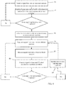
- FIG. 4 is a flow chart 70 of an embodiment of a method of operation of the collision warning system 10.
- operation of the collision warning system 10 starts when the controller 22 receives one or more signals from one or more exit sensors 52 (step 72).
- the exit sensors 52 may include a motion sensor, optical camera, seat belt sensor, ignition sensor, vehicle motion sensor, door handle sensor, etc.
- the controller 22 may then process the signals from the exit sensors 52 to determine whether an exit condition exits (e.g., if an occupant is preparing or is likely to exit the vehicle 8) (step 74).
- the controller 22 may receive signals from exit sensors 52 (e.g., vehicle motion sensor, seatbelt sensor) that indicate the vehicle 8 is no longer moving and that a seatbelt was unfastened.
- the controller 22 may receive a signal from exit sensors 52 that indicate that the vehicle 8 is now in a park gear and/or the vehicle ignition has been turned off. The controller 22 may then process these signals using a program stored in the memory 26 to determine whether this is an exit condition. If an exit condition exists, the controller 22 activates one or more collision sensors 14 (step 76). If not, the controller 22 waits for additional signals from the exit sensors 52 (step 72).
- the collision sensors 14 begin transmitting to the controller 22 and/or to the server 32 (step 78).
- the controller 22 and/or server 32 receive the signals (e.g., data) from the collision sensors 14 (step 80).
- the controller 22 and/or server 32 processes the signals using one or more programs stored in the memories 26 to determine if a hazard condition exists (e.g., whether nearby traffic is capable of contacting the vehicle occupants as they exit the vehicle 8) (step 82). If no hazard condition exists then the collision sensors 14 may continue to transmit signals from the collision sensors to the controller 22 and/or server for monitoring.
- the collision warning system 10 may continue to monitor the collision sensors 14 until all of the vehicle occupants have left the vehicle 8 (e.g., until the vehicle is locked, etc.).
- the controller 22 may continue to monitor signals from the exit sensors 52 (e.g., weight sensors, motion sensors) until all of the vehicle occupants have left.
- the controller 22 and/or server 32 detect a hazard condition then the controller 22 activates the internal and/or external warning signal system 28, 30 (step 84).
- the internal warning signal system 28 may use a variety of warning devices 50 to communicate with vehicle occupants through audio, visual, and/or vibratory signals.
- the external warning signal system 30 communicates with traffic (e.g., other vehicles, pedestrians) through warning devices 50 about a possible hazard condition as someone exits the vehicle 8.
- the warning devices 50 of the external warning signal system 28 may communicate using visual signals, auditory signals, or a combination of auditory and visual signals.
- the internal and external warning signal systems 28, 30 may remain on until the vehicle is locked, until the controller 22 determines there are no more vehicle occupants, until there is no longer a hazard condition, and/or for a specific time period, etc.
- Implementations of the embodiments may be made in hardware, firmware, software, or various combinations thereof.
- the embodiments may also be implemented as instructions stored on a machine-readable medium, which may be read and executed using one or more processing devices.
- machine-readable media may include various mechanisms for storing and/or transmitting information in a form that can be read by a machine (e.g., a computing device).
- machine-readable storage media may include read-only memory, random access memory, magnetic disk storage media, optical storage media, flash memory devices, and other media for storing information
- machine-readable transmission media may include forms of propagated signals, including carrier waves, infrared signals, digital signals, and other media for transmitting information.
- firmware, software, routines, or instructions may be described in the above disclosure in terms of specific exemplary aspects and implementations performing certain actions, it will be apparent that such descriptions are merely for the sake of convenience and that such actions in fact result from computing devices, processing devices, processors, controllers, or other devices or machines executing the firmware, software, routines, or instructions.
Landscapes
- Engineering & Computer Science (AREA)
- Physics & Mathematics (AREA)
- Mechanical Engineering (AREA)
- General Physics & Mathematics (AREA)
- Multimedia (AREA)
- Human Computer Interaction (AREA)
- Acoustics & Sound (AREA)
- Automation & Control Theory (AREA)
- Business, Economics & Management (AREA)
- Emergency Management (AREA)
- Signal Processing (AREA)
- Theoretical Computer Science (AREA)
- Electromagnetism (AREA)
- Transportation (AREA)
- Traffic Control Systems (AREA)
- Lighting Device Outwards From Vehicle And Optical Signal (AREA)
- Emergency Alarm Devices (AREA)
Abstract
Description
- The disclosure generally relates to a collision warning system for a vehicle.
- Vehicles such as cars and trucks are used in a variety of environments. Some of these environments may include dense population centers, low visibility situations, difficult weather conditions, etc. At times, these environments may be challenging for those trying to exit a vehicle while still avoiding other vehicles and pedestrians. For example, in densely populated areas roads may offer limited space for vehicles and pedestrians to travel. Accordingly, accidents may occur when drivers and passengers attempt to exit vehicles during traffic. Traffic accidents may also occur as drivers and passengers exit vehicles in low visibility situations and bad weather.
- The embodiments discussed below include a collision warning system capable of warning vehicle occupants and nearby traffic of a possible collision situation between a vehicle occupant exiting a vehicle and nearby traffic passing by. The collision warning system enables detection of a collision condition in a variety of environments using one or more collision sensors. These environments may include dense population centers, low visibility situations, and difficult weather conditions. In some embodiments, the collisions sensors may be complimentary; thus, enabling detection of a hazard condition even when some sensor capabilities are degraded (e.g., low light, bad weather). In order to warn vehicle occupants and/or neighboring traffic of a possible hazard condition, the collision warning system may include an internal warning signal system and/or an external warning signal system. The internal and external warning signal systems include one or more warning devices capable of providing a warning signal to vehicle occupants and nearby traffic. The warning signals may be audio, visual, and/or vibratory.
-
-
FIG. 1 is a top view of an embodiment of a vehicle with a collision warning system; -
FIG. 2 is an inside view of an embodiment of a vehicle with a collision warning system; -
FIG. 3 is a rear view of an embodiment of a vehicle with a collision warning system; and -
FIG. 4 is a flow chart of an embodiment of a method illustrating operation of the collision warning system. -
FIG. 1 is a top view of an embodiment of avehicle 8 with acollision warning system 10. WhileFIG. 1 illustrates a car as thevehicle 8, thevehicle 8 may be any number of other vehicles (e.g., car, truck, train, airplane, motorcycle, etc.). - In operation, the
collision warning system 10 warns vehicle occupants of an approachinghazard 12 before and/or while the vehicle occupants exit thevehicle 8. Approachinghazards 12 may include other vehicles and/or pedestrians. In some embodiments, thecollision warning system 10 may also warn neighboring traffic (e.g., other vehicles and/or pedestrians) that someone is attempting to exit or dismount thevehicle 8, thus further reducing the risk of a traffic accident. - The
collision warning system 10 includes a variety of components that operate together in order to warn drivers and passengers of a potential hazard(s) 12 as well as neighboring pedestrians, and/or other vehicles that someone is about to or is in the process of exiting thevehicle 8. These components may include a variety ofcollision sensors 14 placed at different locations on thevehicle 8. For example, thecollision sensors 14 may couple to the front of thevehicle 8, the back of thevehicle 8, on top of thevehicle 8, sides of the vehicle 8 (e.g., doors 16), and/or theside mirrors 18, etc. In this way, thecollision warning system 10 may enable 360 degree collision warning forhazards 12 approaching thevehicle 8. However, in some embodiments thevehicle 8 may only havecollision sensors 14 that enablehazard 12 detection from one direction (e.g.,hazards 12 approaching from the rear of the vehicle 8). - The
collision sensors 14 may include optical cameras, infrared cameras, motion detectors, radar, lasers, ultrasonic sensors, and/or any other sensor(s). In some embodiments, thecollision warning system 10 may includesensor packages 20 that include one or more collision sensors 14 (e.g., optical cameras, infrared cameras, motion detectors, radar, lasers, ultrasonic sensors, etc.). By including a variety ofcollision sensors 14, thecollision warning system 10 may provide redundant detection ofhazards 12 in different environmental conditions. For example, during daylight hours the optical camera may enablehazard 12 detection, but at night or in low light conditions the optical camera may not be able to identifyhazards 12. In these situations, anothercollision sensor 14, such as an infrared camera or radar, may then providehazard 12 detection. In other words, when the capability of onecollision sensor 14 is degraded anothercollision sensor 14 may still detecthazards 12. Accordingly, thecollision warning system 10 may provide continuous or nearcontinuous hazard 12 detection in a variety of conditions such as rain, low light, snow, fog, sand/dust storms, among others. - In operation, the
collision sensors 14 transmit signals (e.g., wirelessly, through wired connections) to a controller 22 (e.g., computer). Thecontroller 22 may include one ormore processors 24 that execute instructions stored on one or more memories 26 to process the signals (e.g., data) from thecollision sensors 14. For example, thecontroller 22 may receive a signal (e.g., data) from an optical camera. Theprocessor 24 may then execute a program stored on the memory 26 that recognizes objects (e.g., cars, trucks, bicycles, pedestrians, animals, etc.) in images taken by the optical camera. If theprocessor 24 detects ahazard 12, theprocessor 24 executes instructions to activate an internalwarning signal system 28 and/or an externalwarning signal system 30. In some embodiments, thecontroller 22 may continuously receive feedback from thecollision sensor 14 enabling thecontroller 22 to track changes of thepotential hazard 12 and determine if the changes alter the hazard condition (e.g., increase the risk of collision, reduce the risk of collision, or remove the risk of collision). These changes may include changes in the speed of thehazard 12; changes in the distance between thehazard 12 and thevehicle 8; changes in the direction of travel of thehazard 12; etc. Furthermore, in some embodiments, thecontroller 22 may simultaneously receive feedback frommultiple collision sensors 14 enabling thecontroller 22 to more accurately identify ahazard 12 and determine a collision condition situation. - In some embodiments, the
collision warning system 10 may connect to aremote server 32 that processes the signals from thecollision sensors 14. Indeed, instead of including processor(s) 24 on thevehicle 8 that are capable of processing the feedback from thecollision sensors 14, aremote server 32 with one ormore processors 24 may process signals from thecollision sensors 14 using instructions (e.g., programs) stored on one or more memories 26. For example, thecollision warning system 10 may include a transmitter/receiver 38 that receives signals either directly from thecollision sensors 14 or receives the signals through thecontroller 22. The transmitter/receiver 38 then transmits the sensor signals (e.g., through cellular networks, wireless networks, etc.) to theserver 32, which then processes the signals and identifies whether a collision condition exists. If theserver 32 identifies a collision condition then theserver 32 transmits a signal to thecontroller 22 to activate the internalwarning signal system 28 and/or the externalwarning signal system 30. In some embodiments, thecontroller 22 and theserver 32 may redundantly process signals from thecollision sensors 14, or theserver 32 may only process feedback from thecollision sensor 14 if thecontroller 22 is unable to do so. -
FIG. 2 is an inside view of an embodiment of avehicle 8 with acollision warning system 10. As explained above, once a hazard condition is identified thecontroller 22 activates an internalwarning signal system 28. The internalwarning signal system 28 may include any number ofwarning devices 50 that communicate in one or more ways with the vehicle occupants (e.g., visual, audio, vibration). For example, onewarning device 50 may be a display (e.g., center console display, dashboard display, seat display, heads-up display) within thevehicle 8 that provides a warning message. For example, the message may be a written message that flashes, scrolls, etc. on the display. In some embodiments, the message may be a picture that illustrates thevehicle 8 and thepotential hazard 12 with a symbol (e.g., dot, vehicle symbol, pedestrian symbol). The display may also illustrate the location of thepotential hazard 12 with respect to thevehicle 8. Moreover, in some embodiments, thecontroller 22 may be able to identify the type ofhazard 12 and then display the specific type of hazard 12 (e.g., pedestrian, vehicle, animal) on the display, thus providing the vehicle occupants with more situational awareness. - In some embodiments, the internal
warning signal system 28 may include one ormore warning devices 50 that provide an audio warning signal. For example, one ormore warning devices 50 may be audio speakers (e.g., display speakers, vehicle speakers, etc.). These audio speakers may provide a brief audio message that warns the vehicle occupants of thepotential hazards 12 outside of thevehicle 8. The audio message may be a generic warning or a specific warning that gives additional details about the type of hazard 12 (e.g., pedestrian, vehicle, animal, location, etc.). - The internal
warning signal system 28 may also include warning device(s) 50 that are lights. For example, the warning device(s) 50 may be cabin lights, reading lights, lights in the rear view mirror, lights in the side mirrors, lights on doors, lights on the car frame, or any combination thereof. These lights may flash, remain completely on, change colors, etc. For example, if thehazard 12 is avehicle 8, thecontroller 22 may rapidly flash the lights, while slowly flashing the lights if thehazard 12 is a pedestrian. In some embodiments, thecontroller 22 may increase light intensity, increase flashing, and/or change colors, etc. as thehazard 12 approaches, maintains speed, increases in speed, etc. For example, if thehazard 12 is outside of a threshold distance green lights may slowly flash to advise the vehicle occupant that ahazard 12 is approaching, but is still far enough away that the vehicle occupant may exit the vehicle while avoiding a collision. If thehazard 12 is closer, increases speed, etc. the lights may change from green to yellow flashing lights. If thehazard 12 is close and a collision is imminent or highly likely, the lights may change from yellow to red to indicate that the vehicle occupant should remain in the car until thehazard 12 has passed. Likewise, if the hazard condition changes (e.g., thehazard 12 reduces speed, changes direction, etc.) the lights may decrease in intensity, decrease rate of flashing, and/or change colors, etc. In some embodiments, thecontroller 22 may activate lights in specific locations in thevehicle 8 depending on the location of thehazard 12 and/or the location where the vehicle occupant will exit thevehicle 8. For example, if thehazard 12 is on a specific side of avehicle 8, lights may be activated only on the side of thevehicle 8 where thehazard 12 may cause a collision. - In order to assist handicapped individuals, the internal
warning signal system 28 may include one or more warning device(s) 50 capable of warning a handicapped individual. As explained above, the internalwarning signal system 28 may include visual and/oraudio warning devices 50. However, audio and visual warnings may be ineffective for people that are visually and/or hearing impaired. Therefore, by includingvibratory warning devices 50, the internalwarning signal system 28 is able to warn/caution handicapped individuals ofpotential hazards 12 when exiting avehicle 8. Thevibrator warning devices 50 may be placed at various locations in thevehicle 8. For example,vibrator warning devices 50 may be placed on the floor of thevehicle 8, enabling the occupant to feel the vibration through their feet. Thevibrator warning devices 50 may also be placed in the seats, armrests, backrests, door handles, etc. In some embodiments, thecontroller 22 may change how thevibration warning device 50 operates in response to the hazard condition. For example, if ahazard 12 is outside a threshold distance, thevibration warning device 50 may periodically turn on and off to indicate that there is ahazard 12, but that thehazard 12 is outside a threshold distance from thevehicle 8. If thehazard 12 is within a threshold distance, thevibration warning device 50 may activate and remain on, increase intensity, vibrate rapidly, etc. until the hazard condition has passed. - While the above examples of
warning devices 50 have been discussed individually some embodiments of the internalwarning signal system 28 may combine all or some of the different types ofwarning devices 50 together. For example, the internalwarning signal system 28 may combine warningdevices 50 that provide a visual message (e.g., display and/or lights) with awarning device 50 that provides an audio message. In some embodiments, the internalwarning signal system 28 may warn vehicle occupants throughwarning devices 50 that provide vibratory, visual, and auditory signals. - In operation, the internal
warning signal system 28 may be triggered through feedback fromexit sensors 52 and/or the location of thehazard 12. In order to determine where the vehicle occupant will exit the vehicle, thecontroller 22 may use one or more exit sensors 52 (e.g., a vehicle occupant sensor). Theexit sensors 52 may include motion sensors, optical cameras, seat belt sensors, an ignition sensor, a vehicle motion sensor, weight sensors, a gear sensor, door handle sensors, etc. In some embodiments, thecontroller 22 may use feedback from theexit sensors 52 andcollision sensors 14, in order to warn all vehicle occupants or tailor the warning signals (e.g., to a subset of the vehicle occupants). For example, thecontroller 22 may receive signals indicating the location of the vehicle occupant that is about to exit the vehicle 8 (e.g., front seat, back seat, driver's seat, etc.). In response, thecontroller 22 may not activate awarning device 50 if thehazard 12 is approaching a right side of thevehicle 8, and the vehicle occupant is exiting the left side of thevehicle 8. However, if there is a vehicle occupant exiting on the right side of thevehicle 8 and the hazard condition is on the right side then thecontroller 22 may activatewarning devices 50 located on the right side of thevehicle 8 or throughout thevehicle 8. -
FIG. 3 is a rear view of an embodiment of avehicle 8 with acollision warning system 10. As mentioned above, thecollision warning system 10 may also warn nearby traffic about a vehicle occupant that is about to or is in the process of exiting thevehicle 8 using the externalwarning signal system 30. In other words, thecollision warning system 10 is capable of warning vehicle occupants of a hazard condition as well as those outside of thevehicle 8. Thecollision warning system 10 may do this throughwarning devices 50 that are either visual, auditory, or through a combination of both visual and auditory signals. As illustrated, an externalwarning signal system 30 includeswarning devices 50. - The
warning devices 50 may be lights (e.g., taillights, turn signal lights, headlights, and/or special dedicated lights used by the collision warning system 10). These lights may automatically activate when a vehicle occupant triggers one or more exit sensor 52 (e.g., releases a seatbelt, grabs a door handle, stops the car, turns the ignition off, pushes a button, or a combination thereof). In some embodiments, the lights may only turn on when a hazard condition has been identified. - Once the lights are active, the
controller 22 may change/adjust the lights in response to changing conditions around the vehicle, the lights may flash, change color, change intensity, etc. For example, thecontroller 22 may increase light intensity, increase flashing, and/or change colors as thehazard 12 approaches, maintains speed, increases in speed, etc. For example, if thehazard 12 is outside of a threshold range then lights (e.g., yellow lights) may slowly flash to advise the oncoming traffic about a hazard condition. As thehazard 12 approaches, increases speed, comes within a threshold range of thevehicle 8, etc., the lights may change from yellow to red, increase intensity, increase in flash frequency, or a combination thereof. In some embodiments, thecontroller 22 may activate lights at specific locations on thevehicle 8 depending on the location of thehazard 12 and whether a vehicle occupant will exit thevehicle 8 into the path of or near thehazard 12. For example, if thehazard 12 is on a specific side of avehicle 8, lights may be activated only on the side of thevehicle 8 where thehazard 12 may cause a collision. In some embodiments, warningdevices 50 that are part of the internalwarning signal system 28 may be part of or assist the externalwarning signal system 30. As explained above, the internalwarning signal system 28 may include lights that couple to thedoor 16. These lights may remain active when thedoor 16 opens to provide additional warning to neighboring traffic. In some embodiments, the lights on thedoor 16 may turn on, change colors, change intensity, start flashing etc. when thecontroller 22 senses that the door is open and traffic is now able to see the lights. - The
warning device 50 of the externalwarning signal system 30 may also include one or more displays (e.g., heads-up display, monitors, etc.) as the warning device(s) 50. The display may be within thevehicle 8 or coupled to the exterior of thevehicle 8. In operation, the display may provide a written message such as "caution" or "warning," which flashes, scrolls, etc. across the display. In some embodiments, the message may be a symbol such as an arrow, a stop sign, an image of a person exiting a vehicle, etc. In some embodiments, the display may combine a written message with a symbol/picture. For example, the display may alternatingly present the written message and symbol/picture; simultaneously present the written message and symbol/picture; etc. enabling neighboring traffic to more clearly understand the possible hazard condition. - The external
warning signal system 28 may also include audio speakers as thewarning device 50. In operation, the audio speakers may provide a brief audio message that warns traffic near thevehicle 8 that someone is attempting to exit thevehicle 8. The audio message may be a warning noise (e.g., beeping, honking), a recorded message (e.g., a message that repeats "caution," "warning"), or a combination thereof. In some embodiments, the audio speakers used by the externalwarning signal system 28 may couple to thedoors 16 and are activated when thedoors 16 open. -
FIG. 4 is a flow chart 70 of an embodiment of a method of operation of thecollision warning system 10. In some embodiments, operation of thecollision warning system 10 starts when thecontroller 22 receives one or more signals from one or more exit sensors 52 (step 72). Theexit sensors 52 may include a motion sensor, optical camera, seat belt sensor, ignition sensor, vehicle motion sensor, door handle sensor, etc. Thecontroller 22 may then process the signals from theexit sensors 52 to determine whether an exit condition exits (e.g., if an occupant is preparing or is likely to exit the vehicle 8) (step 74). For example, thecontroller 22 may receive signals from exit sensors 52 (e.g., vehicle motion sensor, seatbelt sensor) that indicate thevehicle 8 is no longer moving and that a seatbelt was unfastened. In some embodiments, thecontroller 22 may receive a signal fromexit sensors 52 that indicate that thevehicle 8 is now in a park gear and/or the vehicle ignition has been turned off. Thecontroller 22 may then process these signals using a program stored in the memory 26 to determine whether this is an exit condition. If an exit condition exists, thecontroller 22 activates one or more collision sensors 14 (step 76). If not, thecontroller 22 waits for additional signals from the exit sensors 52 (step 72). - Once the
collision sensors 14 are active, thecollision sensors 14 begin transmitting to thecontroller 22 and/or to the server 32 (step 78). Thecontroller 22 and/orserver 32 receive the signals (e.g., data) from the collision sensors 14 (step 80). After receiving the signals, thecontroller 22 and/orserver 32 processes the signals using one or more programs stored in the memories 26 to determine if a hazard condition exists (e.g., whether nearby traffic is capable of contacting the vehicle occupants as they exit the vehicle 8) (step 82). If no hazard condition exists then thecollision sensors 14 may continue to transmit signals from the collision sensors to thecontroller 22 and/or server for monitoring. In some embodiments, thecollision warning system 10 may continue to monitor thecollision sensors 14 until all of the vehicle occupants have left the vehicle 8 (e.g., until the vehicle is locked, etc.). For example, thecontroller 22 may continue to monitor signals from the exit sensors 52 (e.g., weight sensors, motion sensors) until all of the vehicle occupants have left. - If the
controller 22 and/orserver 32 detect a hazard condition then thecontroller 22 activates the internal and/or externalwarning signal system 28, 30 (step 84). As explained above, the internalwarning signal system 28 may use a variety ofwarning devices 50 to communicate with vehicle occupants through audio, visual, and/or vibratory signals. Likewise, the externalwarning signal system 30 communicates with traffic (e.g., other vehicles, pedestrians) throughwarning devices 50 about a possible hazard condition as someone exits thevehicle 8. As explained above, thewarning devices 50 of the externalwarning signal system 28 may communicate using visual signals, auditory signals, or a combination of auditory and visual signals. Once activated, the internal and externalwarning signal systems controller 22 determines there are no more vehicle occupants, until there is no longer a hazard condition, and/or for a specific time period, etc. - Implementations of the embodiments may be made in hardware, firmware, software, or various combinations thereof. The embodiments may also be implemented as instructions stored on a machine-readable medium, which may be read and executed using one or more processing devices. In one implementation, machine-readable media may include various mechanisms for storing and/or transmitting information in a form that can be read by a machine (e.g., a computing device). For example, machine-readable storage media may include read-only memory, random access memory, magnetic disk storage media, optical storage media, flash memory devices, and other media for storing information, and machine-readable transmission media may include forms of propagated signals, including carrier waves, infrared signals, digital signals, and other media for transmitting information. While firmware, software, routines, or instructions may be described in the above disclosure in terms of specific exemplary aspects and implementations performing certain actions, it will be apparent that such descriptions are merely for the sake of convenience and that such actions in fact result from computing devices, processing devices, processors, controllers, or other devices or machines executing the firmware, software, routines, or instructions.
- Furthermore, aspects and implementations may be described in the above disclosure as including particular features, structures, or characteristics, but it will be apparent that every aspect or implementation may or may not necessarily include the particular features, structures, or characteristics. Further, where particular features, structures, or characteristics have been described in connection with a specific aspect or implementation, it will be understood that such features, structures, or characteristics may be included with other aspects or implementations, whether or not explicitly described. Thus, various changes and modifications may be made to the preceding disclosure without departing from the scope or spirit of the invention, and the specification and drawings should therefore be regarded as exemplary only, with the scope of the invention determined solely by the appended claims.
Claims (15)
- A collision warning system, comprising:- a first sensor coupled to a vehicle and configured to generate a first signal indicating an exit condition;- a second sensor coupled to the vehicle and configured to generate a second signal indicating neighboring traffic; and- an external warning signal system coupled to the vehicle and configured to emit an audio and/or visual external warning signal in response to the first signal and the second signal to warn the neighboring traffic about a collision condition.
- The system of claim 1,
wherein the external warning signal system comprises a warning device coupled to the vehicle and configured to emit the audio and/or visual external warning signal. - The system of claim 2,
wherein the external warning signal system comprises a controller configured to:- receive the first signal from the first sensor;- receive the second signal from the second sensor; and- generate a control signal to control the warning device to emit the audio and/or visual external warning signal to warn about the collision condition in response to receiving the first and second signals. - The system of claim 2 or 3,
wherein the warning device is a display that displays at least one of a written message and a visual image that warns the neighboring traffic of the collision condition; and/or
wherein the warning device is an audio speaker. - The system of one of claims 1 to 4,
wherein the first sensor is at least one of a seatbelt sensor, motion sensor, optical camera, ignition sensor, gear sensor, and door handle sensor; and/or
wherein the second sensor is at least one of an optical camera, infrared camera, motion detector, radar, laser, and ultrasonic sensor. - The system of one of claims 1 to 5,
wherein the visual external warning signal is a light beam. - A method for warning traffic of a collision condition around a vehicle, comprising:- receiving a first signal from a first sensor coupled to the vehicle, the first signal indicating an exit condition;- receiving a second signal from a second sensor coupled to the vehicle, the second signal indicating neighboring traffic; and- detecting a collision condition in response to the first and second signals.
- The method of claim 7,
comprising generating a control signal to cause a warning device coupled to the vehicle to emit an audio and/or visual external warning signal in response to the detected collision condition. - The method of claim 7 or 8,
wherein the first sensor is at least one of a seatbelt sensor, motion sensor, optical camera, ignition sensor, gear sensor, and door handle sensor;
and/or
wherein the second sensor is at least one of an optical camera, infrared camera, motion detector, radar, laser, and ultrasonic sensor. - The method of one of claims 7 to 9,
wherein the visual external warning signal is a light beam. - The method of claim 10,
further comprising changing at least one of a color, an intensity, and a flash frequency of the light beam in response to a change in the collision condition. - The method of one of claims 7 to 11 in combination with claim 8,
wherein the warning device is a display. - The method of claim 12,
further comprising displaying with the display at least one of a written message and a visual image as the visual external warning signal. - The method of one of claims 7 to 13 in combination with claim 8,
wherein the warning device is an audio speaker. - The method of one of claims 7 to 14,
further comprising activating a visual external warning signal on a side of
the vehicle where a passenger will exit.
Applications Claiming Priority (2)
| Application Number | Priority Date | Filing Date | Title |
|---|---|---|---|
| US14/983,617 US9511730B1 (en) | 2015-12-30 | 2015-12-30 | Collision warning system |
| US15/291,826 US10026319B2 (en) | 2015-12-30 | 2016-10-12 | Collision warning system |
Publications (2)
| Publication Number | Publication Date |
|---|---|
| EP3187372A2 true EP3187372A2 (en) | 2017-07-05 |
| EP3187372A3 EP3187372A3 (en) | 2017-08-02 |
Family
ID=57681384
Family Applications (1)
| Application Number | Title | Priority Date | Filing Date |
|---|---|---|---|
| EP16206363.0A Withdrawn EP3187372A3 (en) | 2015-12-30 | 2016-12-22 | Collision warning system and method |
Country Status (3)
| Country | Link |
|---|---|
| US (1) | US10026319B2 (en) |
| EP (1) | EP3187372A3 (en) |
| CN (4) | CN106985738A (en) |
Cited By (8)
| Publication number | Priority date | Publication date | Assignee | Title |
|---|---|---|---|---|
| FR3078035A1 (en) * | 2018-06-28 | 2019-08-23 | Continental Automotive France | VEHICLE ENVIRONMENT DETECTION SYSTEM |
| WO2019203916A1 (en) * | 2018-04-19 | 2019-10-24 | Byton North America Corporation | Door opening clearance detection |
| EP4086116A1 (en) * | 2021-05-07 | 2022-11-09 | Guangzhou Xiaopeng Motors Technology Co., Ltd. | Vehicle door-opening anti-collision method and apparatus, vehicle, and storage medium |
| US11963065B2 (en) * | 2018-06-29 | 2024-04-16 | Geotab Inc. | Characterizing a vehicle collision |
| US12094260B2 (en) | 2012-06-04 | 2024-09-17 | Geotab Inc. | VIN based accelerometer threshold |
| US12397785B1 (en) | 2024-02-09 | 2025-08-26 | Geotab Inc. | Systems and methods for detecting vehicle collisions |
| EP4606645A1 (en) * | 2024-02-23 | 2025-08-27 | Toyota Jidosha Kabushiki Kaisha | Method and apparatus for informing a vulnerable road user of a vehicle's state |
| US12444306B2 (en) | 2021-02-03 | 2025-10-14 | Geotab Inc. | Methods for characterizing a vehicle collision |
Families Citing this family (25)
| Publication number | Priority date | Publication date | Assignee | Title |
|---|---|---|---|---|
| CN107111949B (en) * | 2014-12-26 | 2020-04-10 | 横滨橡胶株式会社 | Anti-collision system and anti-collision method |
| US9725038B2 (en) | 2015-11-24 | 2017-08-08 | Thunder Power New Energy Vehicle Development Company Limited | Collision warning system |
| US10059261B2 (en) | 2015-11-24 | 2018-08-28 | Thunder Power New Energy Vehicle Development Company Limited | Collision warning system |
| US10026319B2 (en) * | 2015-12-30 | 2018-07-17 | Thunder Power New Energy Vehicle Development Limited | Collision warning system |
| US10059255B1 (en) * | 2017-06-16 | 2018-08-28 | Hyundai Motor Company | Systems and methods for vehicle recognition using mobile device |
| US10867205B2 (en) * | 2017-07-18 | 2020-12-15 | Lenovo (Singapore) Pte. Ltd. | Indication of characteristic based on condition |
| CN111094113B (en) * | 2018-06-07 | 2021-01-05 | 日本精工株式会社 | Electric power steering apparatus |
| EP3594035B1 (en) * | 2018-07-10 | 2021-01-13 | Ningbo Geely Automobile Research & Development Co., Ltd. | A vehicle comprising a door opening warning system |
| US11135917B2 (en) | 2018-09-05 | 2021-10-05 | Denso International America, Inc. | Forward collision avoidance display |
| CN110880250B (en) * | 2018-09-05 | 2022-05-03 | 奥迪股份公司 | Danger early warning system and method |
| US10347132B1 (en) * | 2018-10-30 | 2019-07-09 | GM Global Technology Operations LLC | Adjacent pedestrian collision mitigation |
| EP3666594B1 (en) * | 2018-12-12 | 2022-08-10 | Ningbo Geely Automobile Research & Development Co. Ltd. | System and method for warning a driver of a vehicle of an object in a proximity of the vehicle |
| CN109624840A (en) * | 2018-12-29 | 2019-04-16 | 重庆金康新能源汽车设计院有限公司 | Vehicle drive method for early warning, image process controller, system and vehicle |
| US10882538B1 (en) * | 2019-07-31 | 2021-01-05 | Karma Automotive Llc | System and method for a combined visual and audible spatial warning system |
| DE102020104535A1 (en) * | 2020-02-20 | 2021-08-26 | Bayerische Motoren Werke Aktiengesellschaft | Method for supporting an occupant when getting out of a vehicle, taking into account follow-up objects, computing device and driver assistance system |
| US11548442B2 (en) | 2020-05-12 | 2023-01-10 | GM Cruise Holdings LLC. | Passenger safeguards for autonomous vehicles |
| KR20220036454A (en) * | 2020-09-15 | 2022-03-23 | 현대자동차주식회사 | Safety warning apparatus for passengers getting off and method thereof |
| US11724643B2 (en) * | 2021-01-20 | 2023-08-15 | Ford Global Technologies, Llc | Vehicle alarm |
| KR20220112335A (en) * | 2021-02-03 | 2022-08-11 | 현대모비스 주식회사 | Its control method and Exit Warning system |
| JP7524820B2 (en) * | 2021-04-12 | 2024-07-30 | トヨタ自動車株式会社 | Exit assistance device |
| KR102592665B1 (en) * | 2021-07-01 | 2023-10-24 | 현대모비스 주식회사 | Apparatus for collision waring and vehicle including the same |
| CN113581063A (en) * | 2021-08-12 | 2021-11-02 | 江苏爱玛车业科技有限公司 | Night intelligent recognition warning system and vehicle |
| EP4350643A1 (en) * | 2022-10-05 | 2024-04-10 | Aptiv Technologies AG | Vehicle exit assistance |
| CN117373286A (en) * | 2023-10-25 | 2024-01-09 | 广西信路威科技发展有限公司 | A low-power meeting vehicle warning and reminder device and method |
| CN118596988A (en) * | 2024-07-23 | 2024-09-06 | 中国第一汽车股份有限公司 | In-vehicle reading light control method, device and vehicle |
Family Cites Families (39)
| Publication number | Priority date | Publication date | Assignee | Title |
|---|---|---|---|---|
| JPS5790447A (en) | 1980-11-21 | 1982-06-05 | Nissan Motor Co Ltd | Alarm unit of automatic speed change gear |
| US4965546A (en) | 1988-07-12 | 1990-10-23 | Chang Jih Cheng | Warning device to alert passers-by before opening an automobile door |
| US5015991A (en) | 1990-03-27 | 1991-05-14 | Barr William A | Alarm system for vehicle automatic transmission |
| US5467071A (en) | 1993-12-15 | 1995-11-14 | Gerald J. Churchill | Audiovisual safety warning kit |
| WO1997014584A1 (en) | 1995-10-17 | 1997-04-24 | Calsonic Corporation | Warning device for distance between cars |
| US5914651A (en) | 1997-12-04 | 1999-06-22 | Smalls; Bryan H. | Vehicle safety emergency flasher system |
| US5969603A (en) | 1998-05-07 | 1999-10-19 | Wang; Chun-Chung | Door opening warning system device for cars |
| US6922147B1 (en) | 2001-07-12 | 2005-07-26 | Ann S. Viksnins | Warning system sensing child left behind in infant seat in vehicle |
| US6535137B1 (en) | 2001-09-24 | 2003-03-18 | Janet Lee Ryan | Child seat alarm |
| US20030122662A1 (en) | 2002-01-02 | 2003-07-03 | Quinonez David R. | Baby car seat alert and range alarm |
| CH695857A5 (en) | 2002-04-08 | 2006-09-29 | Claudio Cipriani | Door opening warning device for e.g. car, has switching unit connected with ignition lock and door opening lever such that warning lights are switched on by delivering of optical warning signal on side of vehicle door during door opening |
| US7012533B2 (en) | 2003-09-11 | 2006-03-14 | Younse Jack M | Occupant detection and notification system for use with a child car seat |
| DE102007023929A1 (en) | 2007-05-23 | 2008-11-27 | Lucas Automotive Gmbh | Technology for starting a motor vehicle on a sloping route |
| DE102007036079A1 (en) * | 2007-08-01 | 2009-02-05 | GM Global Technology Operations, Inc., Detroit | Method for operating a motor vehicle and control device |
| US20090033474A1 (en) | 2007-08-02 | 2009-02-05 | I-Shou University | Car door opening early-warning system |
| AR065923A1 (en) | 2007-08-09 | 2009-07-08 | Barros Alejandro Rodriguez | ANTICIPATED NOTICE SYSTEM OF OPENING A DOOR OF MOTOR VEHICLE |
| JP5329194B2 (en) * | 2008-12-09 | 2013-10-30 | タカタ株式会社 | Collision determination system, occupant restraint system, vehicle |
| CN201402328Y (en) | 2009-03-30 | 2010-02-10 | 德尔福技术有限公司 | Safety detection device for distance from vehicle |
| CN201604958U (en) | 2009-12-17 | 2010-10-13 | 徐正龙 | Elastic garbage can |
| US8620549B2 (en) | 2010-09-14 | 2013-12-31 | GM Global Technology Operations LLC | Vehicle safety systems and methods |
| US10223915B2 (en) | 2011-01-29 | 2019-03-05 | Russell Haines | System that warns in advance of occupants exiting or entering a parked vehicle |
| DE102011076340A1 (en) * | 2011-05-24 | 2012-11-29 | Robert Bosch Gmbh | Method and device for warning road users |
| DE102012005075A1 (en) * | 2012-03-13 | 2013-09-19 | Gm Global Technology Operations, Llc | A method of warning against a possible collision of an object with a vehicle door of a stationary motor vehicle |
| US8493198B1 (en) | 2012-07-11 | 2013-07-23 | Google Inc. | Vehicle and mobile device traffic hazard warning techniques |
| US20140098230A1 (en) | 2012-10-08 | 2014-04-10 | Magna Mirrors Of America, Inc. | Blind zone detection and alert system for vehicle |
| DE102013001276A1 (en) * | 2013-01-25 | 2014-07-31 | GM Global Technology Operations LLC (n. d. Gesetzen des Staates Delaware) | Method for controlling bending light in motor car, involves intermittently activating bending lights on sides by road user, and turning on and off bending lights with frequency that is adapted to predefined parameter |
| JP6173746B2 (en) | 2013-04-04 | 2017-08-02 | 矢崎総業株式会社 | Vehicle alarm device |
| CN104149729B (en) * | 2013-05-13 | 2017-07-21 | 上海汽车集团股份有限公司 | The method and system of identification traveling vehicle periphery barrier |
| CN203402060U (en) | 2013-07-16 | 2014-01-22 | 北京汽车股份有限公司 | Driving safety auxiliary system and automobile |
| CN104512365A (en) | 2013-10-07 | 2015-04-15 | 青岛联合创新技术服务平台有限公司 | Vehicle collision avoidance control system |
| CN104590155B (en) * | 2013-11-01 | 2017-10-31 | 大陆汽车投资(上海)有限公司 | Device for preventing car door from colliding with object when opened |
| CN103587488B (en) * | 2013-11-19 | 2017-07-07 | 浙江吉利汽车研究院有限公司 | Avoid the safety device of car door and pedestrian collision |
| US9688199B2 (en) * | 2014-03-04 | 2017-06-27 | Magna Electronics Inc. | Vehicle alert system utilizing communication system |
| US20140297173A1 (en) | 2014-06-18 | 2014-10-02 | Ming-Chih Li | System for alerting automobile driver when opening door |
| CN105059216A (en) * | 2015-08-17 | 2015-11-18 | 南京航空航天大学 | Automobile door opening anti-collision system |
| US9725038B2 (en) | 2015-11-24 | 2017-08-08 | Thunder Power New Energy Vehicle Development Company Limited | Collision warning system |
| US10059261B2 (en) * | 2015-11-24 | 2018-08-28 | Thunder Power New Energy Vehicle Development Company Limited | Collision warning system |
| US10026319B2 (en) * | 2015-12-30 | 2018-07-17 | Thunder Power New Energy Vehicle Development Limited | Collision warning system |
| US9511730B1 (en) | 2015-12-30 | 2016-12-06 | Thunder Power Hong Kong Ltd. | Collision warning system |
-
2016
- 2016-10-12 US US15/291,826 patent/US10026319B2/en active Active
- 2016-12-20 CN CN201611180562.4A patent/CN106985738A/en active Pending
- 2016-12-20 CN CN201621397756.5U patent/CN207466478U/en not_active Expired - Fee Related
- 2016-12-20 CN CN201621397870.8U patent/CN207257509U/en not_active Expired - Fee Related
- 2016-12-20 CN CN201611180600.6A patent/CN106965747A/en active Pending
- 2016-12-22 EP EP16206363.0A patent/EP3187372A3/en not_active Withdrawn
Non-Patent Citations (1)
| Title |
|---|
| None |
Cited By (9)
| Publication number | Priority date | Publication date | Assignee | Title |
|---|---|---|---|---|
| US12094260B2 (en) | 2012-06-04 | 2024-09-17 | Geotab Inc. | VIN based accelerometer threshold |
| WO2019203916A1 (en) * | 2018-04-19 | 2019-10-24 | Byton North America Corporation | Door opening clearance detection |
| FR3078035A1 (en) * | 2018-06-28 | 2019-08-23 | Continental Automotive France | VEHICLE ENVIRONMENT DETECTION SYSTEM |
| US11963065B2 (en) * | 2018-06-29 | 2024-04-16 | Geotab Inc. | Characterizing a vehicle collision |
| US12375876B2 (en) | 2018-06-29 | 2025-07-29 | Geotab Inc. | Characterizing a vehicle collision |
| US12444306B2 (en) | 2021-02-03 | 2025-10-14 | Geotab Inc. | Methods for characterizing a vehicle collision |
| EP4086116A1 (en) * | 2021-05-07 | 2022-11-09 | Guangzhou Xiaopeng Motors Technology Co., Ltd. | Vehicle door-opening anti-collision method and apparatus, vehicle, and storage medium |
| US12397785B1 (en) | 2024-02-09 | 2025-08-26 | Geotab Inc. | Systems and methods for detecting vehicle collisions |
| EP4606645A1 (en) * | 2024-02-23 | 2025-08-27 | Toyota Jidosha Kabushiki Kaisha | Method and apparatus for informing a vulnerable road user of a vehicle's state |
Also Published As
| Publication number | Publication date |
|---|---|
| CN207466478U (en) | 2018-06-08 |
| US20170193824A1 (en) | 2017-07-06 |
| CN106985738A (en) | 2017-07-28 |
| EP3187372A3 (en) | 2017-08-02 |
| US10026319B2 (en) | 2018-07-17 |
| CN207257509U (en) | 2018-04-20 |
| CN106965747A (en) | 2017-07-21 |
Similar Documents
| Publication | Publication Date | Title |
|---|---|---|
| US10026319B2 (en) | Collision warning system | |
| US9511730B1 (en) | Collision warning system | |
| US10059261B2 (en) | Collision warning system | |
| US10343601B2 (en) | Collision warning system | |
| US10332401B2 (en) | Running vehicle alerting system and method | |
| JP7471021B2 (en) | Systems and programs | |
| US9352683B2 (en) | Traffic density sensitivity selector | |
| US10081299B2 (en) | Front end sensor for pedestrians | |
| US20180144636A1 (en) | Distracted driver detection, classification, warning, avoidance system | |
| EP3849865A1 (en) | Inward/outward vehicle monitoring for remote reporting and in-cab warning enhancements | |
| JP7760190B2 (en) | Systems and programs | |
| JP4517393B2 (en) | Driving assistance device | |
| US20140078291A1 (en) | Driver Assisting System and Method for a Motor Vehicle | |
| WO2019108108A1 (en) | Method and control arrangement for maintaining a vehicle formation | |
| JP7652329B2 (en) | Vehicle control device and vehicle control method | |
| HK1240548A1 (en) | Collision warning system and method | |
| HK1240547A1 (en) | Collision warning system and method | |
| HK1238202A1 (en) | Collision warning system | |
| HK1241327A1 (en) | Collision warning system for vehicle | |
| HK1241815A1 (en) | Vehicle with collision warning system | |
| HK1229299A1 (en) | Collision warning system | |
| HK1229299B (en) | Collision warning system | |
| KR20230168060A (en) | Method and apparatus for supporting safety exit of a vehicle | |
| KR20230143245A (en) | Right turn safety system and method for vehicle |
Legal Events
| Date | Code | Title | Description |
|---|---|---|---|
| PUAI | Public reference made under article 153(3) epc to a published international application that has entered the european phase |
Free format text: ORIGINAL CODE: 0009012 |
|
| PUAL | Search report despatched |
Free format text: ORIGINAL CODE: 0009013 |
|
| AK | Designated contracting states |
Kind code of ref document: A2 Designated state(s): AL AT BE BG CH CY CZ DE DK EE ES FI FR GB GR HR HU IE IS IT LI LT LU LV MC MK MT NL NO PL PT RO RS SE SI SK SM TR |
|
| AX | Request for extension of the european patent |
Extension state: BA ME |
|
| AK | Designated contracting states |
Kind code of ref document: A3 Designated state(s): AL AT BE BG CH CY CZ DE DK EE ES FI FR GB GR HR HU IE IS IT LI LT LU LV MC MK MT NL NO PL PT RO RS SE SI SK SM TR |
|
| AX | Request for extension of the european patent |
Extension state: BA ME |
|
| RIC1 | Information provided on ipc code assigned before grant |
Ipc: G08G 1/0962 20060101ALI20170627BHEP Ipc: B60Q 3/80 20170101ALN20170627BHEP Ipc: B60Q 1/50 20060101AFI20170627BHEP Ipc: G08B 21/24 20060101ALI20170627BHEP Ipc: B60Q 5/00 20060101ALI20170627BHEP Ipc: G08G 1/16 20060101ALI20170627BHEP Ipc: B60Q 9/00 20060101ALI20170627BHEP |
|
| RIC1 | Information provided on ipc code assigned before grant |
Ipc: B60Q 1/50 20060101AFI20170717BHEP Ipc: G08G 1/0962 20060101ALI20170717BHEP Ipc: G08B 21/24 20060101ALI20170717BHEP Ipc: B60Q 5/00 20060101ALI20170717BHEP Ipc: B60Q 9/00 20060101ALI20170717BHEP Ipc: G08G 1/16 20060101ALI20170717BHEP Ipc: B60Q 3/80 20170101ALN20170717BHEP |
|
| REG | Reference to a national code |
Ref country code: HK Ref legal event code: DE Ref document number: 1240548 Country of ref document: HK |
|
| STAA | Information on the status of an ep patent application or granted ep patent |
Free format text: STATUS: THE APPLICATION IS DEEMED TO BE WITHDRAWN |
|
| 18D | Application deemed to be withdrawn |
Effective date: 20180203 |
|
| REG | Reference to a national code |
Ref country code: HK Ref legal event code: WD Ref document number: 1240548 Country of ref document: HK |