EP3187258B1 - Improvement in or relating to reactors - Google Patents
Improvement in or relating to reactors Download PDFInfo
- Publication number
- EP3187258B1 EP3187258B1 EP16207547.7A EP16207547A EP3187258B1 EP 3187258 B1 EP3187258 B1 EP 3187258B1 EP 16207547 A EP16207547 A EP 16207547A EP 3187258 B1 EP3187258 B1 EP 3187258B1
- Authority
- EP
- European Patent Office
- Prior art keywords
- agitator
- reactor
- vessel
- flow
- heat transfer
- Prior art date
- Legal status (The legal status is an assumption and is not a legal conclusion. Google has not performed a legal analysis and makes no representation as to the accuracy of the status listed.)
- Active
Links
Images


Classifications
-
- B—PERFORMING OPERATIONS; TRANSPORTING
- B01—PHYSICAL OR CHEMICAL PROCESSES OR APPARATUS IN GENERAL
- B01J—CHEMICAL OR PHYSICAL PROCESSES, e.g. CATALYSIS OR COLLOID CHEMISTRY; THEIR RELEVANT APPARATUS
- B01J19/00—Chemical, physical or physico-chemical processes in general; Their relevant apparatus
- B01J19/18—Stationary reactors having moving elements inside
- B01J19/1812—Tubular reactors
-
- B—PERFORMING OPERATIONS; TRANSPORTING
- B01—PHYSICAL OR CHEMICAL PROCESSES OR APPARATUS IN GENERAL
- B01F—MIXING, e.g. DISSOLVING, EMULSIFYING OR DISPERSING
- B01F27/00—Mixers with rotary stirring devices in fixed receptacles; Kneaders
- B01F27/60—Mixers with rotary stirring devices in fixed receptacles; Kneaders with stirrers rotating about a horizontal or inclined axis
-
- B—PERFORMING OPERATIONS; TRANSPORTING
- B01—PHYSICAL OR CHEMICAL PROCESSES OR APPARATUS IN GENERAL
- B01F—MIXING, e.g. DISSOLVING, EMULSIFYING OR DISPERSING
- B01F31/00—Mixers with shaking, oscillating, or vibrating mechanisms
- B01F31/44—Mixers with shaking, oscillating, or vibrating mechanisms with stirrers performing an oscillatory, vibratory or shaking movement
- B01F31/445—Mixers with shaking, oscillating, or vibrating mechanisms with stirrers performing an oscillatory, vibratory or shaking movement performing an oscillatory movement about an axis
-
- B—PERFORMING OPERATIONS; TRANSPORTING
- B01—PHYSICAL OR CHEMICAL PROCESSES OR APPARATUS IN GENERAL
- B01J—CHEMICAL OR PHYSICAL PROCESSES, e.g. CATALYSIS OR COLLOID CHEMISTRY; THEIR RELEVANT APPARATUS
- B01J19/00—Chemical, physical or physico-chemical processes in general; Their relevant apparatus
- B01J19/0053—Details of the reactor
- B01J19/0066—Stirrers
-
- B—PERFORMING OPERATIONS; TRANSPORTING
- B01—PHYSICAL OR CHEMICAL PROCESSES OR APPARATUS IN GENERAL
- B01J—CHEMICAL OR PHYSICAL PROCESSES, e.g. CATALYSIS OR COLLOID CHEMISTRY; THEIR RELEVANT APPARATUS
- B01J2219/00—Chemical, physical or physico-chemical processes in general; Their relevant apparatus
- B01J2219/00049—Controlling or regulating processes
- B01J2219/00051—Controlling the temperature
- B01J2219/00074—Controlling the temperature by indirect heating or cooling employing heat exchange fluids
- B01J2219/00076—Controlling the temperature by indirect heating or cooling employing heat exchange fluids with heat exchange elements inside the reactor
- B01J2219/00085—Plates; Jackets; Cylinders
-
- B—PERFORMING OPERATIONS; TRANSPORTING
- B01—PHYSICAL OR CHEMICAL PROCESSES OR APPARATUS IN GENERAL
- B01J—CHEMICAL OR PHYSICAL PROCESSES, e.g. CATALYSIS OR COLLOID CHEMISTRY; THEIR RELEVANT APPARATUS
- B01J2219/00—Chemical, physical or physico-chemical processes in general; Their relevant apparatus
- B01J2219/00274—Sequential or parallel reactions; Apparatus and devices for combinatorial chemistry or for making arrays; Chemical library technology
- B01J2219/00277—Apparatus
- B01J2219/00479—Means for mixing reactants or products in the reaction vessels
- B01J2219/00481—Means for mixing reactants or products in the reaction vessels by the use of moving stirrers within the reaction vessels
Definitions
- the present invention relates to improvements in or relating to reactors and/or mixers and in particular to reactors through which process materials flow continuously.
- the invention relates to the provision of agitation within reactants as they pass along the length of a reactor.
- the reactor with which the invention is concerned may be tubular, it may be single stage or multistage and the stages may be in series or in parallel. Furthermore the reactor may be horizontal, vertical, inclined or a combination thereof.
- the process fluid flows through the reactor in a manner as close to plug flow as possible as this ensures that all the reactants are subjected to substantially the same conditions as they pass through the reactor.
- Flow in a manner that is as near to plug flow as possible is essential in good continuous flow processes to ensure a consistent residence time of material within the reactor and to reduce the variabilities in the product.
- the reactants are well mixed and are uniformly mixed in order to optimise the speed and yield of the reaction. Accordingly the ideal conditions in a continuous flow reactor are that the axial flow of the reactants is plug flow whilst the flowing plug is subjected to efficient radial mixing. Although these ideal conditions may not be attainable the present invention provides a reaction system that moves the conditions in a continuous reactor nearer to the ideal situation.
- the present invention provides what we have called the flip-flop agitator system.
- the flip-flop agitator system overcomes these shortfalls by both acting as agitator and baffle.
- the invention provides a reaction vessel through which process material can flow in a continuous manner entering through an inlet and leaving via an outlet wherein an agitator is provided inside the vessel which is capable of reciprocal movement through an arc.
- the invention further provides a process in which a process fluid flows continuously through a vessel and the agitator is rotated in one direction, is then stopped and then driven in the reverse direction.
- the rotation of the agitator in the first direction accelerates the process fluid radially within the reactor and the rotation in the second direction creates turbulence/mixing.
- the reactor is a tubular reactor as described and the agitator comprises a probe within the tubular reactor extending substantially along the length of the reactor and through holes (at least one but not limited in number) are cut into the body of the agitator. These holes permit and encourage radial flow of the process liquid through the agitator body and provide a mixing system that is much closer to plug flow conditions and is scalable from small laboratory systems to much larger industrial scales.
- the flip-flop agitator action as employed in this invention is as follows.
- mixing action performed according to the process of this invention may be any of the following combinations of movement.
- the flip-flop agitator can be effectively operated by a number of different motive forces, including, but not limited to, compressed gases (e.g. air or nitrogen), electricity and hydraulics. These are used to power actuators, including hydraulic motors, electric motors, pneumatic motors and pneumatic actuators that turn the actuator in the desired action via a shaft and coupling mechanism.
- the agitator driveshaft can be either coupled to the actuator directly through a seal or magnetically coupled.
- the size and shape of the agitator used in this invention may be chosen according to the size and shape of the reactor or the nature of the reaction or mixing process for which the reactor is to be used.
- the sizes and shapes of the agitator may be varied within a tubular reactor according to the reaction or mixing that is being performed and this can increase the flexibility and use of the invention.
- an agitator with sharp corners and also having a rectangular cross section with the surfaces changing from convex to concave in design provides particularly good mixing generating radial turbulence in the process fluid.
- good mixing is achieved if the agitator occupies from 10% to 99 %, preferably 25% to 90% of the cross sectional area of the tube within which it is used.
- free moving agitation elements can be housed within the main agitator body which in combination with through holes in the agitator serve to push and pull the process material tangentially to the axial plane of the agitator and radially to the direction of flow of the process fluid. Centrifugal and gravitational forces will drive the free moving elements.
- catalysts and other solids may be immobilised and held captive within the agitator through holes. Free moving agitation elements can again be used to assist the radial flow of the process fluid through the immobilised catalyst or solids.
- the agitator is driven by a pneumatic motor first in the clockwise direction, then stopped and driven in the counter clockwise direction (or vice versa). This action is repeated multiple times for time periods that are determined according to the nature of the process materials and the speed at which they pass through the reactor in order to give the desired mixing effect.
- a pneumatic rotary actuator which is limited in its freedom to rotate by a mechanical stop is used to drive the flip-flop agitator in the clockwise direction, then stopped and driven in the counter clockwise direction (or vice versa).
- the freedom of the actuator to freely rotate is limited by a mechanical stop. This sudden stopping of the agitator as it hits the mechanical stop creates turbulence within the process fluid, due to the inertia of the process fluid within the reactor, which was up until that instant being pushed along by the movement of the agitator.
- Pneumatic rotary actuators use pressurized gases to rotate mechanical components.
- rotary actuators include single rack-and-pinion actuators; double or four piston rack-and-pinion actuators; single rotary vane devices which are actuated directly by pressurized gas and double rotary vane devices that use two chambers of pressurized gas to produce increased torque.
- Multi-motion rotary vane actuators are also available and suited to this application.
- a double vane rotary actuator is used as this has more torque and faster acceleration from the stationary position which can be utilized to provide the agitator with higher shear mixing capabilities.
- a stepper motor is used to actuate the flip-flop agitator in the clockwise direction, then stopped and driven in the counter clockwise direction (or vice versa).
- the stepper motor does not require a mechanical stop and can be rotated without limit in either direction.
- the stepper motor When stationary the stepper motor has a high holding torque that resists the force of the inertia generated by the moving process fluid. The sudden stopping of the agitator creates turbulence within the process fluid, due to the inertia of the process fluid, which was up until that instant being pushed along by the movement of the agitator.
- a stepper motor is a type of electric motor that converts electrical pulses into discrete mechanical movements. Typically each step can produces a 1.8° rotation of the motor shaft per pulse. Higher resolution stepping can be produced however with the use of electronic motor control systems.
- the speed of the motor shafts rotation is directly related to the frequency of the input pulses and the length of rotation is directly related to the number of input pulses applied.
- a stepper motor provides a very flexible solution that allows both the agitator speed and degrees of movement before stopping and or changing direction to be varied and adjusted to suit the exact process requirements at any point of the process. Consequently in flow reactor systems that employ real time monitoring of the reaction state, adjustments to the process mixing can be made in response to process disturbances, or when changes in state are detected in the process media at a certain point in the process.
- agitator drive system employed will ultimately depend on the each particular process or unit operation. In most circumstances however a system wherein the bidirectional speed of the agitation is between 0.001 and 100 flip-flop cycles per second with the agitator travelling at speeds between 1 and 10000 rpm, will fulfil most operational needs.
- Flow reactors are traditionally operated as open loop steady state systems where the process is switched on and manually adjusted until an acceptable output is achieved. Residence times of the reactants within the reactors are usually held at an ideal constant. Whilst this technique works well at small scales, at industrial scales where plant disturbances are more prevalent and of more significance, process variabilities are often encountered.
- the reactor system can be operated as a continuous plug flow reactor that combines CSTR and tubular technology to improve heat transfer and mixing control. This can be achieved by closing the controlling loop using analytical instrumentation to monitor the system and using the analysis to cause changes in the operating conditions to achieve the desired temperature profile and energy balance along the reactor.
- analytical instrumentation to monitor the system and using the analysis to cause changes in the operating conditions to achieve the desired temperature profile and energy balance along the reactor.
- the analysis required will depend upon the nature of the reaction although analytical techniques that may be used include particle size analysis, Fourier Transform Infrared Spectroscopy, Ultra Violet Resonance Spectroscopy, Raman Spectroscopy or the measurement of heat reaction.
- the reactor may consist of multiple stages with the rate of change in heat measured at each stage; allowing for an assessment of the reaction rate and the stability of the reaction along the reactor.
- a heat transfer jacket in which internal mixing of the heat transfer fluid is provided within the heat transfer jacket in order to create turbulent flow of the heat transfer fluid.
- the turbulence in the heat transfer fluid is created by the provision of flow interrupting elements within the jacket.
- the choice of the interrupting elements may depend upon the size and shape of the reactor. For smaller scale reactors such as laboratory reactors the interrupting elements may be loose spheres which pack out the jacket and create turbulent flow conditions, as the heat transfer fluid is pumped through the jacket. Larger scale reactors with larger volume heat transfer jackets may require baffles to produce sufficient turbulence. Other interrupting elements can however be used such as other loose shapes, prefabricated baffles, flow disrupters or turbulator assemblies.
- the flow interruption elements can be any suitable size or shape. They may be baffles integral with the internal walls of the heat transfer jacket but we prefer to use loose elements within the jacket. In particular we have found that if the jacket is packed with loose elements around which the heat transfer fluid flows it is possible to achieve much more uniform control of the energy of the system and also control of the temperature of the reactants.
- the flow interruption elements have a high thermal conductivity as this can help to reduce the formation of temperature differentials within the heat transfer fluid in the jacket.
- Small metal spheres or metal baffles have been found to be particularly useful, in particular metal spheres having a copper exterior are especially useful in small reactors.
- turbulence in the heat transfer fluid may also be accomplished by reversing the direction of flow of the heat transfer fluid within the jacket or by pulsing the flow in a single direction.
- Reversing may be achieved by the provision of synchronised pumps at both ends of the heat transfer jacket.
- Pulsing may be achieved by suitable programming of the pump system that injects the fluid into the jacket. The reversal may be periodic and occasional.
- the reversal of the heat transfer fluid may momentarily reverse the direction of flow of the heat transfer fluid.
- the direction of heat transfer fluid flow remains overall in the forwards direction through the jacket, but the momentarily reversal of flow creates an oscillation in the flow and turbulence/mixing is subsequently created as the fluid passes through the flow restrictions created by the interrupting elements.
- fast activated valves, pistons or diaphragms may be used to momentarily pulse the flow in the reverse direction.
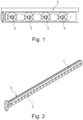
- Figure 1 shows a flip-flop agitator system.
- the agitator (1) is provided within a tubular vessel (2) and is rotated in one direction to accelerate the process fluid radially within the vessel.
- the agitator is then quickly stopped before being driven in the reverse direction, which creates turbulence/mixing.
- Through holes (at least one but not limited in number) (3) are cut into the body of the agitator which permit and encourage radial flow of the process liquid through the agitator body.
- FIG 3 shows a reactor tube (4) in which process fluid flows in the direction shown by the arrows (5) and (6) containing an agitator (7) which can be reciprocated as shown by the arrow (8).
- the reactor is provided with a temperature control jacket (9) through which heat transfer fluid passes as shown by the arrows (10) and (11).
- the heat transfer jacket contains lose spheres (12) and (13) which cause turbulence in the flowing heat transfer fluid.
- Mesh inserts (14) and (15) are provided to hold the spheres within the jacket.
- Figure 4 shows an agitator element (16) with a reactor (17) with a free moving agitator element (18) and a through hole (19), the agitator further containing immobilised particles (such as a catalyst) (20) with the agitator close to the through hole (19).
- immobilised particles such as a catalyst
- the residence time within the reactor for any given process can be described as the amount of time needed to complete the reaction to its best attainable yield using economic and sustainable methods.
- Each different process or unit operation in a reactor will require a different residence. Consequently there is no one size fits all circumstances and the ideal length and diameter of the vessel will vary from process to process.
- the energy released is significant and it is desirable in such circumstances to remove the energy produced as efficiently and as quickly as possible.
- the ratio of heat transfer area to process volume is an important variable and long small diameter tubes are often employed.
- the flow velocity of the process fluid and the energy exchange rate of the heat transfer system are constant along the entire length of the reactor.
- the amount of energy released from the reaction is very different at the start of the reaction to that at the end of the reaction and the lack of control of the process flow velocity/residence time and energy exchange rate can result in a poor yield and a heterogeneous product.
- the outside diameter of the agitator relative to the internal diameter of the tubular vessel may be adjusted, usually reduced, along the length of the reactor.
- the displacement volume of the agitator can be varied along the length of the reactor.
- the relative ratio of heat transfer surface area to process volume is adjusted.
- the change in agitator diameter along the length of the reactor can be either a tapered change or a step change where there is at least 1 step change but no more than 10000, typically no more than 100, step changes in diameter.
- FIG. 5 which shows how a process fluid can flow through a reactor (21) as indicated by arrows (22) and (23).
- the reactor being provided with a heat transfer jacket (24) filled with spheres (25).
- the agitator (26) is split into six sections (27), (28), (29), (30), (31) and (32) of progressively decreasing diameter. In this way the process fluid has a short residence time in section (27) and a progressively increasing residence time as it passes along the reactor giving control of the temperature according to the degree of reaction.
- this technology may be operated in part or as a whole system as a batch or loop reactor.
- a flow crystallization system that filters out undersized particles and reintroduces them to the system either at the start of the reactor or part way along the reactor length.
- the reactors of this invention may be made from a range of materials depending on the nature of the reactants.
- glass e.g. borosilicate and silica quartz
- ceramics e.g. Zirconia and Silicon Carbide
- plastics e.g. PTFE, PFA, PVDF and Peek
- alloy steel e.g. Alloy C276, Tantalum, Titanium and stainless steels
- steel, glass lined (enamelled) steel and plastic lined steel have been found to be particularly useful.
Landscapes
- Chemical & Material Sciences (AREA)
- Chemical Kinetics & Catalysis (AREA)
- Organic Chemistry (AREA)
- Physical Or Chemical Processes And Apparatus (AREA)
Applications Claiming Priority (1)
| Application Number | Priority Date | Filing Date | Title |
|---|---|---|---|
| GB1523157.4A GB2545927A (en) | 2015-12-31 | 2015-12-31 | Improvement in or relating to reactors |
Publications (3)
| Publication Number | Publication Date |
|---|---|
| EP3187258A1 EP3187258A1 (en) | 2017-07-05 |
| EP3187258B1 true EP3187258B1 (en) | 2024-02-07 |
| EP3187258C0 EP3187258C0 (en) | 2024-02-07 |
Family
ID=55406520
Family Applications (1)
| Application Number | Title | Priority Date | Filing Date |
|---|---|---|---|
| EP16207547.7A Active EP3187258B1 (en) | 2015-12-31 | 2016-12-30 | Improvement in or relating to reactors |
Country Status (3)
| Country | Link |
|---|---|
| EP (1) | EP3187258B1 (pl) |
| GB (1) | GB2545927A (pl) |
| PL (1) | PL3187258T3 (pl) |
Families Citing this family (5)
| Publication number | Priority date | Publication date | Assignee | Title |
|---|---|---|---|---|
| CN110117066A (zh) * | 2019-04-28 | 2019-08-13 | 河海大学 | 一种气升式间歇好氧颗粒污泥培养反应器 |
| GB202005191D0 (en) * | 2020-04-08 | 2020-05-20 | Autichem Ltd | Improvement in or relating to tubular reactions |
| CN112934124B (zh) * | 2021-03-19 | 2025-05-02 | 深圳市一正科技有限公司 | 主动混合连续流反应器和反应系统 |
| CN113634216B (zh) * | 2021-08-26 | 2022-05-31 | 大连理工大学 | 一种在管路式反应器中连续重氮化连续偶合生产水溶性偶氮染料的方法 |
| CN118253276B (zh) * | 2024-05-30 | 2024-08-16 | 福建德尔科技股份有限公司 | 一种锂盐原料预反应系统 |
Family Cites Families (7)
| Publication number | Priority date | Publication date | Assignee | Title |
|---|---|---|---|---|
| US2571366A (en) * | 1949-10-04 | 1951-10-16 | Fredrick L Jennings | Portable mixing unit for chemicals and the like |
| FR1307546A (fr) * | 1961-12-05 | 1962-10-26 | Bayer Ag | Réacteur de mélange |
| US4941132A (en) * | 1989-05-04 | 1990-07-10 | Blentech Corporation | Reversing blender agitators |
| DE29805820U1 (de) * | 1998-03-31 | 1998-07-09 | Carl Roth GmbH & Co., 76185 Karlsruhe | Gerät zum Mischen von Flüssigkeiten mit festen Partikeln und zum Aufwirbeln von Sedimenten in Gefäßen |
| JP2002239360A (ja) * | 2001-02-21 | 2002-08-27 | Fuji Carbon Kk | 被処理材撹拌処理装置 |
| CN201216924Y (zh) * | 2008-07-08 | 2009-04-08 | 江苏卡特石油新能源有限公司 | 反应釜的双向搅拌装置 |
| CN202336331U (zh) * | 2011-07-05 | 2012-07-18 | 湖南工业大学 | 高剪切双向搅拌器 |
-
2015
- 2015-12-31 GB GB1523157.4A patent/GB2545927A/en not_active Withdrawn
-
2016
- 2016-12-30 EP EP16207547.7A patent/EP3187258B1/en active Active
- 2016-12-30 PL PL16207547.7T patent/PL3187258T3/pl unknown
Also Published As
| Publication number | Publication date |
|---|---|
| PL3187258T3 (pl) | 2024-07-08 |
| GB201523157D0 (en) | 2016-02-17 |
| EP3187258A1 (en) | 2017-07-05 |
| EP3187258C0 (en) | 2024-02-07 |
| GB2545927A (en) | 2017-07-05 |
Similar Documents
| Publication | Publication Date | Title |
|---|---|---|
| EP3187258A1 (en) | Improvement in or relating to reactors | |
| CN104822446B (zh) | 改进的流动反应器 | |
| KR101084226B1 (ko) | 다중 쿠에트-테일러 와류 반응장치 | |
| KR101901048B1 (ko) | 화학 반응기를 위한 반응 챔버, 및 그로부터 구성된 화학 반응기 | |
| EP2125184B1 (en) | Improved flow reactor | |
| Bittorf et al. | Equipment and separation units for flow chemistry applications and process development | |
| JP7431725B2 (ja) | フローシステムのための改善された混合器 | |
| KR101171333B1 (ko) | 경사원통을 이용하는 와류 반응장치 | |
| KR20110135623A (ko) | 반응효율이 개선되는 와류 반응장치 | |
| CN112934124A (zh) | 主动混合连续流反应器和反应系统 | |
| CN101626824A (zh) | 改进的流动反应器 | |
| EP4132700B1 (en) | Tubular reactor with mixing means | |
| GB2545924A (en) | Improvements in or relating to temperature control systems | |
| McDonough | Process development using oscillatory baffled mesoreactors | |
| WO2014068013A2 (en) | Flow reactor with extended flow path | |
| US20240009636A1 (en) | Improved method and apparatus plug flow system | |
| RU2768926C1 (ru) | Реактор смешения | |
| EP1963373A1 (en) | Horizontal boiling plug flow reactor | |
| Adegun et al. | Numerical Modelling of Mixability of Highly Viscous Syrup in a U-Shaped Tank with Centrally Rotated Streamers | |
| Fadaee | Doctor of Philosophy in Chemical Engineering | |
| Saber et al. | Study of the rate of mass transfer at the wall of the dual impeller agitated vessel | |
| Lechowska et al. | Heat transfer investigations in a liquid that is mixed by means of a reciprocating agitator | |
| Highina et al. | Optimization of Oscillatory and Bulk Flow Reynolds Number in Continuous Oscillatory Baffled Reactor Model for Biodiesel Production |
Legal Events
| Date | Code | Title | Description |
|---|---|---|---|
| PUAI | Public reference made under article 153(3) epc to a published international application that has entered the european phase |
Free format text: ORIGINAL CODE: 0009012 |
|
| STAA | Information on the status of an ep patent application or granted ep patent |
Free format text: STATUS: THE APPLICATION HAS BEEN PUBLISHED |
|
| AK | Designated contracting states |
Kind code of ref document: A1 Designated state(s): AL AT BE BG CH CY CZ DE DK EE ES FI FR GB GR HR HU IE IS IT LI LT LU LV MC MK MT NL NO PL PT RO RS SE SI SK SM TR |
|
| AX | Request for extension of the european patent |
Extension state: BA ME |
|
| STAA | Information on the status of an ep patent application or granted ep patent |
Free format text: STATUS: REQUEST FOR EXAMINATION WAS MADE |
|
| 17P | Request for examination filed |
Effective date: 20180105 |
|
| RBV | Designated contracting states (corrected) |
Designated state(s): AL AT BE BG CH CY CZ DE DK EE ES FI FR GB GR HR HU IE IS IT LI LT LU LV MC MK MT NL NO PL PT RO RS SE SI SK SM TR |
|
| STAA | Information on the status of an ep patent application or granted ep patent |
Free format text: STATUS: EXAMINATION IS IN PROGRESS |
|
| 17Q | First examination report despatched |
Effective date: 20200605 |
|
| P01 | Opt-out of the competence of the unified patent court (upc) registered |
Effective date: 20230524 |
|
| GRAP | Despatch of communication of intention to grant a patent |
Free format text: ORIGINAL CODE: EPIDOSNIGR1 |
|
| RIC1 | Information provided on ipc code assigned before grant |
Ipc: B01F 31/00 20220101ALI20230623BHEP Ipc: B01J 19/18 20060101AFI20230623BHEP |
|
| STAA | Information on the status of an ep patent application or granted ep patent |
Free format text: STATUS: GRANT OF PATENT IS INTENDED |
|
| INTG | Intention to grant announced |
Effective date: 20230803 |
|
| GRAS | Grant fee paid |
Free format text: ORIGINAL CODE: EPIDOSNIGR3 |
|
| GRAA | (expected) grant |
Free format text: ORIGINAL CODE: 0009210 |
|
| STAA | Information on the status of an ep patent application or granted ep patent |
Free format text: STATUS: THE PATENT HAS BEEN GRANTED |
|
| AK | Designated contracting states |
Kind code of ref document: B1 Designated state(s): AL AT BE BG CH CY CZ DE DK EE ES FI FR GB GR HR HU IE IS IT LI LT LU LV MC MK MT NL NO PL PT RO RS SE SI SK SM TR |
|
| REG | Reference to a national code |
Ref country code: GB Ref legal event code: FG4D |
|
| REG | Reference to a national code |
Ref country code: CH Ref legal event code: EP |
|
| REG | Reference to a national code |
Ref country code: DE Ref legal event code: R096 Ref document number: 602016085660 Country of ref document: DE |
|
| REG | Reference to a national code |
Ref country code: IE Ref legal event code: FG4D |
|
| U01 | Request for unitary effect filed |
Effective date: 20240306 |
|
| U07 | Unitary effect registered |
Designated state(s): AT BE BG DE DK EE FI FR IT LT LU LV MT NL PT SE SI Effective date: 20240412 |
|
| P04 | Withdrawal of opt-out of the competence of the unified patent court (upc) registered |
Effective date: 20240412 |
|
| PG25 | Lapsed in a contracting state [announced via postgrant information from national office to epo] |
Ref country code: IS Free format text: LAPSE BECAUSE OF FAILURE TO SUBMIT A TRANSLATION OF THE DESCRIPTION OR TO PAY THE FEE WITHIN THE PRESCRIBED TIME-LIMIT Effective date: 20240607 |
|
| PG25 | Lapsed in a contracting state [announced via postgrant information from national office to epo] |
Ref country code: GR Free format text: LAPSE BECAUSE OF FAILURE TO SUBMIT A TRANSLATION OF THE DESCRIPTION OR TO PAY THE FEE WITHIN THE PRESCRIBED TIME-LIMIT Effective date: 20240508 |
|
| PG25 | Lapsed in a contracting state [announced via postgrant information from national office to epo] |
Ref country code: RS Free format text: LAPSE BECAUSE OF FAILURE TO SUBMIT A TRANSLATION OF THE DESCRIPTION OR TO PAY THE FEE WITHIN THE PRESCRIBED TIME-LIMIT Effective date: 20240507 Ref country code: HR Free format text: LAPSE BECAUSE OF FAILURE TO SUBMIT A TRANSLATION OF THE DESCRIPTION OR TO PAY THE FEE WITHIN THE PRESCRIBED TIME-LIMIT Effective date: 20240207 |
|
| PG25 | Lapsed in a contracting state [announced via postgrant information from national office to epo] |
Ref country code: ES Free format text: LAPSE BECAUSE OF FAILURE TO SUBMIT A TRANSLATION OF THE DESCRIPTION OR TO PAY THE FEE WITHIN THE PRESCRIBED TIME-LIMIT Effective date: 20240207 |
|
| PG25 | Lapsed in a contracting state [announced via postgrant information from national office to epo] |
Ref country code: RS Free format text: LAPSE BECAUSE OF FAILURE TO SUBMIT A TRANSLATION OF THE DESCRIPTION OR TO PAY THE FEE WITHIN THE PRESCRIBED TIME-LIMIT Effective date: 20240507 Ref country code: NO Free format text: LAPSE BECAUSE OF FAILURE TO SUBMIT A TRANSLATION OF THE DESCRIPTION OR TO PAY THE FEE WITHIN THE PRESCRIBED TIME-LIMIT Effective date: 20240507 Ref country code: IS Free format text: LAPSE BECAUSE OF FAILURE TO SUBMIT A TRANSLATION OF THE DESCRIPTION OR TO PAY THE FEE WITHIN THE PRESCRIBED TIME-LIMIT Effective date: 20240607 Ref country code: HR Free format text: LAPSE BECAUSE OF FAILURE TO SUBMIT A TRANSLATION OF THE DESCRIPTION OR TO PAY THE FEE WITHIN THE PRESCRIBED TIME-LIMIT Effective date: 20240207 Ref country code: GR Free format text: LAPSE BECAUSE OF FAILURE TO SUBMIT A TRANSLATION OF THE DESCRIPTION OR TO PAY THE FEE WITHIN THE PRESCRIBED TIME-LIMIT Effective date: 20240508 Ref country code: ES Free format text: LAPSE BECAUSE OF FAILURE TO SUBMIT A TRANSLATION OF THE DESCRIPTION OR TO PAY THE FEE WITHIN THE PRESCRIBED TIME-LIMIT Effective date: 20240207 |
|
| PG25 | Lapsed in a contracting state [announced via postgrant information from national office to epo] |
Ref country code: SM Free format text: LAPSE BECAUSE OF FAILURE TO SUBMIT A TRANSLATION OF THE DESCRIPTION OR TO PAY THE FEE WITHIN THE PRESCRIBED TIME-LIMIT Effective date: 20240207 |
|
| PG25 | Lapsed in a contracting state [announced via postgrant information from national office to epo] |
Ref country code: CZ Free format text: LAPSE BECAUSE OF FAILURE TO SUBMIT A TRANSLATION OF THE DESCRIPTION OR TO PAY THE FEE WITHIN THE PRESCRIBED TIME-LIMIT Effective date: 20240207 |
|
| PG25 | Lapsed in a contracting state [announced via postgrant information from national office to epo] |
Ref country code: SK Free format text: LAPSE BECAUSE OF FAILURE TO SUBMIT A TRANSLATION OF THE DESCRIPTION OR TO PAY THE FEE WITHIN THE PRESCRIBED TIME-LIMIT Effective date: 20240207 |
|
| PG25 | Lapsed in a contracting state [announced via postgrant information from national office to epo] |
Ref country code: SM Free format text: LAPSE BECAUSE OF FAILURE TO SUBMIT A TRANSLATION OF THE DESCRIPTION OR TO PAY THE FEE WITHIN THE PRESCRIBED TIME-LIMIT Effective date: 20240207 Ref country code: SK Free format text: LAPSE BECAUSE OF FAILURE TO SUBMIT A TRANSLATION OF THE DESCRIPTION OR TO PAY THE FEE WITHIN THE PRESCRIBED TIME-LIMIT Effective date: 20240207 Ref country code: RO Free format text: LAPSE BECAUSE OF FAILURE TO SUBMIT A TRANSLATION OF THE DESCRIPTION OR TO PAY THE FEE WITHIN THE PRESCRIBED TIME-LIMIT Effective date: 20240207 Ref country code: CZ Free format text: LAPSE BECAUSE OF FAILURE TO SUBMIT A TRANSLATION OF THE DESCRIPTION OR TO PAY THE FEE WITHIN THE PRESCRIBED TIME-LIMIT Effective date: 20240207 |
|
| REG | Reference to a national code |
Ref country code: DE Ref legal event code: R097 Ref document number: 602016085660 Country of ref document: DE |
|
| PLBE | No opposition filed within time limit |
Free format text: ORIGINAL CODE: 0009261 |
|
| STAA | Information on the status of an ep patent application or granted ep patent |
Free format text: STATUS: NO OPPOSITION FILED WITHIN TIME LIMIT |
|
| 26N | No opposition filed |
Effective date: 20241108 |
|
| U20 | Renewal fee for the european patent with unitary effect paid |
Year of fee payment: 9 Effective date: 20241212 |
|
| PG25 | Lapsed in a contracting state [announced via postgrant information from national office to epo] |
Ref country code: MC Free format text: LAPSE BECAUSE OF FAILURE TO SUBMIT A TRANSLATION OF THE DESCRIPTION OR TO PAY THE FEE WITHIN THE PRESCRIBED TIME-LIMIT Effective date: 20240207 |
|
| GBPC | Gb: european patent ceased through non-payment of renewal fee |
Effective date: 20241230 |
|
| PG25 | Lapsed in a contracting state [announced via postgrant information from national office to epo] |
Ref country code: GB Free format text: LAPSE BECAUSE OF NON-PAYMENT OF DUE FEES Effective date: 20241230 |
|
| PG25 | Lapsed in a contracting state [announced via postgrant information from national office to epo] |
Ref country code: IE Free format text: LAPSE BECAUSE OF NON-PAYMENT OF DUE FEES Effective date: 20241230 |
|
| REG | Reference to a national code |
Ref country code: CH Ref legal event code: U11 Free format text: ST27 STATUS EVENT CODE: U-0-0-U10-U11 (AS PROVIDED BY THE NATIONAL OFFICE) Effective date: 20260101 |
|
| PGFP | Annual fee paid to national office [announced via postgrant information from national office to epo] |
Ref country code: PL Payment date: 20251222 Year of fee payment: 10 |
|
| U20 | Renewal fee for the european patent with unitary effect paid |
Year of fee payment: 10 Effective date: 20251230 |
|
| PGFP | Annual fee paid to national office [announced via postgrant information from national office to epo] |
Ref country code: CH Payment date: 20260101 Year of fee payment: 10 |
|
| PG25 | Lapsed in a contracting state [announced via postgrant information from national office to epo] |
Ref country code: CY Free format text: LAPSE BECAUSE OF FAILURE TO SUBMIT A TRANSLATION OF THE DESCRIPTION OR TO PAY THE FEE WITHIN THE PRESCRIBED TIME-LIMIT Effective date: 20240207 |